1
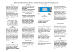
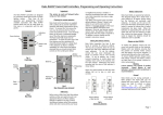
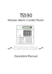
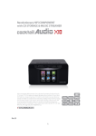
RTC-Bridge User Manual Contents RTC-Bridge User Manual............................................................................................................................... 1 What is RTC-Bridge ................................................................................................................................... 2 Getting started with RTC-Bridge............................................................................................................... 2 Basic Configuration of the RTC-Bridge ..................................................................................................... 3 Setting House Number and Geographic Location ................................................................................ 3 Using RTC-Bridge with Rasoft Software ................................................................................................... 4 RTC-Bridge Events..................................................................................................................................... 5 Using the Web Interface with RTC-Bridge Events ................................................................................ 5 Using Rasoft with RTC-Bridge Events ................................................................................................... 6 RTC-Bridge Mapping ................................................................................................................................. 7 Triggering Macros from Maps .............................................................................................................. 8 RTC-Bridge Macros ................................................................................................................................... 9 An example Macro.............................................................................................................................. 10 Interfacing Smart Phones to Rako System using RTC-Bridge ................................................................. 11 Equipment List: ................................................................................................................................... 11 Step 1: Connect the Bridge to the router. .................................................................................. 11 Step 2: Set the Bridge to the same House ID number as your Rako system. ............................. 11 Step 3: Upload Room and Scene information to the Bridge. ..................................................... 11 Step 4: Use RAKO Smart Phone application to control the lighting system. .............................. 12 Holiday Mode ......................................................................................................................................... 13 Holiday Mode Recording .................................................................................................................... 13 Holiday Mode Playback ...................................................................................................................... 13 Monitor Mode ........................................................................................................................................ 14 Sonos Control ......................................................................................................................................... 14 RTC-Bridge Firmware Upgrades ............................................................................................................. 15 Appendix 1: How to discover House and room numbers by looking at wall plates ............................... 16 Appendix 2: Configuring a Rasoft file to work with Smart Phone .......................................................... 17 Issue 1 October 2011 Page 1 of 19 What is RTC-Bridge RTC-Bridge will add the following features to a RAKO wireless system: Ethernet interface, including remote control via Smart Phone. Timed Events. Automatic functions at fixed times or triggered by dawn & dusk times. Mapping. Commands from wall controllers can be redirected to perform other tasks. Macros. Complex series of commands that are triggered by a single command or event. Holiday Mode. Replays recorded scene activity, creating an occupied look to a property. Monitor. Diagnostic display of system activity. Getting started with RTC-Bridge Some initial setup of RTC-Bridge is needed. First, Plug the RTC Power Supply into the RTC-Bridge and apply power. The RTC-Bridge display will light up and there will be a short beep. Plug the Ethernet patch cable from the RTC-Bridge to a spare port on a wireless router. Use a normal web browser (eg Internet Explorer) to connect to the RTC-Bridge via the router. The default RTC-Bridge URL is http://rakobridge Or Use a laptop to connect to the RTC-Bridge http://rakobridge.local Use a Web Browser to view the RTC Bridge control panel. Issue 1 October 2011 Page 2 of 19 Basic Configuration of the RTC-Bridge Setting House Number and Geographic Location Click the Configuration button on the RTC-Bridge control panel. Login User Name = admin Password = microchip The Rako Bridge Configuration screen allows several settings to be changed. The most important are highlighted below. Change WTC-Bridge House address (The House Address must match the rest of the Rako Wireless system) Set location Correct location and time zone must be entered so that Bridge can calculate times for Dawn and Dusk. In South East England the default settings UTC 0, Latitude 51 and Longitude 0 are correct Save Config Issue 1 October 2011 Page 3 of 19 Setting the Time and Date The RTC-Bridge Display shows current Date and Time Information. This can be set manually by pressing the buttons on the front of the RTC-Bridge. Normally RTC-Bridge will be connected by RJ45 lead to a router. If this router is connected to Internet then the time will normally automatically update. RTC-Bridge also has battery backed up Real Time Clock to prevent loss of time setting due to loss of power etc. Using RTC-Bridge with Rasoft Software Use Rasoft Software with RTC-Bridge to program a Rako Wireless system and the RTC-Bridge itself. On the laptop, Run Rako Lighting RASOFT program. After a short delay the Rasoft start up screen will be displayed. If a Timeout error occurs then click OK. The Rasoft start up screen will appear shortly. Go to the Rasoft Controls - Communication screen. The Communication Check boxes should be set like this for RASOFT to find Bridge easily. Then Quit and Restart Rasoft so that an error free startup of Rasoft occurs. 192.168.1.100 If Rasoft is communicating with the RTC-Bridge Correctly then it will display an IP address below the IP/NetBios Name. Rasoft start up screen Tip: It can take a minute or two from connecting the bridge to the router & switching it on, before RASOFT is able to talk to it . Issue 1 October 2011 Tip: Do not have any Rako USB or RS232 devices connected to your computer as these will interfere with the Bridge setup process Page 4 of 19 RTC-Bridge Events The RTC-Bridge can generate automated Events that occur at specific times. As an example; the RTC-Bridge can be programmed to make garden lighting be switched On at Dusk and Off at midnight each day. Events can be viewed, added and changed by using the RTC-Bridge Web Interface, or by using the RASOFT program. Using the Web Interface with RTC-Bridge Events Access the RTC-Bridge Events Screen from the Configuration screen This example shows an Event which sets Scene 1 in Room 4 at 9:20 AM on weekdays. List of Events stored in the RTC-Bridge. Events 1,2,3 are active. The screen is currently displaying Event 1 Store the Event in RTCBridge by pressing Update Event Test the Event by pressing Trigger Event Issue 1 October 2011 Page 5 of 19 Using Rasoft with RTC-Bridge Events RTC-Bridge Events can also be viewed and edited using RASOFT software. The RTC-Bridge Events Screen is located under Controls-Bridge-Events This Bridge Events screen is displaying the same Example Event as previously which sets Scene 1 in Room 4 at 9.20AM on weekdays. To add or edit an Event, simply highlight it from the list at the bottom part of the window. Make sure the Event Trigger is Enabled. Set up the Event as required then press the Save button. The Upload button must be used to write Events from Rasoft to the RTC-Bridge. This will overwrite any events that are already in the RTC-Bridge. The Download button is used to read Events already stored in the RTC-Bridge back into Rasoft. This will overwrite any events that are already in Rasoft. The Verify button can be used to check that the Events in Rasoft and those in the RTC-Bridge match with each other. Issue 1 October 2011 Page 6 of 19 RTC-Bridge Mapping RTC-Bridge Mapping screen is located at Controls-Bridge-Mapping When Mapping is used the RTC-Bridge will listen to the Rako Commands sent by Wall Controllers, Smart Phones, Hand Held remotes etc . When the RTC-Bridge hears a command that matches one of its Maps it will perform a specified Action. In the example above the RTC-Bridge has two Maps programmed. Map 1 is being displayed. When a Room 6, Scene 1 Command is received the RTC-Bridge will transmit a Room 11, Scene 1 command. This particular Map is active on all days of the week, but only operates at Night. The fade rate slider and check box are only used in Rako Wired systems, so are not relevant to RTCBridge. The Upload button must be used to write Mappings from Rasoft to the RTC-Bridge. This will overwrite any Mappings that are already in the RTC-Bridge. The Download button is used to read Mappings already stored in the RTC-Bridge back into Rasoft. This will overwrite any Mappings that are already in Rasoft. The Verify button can be used to check that the Mappings in Rasoft and those in the RTC-Bridge match with each other. Maps do not have to simply translate one Scenes simply into another scene. Maps can trigger a variety of Actions as shown here Issue 1 October 2011 Page 7 of 19 Map 2 in this example shows how a scene command (Room 99, Scene 1) can start a Macro. This Map is active at any time on any day of the week. (The Room Number 1000 refers to the RTC-Bridge Room number as set in the Rako Bridge Configuration web page) Triggering Macros from Maps A Map can trigger a Macro in several ways: Start will cause the Macro to start from the beginning. Stop will cause a Macro that is already running to cease (and return to the beginning). Pause will cause a Macro to Pause at whatever step it is currently running. Continue will cause the Macro to continue from a Paused state, performing the next step. Issue 1 October 2011 Page 8 of 19 RTC-Bridge Macros Macros allow a sequence of actions to take place when triggered by an Event or Map The RTC-Bridge Macro screen is located at Controls-Bridge-Macros RTC-Bridge can store up to 64 Macros. This example shows Macro 1. There are 3 steps to the Macro, each of which is a simple Scene Command. Each Macro step can be one of 3 types Instruction: Can be one of the types shown to the right Pause/Delay: The Macro can pause for a time delay, or can pause until it is retriggered by a Map Goto: The Macro can jump to another step in the Macro (usually back to the beginning), or can jump to a different Macro. Issue 1 October 2011 Page 9 of 19 An example Macro Macro that performs a toggle function Consider this Macro. When it is started it will transmit a Room 1 Scene 1 command. It will then Pause at Step 2 and remain there until the Macro is retriggered. If the Macro is triggered to continue, it will move to step 3 All the step after step 3 are disabled. Scrolling down to the end of the Macro reveals that all Macros have an implicit Pause and Goto Step 1 at their ends. So, after running step 3 the Macro will pause at the end. If Macro is then triggered again to continue it will go back to step 1. Thus this Macro performs a toggle function between Scene 1 and Off – Each time it receives a continue it will toggle the scene on or off. HOWEVER – There is a problem with this Macro! When a Wallplate transmits a scene command it repeats the message 3 times to increase the wireless system reliability. With this type of Macro the macro will trigger on reception of the first wallplate transmission. The Macro will finish before the last wallplate transmission is received. This causes a second triggering of the Macro. The result is that that the toggle does not work. The correct form for this Macro is: Delays have added to slow the Macro down. Even though these delays have zero value they make enough difference to prevent the Macro running too quickly. Issue 1 October 2011 Page 10 of 19 Interfacing Smart Phones to Rako System using RTC-Bridge Equipment List: A RAKO lighting system. An RTC-Bridge. A Smart Phone (Android or Iphone), IPad or IPod Touch A Wireless network (with spare router Ethernet connector). A PC with the supplied RASOFT software installed (version 2.2.7 or later). The RASOFT Configuration file for the house. (The person who commissioned the lighting system should be able to provide this) If this is not available, then see appendix 1 to create one. Phone talks to RTC-Bridge through router Wireless router RTC-Bridge connects to Router by Ethernet cable Laptop configures RTC-Bridge by talking to it through wireless router ac power adapter for Bridge RTC-Bridge RTC-Bridge talks to Rako system using wireless radio link Step 1: Connect the Bridge to the router. See the previous section “Getting Started with RTC-Bridge”. Step 2: Set the Bridge to the same House ID number as your Rako system. Every RAKO wireless system has a House ID number between 1 and 255. It is necessary to tell the Bridge what house ID number has been set so that it talks to the correct house (and not the neighbours!).If the House number is unknown look at the DIP switches settings on the rear of the lighting control wall plates and decode the house ID number from those. Use Web Browser to set correct House number as shown in previous section “Setting House Number & Geographic location” Appendix 1 shows how to decode the wall plate switch settings. Step 3: Upload Room and Scene information to the Bridge. The Bridge needs to be told about how the RAKO system has been configured. This is done by using the RASOFT program (version 2.2.7 or later) combined with the RASOFT Configuration file that was used to set the system up. Issue 1 October 2011 Page 11 of 19 Open the configuration file for the house’s RAKO system: If the RASOFT configuration is not available, then refer to appendix 2 to create one. When the Configuration File is successfully loaded: Open the Bridge Setup menu item. and a number of Rooms, channels etc appear. Click on Get Room Data…. Now just click on Upload to transfer the Room data to the Bridge. Should take a few moments to complete. TIP: For best results tick either the “Only Enabled Channels” or “Ignore Blank Channels” check box. Step 4: Use RAKO Smart Phone application to control the lightingThese boxes are ticked by default in later versions of Rasoft system. Make sure the Phone is able to connect to the router. Download the RAKO application from the app store. Run the application. The phone will find the RTC-Bridge after a few moments. The Rako application will display the room and scene information that has been uploaded to the bridge. Issue 1 October 2011 Page 12 of 19 Holiday Mode Holiday mode allows the RTC-Bridge to record normal lighting activity in a property over a period. This can then be replayed whilst the property is empty in order to give a realistic impression that it is occupied. Holiday Mode Recording The RTC-Bridge must record activity for a period of at least 24 hours before the Holiday Mode can be used. Use the buttons on the front of the RTC-Bridge. To start Record: Press the circle button until Holiday is displayed. Press the Tick button until Holiday – Start Record is displayed. Press the Tick button so that Holiday Record is displayed. After a few seconds the display will revert to showing the current date and time. A Flashing “R” symbol at the right hand side of the display indicates that the unit is in Holiday Record mode Holiday Mode Playback The RTC-Bridge must record activity for at least 24 hours before Playback can be enabled. Use the buttons on the front of the RTC-Bridge To start Playback: Press the Circle button until Holiday Idle is displayed Press the Tick button until Holiday Idle – Replay is displayed Press the Tick button so that Holiday Replay is displayed After a few seconds the display will revert to showing the current date and time. A Flashing “H” symbol at the right hand side of the display indicates that the unit is in Holiday Replay mode Issue 1 October 2011 Page 13 of 19 Monitor Mode In Monitor Mode the RTC-Bridge display will show the last Rako Command that has been received. This is a very useful diagnostic tool. The monitor display can display the commands in two ways: Either as Decoded Instructions, or as Raw Data. Most users will be interested in Decoded Instructions. To enable Monitor Mode: Press the Circle button until Monitor is displayed. Press the Tick button so that either Monitor-Raw or Monitor-decode is displayed The RTC-Bridge will now display any commands received. Note – only Commands for the same House Number as set in the RTC-Bridge are shown. Commands from other House Numbers are ignored. Decoded display Room 65 Channel 0 Scene 2 Source = Wireless Wallplate Decoded display Room 6 Channel 0 Scene 1 Source = Smart Phone Sonos Control RTC-Bridge can be used to enable control of a Sonos Wireless HiFi Audio System from the Rako. This requires upgrade of RTC-Bridge using additional ACM plug in module. Issue 1 October 2011 Page 14 of 19 RTC-Bridge Firmware Upgrades Periodically RTC-Firmware updates are posted on Rako Website. The Rasoft software will scan for these updates automatically when it has web access. To check for Firmware Update in Rasoft go to Controls-Wired-Bridge-Setup Bridge Setup screen shows the Current version of Bridge firmware and latest version available. To Upgrade the firmware press the Firmware button. Text box shows new Firmware file to send to bridge Button for manual selection of Firmware Upgrade file – refer to Rako Tech support Button to start the Upgrade process The Upgrade will take 4 to 5 minutes during which the progress bar will run through twice. Do not tamper with the Rako system whilst the upgrade is occuring Issue 1 October 2011 Page 15 of 19 Appendix 1: How to discover House and room numbers by looking at wall plates Look at Control Panel (Wall Plate) to discover House and Room settings Here Unscrew and remove Front from Wall plate Note: Other versions and models of room controllers also exist. Construction of these is different, but the way in which House and Room setting are done is the same. Inspect ‘House’ and ‘Room’ settings Prise rear cover from wall plate by pulling at position marked above Rasoft can be used to decode the settings into House number and Room numbers. In Rasoft go to ‘Help’, then ‘Switch Settings’ Move the On-Screen switches to match those of the wall plate to see the House and Room numbers. In the example above, the House address is 105 and the Room number is 50 (Normally, all room controllers will have same House Address, and differing Room Addresses – The ARP Bridge requires all controllers to have same House Address) Issue 1 October 2011 Page 16 of 19 Appendix 2: Configuring a Rasoft file to work with Smart Phone Discover House and Room Numbers It is first necessary to find out the House and Room addresses of each control panel. To do this each one needs to be removed from the wall and it’s address switches examined. The address numbering is binary coded, this can be translated into decimal using Rasoft . See appendix 2 for more detail. Make notes of the Room Number and Location of each Control Panel. A list like this will contain the information that you need: Location Room Number Dining room 6 Kitchen 8 Outside Lights 13 Master Bedroom 11 Bedroom 2 12 Etc etc ….. Some rooms may contain multiple control plates with same settings as each other. This is normal. You only need to record one of them. Enter Room Numbers into Rasoft When there is a complete list of Room Controllers the information can be entered into a RASOFT File. If the House address has not yet been programmed into the APR Bridge, then do so now. Follow steps 1 & 2 on Pages 2 & 3 of this document. Run the Rako Lighting program on a PC or Laptop. Rasoft start up screen House number is greyed out when using Rasoft with RTC-Bridge From the start up screen select ‘Save’ from the File menu then choose ‘Save and edit’. This creates a new project file, leaving the original blank for use later if further projects are planned. Any changes made to the project file are saved live and do not need to be saved at the end of programming. Select ‘Channel Controls’ to begin entering the room numbers. Issue 1 October 2011 Page 17 of 19 Use the ‘Add’ button in the bottom right hand corner of the Channel Control window to create rooms. Number them according to the address switches of the panels within the rooms. ‘Add’ button Type in the Room Names and Room Numbers from the list made earlier. When the rooms have been added they will show as a list in the bottom right hand corner of the Channel Control window. Give Scenes Names Delete the Default Room 4. Or rename it if it being used For each room the scenes 1 to 4 can be given a descriptive name. Issue 1 October 2011 Page 18 of 19 Enter Channel Names into Rasoft As well as allowing selection of Rooms and Scenes, the iphone Application can control individual circuits within the house. To do this properly the channels in each room must be identified. At the Left hand side of the Channel control window, press the Channel 1 Ident Button and observe which lights flash on & off in the room. Type a description of these lights in the Channel 1 description. Tick the Enable box for that channel. Repeat for each channel in all rooms until all lights have been identified. Any channels that are not being used (i.e. no lights flash when the Ident button is pressed) should be left with a blank description and the enable box should be un-ticked. Channel 1 Enabled Channel 1 Ident Button Channel 1 description Unused channel disabled Unused channel description left blank Select which rooms and circuits should appear in the iphone application The Rabridge Setup utility has two check boxes. These are used to prevent the iphone application being clogged up with unwanted menu items which refer to unused channels. The Bridge can only hold information for 256 channels: Unused channels will quickly exceed this limit if neither of these boxes are ticked. By ticking ‘Only Enabled Channels’ the iphone will only use channels that are ticked as enabled within the Rasoft Channel control window. By ticking ‘Ignore Blank Channels’ the iphone will only use channels that have been given proper descriptive names. In addition, an entire room can be omited from the iphone. To do this, simply tick the “Not on Smart Remote” box at the top of the Channel control screen. ____________________________________________________________________________________ Technical Support For more information contact Rako Controls Ltd 01634 226666 www.rakocontrols.com Issue 1 October 2011 Page 19 of 19