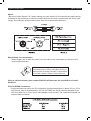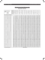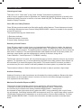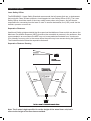
1
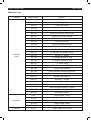
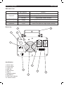
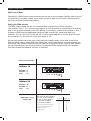
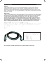
VIRGO
order code: EQLA04
user manual
Equinox Virgo Laser
Safety
WARNING
FOR YOUR OWN SAFETY, PLEASE READ THIS USER MANUAL CAREFULLY
BEFORE YOUR INITIAL START-UP!
CAUTION!
Keep this equipment away from rain,
moisture and liquids.
SAFETY INSTRUCTIONS
Every person involved with the installation, operation & maintenance of this
equipment should:
-
Be competent
-
Follow the instructions of this manual
CAUTION! TAKE CARE USING THIS EQUIPMENT!
HIGH VOLTAGE-RISK OF ELECTRIC SHOCK!!
Before your initial start-up, please make sure that there is no damage caused during
transportation. Should there be any, consult your dealer and do not use the
equipment.
To maintain the equipment in good working condition and to ensure safe operation, it is necessary
for the user to follow the safety instructions and warning notes written in this manual.
Please note that damages caused by user modifications to this equipment are not
subject to warranty.
Equinox Virgo Laser
Safety
IMPORTANT:
The manufacturer will not accept liability for any resulting damages caused
by the non-observance of this manual or any unauthorised modification to the
equipment.
• Never let the power-cable come into contact with other cables. Handle the power-cable
and all mains voltage connections with particular caution!
• Never remove warning or informative labels from the equipment.
• Do not open the equipment and do not modify the equipment.
• Do not connect this equipment to a dimmer-pack.
• Do not switch the equipment on and off in short intervals, as this will reduce the
system’s life.
• Only use the equipment indoors.
• Do not expose to flammable sources, liquids or gases.
• Always disconnect the power from the mains when equipment is not in use or before
cleaning! Only handle the power-cable by the plug. Never pull out the plug by pulling the
power-cable.
• Make sure that the available voltage is between 220v/240v.
• Make sure that the power-cable is never crimped or damaged. Check the equipment and
the power-cable periodically.
• If the equipment is dropped or damaged, disconnect the mains power supply immediately.
Have a qualified engineer inspect the equipment before operating again.
• If the equipment has been exposed to drastic temperature fluctuation (e.g. after
transportation), do not switch it on immediately. The arising condensation might damage
the equipment. Leave the equipment switched off until it has reached room temperature.
• If your product fails to function correctly, discontinue use immediately. Pack the unit
securely (preferably in the original packing material), and return it to your Prolight dealer
for service.
• Only use fuses of same type and rating.
• Repairs, servicing and power connection must only be carried out by a qualified
technician. THIS UNIT CONTAINS NO USER SERVICEABLE PARTS.
• WARRANTY; One year from date of purchase.
OPERATING DETERMINATIONS
If this equipment is operated in any other way, than those described in this manual,
the product may suffer damage and the warranty becomes void.
Incorrect operation may lead to danger e.g.: short-circuit, burns, electric shocks,
lamp failure etc.
Do not endanger your own safety and the safety of others!
Incorrect installation or use can cause serious damage to people and property.
Equinox Virgo Laser
Technical specification
You should find inside the Laser carton the following items:
1, Virgo Laser
2, Power cable
3, DMX cable
4, Instruction manual
Technical Specifications:
Voltage: 240V AC 50Hz
Laser diode: 1 x 40mW Green (532nm) DPSS laser
1 x 80mW Red (650nm) DPSS laser
Operating modes: 1, Stand Alone Sound Activated
2, Stand Alone Auto programme
3, DMX-512 8 channels
Features:
Over 100 laser patterns, with adjustable scan rate, position and size giving a total of over 300
effects.
Function Settings:
1, Stand Alone Sound Activated, set all dip switches to off. Then use the
sensitivity control to set the desired activation level.
2, Stand Alone Auto Programme change, set dip switch 10 to on and all others to off.
3, For DMX operation set dip switch 10 to off, then set the desired address using dip
switches 1 - 9
When used in DMX mode please note:
Set Channel 1 to DMX No: 0 to 50 for sound active mode.
Set Channel 1 to DMX No: 51 to 101 then using Channel 2 you can scroll through the 58 patterns
as listed below.
Set Channel 1 to DMX No: 102 to 152 then using Channel 3 you can obtain the single shapes
listed. With the single shapes selected you can then use
- Channel 4 to zoom
- Channel 5 for rotation
- Channel 6 for X movement
- Channel 7 for Y movement
- Channel 8 for scan speed
Set Channel 1 to DMX No: 153 to 203, the laser will then go into Auto run mode
Set Channel 1 to DMX No: 204 to 255, the laser will then go into Blackout mode.
Note: The maximum number of units that can be linked in Master/Slave mode is 32. The patterns
are not perfect (squares, circles, triangles etc) as the unit uses stepper motors and not Galvo’s but
are ideal for use with smoke machines and to make lines and tunnels etc.
When using long DMX runs or multiple heads. A DMX terminator plug should be used on the last
head in the chain.
Equinox Virgo Laser
DMX Tables
DMX table:
Channel
Channel 1
Channel 2
(Pattern mode 1)
DMX Number
Function
0-50
Sound Activated mode
51-101
Pattern mode 1
102-152
Pattern mode 2
153-203
Auto running
204-255
Blackout
0-03
Circle zoom in/out
04-07
Short line rotation
08-11
Circle rotates around “X” axis
12-15
Circle rotates around “Y” axis
16-19
Circle
20-23
Circle rotates around “Y” axis
24-27
Circle moves left and right
28-31
Half circle
32-35
Half circle rotates around X” axis
36-39
Half circle rotates around “Y” axis
40-43
Half circle moves right and left
44-47
“W” rotation around “X” axis
48-51
52-55
“W” rotation around “Y” axis
Wave rotation around “X” axis
56-59
Line flows like a wave
60-63
Wave move left and right
64-67
Square zoom in
68-71
Square moves around “X” axis
72-75
Square moves around “Y” axis
76-79
Square zoom out and rotation
80-83
Triangle zoom in/out
84-87
Triangle zoom out and rotation
88-91
Moving triangle
92-95
Moving line
96-99
Moving pentangle
100-103
Pentangle moves right and left
104-107
Line moves up and down
108-111
Line rotation
112-115
116-119
Line rotates around “Y” axis
Vertical line moves right to left
Equinox Virgo Laser
DMX Tables
DMX table Cont:
Channel
Channel 2
(cont)
Channel 3
Channel 4
DMX Number
Function
120-123
vertical line rotates around “X” axis
124-127
Rotating leaf
128-131
Leaf zoom in/out
132-135
Hexagon zoom in/out
136-139
Hexagon Rotation
140-143
Small circle moves left and right
144-147
Small circle moves around
148-151
Small circle moves around
152-155
Dot move around
156-159
Short line flows like wave
160-163
Cloud moves left and right
164-167
Cloud rotation around Y axis
168-171
Cloud zoom out around X axis
172-175
Moving “V” shape
176-179
“V” rotation around “X” axis
180-183
“V” rotation around “Y” axis
184-187
“V” zoom in/out
188-191
192-195
“V” rotation around “Z” axis
Single wave rotation
196-199
Short line flows around single wave
200-203
Short line flows around double wave
204-207
Double wave zoom in
208-211
Rotating “+” shape
212-215
Zooming “+” sign
216-219
Line rotation around centre
220-223
Short line flows around “8” shape
224-227
“8” rotation
228-255
Rectangle rotation
0-50
Single shape 1 (line)
51-101
Single shape 2 (circle)
102-152
Single shape 3 (square)
153-203
Single shape 4 (dot)
204-255
Single shape 5 (triangle)
0-255
Single shape zoom in/out
Equinox Virgo Laser
DMX Tables
DMX table Cont:
Channel
DMX Number
Function
0-49
Single shape stops rotation
50-149
Single shape rotate anti-clockwise
150-255
Single shape rotate clockwise
Channel 6
0-255
Single shape moves around X axis
Channel 7
0-255
Single shape moves around Y axis
Channel 8
0-255
Controls the speed of single shape scanning
Channel 5
Back view:
10
7
8
9
1
Identification:
1, Power input
2, Power switch
3, Cooling fan
4, DMX out
5, Dip switches
6, DMX in
7, Hanging bracket
8, Microphone
9, LED power indicator
10, Volume control
4
2
5
3
6
Equinox Virgo Laser
DMX control mode
DMX Control Mode
Operating in a DMX control mode environment gives the user the greatest flexibility when it comes
to customising or creating a show. In this mode you will be able to control each individual trait of
the fixture and each fixture independently.
Setting the DMX address
The DMX mode enables the use of a universal DMX controller. Each fixture requires a
“start address” from 1- 511. A fixture requiring one or more channels for control begins to read the
data on the channel indicated by the start address. For example, a fixture that occupies or uses 7
channels of DMX and was addressed to start on DMX channel 100, would read data from
channels: 100,101,102,103,104,105 and 106. Choose a start address so that the channels used
do not overlap. E.g. the next unit in the chain starts at 107.
Set the start address using the group of dip switches located usually on the back of the fixture.
Each dip switch has an associated value. Adding the value of each switch in the ON position will
provide the start address. Determining which switches to toggle ON given a specific start address
can be accomplished in the following manner. By subtracting the largest switch value possible
from the selected start address until zero is achieved.
EXAMPLE STARTING ADDRESS
Address 10
on
Pin NO: 4 = 8
Pin NO: 2 = 2
Total
= 10
Address 24
on
Pin NO: 5 = 16
Pin NO: 4 = 8
Total
= 24
DMX address using
simple maths
233 - (128 = 105, Turn on dip No: 8
105 - (64) = 41, Turn on dip No:7
41 - (32) = 9, Turn on dip No: 6
9 - (8) = 1, Turn on dip No: 4
1 - (1) = 0, Turn on dip No:1
You will most likely use the first available
number which maybe Number 1. This
number was selected for
example purposes
DIP SWITCH
1
2
3
4
5
6
7
8
9
10
(DMX VALUE)
1
2
4
8
16
32
64
128
256
Equinox Virgo Laser
DMX Set up
DMX-512:
• DMX (Digital Multiplex) is a universal protocol used as a form of communication between
intelligent fixtures and controllers. A DMX controller sends DMX data instructions form the
controller to the fixture. DMX data is sent as serial data that travels from fixture to fixture via the
DATA “IN” and DATA “OUT” XLR terminals located on all DMX fixtures (most controllers only have
a data “out” terminal).
DMX Linking:
• DMX is a language allowing all makes and models of different manufactures to be linked together
and operate from a single controller, as long as all fixtures and the controller are DMX compliant.
To ensure proper DMX data transmission, when using several DMX fixtures try to use the
shortest cable path possible. The order in which fixtures are connected in a DMX line does not
influence the DMX addressing. For example; a fixture assigned to a DMX address of 1 may be
placed anywhere in a DMX line, at the beginning, at the end, or anywhere in the middle. When a
fixture is assigned a DMX address of 1, the DMX controller knows to send DATA assigned to
address 1 to that unit, no matter where it is located in the DMX chain.
DATA Cable (DMX cable) requirements (for DMX operation):
• The Equinox laser can be controlled via DMX-512 protocol. The DMX address is set on the back
of the unit. Your unit and your DMX controller require a standard 3-pin XLR connector for data
input/output (figure 1).
Figure 1
Further DMX cables can be purchased
from all good sound and lighting suppliers
or Prolight dealers.
Please quote:
CABL10 – 2M
CABL11 – 5M
CABL12 – 10M
Also remember that DMX cable must be daisy chained and cannot be split.
Equinox Virgo Laser
DMX Set Up
Notice:
• Be sure to follow figures 2 & 3 when making your own cables. Do not connect the cable’s shield
conductor to the ground lug or allow the shield conductor to come in contact with the XLR’s outer
casing. Grounding the shield could cause a short circuit and erratic behaviour.
Special Note: Line termination:
• When longer runs of cable are used, you may need to use a terminator on the last unit to
avoid erratic behaviour.
Termination reduces signal transmission problems
and interferance. it is always advisable to connect a
DMX terminal, (resistance 120 Ohm 1/4 W) between
pin 2 (DMX-) and pin 3 (DMX+) of the last fixture.
Using a cable terminator (part number CABL90) will decrease the possibilities of erratic
behaviour.
5-Pin XLR DMX Connectors:
• Some manufactures use 5-pin XLR connectors for data transmission in place of 3-pin. 5-Pin
XLR fixtures may be implemented in a 3-pin XLR DMX line. When inserting standard 5-pin
XLR connectors in to a 3-pin line a cable adaptor must be used. The Chart below details the
correct cable conversion.
Equinox Virgo Laser
DMX Dip Switch Quick Reference Chart
Dip Switch Position
Dip Switch position
DMX Address
Dip Switch Reference Chart
Equinox Virgo Laser
Safety
Class 3B Laser Safety Guide
Warning
Class 3B Lasers have the potential to harm eyesight if viewed directly and can also be
harmful at long distances.
Any unit that contains a laser diode has to be classified depending upon the light output that
someone may be exposed to. All laser products are classed as defined in the
Laser Product Safety Standard (BS/EN 60825.1). The classes range from the safest, which is
Class 1, through to the most hazardous, which is Class 4. A laser diode that emits more than 5mW
of light and less than 500mW can be classified as a Class 3B product.
Operation and installation Notes
Laser effects should only be installed and operated by persons who have been trained in how to
operate laser effects safely.
Laser effects should be located in a safe and secure position in the venue, so that once installed it
cannot be tampered with by unauthorized users.
Before operation the path of the laser beams should be taken into account in respect to how the
beams will scan the viewing audience.
If direct audience scanning is to be used then the laser energy levels from the effects needs to be
calculated.
Health
If used responsibly and in accordance with the relevant guidance issued by the Health and Safety
Executive a laser effect will not present a hazard to those viewing the show as long as the laser
beams are projected over the heads of the viewing audience. When laser effects are directed into
the audience area it becomes difficult to tell if the effects are causing harm.
Class 3B laser beams can be harmful to eyesight if viewed directly The injury that a Class 3B
laser can inflict is dependant upon several varients, including the amount of time the laser beam
enters the eye for, the intensity of beam and what part of the eye that actually receives the beam.
The part of the eye which is most susceptible to receive damage from the beam is the retina. The
retina is the part of the eye that receives the light signals that are sent to brain. All light entering
the eye gets focused onto the retina.
Normal light sources including halogen lamps are not usually harmful to view. Lasers are different
in the fact that they can get the beam focused down to a very small point on the retina which can
burn holes on the back wall of the eye. There are no pain receptors on the retina and the damage
can happen in less time than it takes for a person to blink so the person will be not be aware of
any damage taking place. Damage to the retina cannot be repaired and therefore is permanent.
Symptoms include severe loss of sight and unnoticeable vision loss.
Equinox Virgo Laser
Safety
Licensing and Laws
There are no U.K. “laser laws” or any “laser licenses” that need to be obtained in
order to own or operate a laser for lightshow use. Detailed and specific guidance is issued by the
Health and Safety Executive in the form of a book called HS(G)95 The Radiation Safety of Lasers
Used for Display Purposes.
Class 3B Laser Safety Features
Class 3B laser products need to be fitted with specific safety features. These features are issued
in the British Standard on Laser Product Safety BS/EN 60825-1 and are a needed for the product
to meet CE approval.
The important warnings are listed below:1) Emissions Indicator
2) Remote Interlock Connector
3) Laser Safety Warning Labels
Summary of each Feature
Class 3B lasers need to contain three very importantLaser Safety Warning Labels; the starburst
symbol, aperture label, and the warning/classification label. The starburst is used to indicate that
the product is a laser product. The aperture label is located next to the appature to show where the
laser emits it’s beam(s). The warning/classification label details the class of the laser product, the
maximum output power, and the wavelength(s) (colours) of the laser, along with a
“Laser Radiation – Avoid Exposure To The Beam” warning
The Remote Interlock Connector will only allow the laser to function when the two pins are shorted
together. For lightshow use it is recommended by HS(G)95 laser safety guidance laser effects can
be overridden by a remote Emergency Stop switch. The remote interlock connector provides a
convenient way for such a switch to be easily added to the laser system, to provide this control.
The emissions indicator is fitted to indicate when the laser is ready to produce a light output.
Audience Scanning
Audience Scanning is when laser beams are directed at the viewing audience. Because the laser
output beam can scan people’s faces it carries a risk that it could cause damage to eyesight, if
over exposed to the laser beam.
Maximum Permissible Exposure (MPE)
The amount of laser light that a person can be exposed to without it causing harm
to eyesight is known as the Maximum Permissible Exposure or MPE. These levels
are set down by the British Laser Safety Standard BS/EN 60826-1. When people
are exposed to laser light output which is above the MPE, it may potentially pose a risk of causing eye damage. Calculating what the MPE and exposure level is for a given laser effect is quite a
complicated process and it is dependant on a whole number of factors and conditions. The laser
safety standard BS/EN 60825-1 contains the information and data required to calculate these
levels.
Equinox Virgo Laser
Safety
Laser Safety Officer
The BS/EN60825-1 Laser Safety Standard recommends that all venues that use, or businesses
that work with Class 3B laser products, should appoint a Laser Safety Officer (LSO). The Laser
Safety Officer should be aware of the many safety issues when using lasers, and will also be
responsible for overseeing how the laser is used. In smaller businesses, the (LSO) could be the
installer, operator or owner etc.
Separation Distances
Health and Safety guidance details that for supervised installations of lasers which are above the
Maximum Permissible Exposure (MPE) should not be accessible to persons in the audience. Also
recommended is an area where the MPE may not be exceeded and extends from 3m above to
2.5m laterally from any point in the venue where the public may have access during the lightshow.
The illustrations below show the separation distances.
Separation Distance Drawing
Note. The 3 metre height specified is not the height of the actual laser unit, but it
refers to the height of the laser beams emitted.
Equinox Virgo Laser
Safety
Hazard Distances
All lasers for display porposes feature a characteristic called the hazard distance for direct
viewing (NOHD). The (NOHD) is distance at which viewing the laser directly is no longer
considered a hazard. Note at any point between the laser unit and the calculated hazard distance,
it may be hazardous to directly view the laser beams. Exposing the eye to the laser directly from
outside the hazard distance is considered to be no longer a risk.
The most dangerous senerio is to look directly at a static single beam, because all the light energy
is concentrated into one small point. The hazard distances for various different powers of Class 3B
laser are shown in the table below.
Laser Output Power
Hazard Distance
10mW 30mW 50mW 100mW 250mW 450mW
12m 20m 25m
36m
56m
76m
Note - The above values in the table have been calculated assuming the characteristics of a
typical laser, which has a beam spread of 2mradians. Not all laser units have the same
specification.
Remember: Static laser beams are hazardous for long distances so it is recommended that the
laser beams are projected overhead and not into the viewing audience
Laser Safety Books
The Radiation Safety of Display Laser Installations HS(G)95
Published by HSE Books 1996 ISBN 0 7176 0691
Health & Safety Executive
Website - www.hse.gov.uk
Laser display safety guidance page - www.hse.gov.uk/pubns/INDG224.htm
Health Protection Agency
Website - www.hpa.org.uk