1
LCA15F
High Speed Weighing Amplifier/Digitiser Module
User Manual
www.mantracourt.co.uk
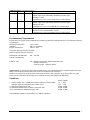
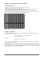
Contents Page
Chapter 1 Introduction to the LCA15F .............................................................................................. 3
Chapter 2 Installing the LCA15F ...................................................................................................... 5
Environmental Requirements ........................................................................................................... 6
Conditions .................................................................................................................................. 6
Terminal Connections .................................................................................................................... 7
Chapter 3 The LCA15F Controls & Parameters.................................................................................... 8
The Configurable Parameters........................................................................................................... 8
Configurable Parameters ................................................................................................................ 9
Chapter 4 Strain Gauge Input to the LCA15F ..................................................................................... 10
The Strain Gauge Input ................................................................................................................. 10
Hardware Configuration: ............................................................................................................... 10
Auto Calibration ......................................................................................................................... 11
Display Averaging (dA) .................................................................................................................. 11
Selection of 'Live', 'Peak' and 'Trough' (Valley) Readings .......................................................................... 12
Chapter 5 Analogue Outputs ......................................................................................................... 13
Output Scaling............................................................................................................................ 13
Method of Calculating OPL & OPH from any known output values .............................................................. 14
Calibration ................................................................................................................................ 14
Fast Analogue The (UAFAO) Module .................................................................................................. 15
Chapter 6 Relay Output Module ..................................................................................................... 16
General Description ..................................................................................................................... 16
Module Functions ........................................................................................................................ 16
Set Points (SP) ............................................................................................................................ 16
In Flight Compensation ................................................................................................................. 16
Hysteresis (HYS) .......................................................................................................................... 17
Output Action (OA) ...................................................................................................................... 17
Latching Outputs ......................................................................................................................... 17
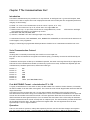
Chapter 7 The Communications Port ............................................................................................... 18
Introduction .............................................................................................................................. 18
Serial Communication Protocol ....................................................................................................... 18
Fast MANTRABUS Format - selected when CP is 128............................................................................... 18
Operation ................................................................................................................................. 18
Updating................................................................................................................................... 19
Communications Commands ........................................................................................................... 19
COMMAND Ø Request Peak/Trough and Live Displays: ............................................................................ 19
Response To Command Ø ............................................................................................................... 20
Command 1
Request for all data: ................................................................................................. 20
Response To 1 From LCA15F ........................................................................................................... 20
Command 2 Request Display Data .................................................................................................... 20
Response To Command 2 From LCA15F .............................................................................................. 21
Commands 3 To 18: Write Data To LCA15F Parameter ........................................................................... 21
Response to Command 3 to 22 ........................................................................................................ 21
Command 19: EEPROM Enable / Disable ............................................................................................. 21
Command 20: Output Relay Reset .................................................................................................... 22
Command 21: Auto Tare ................................................................................................................ 22
Command 22: Peak Hold Reset ........................................................................................................ 22
ASCII Format - selected when CP is 129 ............................................................................................. 23
Instruction Set for ASCII Serial Communications ................................................................................... 24
Modbus Protocol ......................................................................................................................... 25
LCA15F Printer Format ................................................................................................................. 26
Chapter 8 Trouble Shooting Guide .................................................................................................. 32
Chapter 9 LCA15F Specifications.................................................................................................... 33
DC Analogue Outputs .................................................................................................................... 33
Control / Alarm Relay Output ......................................................................................................... 33
The Communications Port Data ....................................................................................................... 34
Data Retention and Protection ........................................................................................................ 34
1
Mantracourt Electronics Limited LCA15F User Manual
Environmental ............................................................................................................................ 34
CE Approvals .............................................................................................................................. 34
Physical .................................................................................................................................... 34
Power Supplies ........................................................................................................................... 34
LCA15F Order Codes..................................................................................................................... 35
Instrument Setup Record Sheet ....................................................................................................... 36
W A R R A N T Y .......................................................................................................................... 36
Mantracourt Electronics Limited LCA15F User Manual
2
Chapter 1 Introduction to the LCA15F
The In Line Intelligent Strain Gauge Amplifier LCA15F is a High speed version of the LCA15 and is a compact
microprocessor based unit specifically designed to control weighing applications.
Its flexibility of design allows for the connection of most Strain Gauges, pressure or strain gauges over a wide range
of sensitivity.
Housed in a light grey, ABS case, it is sealed to IP65 standard to meet most environmental conditions.
The basic unit offers the following facilities:simple auto calibration of the highest and lowest weights required
easy auto tare setting and peak hold facility
password facility gives protection to setup parameters
DC analogue outputs of 4-20mA and 0-10V are standard with full scaling over any desired range and the ability to
invert these outputs if required
Gain sensitivity is selectable via DIL switches between 0.5 and 200mV/V.
Several 'plug in' options are available. An optional relay output module provides for 2 set points and hysteresis can
be applied to both set points together with In Flight compensation. Relays can be inverted and latched. All these
facilities being set digitally in real engineering terms from the plug in programmer unit or from an optional internal
display module. Both relay and analogue outputs have a high level of isolation.
An Optional communications modules provide for 20mA noise immune current loop, RS232 or RS485 connections to a
PC,PLC or main frame. This allows for the input variable to be viewed and any setup parameters changed.
Multiple 20mA LCA15Fs can be connected via an IF25 current loop to RS232 interface which, when included, allows
for an expansion of up to 250 LCA15Fs.
The RS232 port is available for Time/Data or data only printers to be used, logging all desired activities.
Baud speeds between 300 and 19200 are programmable.
The power supply module is available for 220/240V AC and 110/120V AC or 24/48V DC.
Further options provide the LCA15F in an IP65 die cast case for harsh environments or a PCB only (Eurocard) version
is available for customers enclosures. Two variants are available for rack mounting.
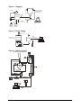
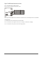
3
Mantracourt Electronics Limited LCA15F User Manual
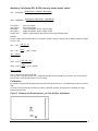
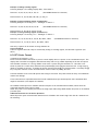
Figure 1.1 Bagging
Bagging
Hopper suspended
on 3 Strain Gauges
(only 2 shown)
Printer
Control
Output
LCA15F
100
kg
Input
PLC
Analogue
Output
10000
Remote
Indicator
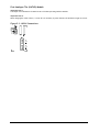
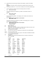
Figure 1.2 Drum Filling
Control Output
Platform placed
on 4 Strain Gauges
RS232
or 20mA Loop
LCA15F
Input
Figure 1.3 Mixing Control
RECIPEMIXING/ INGREDIENTS
Mantracourt Electronics Limited LCA15F User Manual
4
Chapter 2 Installing the LCA15F
In order to maintain compliance with the EMC Directive 2004/108/EC the following installation recommendations
should be followed.
Inputs:
Use individually screened twisted multipair cable. (e.g. FE 585 - 646)
The pairs should be :
pins 1 & 6
pins 2 & 5
pins 3 & 4
Terminate all screens at SCR. The screens should not be connected at the transducer end
of the cables.
Comm’s Port:
Use individually screened twisted multipair cable. (e.g. FE 118-2117)
the pairs should be:
-Tx & +Tx
-Rx & +Rx
Terminate screens at SCR.
The screens should not be connected at the host port.
Analogue
Output:
Use screened twisted pair cable. (e.g. RS 626-4761)
Terminate screen at SCR.
The screen should not be connected at the host port.
SCR should be connected to a good Earth. The Earth connection should have a crosssectional area sufficient enough to ensure a low impedance, in order to attenuate RF
interference.
5
Mantracourt Electronics Limited LCA15F User Manual
Cable Information (For Reference only)
Country
Supplier
Part No
Description
UK
Farnell
118-2117
Individually shielded twisted multipair cable (7/0.25mm)- 2 pair
Tinned copper drain. Individually shielded in polyester tape.
Diameter: 4.1mm
Capacitance/m: core to core 115 pF & core to shield 203 pF
UK
Farnell
585-646
Individually shielded twisted multipair cable (7/0.25mm)- 3 pair
Tinned copper drain. Individually shielded in polyester tape.
Diameter: 8.1mm
Capacitance/m: core to core 98 pF & core to shield 180 pF
UK
RS
626-4761
Braided shielded twisted multipair cable (7/0.2mm)- 1 pair
Miniature- twin -round Diameter: 5.2 mm
Capacitance/m: core to core 230 pF & core to shield 215 pF
Environmental Requirements
LCA15F units can operate in any industrial environment provided the following limits are not exceeded at the point
of installation:
Operating Temperature:
-10ºC to 50ºC
Humidity:
95% non condensing
Storage Temperature:
-20ºC to +70ºC
Two power supply options are available
Units can operate from the following:220/240V AC, 50/60Hz 10W
110V AC, 50/60Hz 10W
LS1
110/240
9-30V DC, 10W
LS3
(Running current 250 - 480mA Dependent upon
module configuration)
(start up current - 3Amps for 20mS)
Important Note To remove the power supply module using a pair of pointed nose pliers squeeze together the nylon
barbs in the two pillars fitted at the top of J2 and C10 so they become ineffective
Pull the board away from the pillar by the inter board connector. Then from pillar by J2. Remove the two nylon
pillars from the main board by twisting over in readiness for the power supply with NEW pillars.
Conditions
I. LCA15F and LP1 with 1 x 350R Strain Gauge connected, and a 4-20mA
analogue output providing 20mA into a short circuit
II. With relay module fitted, add
III. With RS232 module fitted- no device connected, add
IV. For each additional 350R Strain Gauge, add
Power in Watts
12 : 24V
2.24
2.88
0.58W 0.65W
0.07W 0.09W
0.38W 0.48W
Note: Maximum number of Strain Gauges = 6 x 350R or equivalent
Mantracourt Electronics Limited LCA15F User Manual
6
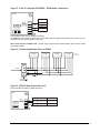
Terminal Connections
Connection between the LCA15F unit and input/output signals, including power supplies, are made via 2.5mm field
terminal blocks inside the unit.
Access to the terminals is made through glands in the bottom of the case.
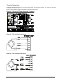
Figure 2.1 The LCA15F Field Connection Terminals
Figure 2.2 The 4 Wire Strain Gauge
Figure 2.3 The 6 Wire Strain Gauge
7
Mantracourt Electronics Limited LCA15F User Manual
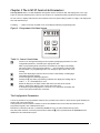
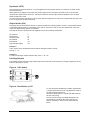
Chapter 3 The LCA15F Controls & Parameters
The Programmer Unit - Is a small hand held unit together with a connection lead, which plugs into a 'FFC' type
socket on the main assembly board. There is also an option for a permanent field programmer fitted internally.
All user controls, displays and indicators are mounted on the front panel which provides a 4.5 digit, LCD display and
four flush mounted keys .
A flashing ----- symbol in the top left hand corner of the display indicates programming mode
Figure 3.1 Programmer Unit Panel Layout
R
Table 3.1 Control Panel Guide
d
b
c
a
Used to scroll through and change the set up data by displaying mnemonics for each
configurable parameter, followed by the appropriate data.
When in programming mode it should be noted that the first digit in the display
may not be visible, but the program indicator --- will be flashing to indicate that
the instrument is in programming mode, even though no digits can be seen to be
flashing.
Selects the display digit required. Selection value is indicated by a flashing digit
and flashing program indicator
Increments each selected display digit 0-9.
Pressing the c key under programming conditions will display the leading digit as
either 1, -1, or a blank display for zero.
Resets the display to the input variable and enters new data in the LCA15F
memory. Returns the display to the current value after Hold.
If during the programming sequence, selection is not completed, the display will
revert to the input variable after 2 minutes.
The Configurable Parameters
A series of parameters or programmable functions are provided in the LCA15F to allow the user good flexibility for
monitor and control applications.
These parameters are included as constants in the LCA15F database and are accessed and checked via the
programmer keypad or the communications port.
Data which is entered by the user is retained by EEPROM for up to 10 years without back up power.
New data, when entered, overwrites previous entries when the a key is pressed unless the EEPROM has been
disabled via the communications port.
Mantracourt Electronics Limited LCA15F User Manual
8
Password Protection
A 4 digit password number must be entered. The number is accessed when 'PASS' is displayed. At this point, it is
necessary to enter either the factory set number (1111) in digit positions 2-5, or the password number specifically
ordered by the customer.
Configurable Parameters
Table 3.2
CODE
Inp
P
t
PASS
SP1
IF1
VALUE
±19999
±19999
±19999
±19999
±19999
±19999
SP2
IF2
±19999
±19999
HYS
OA
0-19999
0-31
CALL
±19999
CALH
±19999
At
dA
±19999
0-7
8-15
±19999
±19999
Decimal
Point
OPL
OPH
dP
Cp
SdSt
or
LAb
Ln
rS
InP
0-129
0-254
FUNCTION
Live input reading
Peak reading
Trough (valley) reading
Security Password. Correct value required to proceed further.
Set Point 1 'desired' trip value of output 1
In-Flight compensation for SP1
Relay 1 operates at = SP1 - IF1
Set Point 2 'desired' trip value of output 2
In-Flight compensation for SP2
Relay 2 operates at = SP2 - IF2
Hysteresis amount applied to SP1 and SP2
Output Action. Relays energise or de-energise above SP level.
Analogue output normal or inverted, and latching
Calibration Low. Display value for low calibration point(Must be
less than CALH)
Calibration High. Display value for high calibration point
Note: When CALH = 0,the LCA15F display scaling is -19999 to +19999
Auto Tare value
Display Averaging 1 to 64 standard display updates
Display Averaging 1 to 64 display updates for peak hold
Output Low (minimum) Display point for minimum analogue output
Output High (maximum) Display point for maximum analogue output
dP Position
Code
To set the required position of the
19999
0
decimal point on the display.
1.9999
1
19.999
2
199.99
3
1999.9
4
19999.
5
Comms Protocol 0 to 127 = Printer, 128 = MANTRABUS, 129 = 'ASCII'
Serial Device Station Number. This is the address code for each
LCA15F when the communications port is used.
0-255
Selects the desired label for the printer.
Log Number
Sets Display Resolution
0 & 1 = Resolution of 1 least significant digit
2-255 = Resolution setting of last digits
Input
Variable
Automatically returns the LCA15F to the input after scrolling
sequence is completed and updates permanent memory.
Note: Invalid parameter values - Should an invalid figure be entered against any parameter, it
will be rejected and the display will return to show the parameter mnemonic.
9
Mantracourt Electronics Limited LCA15F User Manual
Chapter 4 Strain Gauge Input to the LCA15F
The Strain Gauge Input
The LCA15F offers a direct connection to most low level (foil) strain gauge sensors.
The following example is for calibration of a Strain Gauge.
A 10 volt excitation is provided and it is monitored to compensate for any variation due to supply drift, load
regulation or voltage drop in the cable between the sensor and the LCA15F.
The maximum supply current is 150mA which allows for the connection of 4 x 350 Ohm Strain Gauges.
Strain Gauge sensitivity is preset via DIL switches to 0.5, 0.8, 1.0, 1.25, 1.5, 2.0, 2.5, 3.5, 5, 10, 20, 50, 100 and
200 mV/V. Select the next value higher than the Strain Gauge output maximum.
SW1 mV/V
0.5
0.8
1.0
1.25
1.5
2.0
2.5
3.5
5.0
10.0
20.0
50.0
100.0
200.0
1
x
x
2
x
x
x
-
3
x
x
x
x
-
4
x
x
x
x
x
-
5
x
x
x
x
-
6
x
x
x
-
7
x
x
x
x
-
8
x
x
x
x
x
x
x
x
-
x = ON - = OFF
mV/V = +/-mV/V nominal full range gain within +/-3%
Hardware Configuration:
The LCA15F is supplied set to +/-2.5mV/V maximum. To check if the Strain Gauge and application is within this
range, apply the following formula:
Maximum load (weight) x Strain Gauge output voltage
Strain Gauge rated range
For example:
1.5 tonne x 2.5mV/V = 1.875mV/V
2 tonne
From the resultant figure is ±2.5mV or less, then calibration can be carried out. If it is greater. Select a higher
setting with the DIL switch as necessary.
Before any calibration can be set, it will be necessary to decide upon the calibration values and place the decimal
point in the appropriate position. To do this, scroll through the parameters, entering the password as appropriate(as
described in Chapter 3), until the decimal point parameter is reached (dP-r). Once the decimal point is set, the auto
calibration parameters can be set in real engineering terms.
Mantracourt Electronics Limited LCA15F User Manual
10
Auto Calibration
Connect the Strain Gauge, switch on the LCA15F. Connect the Programmer for (RL1) version.
Allow a warm up period of 10 minutes before carrying out the procedure as follows;
a) Press the d key until PASS appears.
b) Enter the password using b and c keys, then press d key.
c) Keep pressing the d key until CALL (Cal Low) appears.
d) Press the b key and check that the program light flashes.*
*IMPORTANT NOTE: Always ensure that the programmer indicator flashes, even though the
displayed value may not need to change.
e) Check that the displayed value agrees with the low calibration weight applied to the Strain
Gauge (this may be zero).
If this is not correct, alter the display value by pressing the b & c keys.
Ensure that the Strain Gauge is free from disturbance and press the d key to capture and
calibrate the CALL value.
f) CALH (Cal High) now appears on the display.
g) Press the b key and check that the program light flashes.
h) Apply the known higher value weight.
Check that the displayed value agrees with the high calibration weight applied to the Strain
Gauge.
If this is not correct, alter the display value by pressing the b & c keys.
Ensure that the Strain Gauge is free from disturbance and press the a key. The display will
now indicate the Strain Gauge auto calibrated high value.
Note 1:
Note 2:
Note 3:
Note 4:
Note 5:
Note 6:
Note 7:
The Calibration value is not entered into the memory until either the d key or the
a key is pressed.
CALH must always be greater than CALL, in both weight and entered values.
Pressing the a key at any time will return the display to normal operation.
For best accuracy and resolution, the calibration weight should be approximately
75% of the Strain Gauge capacity.
For range check before autocal, set CAL H to O and display will be that of the A/D
counts. It is important that the A/D span between the CALL weight and CALH
weight, is greater than the span of the values entered for CALL and CALH,
otherwise the display resolution will not be 1digit.
CALH can be set before CALL if required.
CALH and CALL can be programmed individually with any time period between
provided that the a reset key is pressed to store the value.
Auto Tare
The auto tare facility allows for any unwanted weight or tare value to be compensated for in
the weighing process.
Compensation is achieved by operating a closing contact connected between the ‘AT’ terminal
and zero volts, on the field terminals.
It is possible to view the Auto Tare value by scrolling to the At mnemonic which will display the
offset present in the Auto Tare mode.
If required Auto Tare can be keypad adjusted to any desired value to give a zero or fixed
offset. adjusted to any desired value to give a zero or fixed offset.
Display Averaging (dA)
In certain applications, due to the rapid changes in the display, the least significant digits may
not be readable. In these cases, the LCA15F readings may be averaged over a number of
updates and can be set as follows:
11
Mantracourt Electronics Limited LCA15F User Manual
Table 4.1
0
1
2
3
4
5
6
7
= 1 reading (standard)
= 2 readings
= 4 readings
= 8 readings
= 16 readings
= 32 readings
= 64 readings
= Fast update mode
Display update time
approx. 0.04s
approx. 0.08s
approx. 01.6s
approx. 03.2s
approx. 06.4s
approx. 1.28s
approx. 2.56s
approx. 0.01s
Selection of 'Live', 'Peak' and 'Trough' (Valley) Readings
Any one of these readings can be chosen as the default reading, by the values placed in the (dA) -Display Averaging
mnemonics, as follows:Default 'live 'reading dA
+ Live Display averaging value
= 0-7
Default 'Peak' reading dA
+ Live Display averaging value
= 8-15
Default 'Trough' (Valley) reading dA
+ Live Display averaging value
= 16-23
The values of the three readings, are viewed by pressing the scroll d key, which will show the appropriate value for
2 minutes, after which the display will revert back to the chosen default readings.
Where an Auto Tare value and Peak/ Trough are both operative, it is important to be aware that an Auto Tare
function, although activated in the normal way, will zero the input but not the display, which will retain the
Peak/Trough value.
Mantracourt Electronics Limited LCA15F User Manual
12
Chapter 5 Analogue Outputs
Two analogue outputs are available offering a DC current range and a DC voltage range.
They are fully scalable, optically isolated and generated from the displayed input value. The 4 to 20mA output is pre
calibrated to an accuracy of within 0.15% of the range. The 0-10V output is accurate to within 2% of the 4 to 20mA
output.
OUTPUT
DC voltage
DC current
RANGE
0V to 10V
4 to 20mA
Notes:
1. Maximum current load on voltage modules is 2mA
2. Maximum drive voltage available in current modules is 20V
3. Response time from 33% step input to settle within 1% of final value = 40mS
4. When a Fast Analogue Output Module is fitted set the OA mnemonic to 32
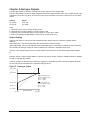
Output Scaling
Output scaling factors are set by the user and determine the display range over which the analogue module
operates.
(OPL) Output Low - This sets the displayed value at the module's minimum output.
(OPH) Output High - This sets the displayed value at maximum output. If the display is outside the range defined by
OPL and OPH, the analogue output will remain constant at its minimum or maximum output value.
Inversion of the analogue output can be set by the output action mnemonic OA (See Relay Output Module Chapter
6).
Example: Assume a 4-20mA output module is required to provide an output of 4mA for 1000Kg and 20mA for 6500Kg.
Set OPL to 1000 and OPH to 6500
It will be necessary to determine OPL and OPH by graphical or mathematical means if the known display values do
not coincide with the minimum and/or maximum analogue output.
Figure 5.1 Analogue Output
Max +19999
OP HI=6500
Output scaled over the
complete display range ie
OP HI = +19999
OP LO = -19999
OP LO 1000
Output scaled over the
complete display range ie
OP HI = +6500
OP LO = +1000
Display = 0
Min -19999
Min 4mA
13
Analogue Output
Max 20mA
Mantracourt Electronics Limited LCA15F User Manual
Method of Calculating OPL & OPH from any known output values
DisplaySpan * (LowOutput − MinOutput )
OPL = LowDisplay −
(HighOutput − LowOutput )
DisplaySpan * (MaxOutput − HighOutput )
OPH = HighDisplay +
(HighOutput − LowOutput )
Low output =
High output =
Min output =
Max output =
Display span =
Known low output
Known high output
Lowest measurable value of output module
Highest measurable value of output module
Highest required display value minus lowest required display value.
Example:
Using a 4.20mA output module where it is required to produce 6mA at a display value of 400 and 18mA at a display
value of 1100.
700 * (6 − 4)
OPL = 400 −
(18 − 6)
1400
OPL = 400 −
= ( 400 − 116.66)
12
OPL = 283.33
700 * ( 20 − 18)
OPH = 1100 +
(18 − 6)
1400
OPH = 1100 +
= (1100 + 116.66)
12
OPH = 1216 .66
Note 1: OPH must be greater than OPL
Note 2: If OPL or OPH are greater than ± 19999 then divide both OPL and OPH by 10, this will give less resolution.
Decimal point can be placed anywhere to suit reading.
Calibration
Re calibration can be made by adjusting the gain and offset potentiometers, or by adjusting the values of OPL and
OPH.
An offset can be achieved by increasing the values of both OPL and OPH, and the gain by increasing the range
between OPL and OPH.
Figure 5.2 Showing the Potentiometers for Gain & Offset Adjustment
GAIN
ADJUST
OFFSET
ADJUST
Mantracourt Electronics Limited LCA15F User Manual
14
Fast Analogue The (UAFAO) Module
Important Note 1:
The output action mnemonic OA must be set to 32 when operating with this module.
Important Note 2:
When changing the value of OA to, or from '32' it is necessary to power the unit off and back on again as a reset.
Figure 5.3 - UAFAO Connections
15
Mantracourt Electronics Limited LCA15F User Manual
Chapter 6 Relay Output Module
General Description
The Relay output module provides output control signals which can be used for switching functions such as ON/OFF
control and alarm indications. The relays are activated by the values programmed for the Set Points. The output
configuration will be for open or closed relay contacts and latching.
Output
Function
2 Relays
SPCO on SP1 and SP2
The connections for which are shown in Chapter 2
Module Functions
The LCA15F can be programmed so that the relay output module reacts to all or any of the following functions:
•
•
•
•
•
Set points
In Flight compensation
Hysteresis
Relay inversion
Latching
Set Points (SP)
Set points are used to produce output signals at any required value so that the operation of the monitored process
can be maintained to preset levels. Any excursion beyond set points will activate the relay or relays, to provide
alarm or initiate control as required.
Two set points (SP1) and (SP2) can be programmed to suit different applications. The actions of either or both set
points can inverted if required.
For normal operation the set point output is active until the input reaches the set point level. In this condition when
the input value is less than the set point, the SP indicator is on and the output relay is energised producing a closed
circuit on a normally open contact. When the set point value is reached ,the SP indicator is off and the relay is deenergised producing an open circuit output.
For an inverted operation the reverse conditions apply.
Normal and inverted action is determined by the direction of the input value as it changes.
For example: In alarm applications.
A High-High operation allows for a rising input value to operate on two set points to define an acceptable quantity,
weight or band of operation.
A Low-Low operation operates on a falling value.
A High-Low operation will operate on a rising or falling value, setting a 'band' by one set point operating normally
and the other being an inverted action.
In Flight Compensation
The setting of an In Flight value causes the set points to automatically adjust to control the flow of the material
being weighed.
For example, if SP1 is used to control a flow, a certain amount will be 'In Flight' between the supply point and
receiving point causing a positive error when the required weight is reached. The In Flight compensation value is
adjusted by the user to 'reduce' SP1 to prematurely stop the flow, allowing the In Flight amount to make up the
required total set by SP1. A similar situation exists for SP2.
Mantracourt Electronics Limited LCA15F User Manual
16
Hysteresis (HYS)
Once a Hysteresis value has been set, it will be applied to both set points entered. It is effective for both normal
and inverted action.
When Hysteresis is applied to set points with normal output action, the input is allowed to rise to the set point
value and the output is then turned off. The output is held off until the input value has dropped to the set point
minus the Hysteresis value.
For inverted action the input drops to the set point and the output goes off and comes on again when the input rises
to the set point plus the Hysteresis value.
Output Action (OA)
The Output Action facility allows the user to determine whether set points produce normal or inverted and latched
or unlatched output operation. The Output Action (OA) is entered by a code to suit the requirements of the user.
Thirty two Output Action options are available.
The value of the OA to be entered in the algebraic sum of the following components:SP1 Inverted
SP2 Inverted
AN-OP Inverted
SP1 Latched
SP2 Latched
Fast Analogue Output
=
=
=
=
=
=
1
2
4
8
16
32
Example 1:
If SP1 requires to be latched and inverted and the analogue output is normal,
enter 8 + 1 = 9
Example 2:
To invert the analogue output and latch SP2, enter 4 + 16 = 20
Latching Outputs
The latching facility allows the relay module output to be held until reset externally. Latching is applied to the off
status of the relay SP1 or SP2.
Figure 6.1 LR1 Module
Figure 6.2 Installation of LR1
To meet the Specified EMC Fast transient requirements
it is important that the ferrite ring supplied is fitted as
per the following instructions.
Illustration showing ferrite ring FEC 323-4940 fitted to
the LR1 relay wiring.
Two turns of the wiring are passed through the ring
positioned 12cm from the LR1 end of the cable to
improve immunity to electrical fast transients and
bursts.
17
Mantracourt Electronics Limited LCA15F User Manual
Chapter 7 The Communications Port
Introduction
The LCA15F communications port provides for a 2 way data link. An intelligent host e.g. Personal Computer, Main
Frame or PLC is able to acquire the LCA15F’s displayed value and read or modify the user configurable parameters,
using any of the following:a) RS232 - for a one to one communication (as in the case of a printer, PC or PLC).
b) RS485 - for the connection of up to 25, LCA15F units on a single RS485 line.
c) 20mA Current Loop - for up to 250, LCA15F units on a single RS232 line, via the
noise immunity and isolation over distances up to 1Km.
d) Baud Rates 300, 600,1200,4800, 9600
e) Isolation ± 130V RMS or DC max to analogue input or any other port
IF25 interface. With high
4 communication formats, FAST MANTRABUS, ASCII, MODBUS RTU and PRINTER, are selected from the mnemonic CP
via the keypad, of the programmer.
Integrity is ensured by pre-programmed default parameters should a loss of communications with the host occur.
Serial Communication Protocol
General
Incoming data is continually monitored by the LCA15F on its serial input line.
Each byte of data is formatted as an eight bit word without parity, preceded by one start bit and followed by one
stop bit.
Transmission and reception of data up to 19.2K Baud is possible, the actual rate being selected by an eight-position
slide switch on the communications module (of which only 7 positions are used). The Baud rate depends upon the
communications, hardware specification, distance and cable type.
Position 1
Position 2
Position 3
Position 4
Position 5
Position 6
Position 7
=
=
=
=
=
=
=
300
600
1200
2400
4800
9600
19200. (FAST MANTRABUS ONLY)
Fast MANTRABUS Format - selected when CP is 128
To signify commencement of a new 'block' of data, the HEX number FFH is used as a 'frame' character, followed by
the station number of the unit under interrogation. This is entered via the LCA15F keypad under mnemonic SDSt and
ranges from 0-254).
The LCA15F acts upon incoming data only if its own station number immediately follows the FFH character.
New data must be received as a string of four nibbles (bits 7-4 set to zero) which are assembled into two bytes and
written into the variables store within the LCA15F. The most significant nibble must be received first and the last
nibble must have the most significant bit (bit 7) set to indicate the end of data. This is followed by the checksum.
The data transmitted from the LCA15F is always sent as complete bytes. The station number precedes the data and
the checksum follows the data. The data format used is signed 15 Bit. The most significant Bit of the most
significant Byte is set for negative numbers.
Operation
There are two modes of operation, namely data requests by the host controller and data changes. Data requests
from the LCA15F consist of either a complete dump of the data variables stores in RAM or the display reading.
Mantracourt Electronics Limited LCA15F User Manual
18
Data changes consist of writing new data to LCA15F variables, thus changing parameters such as Set Points, in
flights etc.
An acknowledgement message is returned to the LCA15F to indicate that the new data has been acted upon.
Updating
The required mode or variable to be updated is determined by the station number followed by the command byte.
An EXOR checksum consisting of the station number command byte and any following data must be appended to the
received data. It is most important that the byte proceeding the checksum must have its most significant bit set to
signify the end of data.
The LCA15F works out its own checksum and, if it disagrees with the received one, a not acknowledge (NAK)
message is returned.
Communications Commands
The following is a list of commands available for reading to or writing from the LCA15F.
COMMAND No.
DESCRIPTION
HEX
DEC
REQUEST ALL DATA INCLUDES WEIGHT INPUT
1
1
REQUEST DISPLAY DATA
2
2
UPDATE SET POINT 1 (SP1)
3
3
UPDATE IN-FLIGHT 1 (IF1)
4
4
UPDATE SET POINT 2 (SP2)
5
5
UPDATE IN-FLIGHT 2 (IF2)
6
6
UPDATE HYSTERESIS (HYS)
7
7
UPDATE OUTPUT ACTION (OA)
8
8
RESERVED
9
9
RESERVED
A
10
RESERVED
B
11
RESERVED
C
12
UPDATE AUTO TARE (At)
D
13
UPDATE DISPLAY AVERAGES AND HOLD FUNCTION (dA)
E
14
UPDATE OUTPUT LOW (OPL)
F
15
UPDATE OUTPUT HIGH (OPH)
10
16
UPDATE DECIMAL POINT AND RESET FUNCTION (DP r)
11
17
CAN NOT BE WRITTEN TO, AND LCA WILL RETURN A NAK (SDSt/CP) EEPROM
12
18
ENABLE/DISABLE
13
19
OUTPUT RELAY RESET
14
20
AUTO TARE
15
21
PEAK HOLD RESET
16
22
COMMAND Ø Request Peak/Trough and Live Displays:
Data transmission to LCA15F for Command Ø , ØFFH, Station Number, Ø8ØH, CHKSUM.
Where CHKSUM = Station Number EXOR with 8ØH
Example: To obtain Live, Peak/Trough value of the LCA15F whose Station Number is 47 send the following data:ØFFH, Ø2FH, 8ØH, ØAFH
Note MS Bit Set
19
Mantracourt Electronics Limited LCA15F User Manual
Response To Command Ø
Byte
1
2,3
4,5
6,7
8
Station Number
Live reading
Peak reading
Trough reading
EXOR CHKSUM of above data
Command 1 Request for all data:
DATA TRANSMITTED TO LCA15F FOR COMMAND 1
0FFH, Station Number, 081H, Chksum
Where Chksum = Station number EXOR with 081H.
Example:
To obtain a complete dump of the variables in the LCA15F whose Station number is 47 send the following Data:0FFH, 02FH, 081H, 0AEH
Note MS Bit Set
Response To 1 From LCA15F
Byte
1
2,3
4,5
6,7
8,9
10,11
12,13
14,15
16,17
18,19
20,21
22,23
24,25
26,27
28,29
30,31
32,33
34,35
36
37
38
Station number
DISPLAY
SET POINT 1
IN FLIGHT 1
SET POINT 2
IN FLIGHT 2
HYSTERESIS
OUTPUT ACTION
A/D COUNTS FOR LOW CALIBRATION POINT
A/D COUNTS FOR HIGH CALIBRATION POINT
DISPLAY LOW CALIBRATION VALUE
ISPLAY HIGH CALIBRATION VALUE
AUTO TARE
DISPLAY AVERAGING
OUTPUT LOW
OUTPUT HIGH
DECIMAL POINT POSITION
STATION NUMBER
EEPROM ENABLE/DISABLE FLAG
RELAY STATUS
EXOR CHECKSUM OF THE ABOVE DATA
NOTE: Most significant byte proceeds least significant byte for data sent by LCA15F.
Command 2 Request Display Data
DATA transmitted to LCA15F for Command 2.
0FFH, Station number, 082H, Chksum
Where Chksum = Station number EXOR with 082H
Example:
To obtain the display reading of an LCA15F whose station number is 47 send the following Data:
Mantracourt Electronics Limited LCA15F User Manual
20
0FFH, 02FH, 082H, 0ADH
Note MS Bit Set
Response To Command 2 From LCA15F
BYTE
1. Station No.
2. Display reading M.S. Byte.
3. Display reading L.S. Byte.
4. EXOR checksum of above data and Station No.
If, when using commands 1 or 2, an error is detected by the LCA15F then the Not Acknowledgement string is
transmitted by the LCA15F.
Commands 3 To 18: Write Data To LCA15F Parameter
Commands 3 to 18 all have the same format.
Format for data transmitted to LCA15F for Commands 3 to 18:0FFH, Station No, Command No, MSN, NMSN, NLSN, LSN, CHKSUM
= Most significant nibble of data
Where MSN
= Next most significant nibble of data
NMSN
= Next least significant nibble of data
NLSN
LSN
= Least significant nibble of data with MSBIT set
CHKSUM
= The following EXOR’d with each other, Station number,
command number, MSN, NMSN, NLSN, LSN with MSBIT set
Example: To change SP1 to 200.0 on an LCA15F whose station number is 47. The following data is sent.
Please note the following points apply:1. The decimal point is ignored i.e. 200.0 equals 2000 digits
2. The data is sent in Hex nibbles so 2000 = 00H, 07H, 0DH, 00H
0FFH,02FH, 03H, 00H, 07H, 0DH, 80H, 0A6H
Note MSBIT set
Response to Command 3 to 22
If the data has been accepted by the LCA15F then the following acknowledgement string is transmitted by the
LCA15F.
Station number, 06H (ACK)
If there are any errors with the data received by the LCA15F then the following
Not Acknowledgement (NAK) string is transmitted by the LCA15F:Station number, 015H (NAK)
Command 19: EEPROM Enable / Disable
The EEPROM disable facility can be used for any of the following:
I. To limit the number of write cycles to EEPROM reducing degradation.
II. Change data in the LCA15F RAM only, allowing EEPROM to hold power up values.
III. Leave base constants in the EEPROM for later update to RAM which allows
manipulation of the data before writing to the RAM.
Writing new data from the RAM to the EEPROM.
EEPROM disable is achieved by writing 0100H to the LCA15F via command 19. In this state all writing to, or reading
from the EEPROM is inhibited.
21
Mantracourt Electronics Limited LCA15F User Manual
The EEPROM can be re-enabled in two ways:
By writing 0200H via command 19.
This writes the current contents of the variables store in the LCA15F into the EEPROM.
By writing 0400H via command 19.
This updates the variables store from the current contents of the EEPROM.
Examples:
To disable the EEPROM on an LCA15F whose Station number is set to 47
0FFH 02FH 013H 00H 01H 00H 080H 0BDH
To re-enable the EEPROM and update the RAM with the old EEPROM constants:
0FFH 02FH 013H 00H 04H 00H 080H 0B8H
To re-enable the EEPROM and update it with the new RAM data:
0FFH 02FH 013H 00H 02H 00H 080H 0BEH
For response see 'Response to Command 3 to 22'.
Command 20: Output Relay Reset
DATA transmitted to LCA15F for Command 20
OFFH, Station number, 094H, CHKSUM
Where CHKSUM = Station Number EXOR with 094H
Example: To output a relay reset to an LCA15F whose
Station Number is set to 47
0FFH, 02FH, 094H, 0BBH
Note MS BIT SET
For response by LCA15F see 'Response to Commands 3 to 22'
Command 21: Auto Tare
DATA transmitted to LCA15F for Command 21
OFFH, Station number, 095H, CHKSUM
Where CHKSUM = Station Number EXOR with 095H
Example: To output an Auto Tare command to an LCA15F whose
Station Number is set to 47
0FFH, 02FH, 095H, 0BAH
Note MS BIT SET
For response by LCA15F see 'Response to Commands 3 to 22'
Command 22: Peak Hold Reset
DATA transmitted to LCA15F for Command 22
OFFH, Station number, 096H, CHKSUM
Where CHKSUM = Station Number EXOR with 096H
Example: To output a Peak Hold reset to an LCA15F whose
Mantracourt Electronics Limited LCA15F User Manual
22
Station Number is set to 47
0FFH, 02FH, 096H, 0B9H
Note MS BIT SET
For response by LCA15F see 'Response to Commands 3 to 22'
Example of a Basic Code to Communicate with Fast MANTRABUS
open the serial port with no handshaking
OPEN"COM2:4800,N,8,1,RS,DS,BIN" FOR RANDOM AS#1
request display from device 1
Frame FF
Station No
Command 2
Checksum of
1
And add 80 hex
to this byte as it
is the last before
as the checksum
all bytes except frame
talk$=CHR$(&HFF)+CHR$(&H1)+CHR$(&H82)+CHR$(&H1 XOR&H82)
print the string to the port
PRINT#1,talk$;
(must add semicolon after string to stop transmitting a carriage return)
wait for a while (this depends on how many bytes you are expecting and the baud rate!)
input all the bytes in the serial buffer
input.from.lca15f$=INPUT$(LOC(1),#1)
ASCII Format - selected when CP is 129
The serial data to and from the LCA15F is formatted as eight bit words with no parity preceded by one start bit and
followed by one stop bit. The baud rate (up to 9.6k Baud) is selected on the COMMS module. All communications are
carried out using the standard ASCII character set. Incoming line feeds and spaces are ignored; upper and lower case
letters are permitted. The incoming data is continually monitored for Carriage Return characters (Chr$13D). If one is
received the next three characters (000 - 999) are compared with the LCA15F station number (SDST) previously
entered via the keypad. N.B. leading zeros must be included. If no match is found the data that follows is ignored.
The next characters received (up to 4 max) are decoded as the 'label', i.e. which variable in the LCA15Fis to be
acted upon. If the label is received incorrectly and cannot be decoded the LCA15F will return a '?' followed by a C.R.
character. If the received label is followed by a C.R. the LCA15F will return the current value of the variable in
question. (Because there is no hardware handshaking, all transmission from the LCA15F is performed one
character at a time upon receiving a Null character (Chr$0) prompt from the Host system. Thus for every
character transmitted a prompt character is required. ) The output from the LCA15F is an ASCII string of sixteen
characters the last one being C.R.
The first four characters are the Station No. (with leading zeros if necessary) followed by a space. The label then
follows with spaces added if required to make a total of four characters. The next seven characters is the numerical
value of the required variable with polarity, spaces, d.p. and leading zeros added as required.
If the received label is followed by an '=' character the LCA15F accepts the following numerical data (which must be
terminated by a C.R.) and updates the variable in question and returns a C.R. character to the host when prompted.
Data input is reasonably flexible. If all five digits are entered, no decimal point need be included. If less than five
digits are entered with no decimal point then the last digit is assumed to be the units.
Under normal circumstances the EEPROM in the LCA15F continually refreshes the working RAM. However, it can be
disabled via the serial input, by sending the instruction 'DROM = 256' after the Station No. In this condition all
read/write operations to or from the EEPROM are inhibited. There are two instructions which will re-enable the
EEPROM:
23
Mantracourt Electronics Limited LCA15F User Manual
1) 'ERRD' - this performs a read from the EEPROM and updates the working RAM with the contents of the EEPROM.
2) ‘ERWR' - this instruction writes the new RAM values into the EEPROM.
In both cases the EEPROM continues to refresh the RAM.
Instruction Set for ASCII Serial Communications
Request for data:
DATA sent to LCA15F
Data returned from LCA15F
CR xxx
DISP
CR
Station No.
label
CR xxx
DOSP
Station No.
incorrect label
CR
xxx 'SPACE'
DISP
YYYYYY CR
Station No.
label
numerical value
xxx 'SPACE'
DOSP
'SPACE' ? CR
Station No.
incorrect
label
DATA sent to LCA15F
CR xxx
Station No.,
Data returned from LCA15F
SP1 = 100.0
label numerical value
CR xxx
Station No.,
SP3 = 100.0
?CR
incorrect label, numerical value.
CR
Table 7.1
Labels
DISP
SP1
IF1
SP2
IF2
HYS
OA
At
DA
OPL
OPH
DP
SDST
DROM
ERRD
ERWR
RLYS
RES
TARE
PKR
DESCRIPTION
REQUEST DISPLAY READING
SET POINT 1 (SP1)
IN-FLIGHT 1 (IF1)
SET POINT 2 (SP2)
IN-FLIGHT 2 (IF2)
HYSTERESIS(HYS)
OUTPUT ACTION (OA)
AUTO TARE(At)
DISPLAY AVERAGES (dA)
OUTPUT LOW (OPL)
OUTPUT HIGH (OPH)
DECIMAL POINT (dP r)
CAN NOT BE WRITTEN TO (SDST/CP)
DISABLE EEPROM (DROM = 256)
ENABLE EEPROM AND READ FROM IT
ENABLE EEPROM AND WRITE TO IT
OUTPUT RELAY STATUS ( 0 = BOTH OFF, 1 = RELAY 1 ON, 2 = RELAY 2
ON, 3 = BOTH RELAYS ON)
OUTPUT RELAY RESET
AUTO TARE
PEAK HOLD RESET
Mantracourt Electronics Limited LCA15F User Manual
24
Modbus Protocol
This Modbus protocol has been implemented in accordance with Modicon Modbus
Protocol Reference Guide P1 - MBUS - 300 Rev C. With the following conditions applying.
The following conditions apply
Baud Rate must be set for 9600
The format is Modbus RTU
UART’s shall be set for 8 bit word, 1 start, 1 stop & no parity
Data is considered to be half duplex using 2 or 4 wire medium.
To Select Modbus Protocol Set CP = 130
Modbus states a new framing character is assumed after the time period to receive 3.5 characters (3.65mS) has
elapsed. As a dedicated timer is not available for this function this time value has been increased to 25mS. This
means the master must not transmit a new message until 25mS after the previous message last byte has been sent
The instrument only uses 3 commands. Read holding register , Preset single register & Preset multiple registers .
Read holding register & Preset multiple registers is limited to reading a single register .
Data is sent & returned as signed 15 bit ie 1000 = 03E8 & -1000 = 83E8.
Broad cast commands are not supported.
Exception Responses
The following exception codes will be supported only,
01 Illegal function
02 Illegal data address
03 Illegal value
Register Allocation
Register
No.
1
2
3
4
5
6
7
8
9
10
11
12
13
14
15
16
17
18
19
20
100
101
102
103
104
25
Mnemonic
Display (net)
SP1
IF1
SP2
IF2
HYS
OA
ADCALL
ADCALH
CALL
CALH
AT
DA
OPL
OPH
DP
CP
SDST
RS
STATUS
AutoTare
Relay Reset
Disable EEROM
Enable RAM from EEROM
Enable EEROM from RAM
Mantracourt Electronics Limited LCA15F User Manual
Example of reading a holding register.
Following example is for reading “Display (Net)” from station 1
Data sent = 01, 03, 00, 01, 00, 01, D5, CA
(See MODBUS manual for reference)
Data returned = 01, 03, 02, MSB, LSB, CRC_HI, CRC_LO
Example of writing a holding register (Command 06).
Following example is for writing “IF1” = 1200 digits to station 1
Data sent = 01, 06, 00, 03, 04, B0, 7A, BE
(See MODBUS manual for reference)
Data returned = 01, 06, 00, 03, 04, B0, 7A, BE
Example of writing a holding register (Command 16)..
Following example is for writing “IF1” = 1200 digits to station 1
Data sent = 01, 10, 00, 03, 00, 01, 02, 04, B0, CRCHi, CRCLo
(See MODBUS manual for reference)
Data returned = 01, 10, 00, 03, 00, 01, B0, CRCHi, CRClo
Note only 1 register can be written to using command 16
Action Commands
These are registers above 99. They are executed by writing to a holding register, the data sent is ignored. (See
table.)
LCA15F Printer Format
(CP must be set between 0 - 127)
Printer selection enables the LCA15F to print its current display value to a printer via its communications port. This
display value can either be assigned a date and time stamp and/or a log number depending on the user set options
entered under mnemonic 'CP'. The log number can be reset or preset using the mnemonic 'Ln'. This value is not
saved on power fail. A label can be suffixed to the printed display value using the mnemonic 'LAb'. A large range of
labels are available to the user. To initiate the printer function press the b key followed within 1 second by the d
key. The printer function can also be initiated from remote contact by adding 32 to dP r.
The time and date are set in the TDP printer itself using its own menu. The printer allows the entry of an additional
custom text message.
Three connections are required between the LCA15F communications port and the printer with a maximum cable
length of 100 metres. (See Chapter 8 for Details)
All standard LCA15F options are available with the exception of the communications modules, which cannot be
connected when the printer option is used.
NOTE: The printer is not isolated from the Strain Gauge input. When using RS232 module the printer is not isolated
from the input.
Additional Mnemonics for the Printer Operation:
When the printer option is fitted further mnemonics are included in the normal range. After the dP r mnemonic are
the following:-
Mantracourt Electronics Limited LCA15F User Manual
26
CP
At this mnemonic the printer type and print format number is selected. This number
being
appropriate to the type of printer used. Details are advised with each type of printer
selected.
Present types available are:- For the ITT IPP-144-40E printer the following numbers apply
0
Prints a sequential log number with the current display and unit of measure
e.g.
00014 0011.3 tonne
1
2
Prints date and time with a sequential log number, current display and unit of
measure
e.g.
00015 0001.7 tonne
13.07.99 12:05:06
3
Prints a sequential log number, current display, unit of measure with customer text
message No 1
e.g.
MANTRACOURT ELECTRONICS LCA15F PRINTER
00012 000.2 tonne
Prints date and time with a sequential log number, current display, unit of measure
and a customer text message No.1
e.g.
MANTRACOURT ELECTRONICS LCA15F PRINTER
00013 0023.6 tonne
13.07.99 12:03:04
4-7
8,9
Digitec 6700 series
Amplicon AP24 and AP40
Eltron LP2142 - (The label file must be called 'MEL' and the label must contain a LOG
NUMBER, THE DISPLAY VARIABLE & a LABEL (not zero).
ASCII string on print command
Continuous ASCII stream of the display data, transmitted on every display update
12
127
Note:1
Note: 2
LAb
9 gives an inverted print out
it is anticipated that further types of printer will be added, and additional numbers
will be allocated as appropriate
Label Number
A number can be selected for the appropriate unit of measure. See table below:
Note: 0 = NO LABEL
0 BLANK
1 Deg R
2 Deg C
3 Deg F
4 Kelvin
5 Ib/in 2
6 bar
7 mbar
8 kPa
9 atm
10 mmHg
11 inHg
12 inH2O
13 cmHg
14 mm
15 Wh
16 Db
17 tonne
18
19
20
21
22
23
24
25
26
27
28
29
30
31
32
33
34
m
in
ft
degrees
L/s
L/min
L/h
gals/s
gal/min
gal/h
%RH
gram
kg
lb
kWh
mile/h
%
35 ton
36 %Dev
37 W
38 kW
39 MW
40 pH
41 ppm
42 uS
43 Ohms
44 m/s
45 ft/min
46 RPM
47 RPMx10
48 RPMx100
49 cos @
50 km/h
51 ms
Ln
27
Log Number
Mantracourt Electronics Limited LCA15F User Manual
52
53
54
55
56
57
58
59
60
61
62
63
64
65
66
67
68
RPM1000
Hz
kHz
V DC
mV DC
A DC
mA DC
V AC
mV AC
A AC
N
spare
spare
spare
spare
knots
s
A range of numbers 0 to 19,999 is available. Any sequential number logging
activity can be preset as desired, between these numbers. The number will
reset to zero after 19,999. The log number is not saved on power fail
and resets to zero on power up.
Provision is made in the LCA15F for communications via one of TWO module options:
LC1
The 20mA current loop module, for connection to an IF25 interface.
LC3
An RS232/485 isolated module, for connection to a PC or PLC, in a single or multiple function
Mantracourt Electronics Limited LCA15F User Manual
28
Connections for these options are shown below:-
Figure 7.1 LC1 Current Loop
Figure 7.2 Connecting Multiple LCA15Fs
Connecting Multiple LCA15Fs to the IF25 Interface
Notes
1) Maximum loop voltage is 50V dc.
2) Loop is isolated from host and LCA15Fs. Loop should be earthed via Rx - on IF25/254
3) IF25 used for up to 25LCA15Fs.
4) At 19,200 Baud, max. cable length is 100m metres, using cable type BICC H8085.
LC3 Isolated RS232/484
29
Mantracourt Electronics Limited LCA15F User Manual
Figure 7.3 The LC3 Isolated RS232/485 - RS485 Mode Connections
LC3
LK2
Signal
LK1
Tx+
Rx+
RxTx+
Tx-
19200
9600
4800
2400
1200
TxRx+
RxSCR
The SCR must not be used for RS232 connections.
For RS485 the SCR connection on the LC3's can be daisy chained together and connected to a screen or 0v if
available from the 'masters' RS485 comms port.
When multi-dropping in RS485 mode - The last device only should be fitted with LK2, which acts as a 120R
terminating resistor.
Figure 7.4 Connecting Multiple Units on RS485
COM1/1
+ Tx Tx
+
Rx
COM1/2
Rx
+ Tx Tx
+
Rx
COM1/3
Rx
+ Tx Tx
+
Rx
Rx
COM1/X
+ Tx Tx
+
Rx
Rx
Fit LK2 in
last device
RS232
Figure 7.5 RS232 Mode Connection to PC
Note: LK21 Must be made for RS232 operation
LC3
LK2
19200
9600
4800
2400
1200
LK1
Signal
Tx+
TxRx+
RxSCR
9 Way ‘D’ Skt
25 Way ‘D’ Skt
GND
5
7
Rx
2
3
Tx
3
2
Mantracourt Electronics Limited LCA15F User Manual
30
Figure 7.6 RS232 Mode Connection to Printer
Note 1: LK21 Must be made for RS232 operation
Note 2: If no RTS is available from the printer, fit LK2
LC3
LK2
Signal
19200
9600
4800
2400
1200
LK1
Tx+
Tx-
GND
ITT-Ipp-144
-40E
1&5
Amplicon
AP24/AAP40
15
Rx
2
3
RTS
8
P
Rx+
RxSCR
NOTE:
When using an RS232 to RS485 converter which has a non-biased receiver, the following actions are recommended:To bias the device:
1) Terminate the receiver with 140R in place of the usual 120R
2) Fit a 1.5K from the receive negative to the receiver +5V supply, or a 3K3 to the +12V supply.
3) Fit a 1.5K from the receive positive to the receiver supply Ground.
31
Mantracourt Electronics Limited LCA15F User Manual
Chapter 8 Trouble Shooting Guide
This chapter is designed to assist in the identification of problems relating to the installation and setting up of the
LCA15F.
1. General Connection and setup parameters. - No display on power up.
a) Check supply is present at the LCA15F terminals.
Display shows (-1 or 1) continually, without a weight applied to the Strain Gauge.
a) Check input connections to the LCA15F from the Strain Gauge.
b) If connecting a 4 wire device ensure terminals 1&2 and 5&6 are linked.
c) Check Strain Gauge output between input terminals 3&4 of the LCA15F.
d) Check that the CALH weight is applied and is not the same or lower than CALL
Display over ranges (-1 or 1) when, or before, the maximum required weight is applied to the Strain Gauge.
a) Check output of Strain Gauge is set to the correct sensitivity settings on the DIL switch
Display very noisy
a) If using a 4 wire device ensure terminals 1&2 & 5&6 are linked.
b) Check output voltage of Strain Gauge.
Display operating in wrong direction
a) Check connections to input terminals 3&4 are correct way round.
b) Check the type of Strain Gauge - compression or tension.
Unit will not auto calibrate
a) Check that CALH is not zero and its weight is greater than CALL.
b) Check that input is not overranged on CALH weight.
Access to parameters not possible beyond the PASSWORD (PASS)
a) Check for special password if not (1111) with your company or Mantracourt. (Quote serial number as a
reference.)
2.
a)
b)
c)
Relay Output Module - Incorrect Relay Operation
Check set point, in flight and hysteresis values are correct.
Check latching and invertion settings in output action (OA) are correct.
Check connections to output terminals.
3. MANTRABUS / ASCII Format
No Communications
a) Check that a comms module is fitted.
b) Check correct CP code is entered for required protocol.
c) Check connections to LCA15F from IF25 are correct.
d) Check IF25 green LEDs are on and RX LED is on and TX LED is off.
Press TX TEST, TX LED should light.
e) Check RS232 connections from the host to the IF25 are correct.
f) Check SdSt, serial device station number is correct.
g) Check Baud rate settings on LCA15F's are correct for the host.
h) Check host comms port is set to 8 bit word, 1 start bit, 1 stop bit, no parity.
i) Check correct protocol is being observed by the host.
Mantracourt Electronics Limited LCA15F User Manual
32
Chapter 9 LCA15F Specifications
Strain Gauge Input
Calibration
Automatic digital by use of keypad and 1 (or 2) known weights.
Auto Tare
Auto Tare values can also be viewed and manually changed if required.
Auto tare value is retained on power down. Auto Tare is affected from the
field terminals.
± 0.05 to 200mV/V (Factory set to nom 2.5mV/V).
(DIL Switch Selectable) Preset to ±2%
Sensitivity Range
Excitation
Compensation
9V6 DC nominal, 160mA maximum
By ± sense wires to compensate for cable, connection
volt drops and any variation in 10V supply.
Accuracy after
user Autocal
Temp. Drift
90 days ± 0.08% of reading ± 0.05% of FSD typical
Display Rate
Programmer keypad selectable between 0.01 and 2.56 seconds.
Display Average
Set by programmer keypad, up to 64 standard updates
Frequency
Response
Strain Gauge input to analogue output - 3dB point = 13.5hz
0.002% /C typical @ 2.5mV/V
DC Analogue Outputs
Range
MIN
MAX
Max Drive
Capability
+4
0
+20mA
+10V
20V (1K)
2mA
Isolation:
±130V RMS or DC to any other port
Typical
% of
reading
± 0.1%
± 0.1%
Accuracy
% of FSD
± 0.1%
± 1%
0-10V can be calibrated by offset and gain pots if required or alternatively PL and OPH.
Response time from step input to within 1% of final value = 40mS
Control / Alarm Relay Output
2 SPCO relays, SP1 and SP2
Contact Rating 240V @ 5A AC
Setpoint, In Flight Compensation, Hysteresis, Latching and Relay Inversion are set digitally using programmer keypad
and display, in engineering units.
Hysteresis value applies to both SP1 and SP2.(Fail safe operation by setting inversion to give normally energised
operation).
Latching Reset By volt free contact to field terminals or by communication.
33
Mantracourt Electronics Limited LCA15F User Manual
The Communications Port Data
Operation
All LCA15F display data can be retrieved via communications port along with relay and EEPROM status.
All LCA15F user configurable data can be changed including EEPROM enable/display and relay reset. (LCA15F Station
Number cannot be changed).
The LCA15F communications port provides for a 2 way data link. An intelligent host e.g. Personal Computer, Main
Frame or PLC is able to acquire the LCA15F’s displayed value and read or modify the user configurable parameters,
using any of the following:a) RS232 - for a one to one communication (as in the case of a printer, PC or PLC).
b) RS485 - for the connection of up to 25, LCA15F units on a single RS485 line.
c) 20mA Current Loop - for up to 250, LCA15F units on a single RS232 line, via the IF25 interface. With high noise
immunity and isolation over distances up to 1Km.
Protocols available are ASCII and MANTRABUS selectable by the CP mnemonic on the display of the LCA15F
programmer.
Data Retention and Protection
Retention:
Protection of data and function(s):
10 years for set values, minimum of 10,000 write cycles,
but typically 1,000,000.
Watchdog timer giving repeat auto resets.
Impending power fail detection and shutdown. Low power
detection and hold off.
Environmental
Storage temperature
Operating temperature
Relative humidity
Front panel sealing
-20 to +70ºC
-10 to +50ºC
95% max non condensing
To IP65
CE Approvals
European EMC Directive
2004/108/EC
BS EN 61326-1:2006
BS EN 61326-2-3:2006
Low Voltage Directive
2006/95/EC
BS EN 61010-1:2001
Rated for Basic Insulation
Normal Condition
Pollution Degree 2
Permanently Connected
Insulation Category lll
Physical
Case dimensions
Case materials
Weight
Terminals
Accessibility
200 x 120 x 75mm
Light grey ABS
725g
2.5mm, saddle field terminals
All electronics accessible through front panel.
Power Supplies
210 - 260v AC, 50 - 60Hz, 10W
97 - 120v AC, 50 - 60Hz, 10W
9 - 32v DC,
50 - 60Hz, 10W
Mantracourt Electronics Limited LCA15F User Manual
34
LCA15F Order Codes
Input
Standard Strain
Gauge
10v DC / 160mA
LCA15F
Outputs
Standard Analogue
Output
DC voltage
DC current
Range
0v to 10v
4 to 20mA
Optional Modules
Communications
Port
Output
Control/Alarm
Relay
Output
2 Relays
Function
SPCO on SP1 & 2
(LR1)
220 - 240v AC
50 - 60Hz 10W
Power Supplies
Program Units
Example:
(LC1)
(LC3)
Current Loop
Multidrop
RS232/RS485
110 - 120v AC
50 - 60Hz 10W
(LS1)
9 - 32V DC 50
- 60Hz 10W
(LS3)
On Board
(LP1)
Remote Hand
Held
(LP2)
(LCA15F - LR1 - LC3 - LS1)
Standard LCA15F with relay module and RS232/RS485 Communications and 110/240 volts AC power supply
LCA15F Accessories
The following accessories are available to allow for expansion of systems:
IF25 Interface
Printers
35
Function
Connect up to 25 LCA15Fs
NOTE: Details of the unit
appears in a separate
publication.
Order Code
IF25
Time / date and display data
Display data only
TDP
DP
Mantracourt Electronics Limited LCA15F User Manual
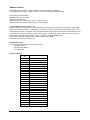
Instrument Setup Record Sheet
Product
Product Code
Serial No
Tag No
Date
Location
Measurement type, range & engineering units
Communication / Baud Rate
LCA15F
VALUE
Inp
P
t
PASS
SP1
IF1
SP2
IF2
HYS
OA
CALL
CALH
At
dA
OPL
OPH
dP
CP
SdSt or LAb
Ln (for printer)
rS
WARRANTY
All LCAF products from Mantracourt Electronics Ltd., ('Mantracourt') are warranted against defective material and workmanship for a period of
(3) three years from the date of dispatch.
If the 'Mantracourt' product you purchase appears to have a defect in material or workmanship or fails during normal use within the period,
please contact your Distributor, who will assist you in resolving the problem. If it is necessary to return the product to 'Mantracourt' please
include a note stating name, company, address, phone number and a detailed description of the problem. Also, please indicate if it is a
warranty repair.
The sender is responsible for shipping charges, freight insurance and proper packaging to prevent breakage in transit.
'Mantracourt' warranty does not apply to defects resulting from action of the buyer such as mishandling, improper interfacing, operation outside
of design limits, improper repair or unauthorised modification.
No other warranties are expressed or implied. 'Mantracourt' specifically disclaims any implied warranties of merchantability or fitness for a
specific purpose. The remedies outlined above are the buyer’s only remedies. 'Mantracourt' will not be liable for direct, indirect, special,
incidental or consequential damages whether based on the contract, tort or other legal theory.
Any corrective maintenance required after the warranty period should be performed by 'Mantracourt' approved personnel only.
ISO 9001
REGISTERED FIRM
CIn the interests of continued product development, Mantracourt Electronics Limited reserves the right to alter product specifications without prior notice.
DESIGNED & MANUFACTURED IN THE UK
Code No. 517-074
Mantracourt Electronics Limited LCA15F User Manual
Issue 3.2
16.04.13
36