1
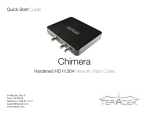
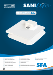
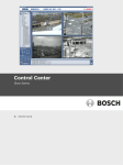
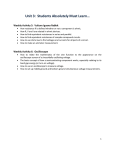
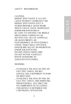
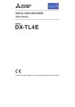
ET Series Digital Video Recorder User’s Manual 1 ET Series User’s Manual 2 ET Series Digital Video Recorder WARNING RISK OF ELECTRIC SHOCK DO NOT OPEN WARNING: TO REDUCE THE RISK OF ELECTRIC SHOCK, DO NOT REMOVE COVER (OR BACK). NO USER-SERVICEABLE PARTS INSIDE. REFER SERVICING TO QUALIFIED SERVICE PERSONNEL. The lightning flash with arrowhead symbol, within an equilateral triangle, is intended to alert the user to the presence of uninsulated “dangerous voltage” within the product’s enclosure that may be of sufficient magnitude to constitute a risk of electric shock. The exclamation point within an equilateral triangle is intended to alert the user to the presence of important operating and Maintenance (servicing) instructions in the literature accompanying the appliance. COMPLIANCE NOTICE OF FCC: THIS EQUIPMENT HAS BEEN TESTED AND FOUND TO COMPLY WITH THE LIMITS FOR A CLASS A DIGITAL DEVICE, PURSUANT TO PART 15 OF THE FCC RULES. THESE LIMITS ARE DESIGNED TO PROVIDE REASONABLE PROTECTION AGAINST HARMFUL INTERFERENCE WHEN THE EQUIPMENT IS OPERATED IN A COMMERCIAL ENVIRONMENT. THIS EQUIPMENT GENERATES, USES, AND CAN RADIATE RADIO FREQUENCY ENERGEY AND IF NOT INSTALLED AND USED IN ACCORDANCE WITH THE INSTRUCTION MANUAL, MAY CAUSE HARMFUL INTERFERENCE TO RADIO COMMUNICATIONS. OPERATION OF THIS EQUIPMENT IN A RESIDENTIAL AREA IS LIKELY TO CAUSE HARMFUL INTERFERENCE, IN WHICH CASE USERS WILL BE REQUIRED TO CORRECT THE INTERFERENCE AT THEIR OWN EXPENSE. CAUTION: CHANGES OR MODIFICATIONS NOT EXPRESSLY APPROVED BY THE PARTY RESPONSIBLE FOR COMPLIANCE COULD VOID THE USER’S AUTHORITY TO OPERATE THE EQUIPMENT. THIS CLASS OF DIGITAL APPARATUS MEETS ALL REQUIREMENTS OF THE CANADIAN INTERFERENCECAUSING EQUIPMENT REGULATIONS. The information in this manual is believed to be accurate as of the date of publication. The information contained herein is subject to change without notice. Revisions or new editions to this publication may be issued to incorporate such changes. 3 ET Series User’s Manual Important Safeguards 1. Read Instructions 13. Damage requiring Service All the safety and operating instructions should be read before the The manufacturer as such additions may result in the risk of fire, Unplug this equipment from the wall outlet and refer servicing to qualified service personnel under the following conditions: A. When the power-supply cord or the plug has been damaged. B. If liquid is spilled, or objects have fallen into the equipment. C. If the equipment has been exposed to rain or water. D. If the equipment does not operate normally by following the operating instructions, adjust only those controls that are covered by the operating instructions as an improper adjustment of other controls may result in damage and will often require extensive work by a qualified technician to restore the equipment to its normal operation. E. If the equipment has been dropped, or the cabinet damaged. F. When the equipment exhibits a distinct change in performance — this indicates a need for service. electric shock or other personal injury. 14. Replacement Parts appliance is operated. 2. Retain Instructions The safety and operating instructions should be retained for future reference. 3. Cleaning Unplug this equipment from the wall outlet before cleaning it. Do not Use liquid aerosol cleaners. Use a damp soft cloth for cleaning. 4. Attachments Never add any attachments and/or equipment without the approval of 5. Water and/or Moisture Do not use this equipment near water or in contact with water. 6. Accessories Do not place this equipment on an unstable cart, stand or table. The When replacement parts are required, be sure the service technician has used replacement parts specified by the manufacturer or that have the same characteristics as the original part. Unauthorized substitutions may result in fire, electric shock or other hazards. 15. Safety Check serious damage to the equipment. Wall or shelf mounting should Upon completion of any service or repairs to this equipment, ask the service technician to perform safety checks to determine that the equipment is in proper operating condition. follow the manufacturer’s instructions, and should use a mounting kit 16. Field Installation approved by the manufacturer. This installation should be made by a qualified service person and should conform to all local codes. equipment may fall, causing serious injury to a child or adult, and 7. Power Sources This equipment should be operated only from the type of power source 17. Correct Batteries Indicated on the marking label. If you are not sure of the type of power, Warning: Risk of explosion if battery is replaced by an incorrect type. Dispose of used batteries according to the instructions. please consult your equipment dealer or local power company. 18. Tmra handling the equipment. A manufacturer’s maximum recommended ambient temperature (Tmra) for the equipment must be specified so that the customer and installer may determine a suitable maximum operating environment for the equipment. 9. Lightning 19. Elevated Operating Ambient Temperature 8. Power Cords Operator or installer must remove power and TNT connections before For added protection for this equipment during a lightning storm, or when it is left unattended and unused for long periods of time, unplug it from the wall outlet and disconnect the antenna or cable system. This will prevent damage to the equipment due to lightning and power-line surges. If installed in a closed or multi-unit rack assembly, the operating ambient temperature of the rack environment may be greater than room ambient. Therefore, consideration should be given to installing the equipment in an environment compatible with the manufacturer’s maximum rated ambient temperature (Tmra). 20. Reduced Air Flow Do not overload wall outlets and extension cords as this can result in Installation of the equipment in the rack should be such that the amount of airflow required for safe operation of the equipment is not compromised. the risk of fire or electric shock. 21. Mechanical Loading 11. Objects and Liquids Mounting of the equipment in the rack should be such that a hazardous condition is not caused by uneven mechanical loading. Never push objects of any kind through openings of this equipment as 22. Circuit Overloading They may touch dangerous voltage points or short out parts that could 12. Servicing Consideration should be given to connection of the equipment to supply circuit and the effect that overloading of circuits might have on over current protection and supply wiring. Appropriate consideration of equipment nameplate ratings should be used when addressing this concern. Do not attempt to service this equipment yourself. Refer all servicing 23. Reliable Earthing (Grounding) to qualified service personnel. Reliable grounding of rack mounted equipment should be maintained. Particular attention should be given to supply connections other than direct conections to the branch circuit (e.g., use of power strips). 10. Overloading Result in a fire or electric shock. Never spill liquid of any kind on the Equipment. 4 ET Series Digital Video Recorder Table of Contents Chapter 1 — Introduction …………………………………………………. 9 1.1 Features ………………………………………………………………………………..9 1.2 Technical Overview …………………………………………………………………10 Chapter 2 – Digital Video Recorder Layout…..………………………. 11 2.1 Front Panel Layout …………………………………..…………………………… 2.2 Front LED Display …………………………………………………………………. 2.3 Rear Panel Layout …………………………………………………………………. 2.4 IR Remote Controller ….………………………………………………………….. 11 14 15 16 Chapter 3 – Installation………………………………………………….. 17 3.1 Connecting the Video Source……………………………………………..………..17 3.2 Connecting the Loop Through Video………………………….…………………..17 3.3 Connecting the Monitor ……………………………………………………..……….17 3.4 Connecting Audio ……………………………………………………………..……...18 3.5 Connecting Alarms ……………………………………………………………..…….18 3.6 Connecting to the RS485……………………………………………………………....19 3.7 Connecting to the Network Port …………………………………………………...20 3.8 Connecting to the RS232 Port ……………….……………………………….…….20 3.9 Connecting to the USB Port …………….…...…………………………………….20 3.10 Connecting to the PTZ Camera Unit ……………..……………………………….21 Chapter 4 — Quick Guide……………………………………………………22 4.1 How to Install ………………………………………………………………………..22 4.2 Common User Interface ……………………………………………………………..22 4.3 Monitoring …………………………………………………………….……………...24 4.4 How to Record …………………………………………..……………..……………..24 4.5 How to Play …………………………………………………………………………….24 4.6 How to setup Networking ………………….………………………..…………..…..24 Chapter 5 — Operation ……………………………………………………..25 5.1 Login to DVR …………………………………………………..………………..…….25 5.2 Logout DVR …………………………………………………….……………..……….25 5.3 Live Monitoring ……………………………………………………………………….26 5.4 Live Cameo Menu …………………………………………………………………….27 5.5 Playback Cameo Menu …………………………………………………………….28 5.6 PTZ Control…………………………….………………………………………..…….31 5.7 Recording Video & Audio ………………………………………………….……….35 5 ET Series User’s Manual 5.8 Searching Video …………………………………….………..…………………….36 Quick Search ………………………………………………………………………….36 Event Search …………………………………………………………………………...37 Overlapped List …………………………………………………….………………….. 37 5.9 Playing Video …………………………………………………………….………….38 5.10 Copying Video Clip………………………………………………..……………….42 5.11 Backup Video Data ……………………………………………………………….43 5.12 Checking DVR Status …………………………………………………………….44 Chapter 6 — Advanced Settings…………………………………………..45 6.1 Camera Setting ……………………………………………………..………………46 6.2 Record Setting……………………………………………………………..………….49 6.3 Networks Setting ……………………………………………………………………51 6.4 System Setting ………………………………………………………………………52 6.5 System Information …………………………………………………………..…….56 Appendix A - Reviewing Backup (Clip) Images ……………………………………....…... 58 Appendix B – How to use the Virtual Keyboard ……………………………………………59 Appendix C – Using Hot Keys ………………………………………………………………..60 Smart Playback ……………………………………………………………………………...60 Panorama Playback ………………………………………………………………………...60 Audio Playback ………………………………………………………………………………60 Cut & Save …………………………………………………………………………………...60 Go to Time Search ……………………………………………………………………...…. 60 Appendix D – Troubleshooting ……………………………………………………………… 61 Appendix E – Specifications ………………………………………………………………… 62 Appendix F – DVR FAQ………………………………………………..………………………63 6 ET Series User’s Manual List of Illustrations Figure 1 — Typical DVR installation ………………………………………………………… 9 Figure 2 — 16-Channel DVR front panel. (Others are similar.) …………………………...11 Figure 3 — Video Input connectors ………………………………………………………….17 Figure 4 — Video Loop Through connectors ……………………………………………….17 Figure 5 — Video Out connectors …………………………………………………………...17 Figure 6 — Audio In and Out connectors ………………………………………….............18 Figure 7 — Alarm Input connector strips ……………………………………………………18 Figure 8 — Alarm Output connector strips ………………………………………………….19 Figure 9 — RS485 Connector ………………………………………………………………..19 Figure 10 — Network connector ……………………………………………………………..20 Figure 11 — RS232 connector ……………………………………………………………….20 Figure 12 — USB connector …………………………………………………………………20 Figure 13 — 8-Channel DVR rear panel. (Others are similar.) ……………….……………21 Figure 14 — ADMIN PASSWORD ………………………………………………………….25 Figure 15 — LIVE CAMEO MENU .……………………………………………….…………..27 Figure 16 — Cameo Menu – Record Change ………………………………….………….27 Figure 17 — Cameo Menu – SEQUENCE ……….…………………………….………….27 Figure 18 — PLAYBACK CAMEO MENU .………………………………………….……28 Figure 19 — CAMERA CHANGE SLIDE ………………………………………………….……....28 Figure 20 — PTZ Mode View …………………………………………………..……………..30 Figure 21 — PTZ MENU …………………………………………………………………..………31 Figure 22 — PTZ -PATTERN .………………………………………………………..………....32 Figure 23 — SEARCH MENU .……………………………………………………….………....35 Figure 24 — QUICK SEARCH 1…………….………………………………….…………….35 Figure 25 — QUICK SEARCH 2…………….………………………………….…………….35 Figure 26 — EVENT SEARCH ……………..………………………….…………………....36 Figure 27 — SEARCH RESULT …………………………………………….……………….36 Figure 28 — OVERLAPPED LIST ………………………………………….……………….36 Figure 29 — Backup …………………...……………………………………….…………….42 Figure 30 — Admin Password ……………………………………………………………….43 Figure 31 — SYSTEM SETUP ………………………………………………………………44 Figure 32 — VGA ADJUSTMENT ……………………………………………………………45 Figure 33 — CAMERA SETUP …………..…………………………………………………47 Figure 34 — PTZ SETUP……………………………………………………………………….48 Figure 35 — ADJUSTMENT SETUP ………………………………………………………49 Figure 36 — RECORD SETUP ……………………………………………………………...50 Figure 37 — NETWORK SETUP ……………………………………………………………52 7 ET Series Digital Video Recorder Figure 38 — INFORMATION ……………………………………………………………………53 Figure 39 — STATUS ……..……………………………………………………………………53 Figure 40 — SYSTEM LOG …………………………………………………………………….54 Figure 41 — MINI PLAYER …………………………………………………………………….55 Figure 42 — VIRTUAL KEYBOARD ………………………………………………………….56 8 ET Series Digital Video Recorder Chapter 1 — Introduction 1.1 Features Your color digital video recorder (DVR) provides recording capabilities for four or eight camera inputs. It provides exceptional picture quality in both live and playback modes, and offers the following features: • 4 or 8 Composite Input Connectors • Compatible with Color (NTSC or PAL) and B&W (CCIR and EIA-170) Video Sources • Multiple Search Engines (Date/Time, Quick, Event) • Records up to 120 NTSC Frames per Second (100 PAL Frames per Second) • “Loop-Through” Video Connectors • Continuous Recording in Disk Overwrite Mode • Video Archiving via Ultra SCSI Interface • Continues Recording while Archiving, Transmitting to Remote Site and during Playback • Various Recording Modes ( Manual / Schedule / Event) • Audio Recording and Playback • Alarm Connections Include: Input, Output. • Built-in Alarm Buzzer • Live or Recorded Video Access via Ethernet or Modem Figure 1 – Typical DVR installation. 9 ET Series User’s Manual 1.2 Technical Overview Your DVR can replace both a time-lapse VCR and a multiplexer in a security installation. However, it has many features that make it much more powerful and easier to use than even the most advanced VCR. The DVR converts analog NTSC or PAL video to digital images and records them on a hard disk drive. Using a hard disk drive allows you to access recorded video almost instantaneously; there is no need to rewind tape. The technology also allows you to view recorded video while the DVR continues recording video. Digitally recorded video has several advantages over analog video recorded on tape. There is no need to adjust tracking. You can freeze frames, fast forward, fast reverse, slow forward and slow reverse without image streaking or tearing. Digital video can be indexed by time or events, and you can instantly view video after selecting the time or Event. Your DVR can be set up for event or time-lapse recording. You can define times to record, and the schedule can change for day, night, weekend and user defined holidays. The DVR can be set up to alert you when the hard disk drive is full, or it can be set up to record over the oldest video once the disk is full. Your DVR uses a proprietary encryption scheme making it nearly impossible to alter video. You can view video and control your DVR remotely by connecting via modem or Ethernet. There is a SCSI port that can be used to record or archive video to external hard disk drives, and also there is a USB port that can used to back up the clip file video to external hard disk drives or memory sticks. NOTE: This manual covers the 4-, 8-channel digital video recorders. The DVRs are identical except for the number of cameras and alarms that can be connected and the number of cameras that can be displayed. For simplicity, the illustrations and descriptions in this manual refer to the 8-camera model. 10 ET Series Digital Video Recorder Chapter 2 — Digital Video Recorder Layout NOTE: Your DVR should be completely installed before proceeding. Refer to Chapter 3 — Installation. 2.1 Front Panel Layout PTZ FAST REWIND(◀◀) Arrow Buttons CD-RW PLAY FAST FOWARD(▶▶) Log Out USB Ports LED NUMERIC KEYPAD Enter Power Fan Remote Sensor CD-RW Record Network Front Function Button Figure 2 — 8-Channel DVR front panel. (Others are similar.) 11 ET Series User’s Manual The front panel looks and operates much like a VCR combined with a multiplexer. Many of the buttons have multiple functions. The following describes each button and control. Take a few minutes to review the descriptions. You will use these to initially set up your DVR and for daily operations. UP, DOWN, LEFT, RIGHT Arrow Buttons These buttons are used to navigate through menus. They are also used to control Pan and Tilt when in the PTZ mode. The arrow buttons can be used to move the position of the active cameo screen, and also move through screen pages. These buttons also have the following functions. ▲ Button: Time Jump playback by the time slide bar in the Playback mode. Tilt the camera up in the PTZ mode. ▼ Button: Backward playback by the hour and backward frame by frame when pressing this button in the PAUSE mode. Tilt the camera down in the PTZ mode. ◀ Button: Backward playback at regular speed in the Playback mode. Pan the camera left in the PTZ mode. ▶ Button: Forward playback at regular speed in the playback mode. Pan the camera right in the PTZ mode. ENTER Button The (Enter) button selects a highlighted item or completes an entry that you have made. NUMBER Buttons (0 ~ 9, +10) Pressing the individual camera buttons will cause the selected camera to display full screen. They are also used to enter passwords. Use the +10 button to select bigger numbers than 10(For example, +10 + 6 = 16). LOG OUT Button Pressing the LOG OUT button exits the menu screen and you have to enter the password again to enter to the Setup menu. DISPLAY Button Pressing the DISPLAY button toggles between different display formats. REC Button (●) When pressing the INSTANT RECORDING button in the live mode, your DVR will start instant recording and you will be asked to confirm the instant recording. 12 ET Series Digital Video Recorder MENU Button Pressing the MENU button enters the Setup screen. You will need to enter the administrator password to access the Setup. Pressing the button also closes the current menu or setup dialog box. ESC Button Pressing the ESC button exits the menu screens or moves to the upper menu. ROTATE Button / PRESET Button Pressing the ROTATE button displays another screen whenever you press this button manually. Pressing the PRESET button run preset menu in PTZ mode. BACKUP Button / ZOOM Button Pressing the BACKUP button displays the Backup menu. Pressing this button again will exit the Backup menu. This button is also used for the Cut & Save hot key. Refer to the Appendix C. Pressing the ZOOM button run zoom menu in PTZ mode. SEARCH Button / FOCUS Button Pressing the SEARCH button displays the Search menu. Pressing the button again will exit the Search menu. This operation is user password protected. Pressing the FOCUS button run focus menu in PTZ mode. PAUSE Button / IRIS Button Pressing the PAUSE button while in the live mode will freeze all live cameo. Pressing the PAUSE button while in the playback mode will pause the video. Pressing the IRIS button run iris menu in PTZ mode. 13 ET Series User’s Manual RW (Rewind) Button / PTZ Button Pressing the RW button plays video backward at high speed. Pressing the button again toggles the playback speed from ◀◀, ◀◀◀, ◀◀◀◀ and ◀◀◀◀◀ and the screen displays ◀◀, ◀◀◀, ◀◀◀◀ and ◀◀◀◀◀ respectively. Used for zooming out in the PTZ mode. Pressing this button in the Pause mode plays video backward at slow speed. Pressing the button again toggles the playback speed from 1/2, 1/4, 1/8 and 1/16. Pressing this button in live mode opens a Pan/Tilt/Zoom screen which allows you to control properly configured cameras. FF (Fast Forward) Button / PLAY Button Pressing the FF button plays video forward at high speed. Pressing the button again toggles the playback speed from ▶▶, ▶▶▶, ▶▶▶▶ and ▶▶▶▶▶ and the screen displays ◀◀, ◀◀◀, ◀◀◀◀ and ◀◀◀◀◀ respectively. Used for zooming in in the PTZ mode. Pressing this button in the Pause mode plays video forward at slow speed. Pressing the button again toggles the playback speed from 1/2, 1/4, 1/8 and 1/16. Pressing this button in live mode plays last played video. But if it can’t play last played video, it runs ‘Go To Last’. 2.2 Front LED Display POWER LED: The POWER LED lights when the DVR is turned on. FAN LED: The FAN LED lights when the fan speed is slow down. CD-RW LED: The CD-RW LED lights when the CR-RW is being used. REC LED: The REC LED lights when the DVR is recording. NET LED: The NET LED lights when the DVR is connected to Network. 14 ET Series User’s Manual 2.3 Rear Panel Layout ① AC POWER INPUT ② ALARM IN ③ ALARM OUT ④ RS485 ⑤ RS232 ⑥ RJ45 ETHERNET PORT ⑦ VGA MONITOR ⑧ AUDIO INPUT/OUTPUT ⑨ SPOT OUTPUT ⑩ LOOP OUT ( 1 ~ 8) ⑪ CAMERA INPUT (1 ~ 8) ⑫ MAIN MONITOR(COMPOSITE VIDEO OUTPUT) 15 ET Series User’s Manual 2.4 IR Remote Controller Instant Record Number Lock (Logout) Menu Display Display Escape Arrow Enter Fast Forward Fast Rewind PLAY PTZ Freeze Search Backup Pause Preset Zoom Iris Focus 16 ET Series Digital Video Recorder Chapter 3 — Installation 3.1 Connecting the Video Source Video In Figure 3 — Video input connectors. Connect the coaxial cables from the video sources to the BNC Video In connectors. 3.2 Connecting the Loop Through Video Loop Figure 4 — Video Loop Through connectors. If you would like to connect your video source to another device, you can use the Loop BNC connectors. NOTE: The Loop BNC connectors are auto terminated. Do NOT connect a cable to the Loop BNC unless it is connected to another terminated device because it will cause poor quality video. 3.3 Connecting the Monitor Main VGA Spot Figure 5 — Video Out connectors. Connect the monitor to either Main or VGA connector. Connect the spot monitor to the SPOT connector if required. 17 ET Series User’s Manual 3.4 Connecting Audio NOTE: It is the user’s responsibility to determine if local laws and regulations permit recording audio. SPK (Speaker) MIC Figure 6 — Audio In and Out connectors. Your DVR can record audio. Connect the audio source to Audio In. Connect Audio Out to your amplifier. NOTE: The DVR does not have amplified audio output, so you will need a speaker with an amplifier. The audio input can be from an amplified source or directly from a microphone. 3.5 Connecting Alarms Alarm In Figure 7 — Alarm Input connector strips. NOTE: To make connections on the Alarm Connector Strip, press and hold the button and insert the wire in the hole above the button. After releasing the button, tug gently on the wire to make certain it is connected. To disconnect a wire, press and hold the button below the wire and pull out the wire. AI 1 to 8 (Alarm In) You can use external devices to signal the DVR to react to events. Mechanical or electrical switches can be wired to the AI (Alarm In) and GND (Ground) connectors. The threshold voltage is 4.3V and should be stable at least 0.5 seconds to be detected. See Chapter 4 — Configuration for configuring alarm input. 18 ET Series Digital Video Recorder GND (Ground) NOTE: All the connectors marked GND are common. Connect the ground side of the Alarm input and/or alarm output to the GND connector. AO 1 TO 8 (Alarm Out) Alarm Out Figure 8 — Alarm Output connector strips. The DVR can activate external devices such as buzzers or lights. Connect the device to the AO (Alarm Out) and GND (Ground) connectors. See Chapter 4 — Configuration for configuring alarm output. 3.6 Connecting to the RS485 RS485 Port Figure 9 — RS485 Connector. The DVR can be controlled remotely by an external device or control system, such as a control keyboard, using RS485 half-duplex serial communications signals. The RS485 connector can also be used to control PTZ (pan, tilt, zoom) cameras. Connect RX-/TX- and RX+/ TX+ of the control system to the TX-/RX- and TX+/RX+ (respectively) of the DVR. See Chapter 4 — Configuration and the PTZ camera or remote controller manufacture’s manual for configuring the RS485 connection. 19 ET Series User’s Manual 3.7 Connecting to the Network Port NET Figure 10 — Network connector. The DVR can be networked using the 10/100Mb Ethernet connector. Connect a Cat5 cable with an RJ45 jack to the DVR connector. The DVR can be networked with a computer for remote monitoring, searching, configuration and software upgrades. See Chapter 4 — Configuration for configuring the Ethernet connections. 3.8 Connecting to the RS232 Port RS 232 Figure 11 — RS232 connector. An RS232 port is provided to connect an external modem for remote monitoring and configuration. See Chapter 4 — Configuration for configuring the modem. NOTE: The DVR is not supplied with a modem cable, and many modems are not supplied with cables. Make certain you have the correct cable when purchasing the modem. 3.9 Connecting to the USB Port USB Figure 12 — USB connector. A USB port is provided to connect external hard disk drives or USB memory sticks for clip copying video. Position the external hard disk drive close enough to the DVR so that you can make the cable connections, usually less than 6 feet. Use the USB cable provided with the hard disk drive to connect it to the DVR. See Chapter 5 — Operation for information on archiving video to an external USB hard disk drive or USB memory stick. 20 ET Series User’s Manual 3.10 Connecting to the PTZ Camera Unit Make a connection of PTZ unit to RS485 at the rear panel of DVR. (See the figure below) PTZ units currently being supported are Pelco-D/P, NVCC-Z42N, CyberDome(Kalatel), Samung, Samsung Techwin, Sungjin, Dongyang, DRX-500, Fastrax II, Sensormatic, PIH-7600, Eyeview Dome. Figure 13 -- DVR Rear Panel RS-485 Connector (9-Pin D-SUB) RX+ RXTXTX+ PTZ Unit 21 ET Series Digital Video Recorder Chapter 4 — Quick Guide 4.1 How to Install Install a Hard Disk Drive to your DVR after opening the upper case. Connect cameras to the Video In No. 1 ~ 8. Connect a Monitor to the Main or VGA. (If necessary, connect the spot monitor to the Spot). Connect a Network cable to the Ethernet port. Turn on the power sources for cameras, monitor and DVR. Your DVR will be initialized and it will take approximately 60 seconds. As soon as the DVR completes its initialization process, it will begin showing live video on the attached monitor and playing live audio through the attached speaker. The default mode is to display all cameras at once. Pressing any camera button will cause that camera to display full screen. It displays live video and plays live audio until the user enters another mode. NOTE: Refer to the Chapter 2 - Installation for more details. 4.2 Common User Interface Icon Remark This color texts are menu names and just texts. This color texts can be highlighted and you can change the setting values. These are buttons for detail setup with sub-menu. 22 ET Series Digital Video Recorder When do you move main menu or close, this message will be occurred if you have changed setting value. If you highlight the OK and press the button, changed values will be applied. But if you highlight the CANCEL and press the button, changed values will be not applied. Just previous values are remained. 23 ET Series Digital Video Recorder 4.3 Monitoring . Using front key pad : Select the desired split screen using the front Display and Sequence keys. To see the FULL screen, use the front numeric keys. Using mouse: Move the mouse to the bottom of screen then activate Bottom Menu to select the split screen. Move the mouse to the Cameo then click the left mouse button to see the FULL screen. NOTE: Refer to the Chapter 4 – Operation. 4.4 How to Record Press the Instant recording button (●) on the front panel. Your DVR will start recording. To stop recording, press this button again. NOTE: Refer to Configuring Recording Settings in the Chapter 4 - Configuration. 4.5 How to Playback Click the search button of the front panel of DVR to find the date and time of recorded material for playback. User is able to search the video using the variety of playback methods of choice. NOTE: Refer to the Chapter 5 – Operation/Searching Video & Playing Video 4.6 How to set up Networking When using a dynamic IP, turn on the Dynamic IP in the Ethernet Setup menu. When using a static IP, enter the IP information in the Ethernet Setup menu. Install the SMS software to your PC and add the DVR information to the SMS. NOTE: Refer to the Ethernet Setup in the Chapter 4 – Configuration and the included SMS manual. NOTE: You will be asked to confirm the password when pressing the front buttons. The default password is 1111. 24 ET Series Digital Video Recorder Chapter 5 — Operation 5.1 Login to DVR This system classifies user category as ADMIN, SUPERUSER, USER limiting the access to system operation. Each log-in authority level and access level has been summarized as below, and ADMIN level overrides all. Press the MENU button to enter the setup screens. The Admin Password screen appears. Figure 14 — ADMIN PASSWORD. Enter the password by pressing the appropriate combination of Camera number buttons and then the Enter button. The factory default password is 1111. The log-in window appears when the following buttons are pressed. Button ( Function ) Log-in Authority MENU Admin SEARCH Superuser BACKUP Superuser PTZ User 5.2 Logout to DVR To log-out from the system click the LOCK button at front panel to brute force log-out or click the Logout button from Top Most Menu using mouse. The DVR system automatically does log-out after a certain time is elapsed. Menu Timeout that has been set to System Setting is the time for predefined automatic log-out time. Button Function Remarks Lock It locks DVR as Logout stage 25 ET Series Digital Video Recorder 5.3 Live Monitoring NOTE: This chapter assumes your DVR has been installed and configured. If it has not, please refer to Chapters 1 and 2. The DVR’s controls are similar to a VCR. As with a VCR, the main functions are recording and playing back video. However, you have much greater control over recording and playing back video. You can establish recording schedules based on time of day, night and weekend. The DVR allows you to search through the recorded video using much more sophisticated tools than those available with VCRs. Additional DVR features that are not available with VCRs are remote control and viewing, recording video at the same time you are watching previously recorded video, and printing images to a standard printer. The Front Panel Display and controls are described in Chapter 2 — Front Panel Layout. As soon as the DVR completes its initialization process, it will begin showing live video on the attached monitor and playing live audio through the attached speaker. The default mode is to display all cameras at once. Pressing any camera button will cause that camera to display full screen. It displays live video and plays live audio until the user enters another mode. Pressing the DISPLAY button cycles the DVR through the different display formats. Pressing the AUTO button will cause the cameras to display sequentially on the monitor. When in one of the multi-view formats, pressing the AUTO button after selecting a channel by pressing the button and moving a square curser by ▲, ▼, ◀ or ▶button will cause the DVR to display live cameras sequentially (cameo sequence). Selecting another display mode, or pressing the AUTO button again will exit the Sequence mode. Pressing the SEQUENCE button allows the manual rotations whenever pressing this button. When in one of live formats, press the button and a green square cursor will appear. You can move the cursor by using arrow buttons and press the button again to pop up the cameo menu. The following screen will appear. 26 ET Series User’s Manual 5.4 Live Cameo Menu When in one of live formats, press the button and green square cursor will appear. When moving the cursor to the bottom or top, the following pop-up menus will appear. Figure 15 – LIVE CAMEO MENU. LIVE HIDDEN ON/OFF You can hidden ON or OFF the live camera to the selected channel. Press the the LIVE HIDDEN ON or LIVE HIDDEN OFF. button after highlighting RECORD CHANGE When selecting the RECORD CHANGE on the above CAMEO menu, the below menu will be popped up. Figure 16 – CAMEO – RECORD CHANGE. You can change the recording quality, resolution and recording speed to the selected channel in this menu. SEQUENCE When selecting the SEQUENCE on the above CAMEO menu, the below menu will be popped up. Figure 17 – CAMEO – SEQUENCE. - CAMEO SEQUENCE : just selected cameo is rotated with the other channels out of monitor. - GROUP SEQUENCE : all channels in monitor is rotated with the other channels out of monitor. - CANCEL SEQUENCE : stop cameo sequence or group sequence. NOTE: you can set rotate frequency on SYSTEM MENU with PLUS MEMU TYPE 27 ET Series Digital Video Recorder 5.5 Playback Cameo Menu When in one of playback formats, press the button and green square cursor will appear. When moving the cursor to the bottom or top, the following pop-up menus will appear. Figure 18 – PLAYBACK CAMEO MENU. Live and Playback Cameo Change You can select a cameo camera and change the selected cameo viewer with live or playback viewer that you want to watch channel. If you want to change the selected cameo to Live Viewer, highlight the LIVE CAM CHANGE and press the button. If you want to change the selected cameo to Playback Viewer, highlight the LIVE CAM CHANGE and press the button. Then, you can select channel you want to view using below slide menu. Figure 19 – CAMERA CHANGE SLIDE. NOTE: If you change cameos using LIVE CAM CHANGE or PLAY CAM CHANGE, changed cameos are preserved until you change cameos, and at next searching and playing also they are preserved. So, to watch default playback cameos you have to highlight the DEFAULT on the upper slide menu and press the button. 28 ET Series Digital Video Recorder Button (Function) Remarks Pressing the button continuously 1, 4, 7, 9 screen display is equentially changed. It helps to monitor efficiently by selecting the choice of screen split. DISPLAY ROTATE FREEZE Pressing the button allows automatic sequential screen split for 1, 4, 9 etc. For example, press the button with 4 screen displays change into the next 4 different camera input with automatically repeating the sequence. Temporary stopping for the monitoring screen and press again resume the original screen mode. Reset the USB module. Enter Numeric Key (0-9) 10+ Num. Key (10+) 29 Selecting Cameo or displaying Cameo menu Used for selecting the corresponding camera directly Used for entering number greater than 10 ET Series User’s Manual 5.6 PTZ Control The DVR will control cameras with Pan, Tilt and Zoom capabilities. Press the PTZ button to enter the PTZ mode. The Mark ‘P’ is printed on the Cameos PTZ camera is set. And the lowest channel is selected among the PTZ Cameos. NOTE: PTZ camera have to already be set. Refer to 6.1 ‘Setup PTZ Camera’ for setting. NOTE: You have to select channel you want to control PTZ camera using numeric buttons. . Figure 20 – PTZ Mode View. You can control the camera using front panel buttons. Press the Left and Right arrow buttons to pan left and right. Press the Up and Down arrow buttons to tilt the camera up and down. You can change PTZ mode using front panel buttons, PRESET, ZOOM, FOCUS and IRIS. - PRESET : PTZ camera is moved to preset location and you can view the location. - ZOOM : you can zoom in or zoom out PTZ camera. - FOCUS : you can set focus manually. - IRIS : you can iris in or iris out. 30 ET Series Digital Video Recorder You can control the camera using front panel buttons or by setting up presets, tour, P-RUN (Pattern Run) or Group. Press the menu button on the front panel. Then you can see below PTZ menu. Figure 21 – PTZ MENU. If you highlight the MOVE in the above menu and press the button, you can tilt the camera. Press the Left and Right arrow buttons to pan left and right. Press the Up and Down arrow buttons to tilt the camera up and down. If you highlight the ZOOM in the above menu and press the button, you can zoom the camera. Press the Fast Forward and Rewind button to zoom in and out. 31 ET Series Digital Video Recorder If you highlight the FOCUS in the above menu and press the Left and Right arrow buttons. button, you can set focus of camera using But if you highlight the SET beside of AUTO FOCUS in the above menu and press the focus will be set automatically. button, camera You can turn on or turn off the light on the camera by toggling ON and OFF beside LIGHT if there is a light on the camera. You can also turn on or turn off the camera by toggling ON and OFF beside POWER. You can toggle TOUR ON and TOUR OFF. If TOUR state is ON, camera will be moved along the already set PRESET GROUP until TOUR OFF. The PRESET GROUP has to be already set. NOTE: Refer to Chapter 5 – PTZ Control - PRESET You can toggle P-RUN ON and P-RUN OFF. If P-RUN state is ON, camera will be moved along the already set PATTERN until P-RUN OFF. The PATTERN has to be already set. NOTE: Refer to Chapter 5 – PTZ Control - PATTERN NOTE: Tour and P-RUN can’t be turned on at the same time. NOTE: Of course, if your camera does not support some function, when you try that function, it will be not accomplished. P-RUN(PATTERN RUN) Press the PATTERN button to set up the Pattern. Then the below pattern menu will be appeared. Figure 22 – PTZ -PATTERN. First, you have to highlight the START beside the PATTERN and press the button to set pattern. Then the START is toggled to the STOP. You can save pattern until you highlight the STOP beside the PATTERN and press the button. Move, zoom or focus the camera by using front panel buttons as described above. Highlight the STOP beside the PATTERN and press the button again, your DVR will save the movements (Pan/Tilt/Zoo). NOTE: One pattern can be saved to your DVR. 32 ET Series Digital Video Recorder If you highlight the PTZ and press the button, the menu will be changed to the previous PTZ menu. You can use P-RUN (Pattern run). Highlight the PATTERN OFF and press the button to use Pattern Run. Your camera will move automatically along the set pattern until you turn off the PATTERN, highlighting the PATTERN ON and pressing the button. PRESET Your DVR can save 64 presets. Follow the next steps to set up presets. Select the preset number and move the camera by using the front panel buttons and press the ESC button to save the preset location. You can assign presets up to 6 to a preset group and set up the dwell time and speed. Select a preset number, press the Time button and set up the dwell time. When pressing the TIME again, the button will change to Speed. Press the Speed button and then you can set up the moving speed. Press the ADD button. After adding 6 presets or less, press the Save button to save the preset group. To run the preset group, turn on the Tour in the upper menu. Your PTZ camera will tour the assigned preset group. NOTE: The Time is the dwell time on a preset position. NOTE: The pattern recalls all the movements, panning, tilting and zooming. NOTE: The preset recalls the preset location. NOTE: The Group means the preset group. NOTE: The Tour means the preset group tour. Button (Function) PTZ ◀◀ Remarks PTZ 모드로 변경한다. Zoom out / Focus out / IRIS close ▶▶ Zoom in / Focus in / IRIS open Num. Key (0-9) Allows to move to the corresponding number of camera. Menu PTZ 모드 상태에서 PTZ 메뉴를 보여준다. ESC PTZ 모드를 해제하고 LIVE 모드로 돌아간다. Returns to the previous menu Up ▲ Moves camera to upward. Down ▼ Moves camera to downward. Zoom in or focus in Left ◀ Moves camera to left Right ▶ Moves camera to right 33 Zoom in or focus out ET Series User’s Manual 5.7 Recording Video & Audio Recording Video Once you have installed the DVR following the instructions in Chapter 3 – Installation, it is ready to record. Unless you change the setup, the DVR will start recording when you press the REC button on the front keypad.. Although you will be able to record without changing the unit from its original factory settings, you will want to take advantages of the DVR’s many tools. See Chapter 4 – Configuration for detailed descriptions of the recording mode options of the recording mode options. Here is a brief description of some of the settings: Recording Audio If the DVR was set up to record audio. It will record audio when video is recording. NOTE: Make certain you comply with all local federal laws and regulations when recording audio. Recording Cameo Window 01:C1 Ch 1 Cameo Window : Time Recording : Motion Recording : Alarm Recording : Videoloss Recording Button Function Remarks Record Start and stop recording button for the current schedule setting 34 ET Series User’s Manual 5.8 Searching Video You can select the media by changing the device beside TARGET. You can playback the recorded video from HDD (Hard Disk Drive), CD or USB. There are five ways of searching the recorded data on DVR. QUICK SEARCH : Search for the recorded video data by date/time. EVENT SEARCH : Search for the event occurred by search date. OVERLAPPED LIST : Search for the data with overlapped date. GO TO LAST : Search for the data which are recorded 10 minute ago from the current time. GO TO FIRST : Search for the data which are recorded at the earliest time among data in the Target device. GO TO JUMP : It is possible to jump by hour or minute. this menu just present on playing recorded video. Figure 23 – SEARCH MENU. QUICK SEARCH Figure 24 – QUICK SEARCH 1. Figure 25 – QUICK SEARCH 2. Days with recorded video listed. You can highlight number of the day with recorded video and press the button to select it. A time bar will be displayed on the TIME SEARCH screen. Hours in which video was recorded will be highlighted with blue. You can use Left and Right arrow buttons to highlight the time bar. Once the time bar is highlighted, you can select time by using the Left and Right arrow buttons. After selecting hour, you can select the time by the three minutes by pressing the button. To play the recorded video, highlight the PLAY and press the 35 button. ET Series Digital Video Recorder EVENT SEARCH Select the EVENT SEARCH in the SEARCH menu. Figure 26 – EVENT SEARCH. Figure 27 – SEARCH RESULT. The EVENT SEARCH screen will display changeable Date/Time, recorded information and channel selection. You can change the date/time and select the channels that you want to search. You can search the recorded video by Motion, Alarm In and Video Loss by turning on or off. Once have selected the events and channels for searching, highlight the SEARCH and press the button. You will be having a recorded list with events and you can playback by selecting one of them on the list. OVERAPPED LIST You can have an overlapped list by selecting OVERAPPED LIST in the SEARCH menu. You can select one of the video files in the list and playback. Your DVR will create the overlapped video list caused by Date/Time changes or applying the DST (Daylight Saving Time). Figure 28 – OVERLAPPED LIST. Button Function Remark Search The very first button to use for search. Pressing the button displays the event search window on screen to search by Year/Month/Day. Enter During the playback, it change the playback mode from Timeline to Hour or Minute 36 ET Series User’s Manual GO TO JUMP It is the function allows to jump into the desired time frame. It is possible to jump by hour or minute. It is possible to perform the function on playing recorded video without PAUSE or STEP PLAYBACK. 5.9 Playing Video Normal Playback It means a normal playback. It supports forward/backward playback as well as playback speed and pause. Single Step Playback Single step playbacks the screen display one frame at a time by pressing up/down button during the pause stage. If you press the button again, it returns to Normal Playback mode. Single Step playback is useful for the viewing of specific video image in details. Smart Playback Pressing the Status button from Normal Playback mode, Smart Playback is activated. Smart playback is a function that allows to display Alarm In section after searching the video that has movement. Forward/Backward playback is possible and pressing Status button during the playback changes to Normal Playback mode. Pressing Status button once again will resume the Smart Playback mode. It is convenient to search and playback the incident that occurred over a given single day. Panorama Playback Pressing up direction key from a single screen playback mode changes to 4/9/16 screen panorama viewing mode. When it goes to single screen, the mode is changed to Normal Playback. Panorama playback does display a single frame of the video into several screen frame by frame. It is very useful feature to monitor a specific video image being changed into. 37 ET Series User’s Manual Normal Playback Normal playback means a steady speed playback. Pressing PLAY button allows to display the video that has been searched through Searching Video. High-speed Playback ( ◀◀ ▶▶ , ) During the playback, press FAST REWIND or FAST FORWORD button. Low-speed Playback ( ◀◀ + || , || ▶▶ + ) After stopping the playback, press FAST REWIND or FAST FORWORD to have low-speed playback. It supports up to 4 different speeds. Step Playback ( || + ▲ , || + ▼ ) When playback is paused, UP or DOWN button is changed to Step Button. Clicking the Step Button allows to playback one frame at a time. 38 ET Series User’s Manual Smart Playback It is ideal playback for video with many movements. It is useful for fast checking of video clips. ▼ ) in front panel works the same. Pressing the S key ( Panorama Playback During playback select panorama from Cameo Menu, then select number of screens to be displayed. If you press P key ( ▲ ) during the single screen display, panorama is play backed. Up key controls the number of splitting screens. 39 ET Series User’s Manual Button Function Search Remarks The first button to sue for search. Pressing the button displays calendar search and event search window. Escape Cancel the playback and change to live screen mode Enter Select Cameo from playback screen Fast Rewind Playback speed up and down control for backward direction Fast Forward Playback speed up and down control for forward direction || Pause Temporary stopping of playback ▶ Forward Play Forward playback of video data ◀ Reverse Play Backward playback of video data Up Panorama playback mode select key. ◀◀ ▶▶ Use the button to change Cameo into live or playback mode Use the button to change Cameo into live or playback mode Step playback with PAUSE. Down Smart playback mode select key. Step playback with PAUSE. Display 40 Change the split mode of playback screen ET Series Digital Video Recorder 5.10 Copy Video Clip This is the function that allows to copy a part of video clip during play back into USB or other recording media. There are two ways of using it with cameo menu and front keys. Using the front keys on PLAYBACK - Click the BACKUP key for starting time - Section to copy is made, click the BACKUP key again - After that, click the BACKUP key of front keys Make a copy after confirming the user selected channel and time frame. Select CD or USB for storage media from TARGET. • DvrPlayer is copied into backup CD or USB device automatically. • Backup video can be played using DvrPlayer. • ( ※ DvrPlayer : Single channel video player similar to Windows Media Player ) Button Function Remarks Backup Pressing the button displays GUI for data backup to the saving device. Spot Set the beginning/ending video data fro backup during the playback. 41 ET Series Digital Video Recorder 5.11 Backup Video Data BACKUP TO THE INTERNAL CD-RW You can backup the recorded video to the built-in CD-RW. Press the BACKUP button on the front or remote. The following Backup screen will be appeared. 그리고 CHANNEL 옆의 박스를 누르면 오른쪽 그림과 같이 서브 메뉴창이 떠서 채널을 선택할 수 있다. Figure 29 – BACKUP. You can set up the Date/Time for backup and select the channels. Press the ESTIMATE button and your DVR will calculate the data size and display beside the REQUIRED SPACE. Press the WRITE button and your DVR will prepare the burning to a CD and the CD space is limited up to 650MB. NOTE: When the data size is bigger than 650MB, you will be asked to put a new CD after burning the first CD. You will be asked to confirm to backup the data to a CD. • DvrPlayer is copied into backup CD or USB device. • Backup video can be played using DvrPlayer. • ( ※ DvrPlayer : Single channel video player similar to Windows Media Player ) Button Function Remarks Backup Pressing the button displays GUI for data backup to the saving device. 42 ET Series Digital Video Recorder Chapter 6 — Advanced Settings Before using your DVR for the first time, you will need to establish the initial settings. This includes items such as time and date, camera, audio, remote control, record mode, network and password. Your DVR can be set up using various screens and dialog boxes. Press the MENU button to enter the setup screens. The Admin Password screen appears. Figure 30 — ADMIN PASSWORD. Enter the password by pressing the appropriate combination of Camera number buttons and then the Enter button. The factory default password is 1111. 43 ET Series Digital Video Recorder 6.1 System Setting Configuring System Settings SYSTEM SETUP is the General Setup ,video format , date and time format and set VGA adjustment. You can reboot or shutdown system in this menu. Figure 31 — SYSTEM SETUP. Video Format Setup & TV OUT Highlight the input type beside VIDEO FORMAT and press the between NTSC and PAL. button to select input video format You have to select correct video format. You can select Video output mod. When TV OUT is ON, CCTV output is available. Otherwise, Video ouput is gerneral VGA. General Setup You can select the time zone by highlighting the boxes beside and pressing the button. NOTE: When selecting a time zone, the DST (Daylight Saving Time) will be applied in case of using the DST in you region and also your DVR will reboot the system automatically. NOTE: When selecting the DST OFF, the DST (Daylight Saving Time) will not be applied. You can turn on or off OSD (On Screen Display) for the date and time on the screen by highlighting the box beside DATE/TIME and pressing the button. NOTE: When turning off the DATE/TIME display, your DVR will not display the date and time information on the screen. You can set DATE or TIME when DATE or TIME menu is selected, using buttons. If you press the button, value will be increased and If you press the button, value will be decreased. If you press the button, cursor will be moved to left value and If you press the button, cursor will be moved to right value. 44 ET Series User’s Manual VGA Adjustment Figure 32 — VGA ADJUSTMENT. Highlight VGA ADJUSTMENT and press the button. The VGA ADJUSTMENT screen appears. The ADJUSTMENT screen displays the brightness, contrast, saturation. Highlight values beside BRIGHT, CONTRAST or SATURATEION and press the button. Then Slide window pop up. You can set value and SAVE. NOTE: Highlight the SAVE button and press the button to save your changes in the sub-menu. Menu Style change If you want to set or change the detail and advanced menu, you have to change menu style to PLUS from BASIC. Default menu style is PLUS. Highlight the value beside MENU STYLE and press the button. When you change the MENU STYLE to PLUS, DVR will ask you to input ADMIN password with below confirm menu. NOTE: You can set up DVR in detail using PLUS MENU. But Using PLUS MENU is more difficult because there is much menu and you have to know detail information about DVR. 45 ET Series User’s Manual Load Default Setup You can load FACTORIAL DEFAULT to the DVR system. Highlight LOAD beside FACTORY DEFAULT and press the button. Then, you can select loaded menus by checking menus you want. Menus checked with O mark are loaded and with X mark are not loaded. NOTE: Your DVR will be initialized to the factory default when loading the FACTORY DEFAULT. Shutdown You can shutdown your DVR by highlight the SHUTDOWN in the SYSTEM menu and pressing the button. When you highlight the SHUTDOWN and press the button, You have to input the Admin Password to confirm identification. After then, Your DVR will ask you really want to turn off DVR system. If you highlight OK and press the button, DVR system will be downed. NOTE: To turn off the DVR, you have to power down after SHUTDOWN. The DVR power switch is at the back of the DVR. 46 ET Series Digital Video Recorder 6.2 Camera Setting Configuring Camera Settings This is the menu for general camera setting, camera image color or location control, or setting for PTZ camera Figure 33 — CAMERA SETUP. Camera label display change You can select CAMERA LABEL among ALL, NAME, NUMBER or OFF. Camera name assign You can assign names to each camera by highlighting the boxes below NAME. A virtual keyboard allows you to enter camera names. NOTE: Refer to Appendix B – How to use the virtual keyboard. 47 ET Series Digital Video Recorder Setup PTZ camera Figure 34 — PTZ SETUP. You can set up each PTZ camera by highlighting the boxes below PTZ and press the button. You can set up the baud rate, data bit, parity and stop bit by highlighting the boxes below PORT and press the button. You can set up IDs for each channel on the ID heading by highlighting the boxes below ID and press the button. You can set up PTZ camera type by highlighting the boxes below TYPE and press the Select your camera from the list and press the button. button You will need to connect the camera to the RS485 terminal on the back of the DVR following the camera manufacturer’s instructions. 48 ET Series User’s Manual ADJustment Setup Screen Figure 35 — ADJUSTMENT SETUP. Highlight ADJ and press the button. The ADJUSTMENT screen for all channel appears. Highlight below ADJ in the main menu and press the channel appears. button. The ADJUSTMENT screen for each The ADJUSTMENT screen displays the brightness, contrast, saturation, hue and position. You can select the channel by highlighting the box right CAMERA and pressing the button. You can select the live or recorded video by highlighting the box beside SCREEN MODE and pressing the button. You can adjust the brightness, contrast, saturation and hue by highlighting the headings. You can change the position of the screen by highlighting the arrow buttons of the POSITION and pressing the button. You can apply your adjustments to all the channels by using the APPLY ALL button. NOTE: Highlight the SAVE button and press the 49 button to save your changes in the sub-menu. ET Series User’s Manual 6.3 Record Setting Configuring Recording Settings Your DVR offers a variety of flexible recording modes. You can set it up to record all the time or to only record events. Figure 36 — RECORD SETUP. Video Recoding Setup Highlight RESOLUTION and press the resolution. Highlight QUALITY and press the HIGHEST and SUPER. button. You can select either STD(CIF) or HIGH(HVGA) button. You can select the recording quality among STD, HIGH, The TIME RECORD can be set for Day, Night and Weekend. Highlight the TIME RECORD and press the button to select TIME RECORD time, (ALL, DAY ONLY, NIGHT ONLY, WEEKEND, DAY/NIGHT, DAY/WEEKEND, NIGHT/WEEKEND, OFF). When it is selected time, DVR will record. And time record SPEED also can be set. Highlight the value beside of SPEED(FPS) and press the button to set TIME RECORD SPEED. You can set up EVENT RECORD time for Day, Night and Weekend. Highlight the EVENT RECORD and press the button to select EVENT RECORD time, (ALL, DAY ONLY, NIGHT ONLY, WEEKEND, DAY/NIGHT, DAY/WEEKEND, NIGHT/WEEKEND, OFF). When it is selected time, DVR will record if events are occured. And event record SPEED also can be set. Highlight the SPEED(FPS) below the EVENT RECORD and press the button to set EVENT RECORD SPEED. NOTE: Upper settings are applied to all channels. 50 ET Series User’s Manual Audio Recoding Setup The AUDIO RECORD can be set for Day, Night and Weekend. Highlight the AUDIO RECORD and press the button to select AUDIO RECORD time, (ALL, DAY ONLY, NIGHT ONLY, WEEKEND, DAY/NIGHT, DAY/WEEKEND, NIGHT/WEEKEND, OFF). When it is selected time, Audio will be recorded. Recording Message Setup You can set up whether messages are displayed or not. EVENT MESSAGE is appeared when set EVENT is occurred. RECORD MESSAGE is appeared when DVR is recording. RECORD MARK is appeared when DVR is recording. Highlight the EVENT MESSAGE , RECORD MESSAGE or RECORD MARK and press the toggle ON and OFF to use each message. button to NOTE: Under-side table refers to three event message , four recording message and one recording mark. Motion event message Video loss event message Alarm event message Motion recording message Video loss recording message Alarm recording message Time recording message Recording mark 51 ET Series User’s Manual 6.4 Network Setting Configuring Network Settings Control communication related setting from DVR. It is set for commonly using Ethernet and connecting from client. Figure 37 — NETWORK SETUP. Ethernet Setup You can turn on or off the dynamic IP by highlighting the box beside the DYNAMIC IP and pressing the button. When turning off the Dynamic IP, you can enter the static IP information. Enter the DVR name to the box beside HOST NAME and enter the domain name to the box beside DOMAIN NAME by highlighting the boxes beside and pressing the button. The virtual keyboard will appear for typing. NOTE: Refer to Appendix B – How to use the virtual keyboard. You can enter IP ADDRESS, SUBNET MASK, GATEWAY and DNS, using Numeric buttons. buttons or If you press the button, value will be increased and If you press the button, value will be decreased. If you press the button, cursor will be moved to left value and If you press the button, cursor will be moved to right value. SMS Port Setup Enter the TCP Port for SMS client connection. The default TCP port is 7000. WEB Port Setup Enter the TCP Port for WEB client connection. The default TCP port is 80. 52 ET Series User’s Manual 6.5 System Information Checking System Information You can view the information of system, SYSTEM LOG, VERSION and KEY INFO. Figure 38 — INFORMATION Checking Status You can check the status of the DVR by pressing the STATUS button. The Status screen displays Recording, Event and Audio status and Disk and Key information. Figure 39 – STATUS. 53 ET Series User’s Manual View Version You can check the version of your DVR in the VERSION menu. Refer to the below screen. The VERSION screen will display the version information. View System Log You can check the system log by selecting the SYSTEM LOG in the main menu. The below screen will appear. You can move to the previous page or next pages by pressing PREV or NEXT button in the SYSTEM LOG menu. 54 ET Series Digital Video Recorder Appendix A – Reviewing Backup (Clip) Images Save Print Full Screen Mode Show Play List Backward frame by frame Open video file Forward frame by frame Figure 41 – MINI PLAYER. Your DVR will download the Mini Player with the backup files. You can play the backup files with the Mini Player on your PC and convert the files to .JPG or .AVI format. 55 ET Series User’s Manual Appendix B – How to use the virtual keyboard Figure 42 — VIRTUAL KEYBOARD You will be using the virtual keyboard when setting up the DVR. Highlight the button and press the button to enter. The SHIFT button switch the capital letters and the small letters. Exactly, upper two figures of virtual keyboard will be toggled when you highlight the SHIFT and press the button. the BACK button has a cursor be moved left and one last character be deleted. The CLEAR button clean all input characters in the text box. If you want to use input words and exit, highlight the OK and press the button. If you don’t want to use input words and exit, highlight the CANCEL and press the 56 button. ET Series Digital Video Recorder Appendix C – Using Hot Keys Smart Playback: Press the DOWN arrow button when playing back video. In the Smart Playback mode, your DVR will play back the recorded video that has motions. Panorama Playback: Press the UP arrow button in a single channel playback. NOTE: The Panorama playback is working in single channel screens only. You can change the screen to 2x2, 3x3, 4x4 formats by pressing the Up arrow button in the Panorama mode. Cut & Save: BACKUP Æ BACKUP Æ BACKUP. You can set up the start time by pressing the Spot button first time and set up the end time by pressing the Spot button again. Press the Backup button after setting up the start and end time. 57 ET Series User’s Manual Appendix D - Troubleshooting Problem Possible Solution No Power • Check power cord connections. • Confirm that there is power at the outlet. No Live Video • Check camera video cable and connections. • Check monitor video cable and connections. • Confirm that the camera has power. • Check camera lens settings. Live Video Very Bright If a cable is attached to the “Loop” connector, make certain it is connected to a properly terminated device. Mouse is not working Press the FREEZE to reset the mouse. DVR has stopped recording If hard disk is full, you will either need to delete video or set the DVR to the Overwrite Mode. 58 ET Series Digital Video Recorder Appendix E – Specifications ET 800 Inputs i4 CH Composite videos Outputs iCCTV Monitor(NTSC/PAL), iCRT(VGA) Monitor (Option) i1 Spot CCTV Monitor(NTSC/PAL) Display iNTSC : 120fps Screen split i1/4 Split Performance iNTSC CIF(120fps),HVGA(60fps), VGA(30fps) iPAL CIF(100fps),HVGA(50fps), VGA(25fps) Resolution iNTSC : CIF(336x224), HVGA(672x224), VGA(672x448) iPAL : CIF(336x272), HVGA(672x272), VGA(672x544) Video Monitoring Recording 400 iPAL : 100fps i8 CH Composite videos iNTSC : 240fps iPAL : 200fps i1/4/8 Split iNTSC CIF(120fps), HVGA(60fps), VGA(30fps) iPAL CIF(100fps), HVGA(50fps), VGA(25fps) Compression i Algorithm tuned for DVR applications from JPEG, H.263 and MPEG standard Mode iMotion detection, Sensor, Schedule iVariable compression rate, recording frame, motion sensitivity Storage media i Internal Max. 4 x HDD (Option) Audio i1 Channel, G.726 Compression Mode i Multi-channel playback(Max 4, 8 ch), Simultaneous playback, Panorama playback Searching iBy Channel, Time, Date, Motion detection, Sensor events Playback Remote Monitoring S/W Alarm/Sensor Camera Control Back-up iRemoval CD R/W or HDD (Option) iServer Management Software (SMS) i1/4 i1/8 iPan/Tilt, Zoom, Focus, Iris iThrough External USB2.0 Ports(Memory Stick, HDD, CD R/W) iRemoval HDD, CD-RW/DVD RW iRemote S/W Size / Weight i350(W) x 400(D) x 88(H) : 2U Rack Mount Kit / i6 kg Hardware Spec. Power iMax. 50W, 90~264(47Hz~63Hz) UPS iExternal UPS (Option) 59 ET Series Digital Video Recorder Appendix F – DVR FAQ General Q. What does Embedded Linux mean? A. Embedded Linux means that the operating system of the DVR has been implanted onto the CPU (Central Processing Unit). This means that the system response time is faster, is more stable, and that the core of the DVR is never affected by external factors, such as virus, hacking, and system failure due to hard drive abnormalities. Q. Is the DVR up-gradable by CD or network ? A. Both are possible by CD-RW and client program. Q. How can I reset DVR to the factory default setting? A. Load the factory default setting from CONFIG menu. Live Monitoring Q. Is it possible Live screen monitoring with specific cameras? A You can set the camera sequence through CAMEO swap. Recording Q. How do you record? A. Using the Time Record와 Event Record from RECORD menu, or Default Record button allows to record. Q. What is Time Recording? A. It is recording that is not related to event recording. Q. What does that Event mean? A. That means Motion, Alarm In, Video-loss event activity. Q. What is Event Recording? A. It only records when the event occurs and that triggers the recording. Searching & Playing Video Q. How to playback the video? A. Search time and event to playback from Search menu. Q. Is it possible to view Live screen during the playback? A. It is possible to see using Live Cam Change from CAMEO Menu during the playback. Q. Is it possible to copy the wanted section of video during the playback? A. Yes, select starting and ending time with Spot key, then using the Backup key to save. Backup Q. Is it possible to backup to DVD media? A. DVD-RW device is installed then it is possible. Q. Can USB memory stick be used? A. Yes. 60 ET Series Digital Video Recorder Network Q. A. Q. A. Does it support dynamic IP? Set the Dynamic IP from Ethernet Setup allows to use it. Mail is not sent out. All the setting in Ethernet Setup value should be set correctly. Miscellaneous Q. Is it possible to use either mouse, joystick or keyboard through the USB port? A. Mouse input device and memory stick is supported as the primary device. Q. What type of cameras should be used? A. NTSC or PAL system cameras are OK to use. 61 ET Series 62 ET Series User’s Manual Menu Style change If you want to set or change the detail and advanced menu, you have to change menu style to PLUS from BASIC. Default menu style is BASIC. First, press the MENU button on front keypad. Then, select system menu in main menu. There is MENU STYLE and you can change it. Highlight the value beside MENU STYLE and press the button. When you change the MENU STYLE to PLUS, DVR will ask you to input ADMIN password with below confirm menu. NOTE: You can set up DVR in detail using PLUS MENU. But Using PLUS MENU is more difficult because there is much menu and you have to know detail information about DVR. To change again to BASIC menu style from PLUS menu style, move the SYSTEM menu. Then, change MENU STYLE to BASIC. 63 ET Series