1
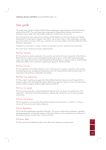
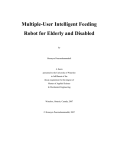
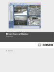
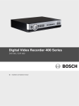
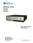
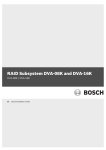
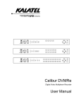
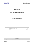
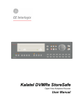
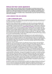
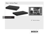
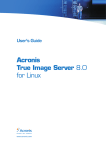
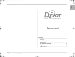
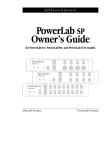
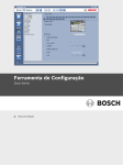
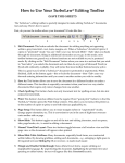
Control Center
Divar Series
en
Operation manual
Control Center
Table of Contents | en
3
Table of Contents
1
Introduction
5
1.1
Getting started
5
1.2
System requirements
5
1.2.1
Software installation
5
1.2.2
Firmware upgrades
6
1.2.3
Conventions used in the application
6
2
Live operation
7
2.1
How to Log on
7
2.2
Live video window
8
2.3
Top button bar
9
2.3.1
Live button for multiple Divar units
9
2.3.2
Playback button for single Divar
9
2.3.3
Camera views
9
2.3.4
Capturing a still image
10
2.3.5
Instant playback
10
2.3.6
Audio
10
2.3.7
Config button
10
2.3.8
Monitor stream mode
10
2.3.9
Help button
11
2.3.10
Log off button
11
2.4
Selecting Divar units, cameras, groups, and views
11
2.4.1
Context menu
12
2.4.2
Drop-down menu
12
2.4.3
System Management icons
12
2.4.4
Managing groups
12
2.4.5
Making views
13
2.5
Checking alarms and motion events
13
2.6
Checking status information
14
2.7
Assigning cameras to cameos
14
2.7.1
Cameo icons
15
2.8
Controlling cameras
15
2.9
Activating output relays
16
3
Playback operation
17
3.1
Playback window
17
3.2
Top button bar
18
3.2.1
Selecting single or multiscreen views
18
3.2.2
Text unit
18
3.2.3
Capturing a still image
18
3.2.4
Selecting viewing window size
18
3.2.5
Audio
18
3.3
Selecting a camera
19
3.4
Using the playback controls
19
3.5
Overview tab
20
3.5.1
Earliest and latest recording times
20
Bosch Security Systems
Operation manual
AR18-09-B014 | v3.0 | 2009.11
4
en | Table of Contents
Control Center
3.5.2
Date and time of selected image area
20
3.5.3
Time line scale
20
3.5.4
Time line display
20
3.5.5
Date/time axis
20
3.5.6
Selecting recordings
21
3.5.7
Disk Space usage (Divar Classic only)
21
3.6
Search tab
21
3.6.1
Oldest and newest recording times
21
3.6.2
Setting the search period
22
3.6.3
Go to function
22
3.6.4
Camera selection
22
3.6.5
Event filter
22
3.6.6
Start search
22
3.6.7
Search results
22
3.7
Smart Motion tab
23
3.7.1
Oldest and newest recording times
23
3.7.2
Setting the search period
23
3.7.3
Go to function
23
3.7.4
Camera selection
23
3.7.5
Search direction
24
3.7.6
Sensitivity
24
3.7.7
Smart Motion tab
24
3.7.8
Show grid
24
3.7.9
Start search
24
3.7.10
Search results
24
3.8
Text tab
25
3.8.1
Oldest and newest recording times
25
3.8.2
Setting the search period
25
3.8.3
Go to function
25
3.8.4
Camera selection
25
3.8.5
Free text data search
26
3.8.6
Case sensitive search
26
3.8.7
Search results
26
3.9
Protected tab (Divar Classic only)
26
3.9.1
Oldest and newest recording times
26
3.9.2
Disk space used
27
3.9.3
Setting the search period
27
3.9.4
Searching for protected recordings
27
3.9.5
Search results
27
3.10
Handling recordings
27
3.10.1
Checking authenticity
27
3.10.2
Exporting recordings to a PC hard disk
28
3.10.3
Deleting recordings
28
3.10.4
Protecting recordings (Divar Classic only)
28
3.10.5
Unprotecting recordings (Divar Classic only)
28
AR18-09-B014 | v3.0 | 2009.11
Operation manual
Bosch Security Systems
Control Center
Introduction | en
1
Introduction
1.1
Getting started
5
The Divar Control Center gives full remote control via a PC of the Divar 700 Series, Divar XF
and Divar Classic DVRs. Any Divar connected to the network can be controlled and multipleuser access is available for up to eight users (five simultaneously). Multiple Divar units can be
controlled simultaneously.
Remote live viewing, search, playback, and system configuration are provided (if permissions
have been granted). Remote control functions include pan, tilt, and zoom control of cameras
(including full AutoDome control), and video archiving. An on-line status overview of the
connected units is also provided.
Access to the Configuration Tool to set up a Divar is limited and can be password protected.
The functions available to each remote user can also be restricted, for example, the ability to
archive video. See the relevant Divar user manual for more information.
Search and playback functions can be blocked, so it is possible they are not directly available.
All possible operator facilities are described in this manual but some of these may not be
available to every user or on every model or unit.
The Archive Player is provided so that archived video recordings can be viewed on any
reasonably current Windows PC without requiring additional installation. All recordings have
an authentication code embedded in them. This makes it possible to check their authenticity
to ensure that they have not been tampered with.
1.2
System requirements
Operating platform: A PC running Windows XP or Windows Vista.
For the Control Center and Archive Player, the recommended PC requirements are:
–
Processor: Intel Pentium DualCore, 3.0 GHz or comparable
–
RAM memory: 2048 MB
–
Free hard disk space: 10 GB
–
Graphics card: NVIDIA GeForce 8600 or higher
–
Video memory: 256 MB
–
Network interface: 10/100-BaseT
Note:
For each camera that is viewed on Control Center, 9 MB of video memory is reserved. If there
is insufficient video memory to display a multiscreen view, a warning message is shown and
the multiscreen is not displayed.
1.2.1
Software installation
1.
Insert the CD-ROM into the CD-ROM drive of the PC;
–
2.
The installation program should start automatically.
If installation does not start automatically, locate the Setup.exe file on the CD and
double-click it.
3.
Follow the instructions on the screen to complete the installation.
Starting the program
When installation is complete, double-click the Divar Control Center icon on the desktop
window to start the program. Alternatively, select the Divar Control Center program via the
Bosch Security Systems
Operation manual
AR18-09-B014 | v3.0 | 2009.11
6
en | Introduction
Control Center
Start button on the task bar and the Programs menu.
1.2.2
Firmware upgrades
Firmware upgrades are released periodically. Check the Bosch Security website for the latest
version.
Note:
Whenever the Control Center application is upgraded to a newer software version, any saved
configuration backup file exported from the older version of the software will no longer be
useable with the new software. During the upgrade process, the existing configuration of the
Control Center will be adapted to the new version of the software. Re-export the
configuration to a new backup file to ensure that a backup configuration file can be restored
using the new software.
1.2.3
Conventions used in the application
Interpreting icon colors
–
Disabled functions are shaded.
–
Active selections are highlighted in yellow or when in pressed state.
Calendar window
The calendar window is displayed after clicking the calendar icon in windows where a date
must be filled in.
–
Click the arrow keys to change months.
–
Click a date to return to the date box with the selected value filled in.
–
Press Esc on the keyboard to leave the window without changing the date.
Lists
–
In lists, click a column header to sort the list according to that column item.
–
Click a second time to sort the list in reverse order.
–
Use the scroll bars to scroll through long lists.
Progress bar
–
A progress bar is displayed when a task is running that takes some time to complete.
–
Click Cancel to stop the task.
Confirmation window
A confirmation window is displayed when an irreversible operation is selected.
–
Click Yes to proceed with the operation.
–
Click Cancel to abandon the operation.
Error window
An error window is displayed whenever an error occurs:
–
Click OK to dismiss the error notification.
Refresh
Update of values and status indications.
Expand/collapse lists
In the System Management window, the tree structure shows a + or a - next to an icon. Click
the + to expand the list; click the - to collapse the list.
AR18-09-B014 | v3.0 | 2009.11
Operation manual
Bosch Security Systems
Control Center
Live operation | en
2
Live operation
2.1
How to Log on
7
When the Control Center application is started for the first time, the user name and password
boxes are blank. The device list is also empty. One or more Divar units must first be added to
the list.
Click Edit to add a Divar to the list.
To modify the Divar list
Add or delete Divar units from the list using the Edit Divar list window. Change the name and
IP address of a selected unit here as well.
To automatically detect all enabled Divar units on the network:
1.
Click Detect;
–
To detect a unit, Discovery must be enabled (in the local user interface) on that unit.
2.
Select the unit(s) to be added.
3.
Click OK to add the selected unit(s) to the list.
To manually add a Divar to the list:
1.
2.
Click Add.
Enter the IP address or DNS name of the new unit;
–
The IP address to be filled in is set in the setup menu of the unit itself. Check with
the administrator for access to the unit, if needed.
3.
Type a name in the Name box or retrieve it from the unit by checking the Retrieve from
Divar box.
4.
Click OK.
To delete a Divar from the list:
1.
2.
Select the unit to be deleted.
Click Delete;
–
The selected unit is removed from the list.
Log on
Start the Control Center application, the Log on window appears. (Click Cancel to
discontinue log on and exit the application.)
Figure 2.1 Log on window showing Divar list
Bosch Security Systems
Operation manual
AR18-09-B014 | v3.0 | 2009.11
8
en | Live operation
Control Center
To log on to a particular Divar:
1.
Select the units to log on to by placing check marks next to them:
–
Click
–
If a login group has been defined, select this group to log on to the units listed in the
to select either all or none of the units listed.
group.
2.
Type user name and password:
–
The user name and password to be filled-in are set in the unit itself. Check with the
–
Place a check mark in the Save log on information box to let the system remember
administrator if access is denied to the unit.
the name and password on subsequent uses of the Control Center. Administrator
passwords are not saved.
3.
2.2
Click Log on.
Live video window
The live video window appears upon log in. This is the main window.
Figure 2.2 Live video window
The main window consists of five areas:
–
A horizontal top button bar, containing buttons for screen control and system settings.
–
A vertical side bar, containing controls for system management, camera control, and relay
control.
–
A video area, showing live video from one or more cameras and Divar units.
–
A status message window, showing live status information from all connected DVRs.
–
Status window button, and alarm and motion icons.
AR18-09-B014 | v3.0 | 2009.11
Operation manual
Bosch Security Systems
Control Center
Live operation | en
The Control Center
9
icon in the top left of the window allows the user to manipulate the
window size, close the application, or select system settings.
To change the system settings:
1.
Click the Control Center
–
icon and select Settings...
The system settings dialog window opens.
2.
Place a check mark next to the items to be activated;
3.
Select a sequence dwell time between 5 and 60 seconds to determine how long a
–
The computer beeps on the specified alarms or maximizes the application window.
sequenced view remains displayed.
4.
Click OK to save changes and close or Cancel to close the window without change.
2.3
Top button bar
2.3.1
Live button for multiple Divar units
The live video window is shown by clicking Live
2.3.2
. On this screen the user can:
–
view live video
–
select different multiscreen displays
–
assign cameras to cameos
–
open an instant playback window of the active cameo
–
take a snapshot of the active cameo
–
control cameras
–
monitor unit status and alarm conditions
–
log in to other units on the network
–
set up logical groups and views
Playback button for single Divar
Click Playback
to show the playback window. Get a graphical timeline overview of all
recordings, or search for recordings based on events and play them back.
2.3.3
Camera views
To switch the display mode, click one of the camera view
icons to change the
cameo display configuration:
–
Single, Quad, 3x3, and 4x4 multi-image display modes are available.
To select the sequence mode, click the sequence
icon to start sequencing through a list of
cameras:
–
If a group is selected in the System Management window, the Control Center sequences
through all direct members of that group (including subgroups).
–
If a view or camera is selected in the System Management window, the Control Center
–
If a Divar is selected in the System Management window, the Control Center sequences
–
The Control Center uses the dwell time set in the Control Center system settings.
selects that item and sequencing is not possible.
through all cameras on that unit in single mode.
To select multiple items, extend the selection by holding down the ctrl key while selecting
additional items.
Multiscreen views
Dependent on the number of supported video inputs, multiple multiscreen views are
available. The current view is indicated by a number in the multiscreen
icon.
Each multiscreen view can have unique camera-to-cameo assignments:
Bosch Security Systems
Operation manual
AR18-09-B014 | v3.0 | 2009.11
10
en | Live operation
Control Center
–
2.3.4
To manually cycle through the available views, click the multiscreen
icon.
Capturing a still image
Capture still images from the fullscreen display of a camera and save them to the PC hard disk
in a bitmap format.
To save an image from the active cameo to the PC hard disk:
1.
Click the single
2.
Click the snapshot
–
icon to view the images from one camera.
icon;
The Snapshot pop-up page appears.
3.
To change the default location, type the path in the PC file system to store the image file.
4.
To change the file name, type the new name for the file.
5.
Click Save.
The snapshot has the same resolution as the video image (CIF, 2CIF, or 4CIF, depending on
the recording settings). Authentication information is shown under the image.
2.3.5
Instant playback
To view the recorded video of a particular camera from one minute earlier:
1.
2.
Click the cameo of the camera that contains the video to make it active.
Click the Instant Playback
icon;
–
A new window opens which plays back the recorded video of this camera from one
–
Use the buttons at the bottom of the instant playback window to control playback or
minute earlier.
take a snapshot.
–
Click the close button at the top right corner of the instant playback window to
close it.
An alternative method of opening the instant playback window is to right click a camera in the
System Management window and select Instant Playback.
2.3.6
Audio
Click audio
to enable or disable audio streaming or adjust the volume. When enabled, the
audio of the selected cameo will be heard, if available.
2.3.7
Config button
Click Config
to start the configuration tool program. This allows set up of all the
configuration settings for supported devices. A log on dialog box is opened with known
devices for which a configuration tool is installed. An alternative method of starting the
Configuration Tool is to right-click a DVR in the System management window and select
Configure. Configuration rights are needed to access this program.
2.3.8
Monitor stream mode
Click
to enable direct DVR control while viewing a monitor streaming channel. While
active, the viewing modes directly control what is displayed on the monitor output.
AR18-09-B014 | v3.0 | 2009.11
Operation manual
Bosch Security Systems
Control Center
Live operation | en
11
Figure 2.3 Monitor streaming window
2.3.9
Help button
Click Help
2.3.10
any time to get help on any topic. A pop-up help window appears.
Log off button
Click Log off
to disconnect from the connected unit(s). The log on screen appears.
Choose to connect to a different unit or click Cancel to exit the program completely.
2.4
Selecting Divar units, cameras, groups, and views
In live mode, use the System Management window to select a Divar and open a list of
connected cameras, or to set up groups of cameras and views and to recall them. These items
are presented in a tree structure. Click + to expand a list, click - to collapse a list.
Figure 2.4 System management window
Bosch Security Systems
Operation manual
AR18-09-B014 | v3.0 | 2009.11
12
en | Live operation
2.4.1
Control Center
Context menu
Right click an item in the tree to open a task menu:
–
Place a check mark next to Show Login Groups or Show Logical Groups to see these
items in the tree structure.
–
Save a new tree structure to a file (Save System Tree).
–
Load a saved tree structure to disk (Load System Tree).
–
Make new groups and views, rename them or delete them (see Section 2.4.4 Managing
groups, page 12).
2.4.2
–
Copy logical groups (Save as . . . ).
–
Log in to or log off from a connected Divar or an entire group of Divar DVRs.
–
Configure a particular unit.
–
Acknowledge alarms on a particular unit.
–
Start instant playback on a camera.
–
View the properties of the selected Divar, camera, or camera view.
Drop-down menu
To jump directly to a top level group, use the drop-down selection box to select a group from
the list (ensure that Show Logical Groups is selected in the task menu).
2.4.3
System Management icons
Available Divar DVRs - contains a list of all units defined on the network.
Individual units - name shown in bold if logged in.
Available cameras - shows camera inputs available on a unit. Connected camera names
are displayed in bold.
Controllable cameras - shows controllable cameras connected to the unit.
Monitor streaming channel - shows camera inputs used for monitor streaming.
Groups - identifies a group.
Views - identifies a view.
2.4.4
Managing groups
A group is used to make a logical set of Divar DVRs, cameras, or views that can easily be
recalled; for example, all Divar DVRs at a specific building, or all cameras on one floor of a
building. Groups can be nested and arranged for immediate recall of a logically named set.
Views are placed under groups.
To make a new group:
1.
Select the position in the tree where the new group is to appear;
–
Select the root icon to create a top level group.
–
A new group can also be nested under an existing group.
2.
Right click the tree item and select Add Group
3.
Enter a name for the new group.
4.
Repeat this procedure to add more groups.
5.
Drag and drop the Divar DVRs, cameras, and views wanted in that group.
To delete a group:
1.
2.
Select the group to be deleted.
Right click the group and select Delete
–
AR18-09-B014 | v3.0 | 2009.11
All subgroups and views under this group are also deleted.
Operation manual
Bosch Security Systems
Control Center
Live operation | en
13
To copy a group:
1.
2.
Select the group to be copied.
Right click the group and select Save as . . .
–
2.4.5
Enter a new name for the group.
Making views
A view is a collection of camera-to-cameo assignments that can be recalled for instant live
viewing. A view is always located under a group. Camera views can be grouped in a logical
way; for example, all cameras showing the entrances to a building.
To make a view:
1.
2.
Click one of the camera view
Assign cameras to the cameos;
–
2.5
icons to select a multiscreen view.
The cameras can be connected to different units.
3.
Select the group from the System Management tree where the new view is to be stored.
4.
Right click a group and select Add View.
5.
Enter a name for the new view.
6.
To recall a particular cameo display, click on the view name.
Checking alarms and motion events
An alarm condition causes the computer to beep or the Control Center window to pop-up
when minimized, if these features are set in the Systems settings menu. Inspect the relevant
video before acknowledging an alarm. A Divar can be set to auto-acknowledge an alarm so
that the user does not have to respond to it.
Acknowledging an input or video loss alarm
1.
When an alarm occurs, the alarm
icon flashes.
–
To acknowledge a single alarm, double-click the alarm message in the status
–
To acknowledge all alarms associated with a single Divar unit, right-click on a unit in
–
To acknowledge all alarms of all connected Divar units, double-click the flashing
message area.
the System Management tree and select Acknowledge.
alarm
2.
icon on the bottom right of the screen.
When all alarms are acknowledged, the alarm icon goes back to its inactive
state.
Locating an alarm
A small alarm icon is placed in front of a Divar and a status message appears to help identify
where the alarm is occurring. A slightly bigger alarm icon is shown on the cameo of the
camera icon in-alarm mode.
Motion events
The motion
Bosch Security Systems
icon flashes when motion is detected.
Operation manual
AR18-09-B014 | v3.0 | 2009.11
14
2.6
en | Live operation
Control Center
Checking status information
The status message window at the bottom of the screen provides status messages from all
connected units, including input alarms and motion events. Click
to enlarge or to collapse
the status message window.
2.7
Assigning cameras to cameos
Figure 2.5 Live video window - assigning cameras to cameos
A cameo is a single camera picture in a multiscreen display. A camera picture can only be
shown in one cameo at a time.
To assign a camera to a cameo, click one of the camera view
icons to select a
multiscreen view.
1.
Click on a Divar;
–
2.
Click the + beside the unit name;
–
3.
A list of connected cameras appears.
Click the cameo where that camera picture is to be shown;
–
4.
Log in if necessary.
A yellow border appears around the cameo.
Double-click a camera;
–
The camera picture appears in the cameo.
Alternatively, drag and drop cameras into cameo positions.
Click Remove
–
AR18-09-B014 | v3.0 | 2009.11
to undo a camera assignment to the active cameo.
The cameo is blank when the camera assignment is removed.
Operation manual
Bosch Security Systems
Control Center
2.7.1
Live operation | en
15
Cameo icons
Each cameo contains three status icons, as shown below:
Alarm - camera is in alarm mode
Motion - motion is detected
Frame loss- frame loss is detected due to insufficient bandwidth
2.8
Controlling cameras
A user can control controllable cameras by using the mouse on the cameo of the camera or by
using the icons displayed under Camera Controls.
Using the mouse to do in-window pan, tilt, and zoom
1.
Click the cameo of the camera to make it active;
–
2.
Place the pointer on the active cameo (not in the center);
–
3.
4.
The pointer arrow indicates the direction in which the camera will move.
Click and hold the left mouse button;
–
The camera moves in the direction indicated.
–
Release the button when the camera is positioned.
Alternatively, drag the pointer in the desired direction to move the camera;
–
5.
It must be a controllable camera.
Move the pointer horizontally to pan the camera and vertically to tilt the camera.
Use the mouse scroll wheel to zoom in or out.
Pan and tilt speed depends on the position of the pointer on the cameo. Click closer to the
edge of the cameo to increase the speed; click closer to the center to decrease the speed.
Pan and tilt
1.
Select the cameo of the camera to be controlled.
2.
Click and hold the up and down arrows for tilt.
3.
Click and hold the left and right arrows to pan.
4.
The speed will increase gradually as the arrow is pressed.
5.
Release the mouse button to stop camera movement controls.
Zoom, Focus, and Iris
1.
Select the cameo of the camera to be controlled.
2.
Click and hold the left zoom button to zoom out; click and hold the right zoom button to
zoom in.
3.
Click and hold the left focus button for far focus; click and hold the right focus button for
near focus.
4.
Click and hold the left iris button to close the iris; click and hold the right iris button to
open the iris.
5.
Bosch Security Systems
Release the mouse button to stop camera adjustment controls.
Operation manual
AR18-09-B014 | v3.0 | 2009.11
16
en | Live operation
Control Center
Moving a camera to a pre-position
To move the active camera to a pre-position:
1.
Enter a pre-position number using the keyboard.
2.
Click Shot (or press enter).
Click buttons one to six for immediate positioning to one of the first six pre-positions.
To store the current position of the camera in a pre-position:
1.
Position the camera.
2.
Enter a pre-position number.
3.
Click Set.
Aux functions
Aux commands are special commands for controlling cameras. To switch on the Aux
command:
2.9
1.
Enter an Aux number.
2.
Click Aux On (or press enter).
3.
To switch off the Aux command, click Off.
Activating output relays
There are six numbered positions
that can be assigned to the output relays
of the connected Divar units. Place the pointer over one of these six buttons to discover
which unit and relay it controls, shown in the message balloon.
To assign a numbered button to a relay:
1.
Right click one of the numbered Output buttons.
–
2.
The configuration window opens.
Select a unit from the list.
–
Only the output relays that are not assigned to a specific function on that unit can be
selected.
3.
Select a relay for that unit.
To activate a relay:
1.
AR18-09-B014 | v3.0 | 2009.11
Click one of the numbered Output buttons to activate or deactivate the output relay.
–
A red button indicates an active output.
–
A blue button indicates an inactive output.
Operation manual
Bosch Security Systems
Control Center
Playback operation | en
3
Playback operation
3.1
Playback window
Click Playback
17
to show the playback window.
Figure 3.1 Playback window - Overview tab
The playback window has five tabs:
–
The Overview tab gives a graphical overview of the video stored on the unit.
–
The Search tab allows a search for recordings based on alarm and motion events.
–
The Smart Motion tab allows a search for recordings based on motion in designated
areas of a particular camera picture.
–
The Text tab allows a search for recordings based on a text string.
–
The Protected tab allows management of protected recordings (not available for
Divar XF).
Cameo information
The date and time are shown under the player window. All the displayed cameras are
synchronized to the same play time.
Bosch Security Systems
Operation manual
AR18-09-B014 | v3.0 | 2009.11
18
en | Playback operation
Control Center
3.2
Top button bar
3.2.1
Selecting single or multiscreen views
In a default-sized playback window:
1.
Click the single
2.
Click the quad
–
button to view the images from one camera.
button to simultaneously view the images of four cameras;
The 3x3 and 4x4 modes are not selectable.
In an enlarged playback window:
1.
Click one of the camera view
buttons to change the multiscreen display
configuration.
2.
3.2.2
To manually cycle through the available views, click the multiscreen button.
Text unit
To view text from a Divar, it must have an ATM/POS bridge unit and a license installed.
To view recorded transactions:
1.
2.
3.2.3
Click a cameo to select a particular camera.
Click the text
icon.
–
The text viewer window opens.
–
The data associated with the selected camera is displayed in the viewer window.
Capturing a still image
Capture still images from a camera and save them to the PC hard disk in a bitmap format.
To save an image from the active cameo to the PC hard disk:
1.
Click the snapshot
–
2.
icon.
The Snapshot pop-up window appears.
Browse to the new location in the PC file system to change the default image storage
location.
3.
Type a new name for the file to change the file name.
4.
Click Save.
The snapshot has the same resolution as the video image, depending on the recording
settings. Authentication information is shown under the image.
3.2.4
Selecting viewing window size
The playback viewing window has two sizes, default and enlarged. Default size contains the
search criteria and results, with the video in the upper left quadrant of the screen. Enlarged
size occupies all of the center screen.
Click the playback window size
3.2.5
button to switch between the default and enlarged sizes.
Audio
Click audio
to enable or disable audio playback or adjust the volume. When enabled, the
audio of the selected archive will be heard, if available.
AR18-09-B014 | v3.0 | 2009.11
Operation manual
Bosch Security Systems
Control Center
3.3
Playback operation | en
19
Selecting a camera
To select a DVR, double-click a DVR from the DVR tree at the top left of the screen. To view its
video, double-click or drag to the view window a numbered camera icon.
Figure 3.2 DVR tree in playback window
3.4
Using the playback controls
Play
Click Play
to play forward streaming video in the playback window:
–
The playback speed depends on the setting of the speed slider.
–
Some frames may be dropped depending on the PC resources and the selected playback
speed. This is indicated by the Frame loss icon lighting up yellow.
Play Reverse
Click Play reverse
to play streaming video in reverse in the playback window:
–
The playback speed depends on the setting of the speed slider.
–
Some frames may be dropped depending on the bandwidth of the connection and the
playback speed. This is indicated by the Frame loss icon lighting up yellow.
Playback Speed
The speed slider
controls the speed of the continuous forward and reverse
play.
Still
Click Still
–
to freeze the image:
The last streamed image is shown as a still in the playback window.
Step forward
The step icon is only enabled in the still mode.
1.
Click Step forward
2.
Hold it down to continue stepping.
to advance the image one frame.
Step backward
The step icon is only enabled in the still mode.
1.
Click Step backward
2.
Hold it down to continue stepping.
to reverse the image one frame.
To see authenticity information for the current still image, click the information
icon in the
top button bar.
Select the Key frames only check box to view only the key frames of the playback video. This
results in a lower update rate of images but requires less PC performance.
Bosch Security Systems
Operation manual
AR18-09-B014 | v3.0 | 2009.11
20
en | Playback operation
3.5
Control Center
Overview tab
The Overview tab in the playback window provides a graphical representation of the video
recorded on the Divar storage system. Play back this video or make a selection for authenticity
checking, archiving, exporting, deletion, or protection.
3.5.1
Earliest and latest recording times
–
The Earliest box indicates the date and time of the oldest recording on disk.
–
The Latest box indicates the date and time of the newest (most recent) recording on
disk.
3.5.2
Date and time of selected image area
The contents of the From and To boxes show the positions in time of the start and end
vertical hairline in the time line display.
3.5.3
Time line scale
Adjust the time line by selecting one of the following time scales from the Scale drop-down
box:
–
15 minutes, 1 hour, 1 day, 1 week, 1 month, All.
All shows all recordings from earliest to latest.
To zoom in on a smaller section of the time line, select a shorter time period.
3.5.4
Time line display
Initially, the time line display shows all the camera recordings on the Divar storage system.
The camera line shows the periods of recording and the alarms and events registered. The
colors on the camera lines symbolize the following:
–
Semi-transparent: no recordings have been made
–
Blue: the camera images were recorded
–
Yellow: a motion event was triggered
–
Black: video loss occurred
–
Red: external alarm event occurred
–
Green: audio was recorded
–
Black hatch: protected recordings
If several events have occurred simultaneously, the highest priority event is shown using the
following order (highest to lowest priority):
–
3.5.5
Video loss
–
External alarm events
–
Motion events
–
Recordings
–
No recordings
Date/time axis
The upper part of the date/time axis shows the date markers, the lower part the time markers.
AR18-09-B014 | v3.0 | 2009.11
Operation manual
Bosch Security Systems
Control Center
3.5.6
Playback operation | en
21
Selecting recordings
1.
Click a position on the time line to place a hairline.
2.
Select a different time scale to zoom in or out from this position.
3.
Drag the hairline for an interval selection;
–
The playback image window shows a still image of the selected camera at the
–
The drag area is shaded.
hairline position.
4.
Use the playback controls to initiate playback of the selection.
The detailed date and time of the hairlines is shown in the From and To boxes.
3.5.7
Disk Space usage (Divar Classic only)
A usage bar indicates the percentage space of the Divar storage system that has been used.
Dark blue indicates the percentage space used in total. Light blue indicates the portion that is
protected against overwriting. When in linear recording mode, the bar changes to red if the
disk usage is above the disk-full threshold defined in the configuration. Click the information
button beside the usage bar to get detailed information about the storage system.
3.6
Search tab
Set up a search filter for events on the Search tab of the playback window. Select recorded
video for playback from the search results list.
Figure 3.3 Playback window - Search tab
3.6.1
Oldest and newest recording times
–
–
The Earliest box indicates the date and time of the oldest recording on disk.
The Latest box indicates the date and time of the newest (most recent) recording on
disk.
Bosch Security Systems
Operation manual
AR18-09-B014 | v3.0 | 2009.11
22
en | Playback operation
3.6.2
Control Center
Setting the search period
Enter the date and time in the From and To boxes to define the period to search:
–
The To box shows the time and date of the latest (newest) recording and the From box
the earliest (oldest) recording by default.
3.6.3
Go to function
Enter a date and time in the From box and then click the
time and date entered. Alternatively, click the
control; playback starts at the
control to start playback at the To time
entered.
3.6.4
Camera selection
Click in a camera selection box to place a check mark under those cameras to be included in
the search. Click
3.6.5
to select all or none.
Event filter
Specify the type of event to search for.
None: all recorded video for the selected cameras is searched for within the defined period
(including alarm and motion events).
Alarm events: all recorded alarm video for the selected cameras is searched for within the
defined period.
Alarm and motion events: all recorded alarm and motion event video for the selected
cameras is searched for within the defined period.
Motion events: all recorded motion event video for the selected cameras is searched for
within the defined period.
3.6.6
Start search
Click Start search to start the search.
3.6.7
Search results
When the search is completed, a list of video clips that match the filter criteria is displayed.
This list shows the latest event recordings at the top, the earliest at the bottom.
1.
Click on a column header to sort the list according to that column item. Click a second
time to sort the list in reverse order.
2.
Use the scroll bar to examine the full list.
3.
Click on an entry in the list to select it;
–
4.
AR18-09-B014 | v3.0 | 2009.11
The selected event is displayed in the playback window.
Use the playback controls to adjust playback speed and direction.
Operation manual
Bosch Security Systems
Control Center
3.7
Playback operation | en
23
Smart Motion tab
Set up a search filter for motion in designated areas of a camera picture in the Smart Motion
/Search tab. Select the zones for motion detection by clicking in the picture grid in the Smart
Motion/Area tab. From the results of the search, select recorded video for playback from the
search results list.
Figure 3.4 Playback window - Smart Motion/Search tabs
3.7.1
Oldest and newest recording times
–
The Earliest box indicates the date and time of the oldest recording on disk.
–
The Latest box indicates the date and time of the newest (most recent) recording on
disk.
3.7.2
Setting the search period
Enter the date and time in the From and To boxes to define the period to search:
–
The To box shows the time and date of the latest (newest) recording and the From box
the earliest (oldest) recording by default.
3.7.3
Go to function
Enter a date and time in the From box and then click the
time and date entered. Alternatively, click the
control; playback starts at the
control to start playback at the To time
entered.
3.7.4
Camera selection
Click in a camera selection box to select a camera.
Bosch Security Systems
Operation manual
AR18-09-B014 | v3.0 | 2009.11
24
en | Playback operation
3.7.5
Control Center
Search direction
Select Forward to search from start time to end time, or Backward to search from end time to
start time.
3.7.6
Sensitivity
Adjust the Sensitivity slider to set the level of motion that will be detected.The highest value
detects even the slightest motion.
3.7.7
Smart Motion tab
Select either Add, Remove, or Toggle to include or exclude an area in the smart motion
search. Optionally, select all areas or clear all areas.
–
In Add mode, left-click to add areas, right-click to remove areas.
–
In Remove mode, left-click to remove areas, right-click to add areas.
Optionally, select all areas or clear all areas.
3.7.8
Show grid
Select Show grid to outline zones in the picture.
3.7.9
Start search
Click Start search to start the search.
3.7.10
Search results
When the search is completed, a list of video clips that match the filter criteria is displayed.
This list shows the latest event recordings at the top, the earliest at the bottom.
1.
Click on a column header to sort the list according to that column item. Click a second
time to sort the list in reverse order.
2.
3.
Use the scroll bar to examine the full list.
Click on an entry in the list to select it;
–
4.
AR18-09-B014 | v3.0 | 2009.11
The selected event is displayed in the playback window.
Use the playback controls to adjust playback speed and direction.
Operation manual
Bosch Security Systems
Control Center
3.8
Playback operation | en
25
Text tab
On the Text tab of the playback window, set up a search filter to search for recordings based
on a text string. The Divar must be connected via an ATM/POS bridge unit and set up to
record text data. From the results of the search, select recorded video for playback from the
search results list.
Figure 3.5 Playback window - Text tab
3.8.1
Oldest and newest recording times
–
The Earliest box indicates the date and time of the oldest recording on disk.
–
The Latest box indicates the date and time of the newest (most recent) recording on
disk.
3.8.2
Setting the search period
Enter the date and time in the From and To boxes to define the period to search:
–
The To box shows the date and time of the latest (newest) recording and the From box
the earliest (oldest) recording by default.
3.8.3
Go to function
Enter a date and time in the From box and then click the
time and date entered. Alternatively, click the
control; playback starts at the
control to start playback at the To time
entered.
3.8.4
Camera selection
Click in a camera selection box to place a check mark under those cameras to be included in
the search. Click
Bosch Security Systems
to select all or none.
Operation manual
AR18-09-B014 | v3.0 | 2009.11
26
en | Playback operation
3.8.5
Control Center
Free text data search
Enter the text string to search (for example, this can be a name or a credit card number).
3.8.6
Case sensitive search
Select for a case sensitive search.
3.8.7
Search results
When the search is completed, a list of video clips that match the filter criteria is displayed.
This list shows the latest event recordings at the top, the earliest at the bottom.
1.
Click on a column header to sort the list according to that column item. Click a second
time to sort the list in reverse order.
2.
3.
Use the scroll bar to examine the full list.
Click on an entry in the list to select it;
–
4.
3.9
The selected event is displayed in the playback window.
Use the playback controls to adjust playback speed and direction.
Protected tab (Divar Classic only)
The Protected tab of the playback window provides an overview of the protected recordings
on the Divar. Select protected video for playback or unprotect, check authenticity, archive or
export protected recordings.
Figure 3.6 Playback window - Protected tab
3.9.1
Oldest and newest recording times
–
The Earliest box indicates the date and time of the oldest recording on disk.
–
The Latest box indicates the date and time of the newest (most recent) recording on
disk.
AR18-09-B014 | v3.0 | 2009.11
Operation manual
Bosch Security Systems
Control Center
3.9.2
Playback operation | en
27
Disk space used
A usage bar indicates the percentage space of the Divar storage system that has been used.
Dark blue indicates the percentage space used in total. Light blue indicates the portion that is
protected against overwriting. The bar changes to red if the disk usage is above the disk-full
threshold defined in the configuration.
Click the question mark icon beside the usage bar to get detailed information about the
storage system.
3.9.3
Setting the search period
Enter the date and time in the From and To boxes to define the period to search:
–
The To box shows the time and date of the latest (newest) recording and the From box
the earliest (oldest) recording by default.
3.9.4
Searching for protected recordings
Click Start search to start the search.
3.9.5
Search results
When the search is completed, a list of video clips that fulfill the filter criteria is displayed.
This list shows the latest event recordings at the top, the earliest at the bottom:
1.
Click on a column header to sort the list according to that column item. Click a second
time to sort the list in reverse order.
2.
3.
Use the scroll bar to examine the full list.
Click on an entry in the list to select it;
–
4.
The selected event is displayed in the playback window.
Use the playback controls to adjust playback speed and direction.
5.
Automatically protected clips in the list are indicated by Auto!
6.
Unprotect removes the protection from the selected video clips.
3.10
Handling recordings
3.10.1
Checking authenticity
1.
2.
Select a video recording.
Click Check to verify the authenticity of the selected video;
–
Click
An information window indicates the authenticity of the selected video.
on the control bar for authenticity verification of individual frames. This opens the
Authenticity information window. This window shows the details of the video frame in the
respective cameo at the time the icon was clicked.
Click OK to close the window.
Bosch Security Systems
Operation manual
AR18-09-B014 | v3.0 | 2009.11
28
en | Playback operation
3.10.2
Control Center
Exporting recordings to a PC hard disk
Recordings that are exported to the local PC hard disk are in a special Divar file format. The
Archive Player required to play back the archive is automatically copied from the Control
Center to the location where the archive is stored. Separate installation of the Archive Player
is not necessary. The video is archived in its native format, keeping its proof of authenticity.
To store recordings from a selected period on a PC hard disk:
1.
Select a recording period in the Overview, Search, or Protected (Divar Classic only) tab
screens.
2.
Click Export;
–
3.
The Export pop-up window appears.
To change the default location, browse to the location in the PC file system where the
archive file is to be stored.
4.
5.
Type a new name for the file to change the file name.
Select which cameras to archive in the confirmation window that appears;
–
6.
All cameras are included by default.
Enter new values in the From and To boxes to change the selection start and end date/
time;
–
The approximate size of the archive file is shown. Ensure that there is sufficient
space to store this file.
7.
Click Export to start saving the archive file.
During exporting, a progress bar monitors the exporting process. All controls are unavailable
during the exporting process except for Cancel.
3.10.3
Deleting recordings
The video to be deleted depends on the position of the hairline marker.
3.10.4
1.
Click the Delete button to delete all images older than the current end hairline position.
2.
Modify the to time
3.
Confirm or cancel the deletion in the confirmation window.
Protecting recordings (Divar Classic only)
Click the Protect button to prevent the selected recording in the Overview or Search tab
from deletion or from being overwritten:
–
Type a name for the protected recordings in the window that appears.
–
The default name is the start date and time, for example: 20091114 173125
–
A maximum of 1000 protected recordings can be stored.
–
When choosing to protect a search result item, a default time range is initially displayed.
The start time defaults to 30 seconds prior to the event. The end time defaults to 1
minute after the start time.
–
The disk space indicator shows the estimated percentage of the protected region on the
disk after this protect operation is completed.
3.10.5
Unprotecting recordings (Divar Classic only)
The Unprotect button is only available when the Protected tab window is active.
1.
Make a selection in the protected recordings list.
2.
Click the Unprotect button to remove protection from the selected item.
3.
Confirm or cancel the unprotect action in the confirmation window that appears.
Once video is unprotected, it can be overwritten immediately if it is the oldest video on disk.
The unprotect function is only available to the system administrator.
AR18-09-B014 | v3.0 | 2009.11
Operation manual
Bosch Security Systems
Bosch Security Systems
www.BoschSecurity.com
© Bosch Security Systems, 2009