1
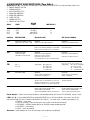
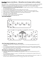
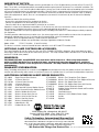
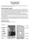
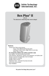
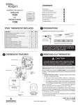
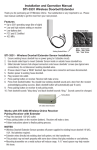
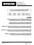
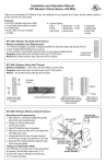
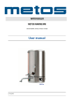
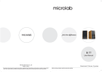
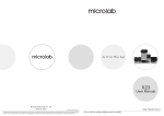
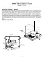
Installation and ZONES:
Operation Manual
LEFT BUTTON
SW4
SW5
SIREN
TIME
OFF
ON
OFF
ON
OFF
OFF
ON
ON
DISABLED
30 SEC
180 SEC
ON CONT
STI 8-Channel Receiver
“CALL”
M
RIGHT BUTTON
“RESTORE”
ZONE:
Model: NO
STI-34108
ON
and OFF
BUTTONS
Thank you for purchasing this fine product. Your satisfaction is very important to us. Please read this manual carefully to get the
most from your new product.
HOW THE PRODUCT WORKS
STI offers multiple wireless products designed to alert you of several different conditions. The STI 8-CHANNEL RECEIVER is a
433 MHz radio signal receiver that allows you to monitor up to 8 different STI devices at a single, convenient location. When
placed in enroll mode, it allows you to select 1 of 8 different zones that will represent your STI device(s) best, and enrolls it
when the monitor detects the STI device’s wireless signal. The STI wireless device family uses a system that also ensures
other devices (not from STI)
are not enrolled or detected. There are no concerns of accidental enrollment, alerts or crosstalk.
ANTENNAS
The RECEIVER allows you to choose which devices shall have a latching memory condition, when selected during enrollment.
It also allows you to select turning on a siren, sounding a chime, triggering a normally open or normally closed switch or
turning on an external 12 VDC output. The STI 8-CHANNEL RECEIVER also acts as a console repeater when paired with other
STI 8-CHANNEL RECEIVERS to receive wireless transmissions
PUSH BUTTONin up to 4 other areas over long distances or around disruptive
DIPSWITCH
FUNCTIONS
terrain.
PIEZO
BEFORE YOU START
SWITCHES 1-8
DIPSWITCH
FUNCTIONS
Refer to this drawing to become familiar with all the parts.
ZONE L
ANTENNAS
ZONE LEDs
PUSH BUTTON
COVER
SCREW
PIEZO
SWITCHES 1-8
DIPSWITCH
FUNCTIONS
WIRE ROUTE
OPTION 1
ZONE LEDs
COVER
SCREW
FCC ID: TXL34108
MODEL #34108
IC: 6335A-34108
PLUGINADAPTER
12 V 500mA
EMBOSSED
INPUT AND
OUTPUTS
TRIGGERED OUTPUT PLUG
, 75mA
12V
PLUG IN ADAPTER
, 500mA
12V
WIRE ROUTE
OPTION 1
SURFACE FEET (x4)
(WALL MOUNTING HOLES)
FORM
SWITCH OUTPU
+
+
-
N.O.
COM
N.C.
EMBOSSED
INPUT AND
OUTPUTS
12V 500 mA
IN
12V 300 mA
OUT
Trigger
Output
12 V
75mA
SAFETY TECHNOLOGY INTERNATIONAL
WATERFORD, MI U.S.A.
REDDITCH, WORCESTERSHIRE UK
12V
TERMINA
OUTPUTS
12V
TERMINALS 300mA
FCC ID: TXL34108
MODEL #34108
IC: 6335A-34108
—1—
PLUGINADAPTER
12 V 500mA
EMBOSSED
INPUT AND
OUTPUTS
12V 500 mA
IN
12V 300 mA
OUT
Trigger
Output
12 V
75mA
SAFETY TECHNOLOGY INTERNATIONAL
WATERFORD, MI U.S.A.
REDDITCH, WORCESTERSHIRE UK
N.O.
COM
N.C.
INPUTS
12V
TERMINALS 500mA
WIRE ROUTE
OPTION 2
+
+
-
FORM C
SWITCH OUTPUTS
TRIGGERED OUTPUT PLUG
, 75mA
12V
PLUG IN ADAPTER
, 500mA
12V
SURFACE FEET (x4)
(WALL MOUNTING HOLES)
INSTALLATION GUIDE
Surface Installation:
1. Ensure mounting screws are removed.
2. Insert rubber feet (provided) into holes on bottom cover.
3. Route wires under the product.
Wall Mounted Installation:
1. Ensure rubber feet are removed.
2. Remove front cover screw.
3. Remove cover (be careful not to lose push button).
4. Mark mounting holes on wall using bottom cover as template.
5. Drill holes with 3/16” drill bit.
6. Insert wall anchors (provided).
7. Insert power cord and wires and route on the back.
8. Insert mounting screws (provided) into plastic washers (provided).
9. Insert mounting screws into PCB holes through back of cover.
10. Insert mounting screws into wall anchors and tighten.
11. Press fit push button onto the push button switch on the circuit board.
12. Insert top cover tabs into bottom cover slots.
13. Carefully close top cover ensuring the push button inserts into cover hole and antennas rest in the side cover grooves.
14. Insert front cover screw and tighten.
15. Plug in AC adaptor.
1 - MIRROR MASTER OFF/ON
2 - NORMAL/ENROLL
3 - AUTO RESTORE/LATCH
4 - SIREN TIME/MIRROR#
5 - SIREN TIME/MIRROR#
6 - CHIME OFF/ON
7 - NORMAL/DELETE
8 - MIRROR SLAVE OFF/ON
If using for the first time or for enrollment adjustments, follow Zone Enrolling instructions. Otherwise, STI 8-CHANNEL
RECEIVER should be fully functional.
SW4
SW5
SIREN
TIME
MIRROR #
OFF
ON
OFF
ON
OFF
OFF
ON
ON
DISABLED
30 SEC
180 SEC
ON CONT
1
2
3
4
19018 ANCHOR
(4) PROVIDED
MARK AND DRILL
3/16 DIAMETER HOLES
(4) PLACES
PUSH BUTTON SWITCH
PUSH BUTTON
19081 FRONT COVER SCREW
19108 NYLON WASHER
(4) PROVIDED
19039 SCREW
(4) PROVIDED
—2—
COMPONENT DESCRIPTIONS (Top Side):
Switches (1- 8) - For reference, information is also written on the RECEIVER case (located under Zone ID list).
1 - MIRROR MASTER OFF/ON
2 - NORMAL/ENROLL
3 - AUTO RESTORE/LATCH
4 - SIREN TIME/MIRROR#
5 - SIREN TIME/MIRROR#
6 - CHIME OFF/ON
7 - NORMAL/DELETE
8 - MIRROR SLAVE OFF/ON
SIREN
SW4
SW5
TIME
MIRROR #
OFF OFFDISABLED
1
ON
OFF
30 SEC
2
OFF
ON
180 SEC
3
ON
ON
ON CONT
4
ON (Switch UP)
OFF (Switch DOWN)
Switch # DESCRIPTION SW1
MASTER RECEIVER SETTING
(Only active when SW8 = ON)
SW2 ENROLL DEVICES
SW3
ALARM LATCHING
(Only active while
SENSOR is being enrolled)
ENABLED
Switch on only for Mirror Master
DISABLED
Switch off if not Mirror Master ENABLED
DISABLED
LED for zone number waiting to enroll blinks. Normal Operation
Button used to change zone to be enrolled.
ENABLED LED turns on when triggered
Button press turns off siren
LED flashes when restored Second button press turns off LED flashing
SW4
RECEIVER # / SIREN TIME
RECEIVER# (when SW8 = ON) and
SW5
ON = 1 (SW4)(SW5) 00 = Mirror #1 OFF = 0 10 = Mirror #2 01 = Mirror #3 11 = Mirror #4 SW6 RECEIVER CHIME
SW7 SW8
DELETE DEVICES
MIRROR MODE ENABLED Chime sounds a double beep
when device is triggered.
DISABLED
LED turns on when triggered
LED turns off when restored
SIREN TIME (when SW8 = OFF) Note: Siren can turn off upon button press.
(SW4)(SW5)
00 = 0 Second (Silent)
10 = 30 Seconds
01 = 180 Seconds
11 = Continuously ON
DISABLED
Chime does not sound when
device is triggered.
ENABLED
DISABLED
All LEDs turn red. LED blinks for zone to be Normal Operation
deleted. Hold button for 5 seconds to delete.
Hold button another 5 seconds to delete all.
ENABLED
Enables Mirror Mode. Enables SW1. SW4/5 indicate RECEIVER#.
Turns on RECEIVER# (SW4/5) transmissions. DISABLED
Disables Mirror Mode. Disables SW1.
SW4/5 indicate ALARM TIME.
Turns off mirrored transmissions.
Push Button - Selects zone to enroll or delete, acknowledge latched alert (resets LED to GREEN), silences alarm.
LEDs (1- 8) - Each enrolled SENSOR or mirrored RECEIVER has an LED that indicates the current state of that
zone from the top LED (Zone 1) down to the bottom LED (Zone 8). The zone states, in order of precedence, are:
• LED RED = zone alarm
• LED RED (flashing) = zone latched (zone was in alarm and returned to normal)
• LED AMBER = SENSOR trouble (battery or SENSOR tamper trouble detected)
• LED GREEN = zone normal
• LED off = zone not enrolled
Sounder - Audio feedback for siren, chime/ beeps, zone enrollment and deletion.
—3—
COMPONENT DESCRIPTIONS (Bottom Side):
Adapter Plug Input - Input connector 12VDC, 500mA, center positive adapter (provided).
Triggered Output Plug (75mA) - 12VDC output connector. Activates with 12VDC, 75mA for 3 seconds when any zone
is triggered. Designed for use with STI Lamp Controller (STI-30104 sold separately).
Form C Switch Outputs (Dry Contacts) 30VDC, 1A Resistive
N.O. - Normally open circuit to COM terminal. Closed to COM when alarm is triggered.
COM - Common return between N.O. or N.C.
N.C. - Normally closed circuit to COM terminal. Open to COM when alarm is triggered.
When any zone has an alert signal received and the LED changes to continuous RED, a short circuit is made between the NO
and COM, and an open circuit is made between NC and COM. As soon as ALL zones are not in alert mode and the LED is no
longer continuous RED, an open circuit is made between NO and COM, and a short circuit is made between NC and COM.
12VDC Input (500mA)
+12VDC - Positive voltage input. Power input circuit rated to 500mA current.
-12VDC - Negative voltage input.
The 12VDC input terminals allow the RECEIVER to be powered from an external 12VDC, 500mA rated power source.
12VDC Output (300mA)
+12VDC - Positive output voltage. 300mA maximum output current.
-12VDC - Negative output voltage.
A continuous 12VDC output is produced only while sounder is activated. The 12VDC output terminals will turn on at the same
time as the onboard sounder in siren mode or chime mode.
NORMAL OPERATION
The RECEIVER receives 433 MHz radio signals from numerous STI sensors enrolled to the RECEIVER. It provides feedback in
the form of LED colors, onboard sounder annunciation, onboard sounder siren, switched on or off output terminals (Form C
contacts), a 3 second 12 VDC @ 75mA max. output on the triggered output plug and 12 VDC output terminals powered at the
same time as the onboard sounder.
LED Operation:
The LED status with higher importance is emitted by the LED. The LED importance is as follows (highest to lowest):
Red LED
- Zone enrolled, Alert status
Flashing Red LED - Zone enrolled, Latched and Non-Triggered status
Amber LED
- Zone enrolled, Tamper Alert and Non-Triggered status
Green LED
- Zone enrolled, Normal and Non-Triggered status
LED OFF
- Zone not enrolled
Onboard Sounder Operation:
Siren Mode – SW4 and SW5 (settings)
The onboard speaker gives a 4 KHz @ 90dB sound for the SIREN TIME set by SW4 and SW5 when any zone’s alert signal is
received (see Component Descriptions for siren times).
NOTE: Chime/Beep mode must be turned off, (SW6 OFF), for the siren mode to activate.
Chime/Beep Mode – (SW6 ON)
The onboard speaker gives a double beep when any zone’s alert signal is received. Chime/Beep mode overrides the siren mode.
Sensor Operation:
A SENSOR sends a 433 MHz radio signal to the RECEIVER that will indicate one or more of the following: Alert triggered;
restored to normal; sensor tampering; low battery; lost signal.
—4—
Low Battery / Tamper Detection / Out of Range SENSOR Alerts:
If the battery is too weak, something has triggered a tamper alert signal from the SENSOR, or the SENSOR has been out of range
between 12 - 24 hours, the zone LED will light AMBER to alert a need for attention to that device.
ZONE ENROLLING AND DELETING PROCEDURES
The STI 8-Channel Receiver is designed to receive ONLY wireless signals from products in the STI Alert Series (see back of
the installation instructions). The RECEIVER allows you to enroll up to 8 devices into zones 1 thru 8. The RECEIVER will enroll
from different SENSORS directly or by enrolling other mirrored RECEIVERS. The RECEIVER also enrolls up to eight keyfobs.
When ENROLL mode is enabled (SW2 ON), the LEDs for any currently enrolled zones will turn RED to indicate these zones
are not available. The LED will flash GREEN to indicate the available zone to be enrolled. Press the push button to change
to a different zone to be enrolled. The next available zone will have the flashing GREEN LED. The RECEIVER will not allow
enrollment into an occupied zone. The RECEIVER will not allow the same device to be enrolled into more than one zone.
The RECEIVER will not enter ENROLL mode while it is in DELETE mode (i.e. DIP SW7 ON).
Zone Latching:
“Latching” lets you know a zone alert was previously triggered but the alert has also been cleared. When a zone is in the
“latched” status, the zone LED will flash RED. For example, when a door SENSOR has been opened and closed, the zone LED
will flash RED to indicate the door was opened previously, but is no longer opened.
The latching is released when the user presses the push button to indicate acknowledgement of the alert. When the “latched”
status is released, the zone LED will change back to continuous GREEN. If the zone has another alert before the “latched”
status is released, the LED will change to continuous RED in the alert state, and then back to flashing when the alert is cleared. A zone will have “latching” when SW3 is (ON) at the time of enrollment. If zone latching is not selected at the time of enrollment
(SW3 OFF), the zone LED will change from continuous RED back to continuous GREEN when the alert has been cleared.
Enrolling Sensors into Zones:
1.
2.
3.
4.
5.
6.
7.
8.
Check that the module is not in DELETE mode (SW7 OFF).
If the zone should have “latching” set (SW3 ON).
Enable ENROLL mode set (SW2 ON).
Check that the zone flashing GREEN is correct, and note the zone(s) with RED LEDs.
Change the status of the SENSOR to be enrolled by triggering an alert on the SENSOR and return it to the non-triggered
state (if done manually).
The RECEIVER will give a double beep and the zone LED will change to continuous RED.
Repeat steps 2-6 to enroll another SENSOR.
To exit ENROLL mode set (SW2 OFF).
Sensor Installation Tip:
When first enrolling a SENSOR, set the “latching” on (SW3 ON), and bring the SENSOR to the RECEIVER location to enroll it
before mounting the SENSOR. Then, mount the SENSOR at its intended location and trigger an alert on the SENSOR. Check
the zone on the RECEIVER to see if it is continuous RED or flashing RED, which means it received the SENSOR’S signal. Then,
if latching is not desired, delete that zone (see Deleting Single Zones) and enroll the SENSOR again without latching (SW3
OFF), from the mounted location.
—5—
Keyfob Operation:
An STI Keyfob can be used to remotely turn off and on the LEDs, sounder, and outputs on the STI
8-Channel Receiver and also act as a CALL or MANUAL ALERT button. While the STI 8-Channel
Receiver is turned off, it will continue to monitor the sensor signals.
To use an STI keyfob, you can separately enroll the Left/Right buttons and ON/OFF buttons to the
receiver. To use a single STI keyfob with a Master + Mirror Receiver System, enroll the keyfob to
each receiver to be used in the system before adding the Mirrored receivers to the system. To use
multiple keyfobs to independently control each receiver, enroll each keyfob to its respective receiver
before adding the Mirrored receivers to the system.
ZONES:
LEFT BUTTON
“CALL”
RIGHT BUTTON
“RESTORE”
NO ZONE:
ON and OFF
BUTTONS
Enrolling Keyfob On/Off Buttons:
Keyfob ON/OFF buttons do not enroll into zones. The keyfob ON/OFF buttons will turn on and off all 8-Channel receiver outputs. Cycling these buttons remotely activates the push button.
1. Check that the module is not in DELETE mode (SW7 OFF).
2. Enable ENROLL mode set (SW2 ON).
3. Press either the ON or OFF button on the keyfob.
4. The RECEIVER will give a double beep. ON/OFF keyfob buttons will not be assigned to a zone LED.
5. Repeat steps 2-4 to enroll another keyfob.
6. To exit ENROLL mode set (SW2 OFF).
NOTE: The RECEIVER will only operate with 8 keyfob Left/Right buttons enrolled into zones and 8 keyfob ON/OFF buttons
enrolled into memory. If a ninth keyfob’s ON/OFF button is enrolled, the keyfob’s ON/OFF buttons enrolled first will be deleted.
ANTENNAS
Enrolling Keyfob LEFT/RIGHT Buttons:
Keyfob LEFT/RIGHT buttons enroll into a zone. The keyfob LEFT button is a CALL or MANUAL ALERT button and the RIGHT
button is a RESTORE. Follow the same steps for Enrolling Sensors into Zones and Deleting Single Zones for the Keyfob LEFT/
RIGHT buttons.
SWITCHES 1-8
DIPSWITCH
FUNCTIONS
Mirrored Receiver Operation:
The LEDs, the sounder, the siren time and the 12VDC output activation will duplicate the sensor settings enrolled on the master
RECEIVER. If a sensor is enrolled to a mirrored RECEIVER instead of the master, a transmission from the master RECEIVER will
override the mirrored RECEIVER’S LED status. To use any STI keyfob with a master + mirror RECEIVER system, enroll keyfob to
mirrored RECEIVER before adding the mirrored RECEIVER to a system.
ZONE LEDs
WIRE ROUTE
OPTION 1
FCC ID:
MODEL
IC: 633
SAFETY TECHNOLO
WATERFOR
REDDITCH, WOR
N.O.
COM
N.C.
+
+
-
EMBOSSED
INPUT AND
OUTPUTS
12V 500 mA
IN
12V 300 mA
OUT
Trigger
Output
12 V
75mA
The LEDs, the sounder, the siren time and the 12VDC output activation will duplicate the sensor settings enrolled on the master
RECEIVER. If LED “latching” is desired on the mirrored RECEIVER, this must be selected at the time of the mirrored RECEIVER’S
enrollment.
NOTE: If a SENSOR is enrolled to a mirrored RECEIVER in error (instead of the master), a transmission from the master RECEIVER
will override the mirrored RECEIVER’S LED status.
1. Check that the module is not in DELETE mode (SW7 OFF).
2. Use SW4 and SW5 to select the mirror number 1-4 if not the master (see Component Descriptions).
3. Enrolling mirrored RECEIVERS is performed in sequential pairs:
Pair Column A
Column B
1 Master => Receiver 1
2 Receiver 1 => Receiver 2
3 Receiver 2 => Receiver 3
4 Receiver 3 => Receiver 4
NOTE: All SENSORS are enrolled only to the master RECEIVER. The mirrored RECEIVERS copy the master RECEIVER’S output
(except latch settings) sequentially thru RECEIVERS 1 - 4.
4. Set SW1 and SW8 (ON) on the master RECEIVER.
5. Set SW8 (ON) on each mirrored RECEIVER.
6. Enable ENROLL mode, SW2 (ON), on the two RECEIVERS being paired together.
7. Press and release the Push Button on the Column A RECEIVER (above). The Column B receiver will give a double beep.
8. Press and release the Push Button on the Column B RECEIVER (above). The Column A RECEIVER will give a double beep.
NOTE: If Column B RECEIVER was previously enrolled to Column A RECEIVER and was not deleted, the Column A RECEIVER will
not double beep, but will work properly.
9. Disable ENROLL mode, SW2 (OFF), on both RECEIVERS.
10. Press and release the Push Button of the Column A RECEIVER (above). The LED’s of the Column B RECEIVER will light in
the same configuration.
NOTE: Keyfobs must be enrolled into each master or mirror RECEIVER where it will be used.
PLUGINADAPTER
12 V 500mA
Enrolling Mirrored (multiple) Receivers:
FORM C
SWITCH OUTPUTS
INPUTS
12V
TERMINALS 500mA
—6—
12
TE
BUTTON SWITCH
Enrolling Sensors into Master + Mirror ReceiverPUSH
Systems
(with or without
PUSH BUTTON
latching):
When using a master + mirror RECEIVER system, the latching feature is set independently on the master and/or mirror RECEIVERS.
Latching on the master and/or mirrored RECEIVERS is only set for a zone at the time the SENSOR is enrolled into the master
19081 FRONT COVER SCREW
RECEIVER. You will need to set (SW2 ON) and (SW3 ON or OFF) for each RECEIVER
at the time of SENSOR enrollment.
1. Check that each RECEIVER is not in DELETE mode (SW7 OFF).
19108 NYLON WASHER
2. Set desired “latching” on each system
RECEIVER.
(4) PROVIDED A RECEIVER set to (SW3 ON) will have latching. The RECEIVER set to (SW3
OFF) will only indicate the zone status.
19039 SCREW
PROVIDED
3. Set each RECEIVER to ENROLL mode, (SW2 ON), (4)
that
will store the latch setting.
4. Check that the zone flashing GREEN on the master RECEIVER is correct, and note the zone(s) with RED LEDs.
5. Trigger an alert on the SENSOR being enrolled and return it to the restored state (if restore is triggered manually).
6. The RECEIVER will give a double beep and the zone LED will change to continuous RED.
7. Repeat steps 2-6 to enroll another SENSOR.
8. To exit ENROLL mode, set (SW2 OFF) on the master RECEIVER.
9. Set all master and/or mirror RECEIVERS (SW3 OFF).
System Examples
SINGLE SYSTEM
Up to
1000 ft
Master
Receiver
Mirror #2
Receiver
Mirror #1
Receiver
MULTLIPLE SYSTEMS
Up to
1000 ft
Up to
1000 ft
Mirror #4
Receiver
- Last
Represents any STI 433 MHz sensor transmitting ONLY to a Master Receiver
SYSTEM 2
SYSTEM 1
Up to
1000 ft
Up to
1000 ft
Master
Receiver
Up to
1000 ft
Mirror #3
Receiver
Mirror #1
Receiver
Up to
1000 ft
Up to
1000 ft
Mirror #2
Receiver
- Last
Mirror #2
Receiver
- Last
Mirror #1
Receiver
Master
Receiver
Monitors Housed in a
Central Office or Location
DELETING SINGLE ZONES (Sensors and Keyfobs):
1. Enter DELETE mode (SW7 ON). All enrolled zone LEDs will turn RED. The first zone to be deleted will have the LED
flashing RED.
2. Press and release the push button to cycle the flashing LED through the zones until it reaches the zone to be deleted.
3. Press and hold the push button for 5 seconds to delete the zone with the flashing LED. The RECEIVER will give a single
beep and the LED will turn off. Release the push button.
DELETING ALL ZONES (Sensors, Mirrored Receivers and Keyfobs):
You must delete all zones in order to delete keyfobs and/or a mirrored RECEIVER.
1. Enter DELETE mode (SW7 ON). All enrolled zone LEDs will turn RED. The first zone to be deleted will have the LED
flashing RED.
2. Press and hold the push button for 5 seconds. The RECEIVER will give a single beep and the flashing LED will turn off. Continue to hold the push button.
3. After the first zone is deleted and while still holding the push button, all other enrolled zones will flash for 5 seconds. The
RECEIVER will give a double beep and all of the LEDs will turn off when those zones are deleted.
—7—
IMPORTANT NOTICE:
This product has been tested and complies with the specifications for a Class B digital device, pursuant to Part 15 of the FCC
Rules. These limits are designed to provide reasonable protection against harmful interference in a residential installation. This
equipment generates, uses, and can radiate radio frequency energy and, if not installed and used according to the instructions,
may cause harmful interference to radio communications. However, there is no guarantee that interference will not occur in
a particular installation. If this equipment does cause harmful interference to radio or television reception, which is found by
turning the equipment off and on, the user is encouraged to try to correct the interference by one or more of the following
measures: - Reorient or relocate the receiving antenna - Increase the separation between the equipment or devices - Connect the equipment to an outlet other than the receiver’s - Consult a dealer or an experienced radio/TV technician for assistance
Operation is subject to the following two conditions: (1) this device may not cause interference, and (2) this device must accept
any interference, including interference that may cause undesired operation of the device.
Changes or modifications not expressly approved by Safety Technology International, Inc. could void your authority to operate
this equipment.
To reduce potential radio interference to other users, the antenna type and its gain should be so chosen that the equivalent
isotropically radiated power (e.i.r.p.) is not more than that permitted for successful communication.
This product meets the applicable Industry Canada technical specifications. Le present materiel est conform aux specifications techniques applicables d’Industrie Canada.
Model: 34108
FCC ID: TXL34108 IC: 6335A-34108
This device is a wireless receiver intended for home and office use in all EU and EFTA member states.
OPTIONAL LAMP CONTROLLER ACCESSORY:
The Lamp Controller will turn on a lamp any time your STI 8-CHANNEL RECEIVER is triggered. Never come home to a dark
house again, and let others think you are home when you aren’t. The Lamp Controller works with both the STI-34150 (battery)
and the STI-34100 (solar) models.
WARNINGS:
FOR INDOOR USE ONLY. Keep RECEIVER away from water and/or damp areas. When using lamp controller
option, use ONLY 200 Watt or less incandescent lamps, and keep lamp away from bed coverings, curtains or
other flammable materials as this may present a fire hazard. The lamp controller CANNOT be used with 3-prong
grounded plugs.
WARRANTY INFORMATION:
Safety Technology International, Inc. warrants to the original consumer/purchaser that this product shall be free of defects in
material and workmanship under normal use and circumstances for a period of one (1) year from the original date of purchase.
ADDITIONAL WIRELESS ALERT SERIES PRODUCTS:
STI-34099
STI-34104
STI-V34104
STI-34108 STI-34188
STI-34101
STI-34151
STI-34201
STI-34301
STI-34401
STI-34501
STI-34601
STI-34701
STI-34751
Single Channel Slave Receiver
4-Channel Receiver
4-Channel Voice Receiver
8-Channel Receiver
8-Zone Relay Board
Solar Powered Driveway Monitor Sensor
Battery Powered Driveway Monitor Sensor
Wireless Mailbox Alert Sensor
Wireless Garage Sentry Sensor
Wireless Universal Alert Sensor
Wireless Pool Alert Sensor
Wireless Doorbell Button
Indoor Wireless PIR
Outdoor Wireless PIR
STI-6200WIR Wireless Fire Extinguisher Theft Stopper
STI-6200WIR4 Wireless Fire Extinguisher Theft Stopper w/Receiver
STI-6400WIR Wireless Exit Stopper Door Alarm
STI-6400WIR4 Wireless Exit Stopper Door Alarm with Receiver
STI-6517A
Stopper Station Shield with Sound
STI-6517B Stopper Station Shield with Sound and Transmitter
STI-30104
Lamp Controller
STI-30105
Extended Antenna
STI-34105
Voltamax 12VDC (500mA) Power Supply
STI-34106Keyfob
STI-34109Repeater
2306 Airport Rd • Waterford, MI 48327
Phone: 248-673-9898 • Fax: 248-673-1246
[email protected] • www.sti-usa.com
Safety Technology International (Europe) Ltd.
Unit 49G Pipers Road • Park Farm Industrial Estate • Redditch
Worcestershire • B98 0HU • England • Tel: 44 (0) 1527 520 999
Fax: 44 (0) 1527 501 999 • Freephone: 0800 085 1678 (UK only)
E-mail: [email protected] • Web: www.sti-europe.com
We Protect the Things that Protect You.
Inst. Sht. 8-Channel Wireless DEC2012