1
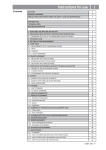
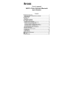
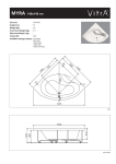
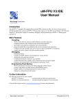
User’s manual
NOTICE 140X140 12 PAGES UK.indd 1
26/06/14 16:52
AUDIOPHILE INTEGRATED AMPLIFIER
Dear customer,
Thank you for purchasing a Micromega product. This unit provides ease of use
and sonics of the highest quality. Please pay close attention to this instruction
manual, and read it fully before attempting to operate. It is designed to ensure that you
maximise your pleasure of listening to MyAMP.
Checking
Check that the carton has no damage. Should you have any doubt about its
condition, please do not hesitate to contact your dealer. Opening the box, you
should find:
• C5 power chord
• Remote control handset and one CR2025 Lithium battery (do not forget to
remove the plastic protection for your battery).
Mains voltage
MyAMP mains power supply is designed to match the following mains voltage and
frequency range : 85-150 Vac / 47-63 Hz, or 180 ‑ 265 Vac / 47-63 Hz. Please
check that the voltage indicated on the label located above the ac inlet of your unit,
matches your home mains voltage. If not, DO NOT PLUG THE AC MAINS CHORD
and get in contact with your dealer. In any case, you will not be able to change
MyAMP ac mains voltage by yourself.
Interconnect cables
Except for the mains power chord, MyAMP is supplied without interconnect cables.
To get the most out of your unit, we strongly recommend to use good quality interconnect cables. MyCABLE offers a range of cables matching perfectly with MyAMP
quality requirements. We offer short cables, especially designed for My products as
well as Loudspeakers cables designed as the perfect complement of MySPEAKER,
the best match loudspeakers to MyAMP.
NOTICE 140X140 12 PAGES UK.indd 2
26/06/14 16:52
Wiring
MyAMP has 3 line level analog inputs AN1, AN2 and AN3, one USB 24/96
digital input, and two 24/192 SPDIF coaxial and optical inputs. Beside, MyAMP is
equipped with an aptX® Bluetooth module with outstanding sonic performance.
A pairing switch located on the back panel of the unit allows connecting many
different Bluetooth devices giving each one the possibility ot listening to its own
music on MyAMP.
A SUB output gives you the possibility to add an active subwoofer to your system
if needed. The RECORD ouput sends the analog signal content, just before the
volume control, to and external device such as a recorder or a processor.
MyAMP has also a trigger input to control the Standby / On status of the unit by a
5 to 12V DC trigger voltage. On the same connector you can also send, from an
external system, RC5 remote control codes to access directly all MyAMP functions.
The TRIG/IR IN connector wiring diagram as well as the list of remote control codes
is available on our web site under MyAMP/Support.
On MyAMP front panel your will find a 3.5mm headphone socket. When inserting
a headphone jack the loudspeakers are muted and the headphone volume control
setup becomes independent from the loudspeakers one.
NOTICE 140X140 12 PAGES UK.indd 3
26/06/14 16:52
MyAMP power amplifiers operate in class AB, thus needing a heatsink. MyAMP is
cooled by forced convection, thanks to an extremely quiet fan and a proprietary
extrusion profile designed by Micromega. This profile can be seen on each side of
the unit. Despite the fact that MyAMp is fully protected against abnormal heatsink
temperature rise, it is strongly recommended to allow 10cm minimal free space on
the left and right sides of the unit. This way, the air flow from left to right will not
suffer any constraints.
You can install MyAMP in a closet as long as it is equipped with air input and output
with sufficient surface and a good ventilation to avoid any air temperature rise that
would trigger MyAMP over temperature protection system.
The following diagram gives you an example how to connect different units
to MyAMP.
Powering up
Once having connected all your system units to MyAMP, you can now plug in the
ac line chord supplied with the unit.
MyAMP is now in “Standby” mode indicated by a red led located below the MyAMP
logo on the bottom left hand side of the unit front panel.
MyAMP meets the latest environment energy regulations and requires less than
500mW in “Standby” mode, making unnecessary the use of a power switch,
removing the electrical stress at each turn on and off will lengthen the life of components.
The stanby red led is also used as remote control reception indicator.
NOTICE 140X140 12 PAGES UK.indd 4
26/06/14 16:52
Front panel description
On the left hand bottom side of the front panel, you will find the MyAMP logo with
the red “Standby” led located just below.
In the middle of the unit, from bottom to top you will find the 3.5mm headphone
jack, with the IR received just above and a vertical row of 10 leds. The first led, just
avove the IR receiver is the red “Mute” led. Then 8 white leds indicate the volume
level and finally at the top of the row another red led indicate clipping when blinking and maximum level when always on.
On the right side of the front panel, from bottom to top, there are 3 control tact
switches “SEL”, “VOL-” and “VOL+”. Three white leds indicating analog input selection “AN1”, “AN2” and “AN3” are located above the tact switches and then three
other white ones used to indicate digital input selection “USB”, “OPTO” and “COAX”.
Finally at the top of the right side of the front panel a Bluetooth logo is framed on
the left by a red led and on the right side by a blue one. Please read the Bluetooth
paragraph for more details about MyAMP bluetooth input.
NOTICE 140X140 12 PAGES UK.indd 5
26/06/14 16:52
Exemple de schéma de raccordement
Recepteur sat. /Sat rec
CD - DVD - BD player
Digital Outputs
Tuner FM
Digital Outputs
AN1
AN2
AN3
REC.OUT
SUB.OUT
LEFT
BT PAIR
RIGHT
+
Téléphone
Smartphone
RIGHT
—
—
NOMINAL SPEAKERS IMPEDANCE > 4 Ohms
Enceinte
Speaker
NOTICE 140X140 12 PAGES UK.indd 6
LEFT
26/06/14 16:52
+
r sat. /Sat receiver
BD player
Digital Outputs
Ordinateur
Computer
REC.OUT
SUB.OUT
OPTO
COAX
USB
TRIG/IR-IN
BT PAIR
AC MAINS
—
LEFT
MPEDANCE > 4 Ohms
+
MADE IN FRANCE
TV/LCD
NOTICE 140X140 12 PAGES UK.indd 7
26/06/14 16:52
Operation
MyAMP can be controlled by the three tact switches located at the bottom right hand side
of the front panel or by the remote control handset supplied with the unit.
A short pressure on the unit “SEL” key or “Standby” button of the remote control handset
takes MyAMP out of “Standby” mode.
A 15 seconds waiting period has been implemented to allow the complete stabilization of
the internal circuitry as well as perfect silent operation. During this period, where the red
“Standby” led is blinking slowly, no operation is allowed.
Once out of standby, the mute led goes off and the unit selects AN1 or the latest selected
source before going into standby with the volume set to a minimal level. A long pressure
(more that 2 seconds) on the “SEL” key or a short press on the “Standby” button of the
remote control handset, places MyAMP in Standby mode again.
You can select the proper volume level by pressing on the VOL- and VOL+ keys on the unit
on the remote control handset. A long press on each volume key gives you the possibility
to increase or decrease rapidly the volume. When increasing rapidly the ramp will stop at a
predefined level, loud enough but not too loud to damage any speaker. Once that level is
reached, if you want to increase the volume you will have to do it step by step.
To select another source than the selected one, press on the “SEL” key of the unit until the
desired source is reached or use the direct access keys of the remote control handset. Each
time a source is changed, MyAMP goes into mute for 500ms to avoid any switching noise.
When selecting a digital source, MyAMP will unmute when a correct digital stream is received. Otherwise , the unit will stay muted with the red mute led on, and no change in the
previous volume setup possible to avoid unexpected level changes.
Bluetooth input
MyAMP is equipped with an aptX® Bluetooth module.
NOTICE 140X140 12 PAGES UK.indd 8
26/06/14 16:52
The Bluetooth input is indicated on MyAMP front panel by a Bluetooth logo framed by two
leds, a red one on the left side and a blue one on the right.
When selecting the Bluetooth input for the first time, MyAMP is in pairing mode , the red
and blue leds will flash alternatively. You should now be able to see MyAMP in the list of
Bluetooth units on your Bluetooth device. Connect your device to MyAMP following your
device connection procedure. Once connected, MyAMP front panel indicator will change
status: the red led will switch off and the blue led will flash every 2 seconds. From your
Bluetooth device you can start sending music to MyAMP. As soon as MyAMP will receive
a valid data stream the front panel blue led will stop blinking and will stay on as long as
MyAMP receives music.
You can connect up to 8 different Bluetooth units to MyAMP, actually, allowing every
member of the family to listen to its own music.
To connect a new device to MyAMP you must enter pairing mode first. To access pairing
mode, a microswitch is located on the back panel of the unit indicated by BT/PAIR. Using a
toothpick or any similar object , press at least 2 seconds on the pairing switch. On the front
panel, the red and blue leds will flash alternatively indicating that you have entered pairing
mode. You should be able now to see MyAMP in the list of Bluetooth devices on your
Bluetooth unit. Connect your device to MyAMP following your device connection procedure.
Once connected, MyAMP front panel indicator will change status, the red led will switch off
and the blue led will flash every 2 seconds.
Once 8 devices have already been paired to MyAMP, if you try to pair an additional device
the first one that was paird to MyAMP will be erased and replaced by the new one. You can
always decide to erase the list of devices that were connected to MyAMP Bluetooth module.
To do so, you need to press the pairing switch for more that 10 seconds and the Red led will
blink 5 times on the row indicating that the memory was erased.
To guarantee MyAMP musical reproduction integrity, the Bluetooth module is only powered
when selected, avoiding any interaction between analog and digital signals. You will need to
connect your Bluetooth device to MyAMP again when you select the Bluetooth input.
NOTICE 140X140 12 PAGES UK.indd 9
26/06/14 16:52
Below you will find a shortlist of MyAMP Bluetooth status indications.
Bluetooth Leds
Status
Blue led: ON 2 sec, OFF 1 sec
There is no Bluetooth unit connected to MyAMP
Blue and Red leds blink alternatively
MyAMP is in Pairing mode
Blue led flashes every 2 seconds
A Bluetooth device is connected to MyAMP
Red led flashes 5 times on the row
Module memory has been cleared
Blue led : ON
MyAMP is receiving music
TECHNICAL CHARACTERISTICS
Audio characteristics
Analog Inputs
Coaxial SPDIF input Optical SPDIF input
USB input Bluetooth aptX® Module
SPDIF sampling frequencies USB sampling frequencies USB / SPDIF / BLUETOOTH resolution Max Bluetooth sampling frequency Bluetooth pairing capacity Power / 8Ω
Power / 4Ω
Recommended load impedance
THD+ Noise (10W/1 kHz/8Ω)
Damping factor
Alimentation électrique
Type of mains cord Mains voltage range Mains frequency range Standby power consumption (85-265 Vac) Dimensions
Unit (L x P x H mm) Packaging (L x P x H mm) Poids
Unit Packaging NOTICE 140X140 12 PAGES UK.indd 10
3 x (250mV / 1MΩ)
1 x (> 0.2v p-p / 75Ω)
1 x (Toslink)
1 x (class1.0)
BT 3.0
32 kHz – 192 kHz
44.1 kHz – 96 kHz
16 – 24 bits
48 kHz
8
30 W
60 W
> 4Ω
≤ 0,003%
> 100 up to 1kHz
C5
85 – 150 V ac or 180 – 265V ac
47 – 63 Hz
< 500 mW
140 x 165 x 75
325 x 210 x 150
1 kg
1,5 kg
26/06/14 16:52
Cleaning of the unit
1. Unplug MyAMP from AC mains.
2. Using a soft cloth, gently wipe out the dust from MyAMP surfaces. To avoid any damage
to the product, never use any solvent or cleaning product containing solvent such as
acetone,trichloroethylene, ...Never use any abrasive material to clean MyAMP.
3. Once MyAMP has been cleaned you can connect the unit to the AC mains again.
Working conditions
Working temperature : from 0° à 35° C (32° à 95° F)
Storage temperature : from -25° à 60° C (-13° à 140° F)
Relative humidity (working) : from 20 % à 80 %
Relative humidity (storage) : from 10 % à 90 % (without condensation)
Warning
To reduce the risk of fire or electrical shock, do not expose MyDAC to rain or moisture
Recommendations
• Do not use MyAMP near water.
• Do not place objects filled with liquid on or near MyAMP.
• Do not place MyAMP near any heat sources such as radiators, stoves or other heatgenerating products including open flames.
• Disconnect MyAMP during lightning storms or when unused for extended periods.
• Refer all service-related issues to qualified personnel.
WARANTY
Your MyAMP is covered by a one year warranty from the date of purchase. f the device requires servicing, return it to the dealer you purchased it from, packed in the original box along
with the purchase invoice.The warranty covers manufacturing defects, with the exception of
any other damage resulting from:
• An accident, Negligent use, Poor handling • Bad installation and or failure to comply with the
instructions in the present manual • Any servicing carried out by a non-authorized personnel
• Damage during transport (the damage will not be covered by the transporter unless you
express the usual type of legal reservation indicating any damage on delivery).
NOTICE 140X140 12 PAGES UK.indd 11
26/06/14 16:52
!!! IMPORTANT !!! CUSTOMER CARE SAFETY INSTRUCTIONS
IMPORTANT
Please read all instructions before proceeding. If you have any questions
about the operation or use of this product, please contact your dealer.
PRODUCT SAFETY
This unit was designed and manufactured to ensure personal safety. Improper use can result in potential electrical shock or fire hazards. Please retain
these instructions for future reference.
The lightning flash with arrowhead symbol within the equilateral triangle is
intended to alert the user to the presence of non- isolated dangerous voltage
within the product’s enclosure that may be of sufficient magnitude to constitute a risk of electric shock.
CAUTION
To prevent the risk of electrical shock do not remove enclosure or disassemble. No user-serviceable parts inside. Refer servicing to qualify service
personnel. The exclamation point within an equilateral triangle is intended
to alert the user to the presence of important operating, maintenance and
servicing instructions in the literature associated with this device.
AUDIS sarl, 13-15 rue du 8 Mai 1945, 94470 Boissy Saint Leger, FRANCE
Fax: +33(0)1 4382 6128 – www.micromega-hifi.com – VAT: FR07500331301
NOTICE 140X140 12 PAGES UK.indd 12
26/06/14 16:52