1
Chapter 1 General Information
Kilomux-2100/2104 Installation and Operation Manual
•
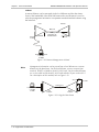
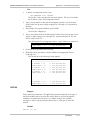
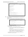
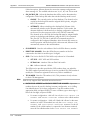
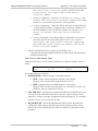
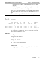
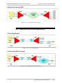
Using a RADview network management station or TELNET via a SLIP
connection to the remote Kilomux. The remote Kilomux requires an IP
address. For information on assigning an IP address, refer to the DEF AGENT
command in the Command Set Description appendix.
•
Using an ASCII terminal via a modem connection to the SP port.
Diagnostic Capabilities
The Kilomux system provides extensive diagnostics, supervision and maintenance
capabilities for easy maintenance and rapid detection and location of faults.
Kilomux diagnostics include automatic self-test upon power-up, and on-line
monitoring of critical functions. The system generates time stamped alarm
messages that cover all the significant system events. The time stamp is provided
by a real-time clock with battery backup. The system operator can then perform
comprehensive testing on each type of module, to determine the cause of the
alarm messages and return the system to normal operation.
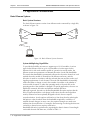
Various types of test loops are provided, including modem loops 2 and 3 per
ITU-T Rec. V.54 for rapid isolation of the fault area, tone injection for rapid testing
of voice interface modules, and pseudo-random sequence transmission test for
checking the proper operation of data interface modules, and detection of bit
errors.
1.2 Physical Description
Kilomux-2100, General Description
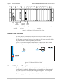
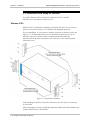
The Kilomux-2100 system consists of a 19" (3U) enclosure that contains 18 module
slots. Five of the slots (slots 1 through 5) are assigned to the system modules:
•
The control subsystem
•
The main link (aggregate) interface subsystem
•
The system power supplies.
Two slots each are assigned for KML and KPS modules, respectively, to provide
support for the redundancy option:
•
Slots 1 and 2 - for KPS modules
•
Slots 3 and 4 - for KML modules.
One slot (slot 6) is assigned for an options module (e.g., for the KDI or KAI
modules). The other 12 slots are intended for I/O modules. Each I/O slot can
accept any type of I/O module. All the modules are inserted through the rear
panel. The cable connections are also made through the rear panel.
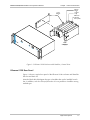
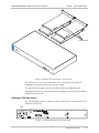
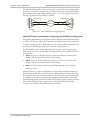
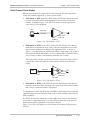
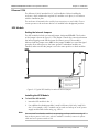
Figure 1-3 shows a general view of a Kilomux-2100, and identifies the functions of
the enclosure slot.
1-6
Physical Description