1
User Manual
NX64A Digital Radio
Doc. 602-11060-01 R: C
Released May 2000
NX64A Manual Doc #602-11060-01 R: C
SECTION
DWG
Table of Contents
Revision Configuration:
REV
ECO
REVISED/
RELEASED
602-11060-TOC
C
DCO1081
May 2000
1
602-11060-11
C
DCO1081
May 2000
2
602-11060-21
C
DCO1081
May 2000
3
602-11060-31
C
DCO1081
May 2000
4
602-11060-41
C
DCO1081
May 2000
5
602-11060-51
C
DCO1081
May 2000
6
602-11060-61
C
DCO1081
May 2000
Appendix
602-11060-AA1
C
DCO1081
May 2000
Table of Contents
i
Table of Contents
Section
Contents
Page
Table of Contents
List of Figures
List of Tables
Glossary
i
vi
viii
ix
1
System Characteristics
1.1
1.2
1.3
1.3.1
1.3.2
1.3.3
1.4
1.4.1
1.4.2
1.4.3
1.4.3.1
1.4.3.2
1.4.3.3
1.4.3.4
1.4.3.5
1.4.3.6
1.4.3.7
1.4.3.8
1.4.3.9
1.4.3.10
1.4.3.11
Introduction
System Features
System Specifications
System
Transmitter
Receiver
System Description
NX64A Digital Radio Product Structure
System Overview
Module Subsystem Description
CPU/Modem Motherboard
Transmitter Module
Digital Receiver Module
Front Panel
Power Supply Module
Data Interface Cards
Duplexers
Digital Multiplexer Module (Option)
Remote I/O (Option)
Remote Metering (Option)
FEC—Forward Error Correction (Option)
1-2
1-3
1-7
1-7
1-9
1-10
1-12
1-12
1-13
1-15
1-17
1-20
1-22
1-26
1-26
1-26
1-27
1-27
1-28
1-28
1-28
Continued on following page...
NX64A
602-11060-TC1 R: C
Table of Contents
Section
Contents (continued)
Page
2
2.1
2.2
2.3
2.3.1
2.3.2
2.3.2.1
2.3.2.2
2.4
2.4.1
2.4.2
2.4.3
2.4.4
2.5
2.5.1
2.5.2
2.5.3
2.5.3.1
2.5.3.2
2.5.4
2.5.4.1
2.5.4.2
2.5.5
2.5.6
2.5.6.1
2.5.6.2
2.5.7
2.5.8
2.5.8.1
2.5.8.2
2.6
2.6.1
2.6.2
2.6.3
2.6.4
2.6.5
2.7
2.7.1
2.7.2
2.7.3
2.7.4
2.8
Installation
Introduction
Unpacking/Inspection/Inventory
Pre-Installation Testing
Warnings
Loopback Tests
Local Loopback Testing
Remote Loopback (End-to-End) Testing
Interconnection to Other Equipment
Timing
Repeater Connections
NX64A to SDM-T (ACT)
NX64A to Kilomux (RAD)
Standby Configuration
Rack Installation
Power Supply
Equipment Interconnection-NX64A
External Duplexer (*preferred)
Internal Duplexer
Hot/Cold Standby Modes
Hot Standby (*preferred)
Cold Standby
NX64 Receiver Operation
TP64 Front Panel Controls and Indicators
LED Indicators
TRANSFER Switches
Master/Slave Operation & LED Status
Software Settings
NX64A Clock Settings
NX64A Control Settings
Site Installation
Physical and Environmental Considerations
Power Requirements
RF Connections
Data Connections
Rack Mount Installation
Antenna/Feed System
Antenna Installation
Transmission Line Installation
Testing
Environmental Seals
Link Alignment
2-3
2-3
2-5
2-7
2-8
2-9
2-11
2-13
2-13
2-21
2-23
2-25
2-27
2-27
2-27
2-28
2-28
2-29
2-30
2-30
2-30
2-30
2-30
2-31
2-31
2-31
2-33
2-33
2-33
2-34
2-35
2-36
2-36
2-36
2-37
2-38
2-38
2-38
2-39
2-40
2-41
ii
Continued on following page...
NX64A
602-11060-TC1 R: C
Table of Contents
Section
Contents (continued)
3
Operation
3.1
3.2
3.2.1
3.2.2
3.2.3
3.3
3.4
3.4.1
3.4.2
3.4.2.1
3.4.2.1.1
3.4.2.1.2
3.4.2.1.3
3.4.2.1.4
3.4.2.1.4.1
Introduction
Front Panel Operation
LCD Display
Cursor and Screen Control Buttons
Status Indicators
Screen Menu Overview
Screen Menu Summary
Controls Menu
Status Menu
Status Unit Selection
“This Unit” Fault Status
“This Unit” Transmitter (Tx) Status
“This Unit” Receiver (Rx) Status
“This Unit” Modem Status
FER vs. Post-FEC BER
Discussion
“This Unit” System Status
“Remote Unit” Fault Status
“Remote Unit” Transmitter (Tx) Status
“Remote Unit” Modem Status
Configuration Menu
Clock Source
Data Rate Screen
RTS/CTS Delay
FEC (Forward Error Correction)
RF Frequency (Limited Access)
Test Menu
Test Unit Selection
“This Unit” Test Menu
“Remote Unit” Test Menu
Configure/Calibrate Menu (Limited Access)
Configuration
Data Rate
Efficiency, Etc
Mod, Demod
Step, Filt, LO FR, AGC
Hide
Calibration
Factory Values
3.4.2.1.5
3.4.2.2.1
3.4.2.2.2
3.4.2.2.3
3.4.3
3.4.3.1
3.4.3.2
3.4.3.3
3.4.3.4
3.4.3.5
3.4.4
3.4.4.1
3.4.4.2
3.4.4.3
3.4.5
3.4.5.1
3.4.5.1.1
3.4.5.1.2
3.4.5.1.3
3.4.5.1.4
3.4.5.1.5
3.4.5.2
3.4.5.3
iii
Page
3-3
3-4
3-4
3-5
3-5
3-6
3-9
3-9
3-11
3-11
3-12
3-13
3-14
3-15
3-16
3-18
3-20
3-21
3-21
3-22
3-22
3-23
3-24
3-24
3-25
3-27
3-27
3-27
3-28
3-29
3-29
3-29
3-29
3-30
3-30
3-31
3-31
3-31
Continued on following page...
NX64A
602-11060-TC1 R: C
Table of Contents
Section
Contents (continued)
4
Applications
4.1
4.2
4.3
4.4
4.5
4.6
4.7
4.8
4.9
Introduction
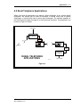
Rural Telephone Applications
Multichannel Application
Private Telecom Application
ISDN Application
VSAT Tail Circuit Applications
Compressed Video Application
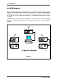
ATM Network
Mobile Public Safety Application
5
System Planning & Engineering
5.1
5.1.1
5.1.2
5.1.3
5.1.4
5.1.5
5.2
5.2.1
5.2.2
5.2.3
5.2.4
5.2.5
5.2.6
5.2.7
5.3
5.3.1
5.3.2
5.3.3
Introduction
Line of Sight
Refraction
Fresnel Zones
K Factors
Path Profiles
Path Analysis
Overview
Losses
Path Balance Sheet/System Calculations
Path Availability and Reliability
Methods of Improving Reliability
Availability Requirements
Path Calculation Balance Sheet
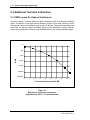
Additional Technical Information
BER versus Co-Channel Interference
BER versus Adjacent Channel Interference
Interference for 10E-4 BER—Co-Channel and
Adjacent Channels
BER versus SNR at Receiver Output
SNR versus Signal Level
RSSI versus Signal Level
Spectral Occupancy
5.3.4
5.3.5
5.3.6
5.3.7
iv
Page
4-2
4-3
4-4
4-5
4-6
4-6
4-7
4-8
4-9
5-2
5-2
5-2
5-2
5-4
5-6
5-6
5-6
5-7
5-7
5-10
5-12
5-12
5-13
5-14
5-14
5-15
5-16
5-17
5-18
5-19
5-20
Continued on following page...
NX64A
602-11060-TC1 R: C
Table of Contents
Section
Contents (continued)
6
Customer Service
6.1
6.2
6.3
6.4
Introduction
Technical Consultation
Factory Service
Field Repair
Page
6-2
6-2
6-3
6-4
Appendix
A.
B.
C.
D.
Test Connector Schematics
Figure A-1 Loopback Test Connectors
Interface Cables Schematics
Figure B-1 NX64A/SDR-xx to V.35 Interface Cable
Figure B-2 NX64A to RS-449 Cable
Figure B-3 Null Composite I/O Cable
Figure B-4 NX64A/SDR-xx to RAD Kilomux Interface Cable
Figure B-5 NX64 to SPD-703 Interface Cable (DCE-DCE)
Figure B-6 NX64 to SPD-703 Interface Cable (DCE-DTE)
Figure B-7 Remote Metering Option Terminal Block
Figure B-8 G.703 Adaptor
Connector Pin Assignments
Figure C-1 Composite I/O
Figure C-2 STBY/XFER
Figure C-3 NMS Port
Figure C-4a Orderwire
Figure C-4b Remote Metering Option
Figure C-5 Remote I/O External Output
Figure C-6 Remote I/O External Input
Table C-1 RS-449 NX64A I/O Connections
Table C-2 V.35 NX64A I/O Connections
Table C-3 EIA530 I/O Connections
Table C-4 RS-232 I/O Connections
Table C-5 G.703 I/O Connections
Table C-6 FEC Switch Settings
Manufacturer’s Data Sheets
NX64A
602-11060-TC1 R: C
A-2
A-2
A-3
A-3
A-4
A-5
A-6
A-7
A-8
A-9
A-10
A-11
A-11
A-12
A-12
A-13
A-13
A-14
A-14
A-15
A-16
A-17
A-18
A-19
A-19
A-20
v
Table of Contents
vi
List of Figures
Figure
Title
Page
1-1
1-2
1-3
1-4
1-5
1-6
System Overview Diagram
System Block Diagram
Transmitter Block Diagram
RF Down Converter Block Diagram
Digital Down Converter Block Diagram
Functional Block Diagram of the Moseley Programmable Down
Converter
MSB Adjustment Circuitry
Shipping Strap Removal
Rear Panel I/O Ports and Controls
Local Loopback Test Setup
Remote Loopback Test Setup
Conceptual Diagram NX64A Modem Internal Data/Clock Timing
Conceptual Diagram NX64A FEC Internal Data/Clock Timing
NX64A Data/Clock Timing. Example 1.
NX64A Data/Clock Timing. Example 2.
NX64A Data/Clock Timing. Example 3.
NX64A Data/Clock Timing. Example 4.
NX64A Repeater Interconnection
NX64A Interconnection to SDM-T
NX64A Interconnection to RAD Kilomux
External Duplexer Configuration
Internal Duplexer Configuration
TP64 Front Panel
Site Installation Details
Rack Mount Bracket Installation
Antenna/Feed System Testing
Front Panel Display and Controls
Screen Menu Flowchart
Rural Telephone Applications
Multichannel Application
Private Telecom Application
ISDN Application
VSAT Tail Circuit Applications
Compressed Video Application
ATM Network
Mobile Public Safety Application
BER versus Co-Channel Interference
BER versus Adjacent Channel Interference
Interference for 10E-4 BER—Co-Channel and Adjacent Channels
BER versus SNR at Receiver Output
1-14
1-16
1-20
1-22
1-23
1-24
1-7
2-1
2-2
2-3
2-4
2-5
2-6
2-7
2-8
2-9
2-10
2-11
2-12
2-13
2-14
2-15
2-16
2-17
2-18
2-19
3-1
3-2
4-1
4-2
4-3
4-4
4-5
4-6
4-7
4-8
5-1
5-2
5-3
5-4
1-24
2-4
2-5
2-10
2-12
2-14
2-15
2-15
2-16
2-16
2-17
2-22
2-23
2-25
2-28
2-29
2-30
2-35
2-37
2-40
3-4
3-7
4-3
4-4
4-5
4-6
4-6
4-7
4-8
4-9
5-14
5-15
5-16
5-17
Continued on following page...
NX64A
602-11060-TC1 R: C
Table of Contents
List of Figures (continued)
Figure
Title
Page
5-5
5-6
5-7
5-8
5-9
A-1
B-1
B-2
B-3
B-4
B-5
B-6
B-7
B-8
C-1
C-2
C-3
C-4a
C-4b
C-5
C-6
SNR versus Signal Level
RSSI versus Signal Level
Spectral Occupancy, High Sensitivity Mode
High Efficiency Mode
Narrow Bandwidth Mode
Loopback Test Connectors
NX64A/SDR-xx to V.35 Interface Cable
NX64A to RS-449 Cable
Null Composite I/O Cable
NX64A/SDR-xx to RAD Kilomux Interface Cable
NX64 to SPD-703 Interface Cable (DCE-DCE)
NX64 to SPD-703 Interface Cable (DCE-DTE)
Remote Metering Option Terminal Block
G.703 Adaptor
Composite I/O
STBY/XFER
NMS Port
Orderwire
Remote Metering Option
External Output
External Input
5-18
5-19
5-20
5-21
5-21
A-2
A-3
A-4
A-5
A-6
A-7
A-8
A-9
A-10
A-11
A-12
A-12
A-13
A-13
A-14
A-14
NX64A
602-11060-TC1 R: C
vii
Table of Contents
List of Tables
Table
Title
Page
1-1
1-2
1-3
2-1
2-2
2-3
2-4
2-5
2-6
3-1
3-2
5-1
5-2
5-3
5-4
5-5
5-6
5-7
Occupied Bandwidth
BER Threshold, 1 x 10⁻³ at Rx Input, High Sensitivity
BER Threshold, 1 x 10⁻³ at Rx Input, High Efficiency
NX64A Repeater Clock Settings
Clock Settings - NX64A to SDM-T (NX64A Source)
Clock Settings - NX64A to SDM-T (SDM-T Source)
Clock Settings - NX64A to Kilomux
TP64 Transmitter Master/Slave Logic
TP64 Receiver Master/Slave Logic
LED Status Indicator Functions
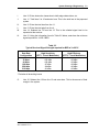
Data Rate vs. Channel Spacing
Typical Antenna Gain
Free Space Loss
Transmission Line Loss
Branching Losses
Typical Received Signal Strength required for BER of 1x10E-3
Relationship Between System Reliability & Outage Time
Fade Margins Required for 99.99% Reliability, Terrain Factor of
4.0, and Climate Factor of 0.5
RS-449 NX64A I/O Connections
V.35 NX64A I/O Connections
EIA530 I/O Connections
RS-232 I/O Connections
G.703 I/O Connections
FEC Switch Settings
FEC Switch Settings
1-2
1-11
1-11
2-21
2-24
2-24
2-26
2-31
2-32
3-5
3-23
5-7
5-8
5-8
5-9
5-9
5-11
5-12
C-1
C-2
C-3
C-4
C-5
C-6A
C-6B
NX64A
602-11060-TC1 R: C
A-15
A-16
A-17
A-18
A-19
A-19
A-19
viii
Table of Contents
Glossary
A/D, ADC
Analog-to-Digital, Analog-to-Digital Converter
ADPCM
Adaptive Differential Pulse Code Modulation
AES/EBU
Audio Engineering Society/European Broadcast Union
AGC
Auto Gain Control
ATM
Automatic Teller Machine
BER
Bit Error Rate
Codec
Coder-Decoder
CSU
Channel Service Unit
D/A, DAC
Digital-to-Analog, Digital-to-Analog Converter
dB
Decibel
dBc
Decibel relative to carrier
dBm
Decibel relative to 1 mW
dBu
Decibel relative to .775 Vrms
DCE
Data Circuit-Terminating Equipment
DSP
Digital Signal Processing
DSTL
Digital Studio-Transmitter Link
DTE
Data Terminal Equipment
DVM
Digital Voltmeter
EMI
Electromagnetic Interference
ESD
Electrostatic Discharge/Electrostatic Damage
FEC
Forward Error Correction
FET
Field effect transistor
FMO
Frequency Modulation Oscillator
FSK
Frequency Shift Keying
FT1
Fractional T1
IC
Integrated circuit
IEC
International Electrotechnical Commission
IF
Intermediate frequency
ISDN
Integrated-Services Digital Network
kbps
Kilobits per second
kHz
Kilohertz
NX64A
602-11060-TC1 R: C
ix
Table of Contents
LED
Light-emitting diode
LO, LO1
Local oscillator, first local oscillator
LSB
Least significant bit
MAI
Moseley Associates, Inc.
Mbps
Megabits per second
Modem
Modulator-demodulator
MSB
Most significant bit
MUX
Multiplex, Multiplexer
µV
Microvolts
NC
Normally closed
NMS
Network Management System
NO
Normally open
PCB
Printed circuit board
PCM
Pulse Code Modulation
PGM
Program
R
Transmission Rate
RF
Radio Frequency
RSL
Received Signal Level (in dBm)
RSSI
Received Signal Strength Indicator/Indication
RX
Receiver
SCADA
Security Control and Data Acquisition
SNR
Signal-to-Noise Ratio
SRD
Step Recovery Diode
STL
Studio-Transmitter Link
THD
Total harmonic distortion
TTL
Transistor-transistor logic
TX
Transmitter
Vp
Volts peak
Vpp
Volts peak-to-peak
VRMS
Volts, root-mean-square
VSWR
Voltage standing-wave ratio
NX64A
602-11060-TC1 R: C
x
Section 1
System
Characteristics
Section
Contents
Page
1.1
1.2
1.3
1.3.1
1.3.2
1.3.3
1.4
1.4.1
1.4.2
1.4.3
1.4.3.1
1.4.3.2
1.4.3.3
1.4.3.4
1.4.3.5
1.4.3.6
1.4.3.7
1.4.3.8
1.4.3.9
1.4.3.10
1.4.3.11
Introduction
System Features
System Specifications
System
Transmitter
Receiver
System Description
NX64A Digital Radio Product Structure
System Overview
Module Subsystem Description
CPU/Modem Motherboard
Transmitter Module
Digital Receiver Module
Front Panel
Power Supply Module
Data Interface Cards
Duplexers
Digital Multiplexer Module (Option)
Remote I/O (Option)
Remote Metering (Option)
FEC—Forward Error Correction (Option)
1-2
1-3
1-7
1-7
1-9
1-10
1-12
1-12
1-13
1-15
1-17
1-20
1-22
1-26
1-26
1-26
1-27
1-27
1-28
1-28
1-28
NX64A
602-11060-11 R: C
1-2
System Characteristics
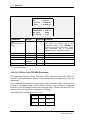
1.1 Introduction
The NX64A Digital Radio Link is a spectrum-efficient digital modem and radio offering a
high performance, reliable, and cost-effective alternative to leased lines and
conventional analog radios. Available in 297-512 MHz, 790-960 MHz and 1425-1535
MHz frequency bands, the NX64A is capable of transmitting 32-512 kbps over distances
up to 35 miles (55 kilometers).
The NX64A Digital Radio Link is available in five data rate configurations (see below).
Table 1-1
Occupied Bandwidth
Data Rate
(kbps)
High Efficiency*
Bandwidth (kHz)
High Sensitivity**
Bandwidth (kHz)
28/32
25
50
56/64
50
100
112/128
100
200
168/192
200
200
224/256
200
400
336/384***
200
400
448/512
400
Contact Factory
* High Efficiency (7 level modulation) = EFF 2 (2 bps/Hz)
** High Sensitivity (3 level modulation) = EFF 1 (1 bps/Hz)
*** 384 kbps in 200 kHz is a special US version
This efficiency serves to make the licensing of usable frequencies in a particular region
or area much easier.
With leading edge digital signal processing and error correction schemes, the NX64A
digital radios can provide error rate performance of 1×10E-8 over line-of-sight distances
of up to 35 miles (55 kilometers). The NX64A can be set up to transmit longer distances
by hops, with no degradation of voice and fax messages or corruption of data
communications.
Digital radios are increasingly favored throughout the world because they can be set up
quickly and easily, as temporary or as permanent installations. In developing countries
and in the industrial nations, both rural and urban networks are using digital radios when
other transmission facilities are unavailable, inappropriate, or too expensive. The NX64A
is especially well suited to these applications because it has been designed for today's
multimedia networking environment.
NX64A
602-11060-11 R: C
System Characteristics
1-3
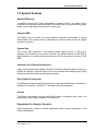
1.2 System Features
Spectral Efficiency
The NX64A requires only 50 kHz of bandwidth to transmit 64 kbps. This makes it twice
as efficient as most other radios available in the market place. A lower efficiency option
allows users to trade spectral efficiency for system gain.
Constant SNR
The NX64A does not suffer from fade problems generally encountered in analog
transmissions. Error performance is independent of received carrier power until digital
threshold is reached.
System Gain
The 30 dB SNR threshold of conventional analog radios and the 1×10E-4 error
threshold of the NX64A are the same. However, the NX64A delivers 50 dB SNR at
digital threshold. An analog system would require 20 dB more signal to deliver 50 dB
SNR.
Immunity to Co-Channel Interference
Unlike analog systems that typically require 50 to 60 dB co-channel protection ratios, the
NX64A can tolerate co-channel levels as low as 14 dB below the desired signal. Digital
modulation eliminates birdies and background chatter.
Direct Digital Connectivity
The NX64A eliminates the need for expensive modems and enables direct connection to
Switched 56, fractional T1/E1/CEPT-1, and basic rate ISDN equipment.
Access
The NX64A can transmit over the most difficult terrain—mountains, gulfs, rivers, and
jungle areas—where cable installation is not practical.
Degradation-Free Repeater Operation
Digital regeneration enables multi-hop transmission without signal degradation or the
need for equalization.
NX64A
602-11060-11 R: C
1-4
System Characteristics
Higher Data Speeds
The data throughput of analog radios is limited by modem technology. The highest rate
possible with current modems is 33.6 kbps. The NX64A can handle rates up to 512
kbps.
Mux Option
The optional SL9000DM personality module multiplexes four program channels for
simultaneous transmission. Use of two SL9000DM modules allows up to eight channels.
The digital data interface for each channel may be configured independently for V.35,
RS-449, or RS-232. Additionally, a Voice/Telco interface option is available for direct
connection to telephone circuits.
Network Management
Extensive NMS features are available for the NX64A. Real-time on-line and off-line
control along with analog and digital loopback are possible at both the local and remote
terminals. Event and alarm history can be reported over dial-up circuits, the front panel,
or the NMS host.
Service Channel
An optional built-in service channel that is available simultaneously with the composite
data can be used for maintenance and signaling.
Supervisory Control
In addition to the extensive NMS features, as an option the NX64A allows for telecontrol
of 4 status, 4 telemetry, and 6 command channels on each radio terminal. The NMS
channel can optionally be used as an auxiliary data channel.
Source Power Modularity
With modularized power supply options, the NX64A can be converted quickly for AC or
DC operation.
Low Power Consumption
The NX64A’s low power consumption allows cost-effective solar operation. Typically, the
NX64A consumes less than 45 watts (with standard 5 watt transmitter output and no
internal multiplexer module installed).
NX64A
602-11060-11 R: C
System Characteristics
1-5
Security
The radio frequency, modulation, coding, and scrambler circuits in the NX64A make
casual interception difficult. Wireline and standard analog FM radios are much more
susceptible to tapping.
Quick Payback
Built-in orderwire, alarm and control system, low power consumption, and reduced
antenna and transmission line costs will in themselves pay for the NX64A. Use of the
SL9000DM multiplexer module can eliminate the need for an expensive, separate
multiplexer. The modem and direct data connection savings are more application
specific. The NX64A is easy to install and does not require specialized equipment or
skills.
Applications
•
Integrated, single or multichannel voice, fax, and data communications
•
Last-mile tail circuits for VSAT/ISDN/Fractional T1/E1/CEPT-1
•
Compressed video for teleconference and security applications
•
•
Transmission of high-speed graphic data for CAD/CAM and interconnection
of LANs
Cost-effective alternative for bank ATM networks and efficient point-of-sale
mediums
•
Rural radio extensions for single- and multichannel access systems
•
High-speed SCADA, point-to-point, and point-to-multipoint networks
Typical End Users
•
Utilities and Oil & Gas pipelines
•
Banks
•
VSAT-based networks
•
National PTT
•
Private Telecom operators
•
Public safety organizations
NX64A
602-11060-11 R: C
1-6
System Characteristics
Additional Product Features
•
•
•
•
Microprocessor control and menu-driven operator panel facilitates userfriendly operation.
Available in 297-512 MHz band with 5 or 9 watt output; in 790-960 MHz band
with 5 watt output; in 1425-1535 MHz band with 1 watt output; and in 23002500 band with +20 dBm output.
Selectable data rate operation from 16 kbps to 512 kbps.
Selectable spectral efficiency of 1 and 2 bps/Hz. Allows tradeoff between
system gain and occupied bandwidth.
•
Adjustable Bit Error Threshold for monitoring transmission quality.
•
Programmable RTS/CTS delays from 1 to 1000 msec.
•
Full support for hot and cold standby operation.
•
Optional Forward Error Correction for burst-mode interferences.
NX64A
602-11060-11 R: C
System Characteristics
1-7
1.3 System Specifications
1.3.1 System
Frequency
297-512 MHz
790-960 MHz
1425-1535 MHz
2300-2500 MHz
Fully synthesized
No adjustments required within a 1 MHz band
Adjustable within a 20 MHz band without component changes
Tx-Rx Spacing
Internal duplexer limited to the following minimum spacings:
7 MHz
297-327 MHz
4.5 MHz
335-512 MHz band
9 MHz
790-960 MHz band
40 MHz
1425-1535 MHz band
Consult Factory for 2300-2500 MHz band
External duplexer required for smaller spacings
Frequency
Step Size
2.5 kHz to 25 kHz (programmable)
Data Rate
Selectable depending on IF bandwidth and efficiency setting:
16/19.2 kbps
28/32 kbps
56/64 kbps
112/128 kbps
168/192 kbps
224/256 kbps
336/384 kbps
448/512 kbps
Interface
V.35, RS-449, RS-232, EIA-530 (RS-530), G.703 (64/128 kbps)
Spectral
Efficiency
Selectable:
1 bps/Hz (3 level modulation/“High Sensitivity”/LOW EFF = 1)
2 bps/Hz (7 level modulation/“High Efficiency”/HIGH EFF = 2)
RTS/CTS Delay
1 ms to 255 ms (programmable)
Diagnostics
Local and remote loopback
Local and remote status and control
Monitoring of BER, RSL, alarms, status and historical
information
NX64A
602-11060-11 R: C
1-8
System Characteristics
1.3.1 System (Continued)
MUX
Digital Multiplexer
(Option)
8 HP personality module
4 channels per module (two modules may be installed)
Independent interface for each channel
Available mux interfaces:
V.35, Voice/Telco, RS-449, RS-232
NMS:
Network
Management
System (Option)
On line/off line
Full routing and configuration
Data Rate: 1200 bps (aux channel)
Local or remote via configured data path
Remote I/O
(Option)
6 command channels:
Programmable momentary, momentary pulse, or latching
Relay spec: 50V @ 2A
4 status channels:
Programmable N.O./N.C., momentary, or latching
alarm indication
TTL-compatible input standard
4 telemetry channels:
Programmable limit
Absolute, linear, power-to-linear conversion
Resolution: 8 bits
Temperature
Range
Full performance: 0 to 50°C
Operational: -30 to 65°C
Power Source
Power Consumption
<45W with 5W Tx output (nominal configuration)
<50W with 9W Tx output
<60W with 9W Tx and 1 SL9000DM module
<65W with 9W Tx and 2 SL9000DM modules
AC Input Module
Universal AC: 90 – 260 VAC, 47 - 63 Hz
DC Input Modules
±12 VDC: 10 - 20 VDC
±24 VDC: 18 - 36 VDC
±48 VDC: 36 - 72 VDC
Isolated chassis gnd standard (switchable to common)
Orderwire
(Option)
2-Wire/4-Wire Tel/Line level
Line levels Tx -16 dBm, Rx +7 dBm
E&M signaling
NX64A
602-11060-11 R: C
System Characteristics
1.3.1 System (Continued)
Remote Metering
(Option)
Forward Error
Correction:
(Option)
Allows remote access to front panel LED indications;
TTL compatible outputs (unbuffered)
RJ45 rear panel “Orderwire” connector
Coding:
Reed-Solomon, T=10
Auxiliary Data: Async, RS-232, Start, Stop, 8 data, WP, 300,
600, …, 4800.
Interface:
V.35, RS-499
1.3.2 Transmitter
Power Out
Standard:
5 Watts (37 dBm):
1 Watt (30 dBm):
+20 dBm:
Option:
9 Watts (40 dBm):
297-512, 790-960 MHz
1425-1535 MHz
2300-2500 MHz
297-512 MHz
Connector Type
50 Ohms type N (female)
Frequency
Stability
0.00025% (2.5 ppm); 0 to 50°C
1.5 ppm typical
1.0 ppm optional
Spurious
TX output:
-60 dBc
Post-duplexer: -70 dBc
Type of
Modulation
Continuous phase digital modulator
Suitable for use over non-linear amplifier
(Suitable for FM analog transmission)
NX64A
602-11060-11 R: C
1-9
1-10
System Characteristics
1.3.3 Receiver
Type of Receiver
Dual conversion superheterodyne
1st IF = 70 MHz nominal (= 69.3 MHz factory option;
determined by operating frequency)
2nd IF = 10.7 MHz
Image Rejection
80 dB (minimum)
Connector Type
50 ohm type N (female)
Demodulation
Baseband non-coherent discriminator detection
Data-coherent clock recovery
(Suitable for FM reception)
Frequency
Stability
0.00025% (2.5 ppm); 0 to 50°C
1.5 ppm typical
1.0 ppm optional
BER Threshold
Mute Adjust
Adjustable 1x10E-3 to 1x10E-8
(for TP64 Transfer Panel applications only)
NX64A
602-11060-11 R: C
System Characteristics
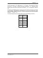
1-11
Table 1-2
BER Threshold, 1 x 10⁻³ at Rx Input
High Sensitivity (EFF=1, 3-Level Modulation)
DATA RATE
Rx input (dBm)
Channel bandwidth
spacing (kHz)
32 kbps
64 kbps
128 kbps
256 kbps
384 kbps
-104
-101
-98
-95
-93
50
100
200
400
512 kbps
400
Contact
factory
Notes:
Preselector loss of 4 dB and duplexer loss of 2 dB not included.
1 x 10⁻⁶ provides 3 dB more signal
Table 1-3
BER Threshold, 1 x 10⁻³ at Rx Input
High Efficiency (EFF=2, 7-Level Modulation)
DATA RATE
32 kbps
64 kbps
128 kbps
256 kbps
384 kbps
512 kbps
Rx input (dBm)
-96
-93
-90
-87
-84**
-84
Channel bandwidth
spacing (kHz)
25
50
100
200
200
400
Notes:
Preselector loss of 4 dB and duplexer loss of 2 dB not included.
1 x 10⁻⁶ provides 3 dB more signal
**Threshold less for FCC mask
NX64A
602-11060-11 R: C
1-12
System Characteristics
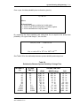
1.4 System Description
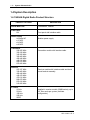
1.4.1 NX64A Digital Radio Product Structure
PRODUCT OPTIONS
DESCRIPTION
NX64A Base Unit
CPU/Modem, Chassis
Front Panel
NX
Front panel with interface cable
Power Supply
Universal AC
±12 VDC
±24 VDC
±48 VDC
Transmitter
290-305 MHz
320-330 MHz
345-360 MHz
360-400 MHz
400-440 MHz
440-512 MHz
800-870 MHz
870-960 MHz
Receiver
297-327 MHz
330-400 MHz
400-440 MHz
440-470 MHz
470-512 MHz
800-870 MHz
870-910 MHz
910-960 MHz
IF Filters
25 kHz
50 kHz
100 kHz
200 kHz
WIDE
Modular power supply
Transmitter module with interface cable
Receiver module with interface cable and shock
mount bracket assembly
Installed in receiver module (SIMM socket), up to
4 IF filter cards per system (multirate
configuration)
NX64A
602-11060-11 R: C
System Characteristics
1-13
1.4.1 NX64A Digital Radio Product Structure (Continued)
Duplexer Options:
None
External
406-470 MHz
470-512 MHz
806-960 MHz
Internal
297-327 MHz
347-406 MHz
355-406 MHz
406-450 MHz
450-470 MHz
470-512 MHz
800-960 MHz
800-960 MHz
800-960 MHz
Digital Interface
RS-449
V.35
V.35
RS-232
G.703
Remote I/O
No duplexer, includes appropriate RF cables and
connectors
External rack mount cavity duplexer, includes
appropriate RF cables and connectors
1 - 4.5 MHz separation
1 - 4.5 MHz separation
3.6 - 9 MHz separation
7-18 MHz separation
7-18 MHz separation
4.5-7 MHz separation
4.5-7 MHz separation
4.5-7 MHz separation
4.5-7 MHz separation
9-15 MHz separation
15-30 MHz separation
30-50 MHz separation
RS-449 Interface Kit SDR-DTE
V.35 Interface Kit SDR-DTE (Female)
V.35 Interface Kit RAD (Male)
RS-232 Interface
G.703 Interface
Remote Input / Output Interface
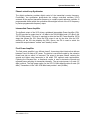
1.4.2 System Overview
The NX64A Digital Radio Link is a full duplex digital radio modem. It has a built-in
baseband modem, interface stage, an RF pre-amplifier, and an RF amplifier. No
external modems are required. Each radio requires a duplexer and an antenna. Refer to
Figure 1-1 for a typical block diagram.
NX64A radios are characterized by superior spectral efficiency. This efficiency is
achieved by using state of the art 7-level partial response modulation technique. High
spectral efficiency allows this family of radios to deliver the maximum utilization of the
RF bandwidth.
Since the use of the radio spectrum is highly regulated and limited in availability, it is
often very difficult, if not impossible, to get licensed for a large channel capacity.
Consequently, the smaller the channel capacity required by the radio, the greater are
the chances for obtaining a license.
NX64A
602-11060-11 R: C
1-14
System Characteristics
Figure 1-1
System Overview Diagram
NX64A
602-11060-11 R: C
System Characteristics
1-15
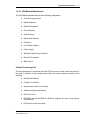
1.4.3 Module Subsystem Description
The NX64A Digital Radio Link is configured as a full duplex system. The basic
architecture for each of the radios is identical. This description applies to the entire
NX64A family of radios. Where applicable, this section will detail the differences
between models.
Each radio includes the following:
•
CPU/Modem Motherboard
•
Transmitter Module
•
Receiver Module
•
Front Panel
•
Power Supply
•
Data Interface Card
•
Duplexer
•
Digital Multiplexer Module (option)
•
Remote I/O (option)
•
G.703 module (option)
•
Forward Error Correction (option)
NX64A
602-11060-11 R: C
1-16
System Characteristics
Figure 1-2
System Block Diagram
NX64A
602-11060-11 R: C
System Characteristics
1-17
1.4.3.1 CPU/Modem Motherboard
The CPU/Modem Motherboard provides following subsystems:
•
Central Processing Unit
•
Digital Modulator
•
Digital Demodulator
•
Clock Recovery
•
Data Recovery
•
Digital Data Interface
•
Orderwire
•
Front Panel Interface
•
Power Supply
•
Standby/Transfer Panel Interface
•
Remote I/O Interface
•
NMS Control
Central Processing Unit
The microprocessor in conjunction with the FPGA logic acts as the central controller for
the radio. In addition to the microprocessor itself, the central controller consists of the
following:
•
Reset/Power Monitor
•
Parallel I/O controller
•
Asynchronous serial I/O controller
•
Address decoding and latching
•
Real Time Clock
•
•
EEPROM, Nonvolatile RAM and ROM for program and user setup memory
requirements
LED drivers for the front panel
NX64A
602-11060-11 R: C
1-18
System Characteristics
Digital Modulator
The digital modulator consists of scrambler, precoder, and partial response filter. The
modulator converts the incoming data into a shaped multilevel spectrally efficient signal,
using seven level partial response filtering. The scrambler prevents creation of discrete
spectral components. The precoder prevents the propagating of errors in the detection
of the data at the receiver/demodulator. The shaping filter produces the multilevel signal
and simultaneously band-limits its spectrum. A novel technique is used to implement the
precoder and the shaping filter in the digital domain. A D/A converter is used to generate
the signal that will FM modulate the transmitter.
Digital Demodulator
The digital demodulator consists of an active lowpass filter, an A/D converter, and a
multilevel bit slicer. The timing of the A/D and the slicing is determined by the recovered
clock. The noise filter limits the noise bandwidth. The A/D and the bit slicer recreates the
precoded signal sent by the digital modulator.
Clock Recovery
The clock is recovered from the signal after the noise filters. A PLL recovers the timing
information.
Data Recovery
The original serial data is recovered by passing the output of the slicer through a
“reverse precoder” and a descrambler. Error detection logic captures coding violations
and triggers the BER counter.
Digital Data Interface
The digital data interface can be V.35, RS-449, RS-232, EIA-530, or G.703.
Orderwire (Option)
An RJ45 connector provides access to the orderwire channel. Transformer-coupled TX
and RX ports allow for 2-wire or 4-wire operation. Interface levels are -16 dBm for the
inputs and +7 dBm for the output. The orderwire can FM modulate the radio as a
subcarrier, and can operate in lieu of the data.
NX64A
602-11060-11 R: C
System Characteristics
1-19
Power Supply
The CPU/Modem power supply circuitry accepts +12 VDC input from the system power
supply and generates +5 and +12 VDC (analog and digital). The battery monitor warns
the system of low voltage at the input. The reset/power monitor protects the nonvolatile
RAM with a battery backup.
Standby/Transfer Panel Interface
Provides the necessary interface I/O lines and software control for transfer
panel/standby unit configurations. The transfer panel (TP64) is external to the NX64,
and proviides a redundant hot or cold standby connection to another NX64 unit (see
Section 2.5 for more information on setups and settings).
Remote I/O Interface (Option)
Provides the necessary interface I/O lines and software control for the Remote I/O
option card that installs into connector P41.
NMS Control (Option)
The Network Management System (NMS) option is supported through microprocessor
software control.
NX64A
602-11060-11 R: C
1-20
System Characteristics
1.4.3.2 Transmitter Module
The transmitter module is mounted on a heat sink located on the rear of the radio
chassis. The transmit module receives the baseband modulated signal and mixes it to
achieve the desired center frequency. This modulated carrier is then amplified and sent
to the duplexer for transmission. Please refer to the block diagram in Figure 1-3.
The transmit module contains the following subsystems:
•
Voltage Controlled Oscillator
•
Phase-Locked Loop Synthesizer
•
Intermediate Power Amplifier
•
Final Power Amplifier
Figure 1-3
Transmitter Block Diagram
Voltage Controlled Oscillator
The voltage controlled oscillator (VCO) is a variable frequency source operating in either
the 790-960 MHz band or the 297-512 MHz band. It uses a 1/4 wavelength coaxial
resonator configuration for low noise operation. The resonator length determines the
general operating frequency of the VCO and is chosen for operation within required
frequency bands. Two hyperabrupt variable capacitance diodes (varactors) provide
independent and optimized control over the center frequency and modulation (FM)
sensitivity. The output of the VCO is buffered by a wideband amplifier that provides an
output level of +8 dBm.
NX64A
602-11060-11 R: C
System Characteristics
1-21
Phase-Locked Loop Synthesizer
The digital synthesizer provides digital control of the transmitter's center frequency.
Functionally, the synthesizer phase-locks the voltage controlled oscillator (VCO)
centered at the required transmitter frequency to a stable crystal reference oscillator. A
programmable divider within the synthesizer allows digital control of the VCO frequency
in precise programmable frequency steps.
Intermediate Power Amplifier
The buffered output of the VCO drives a wideband Intermediate Power Amplifier (IPA).
The IPA provides an output level of +16 dBm in the 790-960 MHz band (+21 dBm in the
297-512 MHz band). This level is required to drive the final RF Power Amplifier (RFA)
stage that follows the IPA. Since the RFA output is set by the drive from the IPA,
switching off the IPA also disables the RFA. Hence, the IPA is used to switch the
transmitter output between "radiate" and "standby" modes.
Final Power Amplifier
The final power amplifier is an efficient class-C, three-stage hybrid device that delivers
between 6 and 10 watts of RF power. The device is convection cooled by the extrusion
finned heat sink on which it is mounted. The output is low-pass filtered, reducing the
second and higher order harmonics to fall within FCC spectral mask requirements.
Following the low-pass filter, a directional coupler is used to determine forward and
reflected power sampling for transmitter telemetry. The net output power is 5 watts (37
dBm) nominal. The high power option for the 297-512 MHz band provides 9 watts (40
dBm). Transmitters in the 1425-1535 MHz band provide 1 watt (30 dBm).
NX64A
602-11060-11 R: C
1-22
System Characteristics
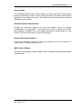
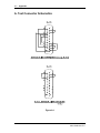
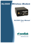
1.4.3.3 Digital Receiver Module
The Moseley Digital Receiver Down Converter Module consists of two cards:
i. RF Down Converter for 300-512MHz, 790-960MHz, and 1350-1525MHz to
70MHz.
ii. Digital Down Converter and Demodulator that takes a 70MHz signal from the RF
card and down reverb filters (?) and FM demodulates the received carrier.
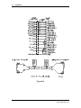
RF Down Converter
ALC
Loop Amp
ALC Control
RF AGC
ALC
Det
RF Input
IF Output
BPF
Diplexer
BPF
70 MHz
70 MHz
70 MHz
Atten
Preamp
to QAM
Demod
IF Amp
Synth Level
Synth Lock
Synth Data
Loop
Filter
VCO
Synth
Clk
Synth
Enbl
uP
Data
Clk
PLL
PLL
Enbl
Ref
Synth
10MHz
TCXO
Lock
Figure 1-4
RF Down Converter Block Diagram
The receiver handles the traditional RF to IF conversion from the carrier to 70 MHz (see
Figure 1-4, above). Considerations are given to image rejection, inter-modulation
performance, dynamic range, agility, and survivability. A separate AGC loop was
assigned to the RF front end to prevent inter-modulation and saturation problems
associated with reception of high level undesirable interference from RF signals
resulting from RF bandwidth that is much wider than the IF bandwidth. These problems
are tyupically related to difficult radio interference environments that include high power
pagers, cellular phone sites, and vehicle location systems.
NX64A
602-11060-11 R: C
System Characteristics
1-23
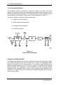
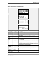
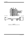
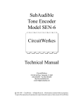
Digital Down Converter
The Digital Down Converter accepts a signal from the RF board at 70 MHz and delivers
a baseband output to the CPU modem with RSSI indication. The Digital Down
Converter consists of the following:
i. Input 70 MHz SAW Filter with a 50 dB bandwidth of 1 MHz.
ii. A 80 dB AGC amplifier attenuator assembly that provides 20 DB of attenuation
or up to 60 dB of gain.
iii. A 14 bit high sample rate A/D converter sampled at 16 MHz.
iv. A programmable digital down converter assembly that accepts the sub-sample at
its IF input and demodulates the RM carrier.
v. D/As for baseband, AGC control and RSSI purposes.
vi. Microprocessor for status control and configuration purposes.
From
RF Board
Saw
Filter
AGC
AGC
Auto
Manual
14 bit
A/D
Moseley
Programmable
Digital Down
Converter
D/A
D/A
Bareband
D/A
RSSI
IF Filter Status
Processor
IF Filter Select
Figure 1-5
Digital Down Converter Block Diagram
The down converter accepts input from the CPU modem to select either a 25, 50, 100,
200 or 400 MHz filter within the down converter chip. This eliminates the need for
external analog crystal filters. Each radio can now be run with any of the IF filters. All
CPU function menus remain the same as for the older analog filter radios.
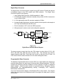
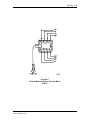
Programmable Down Converter
The Moseley Programmable Down Converter (PDC) is an agile digital tuner designed to
meet the requirements of a wide variety of communication industry standards. The PDC
contains the processing functions needed to convert sampled IF signals to baseband
digital samples. These functions include LO generation/mixing, decimation filtering,
programmable FIR shaping/bandlimiting filtering, re-sampling, AGC, frequency
discrimination and detection.
A top level functional block diagram of the Moseley PDC is shown below. This diagram
shows the major blocks and multiplexers used to reconfigure the data path for various
architectures.
NX64A
602-11060-11 R: C
1-24
System Characteristics
Figure 1-6
Functional Block Diagram of the Moseley Programmable Down Converter
The Moseley PDC consists of 13 different sections: Synchronization, Input, Input Level
Detector, Carrier Mixer/Numerically Control Oscillator (NCO), CIC Decimating Filter,
255-Tap Programmable FIR Filter, Automatic Gain Control (AGC), Re-sampler/Halfband
Filter, Timing NCO, Cartesian to Polar Converter, Discriminator and Output Sections.
All of these sections are configured through a microprocessor interface.
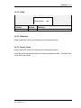
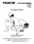
Automatic MSB Adjust Circuit
The AUTO MSB board is an assembly that replaces the manual MSB adjustment
circuitry on the NX64 CPU/MODEM board. A block diagram is shown below in Figure 17.
Input
Signal
A/MS
∫
LPF
Σ
A/D Input
DC volts,
A/D Input
Centered
Figure 1-7
MSB Adjustment Circuitry
NX64A
602-11060-11 R: C
System Characteristics
1-25
The circuit consists of an integrator, a low-pass filter, and a summing amplifier that
performs the MSB adjusting function automatically. The MSB adjust potentiometer
“A/DREF” (R1213) on the CPU/MODEM board becomes inoperative.
Install the AUTO MSB Board
To install the AUTO MSB Board:
1. Unplug the power into the NX64.
2. Remove the top cover.
3. Locate and carefully remove U121 from the CPU/MODEM board, taking care
not to bend the IC pins.
4. Install the IC onto the AUTO MSB board; be sure to align pin 1 correctly.
5. Install the AUTO MSB board at location U121.
6. Using a small soldering iron, solder the free end of the purple wire to P120 pin
11.
7. Replace the top cover.
8. Apply power to the NX64.
No other adjustments should be required.
NX64A
602-11060-11 R: C
1-26
System Characteristics
1.4.3.4 Front Panel
The radio is provided with an intelligent front panel. This front panel includes:
•
An 80 character (4X20) LCD display module.
•
Six switches for configuration and testing.
•
Seven LEDs for critical status display.
The LCD module is menu-driven and provides a very easy user interface for
configuration setting and testing. In addition, it displays status and events. The transmit
and receive frequencies can be set up via the front panel. The front panel allows the
control and configuration of the local as well as the remote radio. Refer to the Operation
Section (Section 3) for more information.
1.4.3.5 Power Supply Module
The radio is powered with a modular power supply. Modules are available for universal
AC (90 - 260 VAC, 47 - 63 Hz) and DC (±12, ±24, or ±48 VDC). These modules are all
able to supply the necessary power for a full configuration of the NX64A Radio. Jumpers
on the circuit board allow the power supply ground to be common with the chassis
ground or isolated (for negative DC inputs). The power supply provides +12 VDC to the
CPU/Modem, which generates and distributes the various system voltages.
1.4.3.6 Data Interface Cards
The data interface cards, or digital drivers, provide level translation compatibility for
various industry standards. Currently, the supported standards are V.35, RS-449,
RS-232, EIA-530, and V.36/G.703 (for 64 / 128 kbps only). The SL9000DM Digital
Multiplexer option supports V.35, RS-449, RS-232, and Voice/Telco.
Two types of data interface cards are used by the NX64A. One plugs into the
CPU/Modem, providing the digital interface for the composite I/O. The other type of
driver cards are used with the SL9000DM Digital Multiplexer option, to interface with the
data channels. Each channel uses a separate interface card. An additional card
establishes the trunk interface.
The appropriate cables are provided which configure the NX64A as a DCE. Gender
mismatches may occur if equipment manufacturers interpret the standards differently.
Contact customer service in this event.
NX64A
602-11060-11 R: C
System Characteristics
1-27
1.4.3.7 Duplexers
In full duplex radios with a common antenna, a duplexer provides the necessary
isolation between transmit and receive frequencies. Duplexers supplied with NX64A
radios provide at least 65 dB isolation.
The duplexer used with the NX64A is a three-port filter device that separates TX and RX
carrier signals and routes them to the appropriate system modules. The duplexer is a
combination high-pass and low-pass pair. The response is optimized for low insertion
loss (at the pass frequency) and maximum attenuation (at the reject frequency). The
insertion loss directly affects power out (on the TX side) and sensitivity (on the RX side).
The device consists of multiple high-Q, capacitively-tuned TEM cavity resonators. The
result is at least 65 dB isolation between the transmit and receive frequencies.
The selection of a duplexer depends on a number of factors, including frequency of
operation, separation between these frequencies, minimum required TX/RX isolation,
and power level. The NX64A offers a number of duplexer choices. Depending on the
physical configuration and size of a duplexer, it can be mounted either inside the NX64A
chassis or externally, in a rack.
In the 297-512 MHz band, if the separation is 4.5 MHz or greater, an internal duplexer
may be used. If the separation is less than 4.5 MHz, an external duplexer must be used.
In the 790-960 MHz band, if the separation is 9.0 MHz or greater, the duplexer can be
mounted inside. If the separation is less than 9.0 MHz, an external duplexer must be
used.
1.4.3.8 Digital Multiplexer Module (Option)
The NX64A has card slots allowing the use of up to two SL9000DM Digital Multiplexer
modules. The SL9000DM replaces external multiplexer equipment. Each module
provides 4 data channels (8 channels with two modules). Each channel is independently
configured using a plug-in data interface “daughter card” that determines the
communications standard for that channel. Multiplexer interface cards are available for
V.35, RS-449, RS-232, and Voice/Telco. In addition, the trunk connection (between the
multiplexer and the Communications I/O connector to the CPU/Modem) requires an
interface card on the SL9000DM and a matching card on the CPU/Modem.
Set up of the SL9000DM is accomplished through a set up port, using an external
computer.
The SL9000DM requires the presence of the backplane at the rear of the card cage to
provide power supply connections and bus interconnection between the multiplexer
cards.
Detailed information about the SL9000DM is available in a separate manual.
NX64A
602-11060-11 R: C
1-28
System Characteristics
1.4.3.9 Remote I/O (Option)
The Remote I/O option provides remote control functions. The card supplies six relayisolated control outputs, four optically-isolated status (digital) inputs, and four singleended analog inputs. The back panel connectors “External Output” and “External Input”
are located on this board.
Contact Moseley Associates for more information about the Remote I/O option.
1.4.3.10 Remote Metering (Option)
The Remote Metering option allows the user to access the front panel LED status levels
through the rear panel “ORDERWIRE” jack of the NX64A. These logic levels can be
monitored by a remote control system such as the Moseley MRC-1620LP or MRC-2.
Contact Moseley Associates for more information about the Remote Metering option.
1.4.3.11 FEC—Forward Error Correction (Option)
To overcome industrial and other man-made impulse noise as well as other burst-mode
interferences, powerful Reed-Solomon Forward Error Correction is available as an
option. Unfaded BER performance in excess of 10-11 offers unparalleled error-free
performance.
Contact Moseley Associates for more information about the Remote Metering option.
NX64A
602-11060-11 R: C
Section 2
Installation
Section
Contents
Page
2.1
2.2
2.3
2.3.1
2.3.2
2.3.2.1
2.3.2.2
2.4
2.4.1
2.4.2
2.4.3
2.4.4
2.5
2.5.1
2.5.2
2.5.3
2.5.3.1
2.5.3.2
2.5.4
2.5.4.1
2.5.4.2
2.5.5
2.5.6
2.5.6.1
2.5.6.2
2.5.7
2.5.8
2.5.8.1
2.5.8.2
Introduction
Unpacking/Inspection/Inventory
Pre-Installation Testing
Warnings
Loopback Tests
Local Loopback Testing
Remote Loopback (End-to-End) Testing
Interconnection to Other Equipment
Timing
Repeater Connections
NX64A to SDM-T (ACT)
NX64A to Kilomux (RAD)
Standby Configuration
Rack Installation
Power Supply
Equipment Interconnection-NX64A
External Duplexer (*preferred)
Internal Duplexer
Hot/Cold Standby Modes
Hot Standby (*preferred)
Cold Standby
NX64 Receiver Operation
TP64 Front Panel Controls and Indicators
LED Indicators
TRANSFER Switches
Master/Slave Operation & LED Status
Software Settings
NX64A Clock Settings
NX64A Control Settings
2-3
2-3
2-5
2-7
2-8
2-9
2-11
2-13
2-13
2-21
2-23
2-25
2-27
2-27
2-27
2-28
2-28
2-29
2-30
2-30
2-30
2-30
2-30
2-31
2-31
2-31
2-33
2-33
2-33
Continued on following page...
NX64A
602-11060-21 R: C
2-2
Installation
Section
Contents (continued)
Page
2.6
2.6.1
2.6.2
2.6.3
2.6.4
2.6.5
2.7
2.7.1
2.7.2
2.7.3
2.7.4
2.8
Site Installation
Physical and Environmental Considerations
Power Requirements
RF Connections
Data Connections
Rack Mount Installation
Antenna/Feed System
Antenna Installation
Transmission Line Installation
Testing
Environmental Seals
Link Alignment
2-34
2-35
2-36
2-36
2-36
2-37
2-38
2-38
2-38
2-39
2-40
2-41
NX64A
602-11060-21 R: C
Installation
2-3
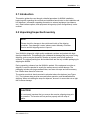
2.1 Introduction
This section guides the user through a detailed procedure for NX64A installation,
beginning with unpacking the unit and pre-installation bench tests, to site installation and
link alignment. Information regarding connection to external equipment (mux/demux,
etc.), data interface options, and equipment timing setup (clock configurations) is also
covered.
2.2 Unpacking/Inspection/Inventory
NOTE
Please check for damage to the outside and inside of the shipping
container. If any damage is noted, please contact Moseley Customer
Service and the shipping carrier to report it.
Your NX64A is shipped in a high-quality cardboard container and packed with highdensity molded foam. This packaging can withstand the damage that may occur during
shipping, such as may be caused by vibration or impacts, and will still protect its
contents. The original packing box and molded foam are the only suitable packaging for
shipping the NX64A.
During unpacking, observe how the NX64A is packed. If the equipment must be reshipped, it must be repacked in exactly the same manner to avoid damage. The
packaging includes one large cardboard box, two foam side caps and one accessory
box. Retain these items for future use.
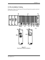
The receiver module is shock-mounted to a bracket above the duplexer (see Figure
2-1). The tie-down strap must be removed before operation, and reinstalled before
shipping. When re-installing the strap for shipment, be sure it is secure but not so tight
that it causes damage.
CAUTION
It is extremely important that you remove the receiver shipping strap prior
to operation. The receiver will not perform properly with the strap in
place.
NX64A
602-11060-21 R: C
2-4
Installation
Take inventory of the complete package to ensure that all necessary parts are present.
A quick review of your pre-installation site survey form, purchase order, and shipping list
should reveal any discrepancies.
Figure 2-1
Shipping Strap Removal
NX64A
602-11060-21 R: C
Installation
2-5
2.3 Pre-Installation Testing
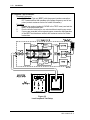
Please refer to Figure 2-2 (Rear Panel I/O Ports and Controls) for a general overview of
the NX64A connector panel.
Figure 2-2
Rear Panel I/O Ports and Controls
NX64A
602-11060-21 R: C
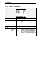
2-6
Installation
[1]
[2]
TRANSMITTER HEAT SINK
TRANSMITTER POWER OUTPUT: Internal duplexer: not required. External
duplexer: type N; 5 watts nominal; antenna connection or RF dummy load required
at all times.
RECEIVER INPUT OR DUPLEXER ANTENNA PORT: Internal duplexer: duplexer
antenna port; type N; combined transmitter and receiver; antenna connection or
RF dummy load required at all times. External duplexer: receiver input port; type N;
10 mW (+10 dBm) maximum input level.
COMPOSITE DATA I/O PORT: (25 pin D-female) Primary data bit stream
input/output port; factory-configured for V.35, RS-449, RS-232, EIA-530, and
G.703 interfaces.
NETWORK MANAGEMENT SYSTEM I/O PORT: (9 pin D-male) NMS I/O option.
STANDBY/TRANSFER PANEL INTERCONNECT: (9 pin D-female) Connect to
TP64 transfer panel for standby unit interface.
EXTERNAL INPUT: (15 pin D-female) Remote I/O option card input status lines.
EXTERNAL OUTPUT: (37 pin D-female) Remote I/O option card output control
lines.
ORDER WIRE: (RJ45) Order wire I/O option/remote metering interface option.
CPU RESET BUTTON: Hard boot of system CPU.
CHASSIS GROUND CONNECTION: (Screw Terminal)
AC LINE INPUT: (IEC Standard) 90-260 VAC, 47-63 Hz, 45 watts minimum;
internal fuse (refer to the power supply module PC board legend for proper fuse
ratings).
+12V LED: Indicates main supply operation (green indicates normal operating
condition).
+5V LED: Reserved for other Moseley products.
DC INPUT: Input voltage as indicated on panel. All units are shipped with an
isolated ground input. An internal jumper is provided in the power supply module to
provide a common chassis connection (negative ground). This may be required to
solve system ground loop problems (only possible for positive DC supply
installations). Internal fuse: refer to the power supply module PC board legend for
proper fuse ratings.
[3]
[4]
[5]
[6]
[7]
[8]
[9]
[10]
[11]
[12]
[13]
[14]
[15]
NX64A
602-11060-21 R: C
Installation
2.3.1 Warnings
Before applying power to the NX64A please be aware of the following:
WARNING
RF radiation may be dangerous above certain exposure levels.
NEVER stand in front of the antenna when the transmitter is
radiating.
CAUTION
An antenna or dummy load MUST be connected to the transmitter if
power is applied to the unit and the transmitter is enabled. Failure to
observe this precaution can damage the power amplifier of the
transmitter.
DO NOT connect the transmitter power output (antenna port) to the
receiver input! This WILL destroy the receiver.
When a duplexer is used, DO NOT set the transmitter to a frequency
which is different than that marked on the duplexer. Failure to observe
this precaution can damage the power amplifier of the transmitter.
NX64A
602-11060-21 R: C
2-7
2-8
Installation
2.3.2 Loopback Tests
Loopback tests enable the user to easily determine the operational status of the NX64A.
There are two types of internal loopback modes (analog and digital), and two types of
external loopback modes (RF and hardwire). The diagrams in Figure 2-3 (Local
Loopback Test Setup) and Figure 2-4 (Remote Loopback Test Setup) provide a
conceptual block diagram of the loopback configurations. The front panel status
indicator marked LBK will illuminate during loopback tests.
Digital Loopback
Digital Loopback connects the digital input to the digital output of the NX64A. This
loopback is bilateral and also connects the digital output to the digital input for remote
loopback tests. The loopback connection is performed at the modem and is switched in
software (use the TEST menu screen, see section 3.4.4).
Analog Loopback
Analog Loopback connects the analog output of the modulator to the analog input of the
demodulator. The loopback connection is performed at the modem and is switched in
software (use the TEST menu screen, see section 3.4.4).
RF Loopback (external)
RF Loopback requires a “turnaround box” that translates the transmitter carrier
frequency to the frequency of the receiver at a much lower power level. This test will
check all the subsystems of the NX64A digital radio/modem.
Hardwire Loopback (external)
Hardwire Loopback utilizes a special connector at the Composite I/O port that loops the
data back into the NX64A unit. It is nearly identical to the internal digital loopback
(above), but this will test the data interface card in a remote loopback test.
NX64A
602-11060-21 R: C
Installation
2-9
2.3.2.1 Local Loopback Testing
Local Loopback testing is a simple method of verifying the performance of a single
NX64A unit. Refer to Figure 2-3 (Local Loopback Test Setup) for more information.
Digital Loopback can verify:
•
The data interface card is working properly.
•
The external mux equipment is communicating with the NX64A.
Analog Loopback can verify:
•
The NX64A modem is working properly.
RF Loopback can verify:
•
The entire system, including the transmitter and receiver modules, are
working properly.
Analog or Digital Loopback Test Procedure:
Required Equipment:
Bit Error Rate Test set (BERT) set with the proper interface connection.
RF power termination (10 Watt min, 50 ohms, “dummy load”).
Procedure:
1.
Place the modem into digital loopback (TEST menu) and set the BERT
to the proper data rate.
2.
Run the bit error rate test for one minute without receiving any errors.
3.
Repeat this test using analog loopback in the NX64A.
4.
After one minute no errors should be recorded.
5.
If errors are recorded in either of these tests and proper connection
and operation of the BERT test has been verified, call customer service
for further instructions.
NX64A
602-11060-21 R: C
2-10
Installation
RF Loopback Test Procedure:
Required Equipment:
Bit Error Rate Test set (BERT) with the proper interface connection.
RF Turnaround Box that operates at the proper frequency and is lownoise (contact customer service for further information).
Procedure:
1.
Disable the modem loopback (CLEAR in the TEST menu) and set the
BERT to the proper data rate.
2.
Run the bit error rate test for one minute without receiving any errors.
3.
If errors are recorded in this test and proper connection and operation
of the BERT test has been verified, call customer service for further
instructions.
Figure 2-3
Local Loopback Test Setup
NX64A
602-11060-21 R: C
Installation
2-11
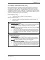
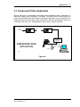
2.3.2.2 Remote Loopback (End-to-End) Testing
Remote Loopback testing is a method of verifying the performance of a link (two or
more units). In this test, the remote radio performs the loopback function, therefore
returning data through to the local unit. Proper operation of the local unit should be
verified prior to performing this test. These tests can be performed on the bench before
installation (End-to-End), or across an actual RF link after installation. Refer to Figure 24 (Remote Loopback Test Setup) for more information.
Digital Loopback can verify:
•
The remote RF portion of the link is working properly.
Hardwire Loopback can verify:
•
The entire system, including the transmitter and receiver modules, are
working properly.
Digital Loopback Test Procedure:
Required Equipment:
Bit Error Rate Test set (BERT) set with the proper interface connection.
RF power termination (10 Watt min, 50 ohms, “dummy load”).
Procedure:
1.
Place the modem into digital loopback (TEST menu) and set the BERT
to the proper data rate.
2.
Run the bit error rate test for one minute without receiving any errors.
3.
If errors are recorded in this test and proper connection and operation
of the BERT test has been verified, call customer service for further
instructions.
RF Loopback Test Procedure:
Required Equipment:
Bit Error Rate Test set (BERT) with the proper interface connection.
RF Turnaround Box that operates at the proper frequency and is lownoise (contact customer service for further information).
Procedure:
1.
Disable the modem loopback (CLEAR in the TEST menu) and set the
BERT to the proper data rate.
2.
Run the bit error rate test for one minute without receiving any errors.
3.
If errors are recorded in this test and proper connection and operation
of the BERT test has been verified, call customer service for further
instructions.
NX64A
602-11060-21 R: C
2-12
Installation
Figure 2-4
Remote Loopback Test Setup
NX64A
602-11060-21 R: C
Installation
2-13
2.4 Interconnection to Other Equipment
This section describes typical interconnections to some external equipment that has
been tested and verified. Be careful to note that other manufacturer’s equipment may be
different than what is referenced here, therefore please refer to all applicable operating
manuals for current configurations.
2.4.1 Timing
Incorrect timing and clock settings are the most common causes of all system problems
concerning non-synchronization of data and clock contention. It is most important to
understand the system requirements and to be able to resolve timing conflicts when
dealing with equipment from different manufacturers. Some familiarity with industry
terminology is helpful when confronted with timing problems.
All of the equipment should be synchronized to the same timing source. Otherwise, data
errors can occur. The user must determine which unit will provide the system clock.
When interconnecting and synchronizing various pieces of equipment, it is often helpful
to ask two simple questions:
Which piece of equipment is supplying the clock?
Which piece of equipment is receiving the clock?
NX64A
602-11060-21 R: C
2-14
Installation
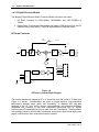
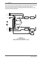
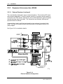
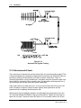
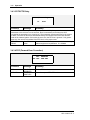
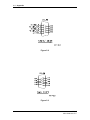
Figure 2-5 below shows a conceptual diagram of the NX64A modem internal data/clock
timing. The external Composite I/O connections are on the left. Note that the
demodulator is always synchronized to the recovered data. The RX CLK source only
affects the output data synchronizer.
TX DATA IN
TX CLOCK OUT
(TERMINAL TIMING)
A
ANTENNA
B
INTERNAL
OSCILLATOR
TX CLOCK IN
(SEND TIMING)
C
TO/FROM
Q
D
MUX
MUX
TX CLOCK
SOURCE
RISING/
FALLING
EDGE
FEC
INPUT DATA
MODULATOR/
SYNCHRONIZER
TRANSMITTER
FRONT
PANEL
OR
RX CLOCK
SOURCE
RISING/
FALLING
EDGE
MUX
MUX
SELECTIONS
COMPOSITE
I/O
ANTENNA
RX CLOCK IN
D
OUTPUT DATA
RX CLOCK OUT
(RECEIVE TIMING)
RX DATA OUT
E
SYNCHRONIZER
Q
D
RECEIVER/
DEMODULATOR
F
RECOVERED CLOCK
CLOCK
RECOVERY
(MD1188-B)
Figure 2-5
Conceptual Diagram
NX64A Modem Internal Data/Clock Timing
NX64A
602-11060-21 R: C
Installation
2-15
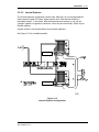
Figure 2-6 below shows a conceptual diagram of the NX64A FEC internal data/clock
timing. Note that when the FEC option is installed in the unit, the Composite I/Os
labeled A through F in Figure 2-5 are connected to FEC board as shown in Figure 2-6.
FEC
EN / DISABLE
TX DATA IN
A
TX DATA
TO MODEM
TX CLOCK OUT
(TERMINAL TIMING)
B
TX CLOCK
FROM MODEM
TX CLOCK IN
(SEND TIMING)
C
TX CLOCK
TO MODEM
FEC
TX CLOCK
TO/FROM
COMPOSITE
FEC
ENGINE
I/O
TO/FROM
MODEM,
FEC
RX CLOCK
RX CLOCK IN
FEC BOARD
SW 7
D
RX CLOCK
TO MODEM
RX CLOCK OUT
(RECEIVE TIMING)
E
RX CLOCK
FROM MODEM
RX DATA OUT
F
RX DATA
FROM MODEM
N.C.
FEC
EN / DISABLE
(MD1188-C)
Figure 2-6
Conceptual Diagram
NX64A FEC Internal Data/Clock Timing
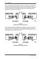
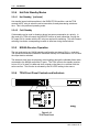
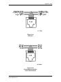
Figure 2-7 below shows a situation where the local NX64A is supplying the master clock
for the whole system. The local and remote data terminal equipment (DTE) should both
be configured to accept clocks from their respective NX64A.
Figure 2-7
NX64A Data/Clock Timing. Example 1.
NX64A
602-11060-21 R: C
2-16
Installation
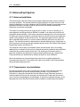
Figure 2-8 below depicts the local DTE as the “master” clock source. The local DTE can
derive its clock internally, or alternately can derive its clock from connected sources or
network timing. The local DTE supplies the transmit clock to the NX64A. In this diagram,
the remote DTE should be set to accept the transmit clock from the NX64A and to
supply (echo) a receive clock to the NX64A.
Figure 2-8
NX64A Data/Clock Timing. Example 2.
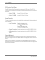
Figure 2-9 below illustrates some alternate clock connections when the local DTE is the
"master" clock source. The local DTE should be configured to supply both a transmit
clock and a receive clock to the NX64A. The remote DTE must be configured to accept
either a transmit clock, a receive clock, or both.
Figure 2-9
NX64A Data/Clock Timing. Example 3.
NX64A
602-11060-21 R: C
Installation
2-17
Figure 2-10 portrays a repeater configuration. In this situation, two NX64As are
connected "back-to-back" to repeat the RF data. The NX64As are connected to each
other via their COMPOSITE I/O with a "null modem" cable.
Figure 2-10
NX64A Data/Clock Timing. Example 4.
The previous examples do not represent every possible system configuration, but are
intended to give the user enough information to be able to configure the system.
The NX64A requires definition of the source for the transmitter clock (TX CLK) and the
receiver clock (RX CLK).
NX64A
602-11060-21 R: C
2-18
Installation
Transmitter Clock Source Options (TX CLK)
•
Internal Oscillator
The transmitter modem clock is synchronized to the
NX64A internal system clock. In this case, the NX64A
is now supplying the system clock to all connected
components.
•
External TX Clock
The transmitter modem clock is synchronized to an
externally generated clock, usually an external MUX
that is interfacing to the NX64A. In this case, the
NX64A is now receiving the system clock.
•
Recovered Clock
The clock is derived from the demodulated incoming
bit stream in the receiver. A remote link will normally
be set in this mode, as the remote receiver is deriving
the system clock from the local NX64A transmitter via
its incoming data.
•
External RX Clock
The transmitter is synchronized to an external source
supplied to the receiver, usually the external MUX that
is interfacing to the remote NX64A. (Same as
external Tx Clock when FEC is installed.)
Transmitter Clock Phase
TX CLOCK must be configured for the proper clock phase (RISING EDGE or FALLING
EDGE). This choice appears with the clock source, with no separate menu heading.
•
RISING EDGE
The radio/modem samples input data on the rising
edge of the clock waveform. This is the normal
setting. (Required for FEC enabled.)
•
FALLING EDGE
The radio/modem samples input data on the falling
edge of the clock waveform.
NX64A
602-11060-21 R: C
Installation
2-19
Receiver Clock Source Options (RX CLK)
•
Internal Oscillator
The receiver output clock is synchronized to the
NX64A internal system clock.
•
External TX Clock
The receiver output clock is synchronized to an
externally generated clock supplied to the transmitter,
usually the external MUX that is interfacing to the
NX64A.
•
Recovered Clock
The receiver output clock is derived from the
demodulated incoming bit stream in the receiver. All
receivers in the link will normally be set in this mode.
•
External RX Clock
The receiver output clock is synchronized to an
external source supplied to the receiver, usually the
external MUX that is interfacing to the NX64A.
(Same as external TX clock when FEC is installed.)
Note
The modem receiver clock is always synchronized to
the Recovered Clock.
Receiver Clock Phase
RX CLOCK must be configured for the proper clock phase (RISING EDGE or FALLING
EDGE). This choice appears with the clock source, with no separate menu heading.
•
RISING EDGE
The radio/modem output data changes state on the
rising edge of the clock waveform.
•
FALLING EDGE
The radio/modem output data changes state on the
falling edge of the clock waveform. This is the normal
setting. (Required for FEC enabled.)
NX64A
602-11060-21 R: C
2-20
Installation
FEC Receiver Clock Phase
The FEC Receiver Clock Phase switch is located on the FEC board. The FEC RX
CLOCK must be configured for the proper clock phase as determined by the connected
equipment.
•
Switch 7 OPEN
Normal RX Clock Out Phase.
•
Switch 7 CLOSED
Inverted RX Clock Out Phase.
Normal Operation
The issue of setting the clocks can be simplified by considering the following settings for
normal operation:
•
Local Transmitter
•
Remote Transmitter Normally synchronized to the RECOVERED CLOCK
•
All Receivers in the Normally synchronized to the RECOVERED CLOCK.
chain
Supplies the system clock
(TX CLK = INTERNAL OSC)
<or>
Receives the system clock
(TX CLK = EXTERNAL TXC)
External Equipment
When the local transmitter is receiving the system clock, the external equipment must
be set up to supply the clock to the NX64A. Refer to the appropriate owner's manual for
details.
When the remote NX64A is synchronized to the RECOVERED CLOCK, the external
equipment must be set up to receive the clock from the NX64A. Refer to the appropriate
owners manual for details.
NX64A
602-11060-21 R: C
Installation
2-21
2.4.2 Repeater Connections
The NX64A can be used as a digital repeater. The typical clock and configuration
settings for the equipment are detailed in Table 2-1. The digital connections are shown
in Figure 2-11.
Table 2-1
NX64A Repeater Clock Settings
NX64A
602-11060-21 R: C
Parameter
Setting
TX CLK
External TXC
Rising Edge
RX CLK
Recovered CLK
Rising Edge
2-22
Installation
Figure 2-11
NX64A Repeater Interconnection
NX64A
602-11060-21 R: C
Installation
2-23
2.4.3 NX64A to SDM-T (ACT)
Interconnection of the NX64A with the SDM-T MUX, manufactured by ACT (Advanced
Compression Technologies), is detailed in this section. Figure 2-12 shows a typical
interconnection (V.35 or RS-449). The cable schematic can be found in the Appendix.
The typical clock and configuration settings for the equipment are detailed in Tables 2-2
(NX64A Source) and 2-3 (SDM-T Source).
Figure 2-12
NX64A Interconnection to SDM-T
NX64A
602-11060-21 R: C
2-24
Installation
Table 2-2
Clock Settings - NX64A to SDM-T (NX64A Source)
SOURCE CLOCK = NX64A
SDM-T:
SYSTEM:
LINK:
SDR-XX:
(NX64A)
PARAMETER
“Master”
“Slaves”
Local Unit
Slave Lock
Super B/W
Vcross
Auto Reset
Loc Ring
Rem Ring
C Code
HS-DBA
System Timing Source
Primary
Fallback
Clock
Rate
AutoBaud
Framing
Sat Hop Count
MASTER
xxx
xxx
xxx
OFF
xxx
xxx
xxx
xxx
SLAVE
xxx
xxx
xxx
OFF
xxx
xxx
xxx
xxx
LINK TXC
--EXTERNAL
xxx
OFF
xxx
1
LINK TXC
--EXTERNAL
xxx
OFF
xxx
1
Tx Clk
INTERNAL OSC
RISING EDGE
RECOV CLK
FALLING EDGE*
RECOV CLK
RISING EDGE
RECOV CLK
FALLING EDGE*
Rx Clk
note: xxx = don’t care
* 384 kbps: set to RISING EDGE
Table 2-3
Clock Settings - NX64A to SDM-T (SDM-T Source)
SOURCE CLOCK = SDM-T
SDM-T:
SYSTEM:
LINK:
SDR-XX:
(NX64A)
PARAMETER
“Master”
“Slaves”
Local Unit
Slave Lock
Super B/W
Vcross
Auto Reset
Loc Ring
Rem Ring
C Code
HS-DBA
System Timing Source
Primary
Fallback
Clock
Rate
AutoBaud
Framing
Sat Hop Count
MASTER
xxx
xxx
xxx
OFF
xxx
xxx
xxx
xxx
SLAVE
xxx
xxx
xxx
OFF
xxx
xxx
xxx
xxx
LINK TXC
--INTERNAL
xxx
OFF
xxx
1
LINK TXC
--EXTERNAL
xxx
OFF
xxx
1
Tx Clk
EXTERNAL TXC
RISING EDGE
RECOV CLK
FALLING EDGE*
RECOV CLK
RISING EDGE
RECOV CLK
FALLING EDGE*
Rx Clk
note: xxx = don’t care
* 384 kbps: set to RISING EDGE
NX64A
602-11060-21 R: C
Installation
2-25
2.4.4 NX64A to Kilomux (RAD)
The NX64A interconnection with the Kilomux, manufactured by RAD Technologies, is
detailed in this section. Figure 2-13 shows a typical interconnection (V.35). The cable
schematic can be found in the Appendix.
The typical clock and configuration settings for the equipment are detailed in Table 2-4.
Moseley does not recommend using the Kilomux as the clock source.
Figure 2-13
NX64A Interconnection to RAD Kilomux
NX64A
602-11060-21 R: C
2-26
Installation
Table 2-4
Clock Settings - NX64A to Kilomux
SOURCE CLOCK = NX64A
PARAMETER
RAD KILOMUX:
SYSTEM PARAMETER:
SETTING
DWLD_BW
ML_MODE
ACTIVE_ML
NO
SINGLE
AUTO
TEST OPTION ML:
REMOTE LOOP
OFF
LINK PARAMETER:
SPEED
TIMING
BUFFER SIZE
PSR & CTS
(same data rate as
NX64A)
DTE
8
INT
SPEED
DATA
PARITY
INTERFACE
MANAGEMENT
AUTO
8
NO
DCE
NO
Tx Clk
INTERNAL OSC
RISING EDGE
RECOVERED
FALLING EDGE
SP PARAMETERS:
NX64A:
CONFIGURATION
(CLOCK SOURCE):
Rx Clk
NX64A
602-11060-21 R: C
Installation
2-27
2.5 Standby Configuration-TP64
New Installation:
Normally, the TP64 is shipped with the Main and Standby radios per the customer order,
and all of the settings are factory set for the system.
The external duplexer (external to the NX64A radio) will be mounted to the rear of the
TP64 chassis and the appropriate frequencies will be marked for quick identification.
If using an internal duplexer (internal to the NX64A radio), it is probably a retrofit or
temporary situation. See Section 2.3.1 for details.
The shielded ribbon Y-cable is included for making the data I/O connections to the
radios.
Main/Standby Retrofit:
If the TP64 is to be installed in an existing site to convert a standalone unit to a
main/standby, particular attention must be made to set up all of the parameters as
discussed in this manual.
For an NX64A application, it may be more expeditious to send the units to Moseley for
setup. Duplexer tuning (if required) must be carefully performed for optimum link
performance.
2.5.1
Rack Installation
The TP64 Transfer Panel is normally mounted between the Main and Standby radios to
allow the shortest possible lengths of transmission cable.
2.5.2
Power Supply
The TP64 main power (+12/+15 VDC) is supplied by the shielded DB9 (m-f) cable from
both radios and therefore requires no external power connection. The Main and
Standby radio supplies are summed internally in the TP64 so that if power from one
radio fails, power to the TP64 will not be interrupted.
Turn on the internal supply of the TP64 by switching the rear panel power switch up.
This supplies the internal electronics of the TP64. This switch should be left ON all the
time.
Optionally, a wall-mount AC-DC power converter may be used for added back-up. The
converter may also be useful for testing and troubleshooting. If you require an AC
power converter, contact Moseley. Specify 115 Volt or 230 Volt when ordering. DC-DC
converters may also be used, contact Moseley for availability.
NX64A
602-11060-21 R: C
2-28
Installation
2.5.3
Equipment Interconnection- NX64A
2.5.3.1
External Duplexer (*preferred)
The usual standby configuration uses an external duplexer. This minimizes RF losses
and provides independent TX and RX module switching. A duplexer should already be
mounted on the TP64 chassis. Alternatively, rack mounted duplexers (typical for tighter
channel spacings) may be provided. The connections are the same, although the
physical location is different.
A power divider (used to split the signal equally to two receivers) is required in this
mode. The input to the power divider connects directly to the duplexer with an N-N
(male) adapter.
See Figure 2-14 for installation details.
NX64 Radio A
NX64 Radio B
Figure 2-14
External Duplexer Configuration
NX64A
602-11060-21 R: C
Installation
2.5.3.2
2-29
Internal Duplexer
The internal duplexer configuration can be used, although it is not recommended for
these reasons: higher RF losses, higher system costs, and reduced flexibility in
redundant backup. In this mode, both the transmitter and receiver in one unit are
“ganged” together in regards to switchover, since they are functionally “linked” by the
internal duplexer.
A power divider is not required when using internal duplexers.
See Figure 2-15 for installation details.
NX64 Radio A
NX64 Radio B
Figure 2-15
Internal Duplexer Configuration
NX64A
602-11060-21 R: C
2-30
Installation
2.5.4
Hot/Cold Standby Modes
2.5.4.1
Hot Standby ( *preferred)
Hot standby leaves both transmitters in the RADIATE ON condition, and the TP64
controls the RF relay to select the active transmitter, thereby decreasing switchover
time. This is the preferred operating mode.
2.5.4.2
Cold Standby
Cold standby can be used in situations where low power consumption is a priority. In
this mode, the TP64 will control the RADIATE function of each transmitter, turning the
RF output ON (in tandem with the RF relay) as required for switching. This will increase
switching time and a corresponding increase in data loss during the switchover.
2.5.5
NX64A Receiver Operation
The two receivers in any NX64A standby configuration are always ON (i.e., receiving).
The operational difference between a redundant standby and a standalone unit is in how
the output data is switched.
The data and clock lines are physically wired together through the shielded ribbon cable
connected to the NX64A composite I/O ports. The TP64 instructs the standby receiver
to turn off (or “tri-state”) its data and clock outputs so that there is no collision with the
active receiver. This function is activated by the RX XFER setting in the menus.
2.5.6
TP64 Front Panel Controls and Indicators
Figure 2-16
TP64 Front Panel
NX64A
602-11060-21 R: C
Installation
2.5.6.1
2-31
LED Indicators
Green:
The indicated module is active, and that the module is performing
within its specified limits.
Yellow:
The indicated module is in standby mode, ready and able for
back-up transfer.
Red:
There is a fault with the corresponding module. It is not ready for
backup, and the TP64 will not transfer to that module.
2.5.6.2
TRANSFER Switches
The RADIO A and RADIO B transfer switches cause the selected radio to become
active, and the Master.
2.5.7
Master/Slave Operation & LED Status
The TP64 operates in a Master/Slave logic mode. In the power up condition, the Master
is RADIO A. This means that RADIO A is the default active unit. The following logic
applies to hot or cold standby, external or internal duplexer configurations.
Note: For the internal duplexer NX64A configuration, the TX and RX modules will
switch in tandem with each other, but the A/B Master/Slave logic is the same.
BMaster
Logic
AMaster
Logic
Table 2-5
TP64 Transmitter Master/Slave Logic
Selected TXA
Master Status
A
OK
A
OK
A
FAIL
A
FAIL
B
OK
B
OK
B
FAIL
B
FAIL
NX64A
602-11060-21 R: C
TXB
Status
OK
FAIL
OK
FAIL
OK
FAIL
OK
FAIL
TXA
LED
GRN
GRN
RED
RED
YEL
GRN
RED
RED
TXB
LED
YEL
RED
GRN
RED
GRN
RED
GRN
RED
Active TX
A
A
B
N/A
B
A
B
N/A
TX Relay
Position
A
A
B
A
B
A
B
B
2-32
Installation
BMaster
Logic
AMaster
Logic
Table 2-6
TP64 Receiver Master/Slave Logic
Selected RXA
Master Status
A
OK
A
OK
A
FAIL
A
FAIL
B
OK
B
OK
B
FAIL
B
FAIL
RXB
Status
OK
FAIL
OK
FAIL
OK
FAIL
OK
FAIL
RXA
LED
GRN
GRN
RED
RED
YEL
GRN
RED
RED
RXB
LED
YEL
RED
GRN
RED
GRN
RED
GRN
RED
Active RX
A
A
B
N/A
B
A
B
N/A
RX Data
& Clk
A
A
B
None
B
A
B
None
A-Master Logic (default power-up):
If RADIO A is “good”, the TP64 will remain in RADIO A position, regardless of
RADIO B’s status.
If RADIO A fails, the TP64 will switch to RADIO B (assuming that RADIO B is
“good”)
If RADIO A then returns to a “good” condition, the TP64 will switch back to
RADIO A (the default Master)
Manual Switchover to B-Master Logic:
The front panel switch on the TP64 can be used to manually force the system to
a new Master.
By pressing the RADIO B button, RADIO B now becomes the Master, and the
TP64 will switchover to RADIO B (assuming that RADIO B is “good”).
The default A-Master Logic will then switch to B-Master Logic, as outlined in
Tables 2-5 and 2-6.
NX64A
602-11060-21 R: C
Installation
2-33
Note: Manual switching of the Master is often used to force the system over to the
standby unit. The user may want to put more “time” on the standby unit after an
extended period of service.
In Hot Standby configurations, this will not buy the user anything in terms of
reliability. In a Cold Standby, the “burn time“ is more significant, since the RF
power amplifier device operating life becomes a factor.
2.5.8
Software Settings
The full array of available settings for the Control and Configuration menus are located
in Section 3 of the NX64A User Manual. Shown here are the applicable settings for
redundant standby systems.
2.5.8.1
NX64A Clock Settings
For proper operation, the clock settings (located in the Configuration Menu/Clock
Source/TX Clk Menu) must be set as follows:
NEAR END of the link:
TX CLK-
EXTERNAL TXC
*RISING or FALLING EDGE (system dependent)
RX CLK-
RECOVERED or EXTERNAL TXC (system dependent)
RISING or *FALLING EDGE (system dependent)
*default
FAR END of the link:
TX CLK-
EXTERNAL TXC
*RISING or FALLING EDGE (system dependent)
RX CLK-
RECOVERED or EXTERNAL TXC (system dependent)
RISING or *FALLING EDGE (system dependent)
*default
2.5.8.2
NX64A Control Settings
These settings configure the unit for hot (or cold) standby, and set the receiver for
transfer mode.
NX64A
602-11060-21 R: C
2-34
Installation
It is important that each NX64A unit in the redundant pair is configured identically for
proper operation.
Controls #1
TX CONTROL:
XFER:
TX XFER:
Configures the unit for HOT or COLD STANDBY operation,
depending on the setting of TX XFER (next line in menu).
(select per system requirement)
HOT:
Configures the unit for HOT STANDBY operation.*(preferred)
COLD:
Configures the unit for COLD STANDBY operation.
TX STATUS:
(shown in this menu for ease of use)
RADIATE:
Indicates the transmitter is ON and radiating
OFF:
Indicates the transmitter is OFF
Controls #2
RX XFER:
ON:
Receiver is in transfer mode, allowing data outputs to be
controlled (tri-state buffers)
2.6 Site Installation
The installation of the NX64A involves several considerations. A proper installation is
usually preceded by a pre-installation site survey of the facilities. The purpose of this
survey is to familiarize the customer with the basic requirements needed for the
installation to go smoothly. The following are some considerations to be addressed
(refer to Figure 2-17 for Site Installation Details).
Before taking the NX64A to the installation site verify that the digital interface module
installed is compatible with the interface of the equipment to be connected. Also, locate
the information provided by the path analysis which should have been performed prior to
ordering the equipment. At the installation site, particular care should be taken in
locating the NX64A in an area where it is protected from the weather and as close to the
antenna as possible. Locate the power source and verify that it is suitable for proper
installation.
NX64A
602-11060-21 R: C
Installation
2-35
Figure 2-17
Site Installation Details
2.6.1 Physical and Environmental Considerations
The site selected to house the NX64A should follow conventional microwave practice
and should be located as close to the antenna as possible. This will reduce the RF
transmission line losses to a minimum and will allow for the full range potential of the
NX64A. In addition, potential problems encountered with long runs of transmission line,
such as bending and kinking in normal electrical conduit and raceways, will be
eliminated.
The building or room chosen for installation should be free from excessive dust and
moisture. The area should not exceed the recommended temperature range and should
provide ready access to PPT/Telco and data cabling. The installation location should
allow for ample air flow. Also, allow extra room for service access to cables and wiring.
NX64A
602-11060-21 R: C
2-36
Installation
2.6.2 Power Requirements
The NX64A is adaptable to power sources found worldwide. Verify that the power
system used at the installation site provides a proper earth ground. Additionally, verify
that the power supply option of the NX64A matches the voltage provided by the facility
where the equipment will be located. The source should be stable as well as having
lightning protection breakdown devices. If the power source is unpredictable, consider
using battery power with a float charger for more reliable operation.
2.6.3 RF Connections
All RF connections should be made with low loss transmission line using the shortest
distance possible between the NX64A and the antenna system. All connections should
be first wrapped with Scotch #70 tape to form a water-tight seal and then wrapped with
Scotch #88 tape to provide mechanical protection. Note that the tape ends should be cut
rather than torn. A torn end will unravel and work itself loose in the wind.
2.6.4 Data Connections
The electrical interface between the NX64A and the connected DTE equipment can
optionally conform to RS-232, RS-449, V.35, EIA-530, or G.703 specifications. RS-232
connections are not recommended because of the higher data rate used. Normally, the
balanced interfaces (RS-449 and V.35) can accommodate cable lengths of up to 1500
feet or more. Please note that the cables should provide shielded twisted pairs.
NX64A
602-11060-21 R: C
Installation
2-37
2.6.5 Rack Mount Installation
The NX64A is designed for mounting in standard 19” rack cabinets, using the brackets
(“rack ears”) included with the NX64A. The rack ear kit is designed to allow flush mount
or telecom-mount (front extended). See Figure 2-18 for bracket installation.
If the rack will accept chassis rack slides, their use is recommended. The sides of the
NX64A chassis have built-in mounting nuts for Chassis Trak C-300-5-1-14 rack slides. If
slides are used, be sure to leave at least a 15-inch service loop in all cables to the
equipment, and install a stop to prevent the unit from sliding completely through the
rack.
Figure 2-18
Rack Mount Bracket Installation
(Brackets may also be reversed)
NX64A
602-11060-21 R: C
2-38
Installation
2.7 Antenna/Feed System
2.7.1 Antenna Installation
The path analysis study will determine how high the antenna system must be mounted
for proper operation. The antenna should be tightly bolted on to a fixed structure. Dual
antenna installations not using a duplexer with the NX64A should be cross polarized and
separated vertically by at least 40 feet to achieve as much isolation between the
transmitter and receiver as possible.
The antenna is usually mounted on a pipe mount or tower, on top of a building, on a
tower adjacent to building where the NX64A is installed, or on some structure that will
provide the proper elevation. If the tower or antenna mounting mast is to be mounted on
a building, an engineer should be consulted to be sure that the structure will support the
system in the presence of high winds and ice. The antenna support structure must be
able to withstand high winds, ice, and rain without deflecting more than one tenth of a
degree. The optimum elevation is determined by the path analysis study. Information on
how to perform a site survey and path analysis can be found in the System Planning and
Engineering Section (see Section 5).
The antennas used as part of the NX64A system are directional; that is, the energy
radiated from an antenna is focused into a narrow beam by the antenna and transmitted
toward the other antenna at the remote site. The actual type of antenna used in a
particular installation will depend on frequency band and antenna gain requirements.
These parameters are determined by the path analysis for each installation.
Mount the antenna onto its mounting structure but do not completely tighten the
mounting bolts at this time. The antenna will need to be rotated in the horizontal plane
during the path aligning process.
2.7.2 Transmission Line Installation
Run the transmission line in such a manner as to protect it from damage. Note that
heliax transmission line requires special handling to keep it in good condition.
Particularly, it should be unreeled and laid out before running it between locations. It
cannot be pulled off the reel the same way as electrical wire. Protect the line where it
must run around sharp edges to avoid damage. A kinked line indicates damage, so the
damaged piece must be removed and a splice installed to couple the pieces together.
NX64A
602-11060-21 R: C
Installation
2-39
2.7.3 Testing
After running the transmission line and fastening it in place, connect the antenna end of
the transmission line to the antenna feed line, using a short coaxial jumper and a double
female barrel adapter. Connect the radio end of the transmission line to a wattmeter
(with appropriate frequency and power rating), using the radio feed line and another
coaxial jumper (see Figure 2-19). Power-up the radio.
Observe forward power, and check that reverse power is negligible. Turn off power to
the radio.
Exchange the wattmeter with the barrel adapter and coaxial jumper at the antenna end
of the transmission line. Power-up the radio.
Observe forward power to the antenna, and verify that power loss in the transmission
line is within system specifications. Verify that reflected power from the antenna is
negligible. Reflected power should be less than 5% of the forward value, and in most
cases will be significantly less.
NX64A
602-11060-21 R: C
2-40
Installation
Figure 2-19
Antenna/Feed System Testing
2.7.4 Environmental Seals
The connections at the antenna and the transmission line must be weather-sealed. This
is best accomplished by completely wrapping each connection with Scotch #70 tape (or
equivalent), pulling the tape tight as you wrap to create a sealed boot. Then, for
mechanical protection over the sealed layer, completely wrap the connection again with
Scotch #88 (or equivalent). When properly done, this procedure will keep water out of
the connectors and will help keep your system operational.
Tape ends must be cut rather than torn—a torn end will unravel and work loose in the
wind. Use plenty of tape for cheap insurance against water penetration and the
premature cost of replacing the transmission line.
After assuring that the NX64A is properly mounted attach the transmission line to the
"N" connector labeled ANTENNA on the rear of the NX64A. Tighten the connector by
hand until it is tight. Connect the short RS-449 or V.35 conversion cable to the 25 pin
NX64A
602-11060-21 R: C
Installation
2-41
connector on the rear of the NX64A marked COMPOSITE. Screw this connector firmly
in place. Connect the cable coming from the DTE to the other end of the conversion
cable. Note that the DTE cable must be configured to interconnect to the NX64A, which
is a DCE device. If the attached device is also a DCE device, such as the SDM-T, a
proper crossover cable must be used.
Power may now be applied to the NX64A.
2.8 Link Alignment
This is very important because if the antennas are not aimed accurately at each other
the system may not operate. At initial installation, attempt to determine rough points by
map and compass. After installation, align the antennas accurately by accessing the Rx
Status #1 menu and observe the Rx Signal level in dBm. Use a helper to establish
communications between the radio and antenna sites; and then turn the antenna in
small amounts until the maximum signal is displayed. Please note that the signal levels
should agree with the initial path calculations plus or minus 6 dBm, or there may be a
problem with antenna alignment or the antenna system. Then tighten the bolts to hold
the antenna securely.
NX64A
602-11060-21 R: C
2-42
Installation
This page is intentionally blank.
NX64A
602-11060-21 R: C
Section 3
Operation
Section
Contents
Page
3.1
3.2
3.2.1
3.2.2
3.2.3
3.3
3.4
3.4.1
3.4.2
3.4.2.1
3.4.2.1.1
3.4.2.1.2
3.4.2.1.3
3.4.2.1.4
3.4.2.1.4.1
Introduction
Front Panel Operation
LCD Display
Cursor and Screen Control Buttons
Status Indicators
Screen Menu Overview
Screen Menu Summary
Controls Menu
Status Menu
Status Unit Selection
“This Unit” Fault Status
“This Unit” Transmitter (Tx) Status
“This Unit” Receiver (Rx) Status
“This Unit” Modem Status
FER vs. Post-FEC BER
Discussion
“This Unit” System Status
“Remote Unit” Fault Status
“Remote Unit” Transmitter (Tx) Status
“Remote Unit” Modem Status
Configuration Menu
Clock Source
Data Rate Screen
RTS/CTS Delay
FEC (Forward Error Correction)
RF Frequency (Limited Access)
Test Menu
Test Unit Selection
“This Unit” Test Menu
“Remote Unit” Test Menu
3-3
3-4
3-4
3-5
3-5
3-6
3-9
3-9
3-11
3-11
3-12
3-13
3-14
3-15
3-16
3.4.2.1.5
3.4.2.2.1
3.4.2.2.2
3.4.2.2.3
3.4.3
3.4.3.1
3.4.3.2
3.4.3.3
3.4.3.4
3.4.3.5
3.4.4
3.4.4.1
3.4.4.2
3.4.4.3
3-18
3-20
3-21
3-21
3-22
3-22
3-23
3-24
3-24
3-25
3-27
3-27
3-27
3-28
Continued on the following page…
NX64A
602-11060-31 R: C
3-2
Operation
Section
3.4.5
3.4.5.1
3.4.5.1.1
3.4.5.1.2
3.4.5.1.3
3.4.5.1.4
3.4.5.1.5
3.4.5.2
3.4.5.3
Contents (continued)
Configure/Calibrate Menu (Limited Access)
Configuration
Data Rate
Efficiency, Etc
Mod, Demod
Step, Filt, LO FR, AGC
Hide
Calibration
Factory Values
Page
3-29
3-29
3-29
3-29
3-30
3-30
3-31
3-31
3-31
NX64A
602-11060-31 R: C
Operation
3-3
3.1 Introduction
The Operation section describes the front panel operation of the NX64A digital
radio/modem.
•
Section 3.2
Introduces the NX64 front panel LCD display, status
indicators, and cursor buttons. Table 3-1 lists the status
indicators and their meanings.
•
Section 3.3
Introduces the NX64A screen menus with a very useful
flow diagram (Figure 3-2).
•
Section 3.4
Shows each NX64A menu as it appears on the LCD
display, summarizes the purpose of every accessible
parameter, and provides relevant details in tabular form.
The menus are presented in their categories: Control,
Status, Configuration, and Test. “Limited Access” menus
are included for reference, but a detailed explanation of
those functions are located in the Technical Service
Manual.
NX64A
602-11060-31 R: C
3-4
Operation
3.2 Front Panel Operation
This section introduces the NX64A front panel LCD display, status indicators, and cursor
buttons. The front panel display is shown in Figure 3-1 below. Table 3-1 lists the status
indicators and their meanings.
Figure 3-1
Front Panel Display and Controls
3.2.1 LCD Display
The Liquid Crystal Display (LCD) on the NX64A front panel provides user interface and
status information. Potentiometer R501, located within the NX64A on the CPU/MODEM
board, adjusts display contrast. The various menu screens relating to the main system
menus (CONTROL, STATUS, CONFIGURATION, and TEST) are explained in detail
later in this section.
NX64A
602-11060-31 R: C
Operation
3-5
3.2.2 Cursor and Screen Control Buttons
Six buttons on the NX64A front panel are used for LCD interface and control functions:
<ENTER>
Used to accept an entry (such as a value, a condition, or a
menu choice).
<ESC>
Used to “back up” a level in the menu structure without
saving any current changes.
<UP>,<DOWN>
Used in most cases to move between the menu items. If
there is another menu in the sequence when the bottom of
a menu is reached, the display will automatically scroll to
that menu.
<LEFT>,<RIGHT>
Used to select between conditions (such as ON/OFF,
ENABLED/DISABLED, LOW/HIGH, etc.) as well as to
increase or decrease numerical values.
3.2.3 Status Indicators
There are seven status indicator LEDs on the NX64A front panel. Their functions are
listed in Table 3-1 below.
Table 3-1
LED Status Indicator Functions
LED
Name
Function
Receiver
Green indicates that the receiver is enabled, the
synthesizer is phase-locked, and a signal is being
received.
RXD
Receive Data
Green indicates that valid data is being received.
BER
Bit Error Rate
Flashes red for each data error detected.
FLT
Fault
General fault light (red). Consult the STATUS menus for
out of tolerance conditions.
LBK
Loopback
Red indicates analog or digital loopback is enabled.
TXD
Transmit Data
Green indicates the modem clock is phase-locked and
data is being sent.
Transmitter
Green indicates the transmitter is radiating, and the RF
output (forward power) is above the factory-set
threshold.
RX
TX
NX64A
602-11060-31 R: C
3-6
Operation
3.3 Screen Menu Overview
The screen menu flow diagram in Figures 3-2 provides a graphic representation of the
entire LCD display menu structure.
Generally, <ENTER> will take you to the next screen from a menu choice, and <UP> or
<DOWN> will scroll through screens within a menu choice (#1, #2, etc.). Exceptions to
this are noted in Section 3.5, Menu Reference Information.
The limited access, or hidden, menus are shown in the menu structure, although these
functions are normally accessed only for troubleshooting or repair.
At power-up or reset, the following main menu appears:
NX-64(FEC)
vX.XX
Main Menu
CONTROLS
CONFIGURE
[
STATUS
TEST
In the upper right corner, “vX.XX” indicates the current version of the software resident
in the processor memory. The asterisk shows the cursor location.
NX64A
602-11060-31 R: C
Operation
Relay Controls
ON
Relay 1
Relay 2
ON
Relay 3
OFF
CONTROLS
Controls #1
ON
Tx Control
Tx Transfer DISABLED
RADIATE
Tx Status
Controls #2
Tx Auto Shutdown OFF
Rx Transfer
ON
(Active only
with remote
I/O option)
Controls #3
RELAY CONTROLS
AUTO POWER ADJUST
MAP LEDS TO RELAYS
Relay Controls
Relay 4
ON
Relay 5
ON
OFF
Relay 6
Figure 3-2
NX64A MENU STRUCTURE
Power Control
Auto Adjust OFF
Status LEDs
Map to Relays
ON
MODEM
Modem Status #1
Tx Clock PLL
LOCK
Rx Modem AFC
2.5 V
Demod AGC
114
Modem Status #2
FER(FEC) 1.00E-10
# FrErrs
1.0000E+00
# Frames 1.0000E+00
Modem Status #3
BER
1.00E-10
# Errors
1.0000E+00
# Bits
1.0000E+00
Tx Status #2
LO Level
100.0%
PA Current
1.50 A
Synthesizer
LOCK
Tx Enabled
YES
Freq.
935.0875MHz
Modem Status #4
PFECMinBER 1.00E-10
FEC Sync
LOCK
FEC Vers#
1.XXXX
TRANSMITTER
Tx Status #1
Fwd Pwr
100.0%
Rev Pwr
10.0%
AFC Level
6.0V
STATUS
(This Unit)
Status
FAULT
TRANSMITTER MODEM
RECEIVER
SYSTEM
SYSTEM
System Status #1
Battery
12.0V
NMS Qual.
100.0%
OFF
Orderwire
System Status #2
System Clock
IF Bandwidth
ON
50 KHz
Tx Status #3
(Active only
with remote
I/O option)
DATA RATES
Tx Data Rate
Ch Spacing
Rx Data Rate
Ch Spacing
System Status #3
Ext. Status Readings
#1
#2
#3
#4
System Status #4
Ext. Analog Readings
#2
#1
#3
EFFICIENCY, ETC
#4
Efficiency
Orderwire
Pilot
Scrambler
STATUS
RECEIVER
Status
MAIN
THIS UNIT
REMOTE UNIT
Rx Status #2
Synthesizer
LOCK
Rx Enabled
YES
Freq.
945.0875MHz
Rx Status #1
Rx Signal
-50
AFC Level
6.0 V
LO Level
100.0 %
NX-64(FEC)
vX.XX
Main Menu
CONTROLS CONFIGURE
STATUS
TEST
This Unit
Fault (s)
Total Faults Since
Reset-#
MOD, DEMOD
(See Manual Text)
TX Forward Power
TX Fwd Power Calibr
100.0
Hi Reading
Lo Reading
1.0
100.0
Calibr Val
FAULT
Remote Unit # - - Fault (s)
Total Faults Since
Reset - #
Remote Unit #--Status
FAULT
TRANSMITTER MODEM
TRANSMITTER
Remote Unit # - - Status
Fwd Power
100.0%
Rx Signal
-50
MODEM
Remote Unit # - - BER
1.00E-10
# Errors
1.0000E+01
# Bits
1.0000E+10
Rx Clk
INTERNAL OSC
RISING EDGE
RECOVERED CLK
FALLING EDGE
CONFIGURE
CALIBRATE
FACTORY VALUES
MENU
* 256Kbs
200KHz
SameKbs
SameKHz
TX PA Current
NO
NO
CALIBRATE
Calibrate
TRANSMITTER
RECEIVER
SYSTEM
RTS/CTS DELAY
TEST
(This Unit)
RTS/CTS Delay
0
HIDE
TX PA Current Calibr
Hi Reading
1.50
Lo Reading
-0.20
Calibr Val
1.53
Load Factory
Values?
Erase ROM?
mSec
0.01250
200 KHz
HIGH
RX
Menu Protection
CONFIGURE
TX Refl Power Calibr
25.0
Hi Reading
1.0
Lo Reading
Calibr Val
10.0
FACTORY VALUES
STEP, FILT, ...
Step Size
IF Filt BW
Rx LO Freq.
AGC
TX AFC Calibr
Hi Reading
10.0
Lo Reading
0.0
Calibr Val
6.0
DATA RATES
HIDE
EFFICIENCY, ETC
MOD, DEMOD
STEP,FILT,LO FR,AGC
DATA RATE
Tx Data Rate
Ch Spacing
Rx Data Rate
Ch Spacing
HIDDEN
CONFIGURE
Configuration
CLOCK SOURCE
DATA RATE
FEC
RTS/CTS DELAY
CONFIGURE/CALIBRATE
126
250
114 209
62
TX AFC Level
TX Reflected Power
CLOCK SOURCE
Tx Clk
2
OFF
NARROW
ON
Mod AGC
Mod Level
Demod AGC
Demod Level
FAULT
STATUS
(Remote Unit)
256Kbs
200KHz
SameKbps
SameKbps
Hide Menus?
NO
RX Signal Strength
RX Signal Str Calibr
Hi Reading
-60
Lo Reading
-90
Calibr Val
-74
TRANSMITTER
TX LO Level
RX LO Level
TX Calibration
TX FWD
TX REFL
TX AFC
TX LO
TX PA
TX LO Level Calibr
Hi Reading
100.0
Lo Reading
0.0
Calibr Val
100.0
RX LO Level Calibr
Hi Reading
100.0
Lo Reading
0.0
Calibr Val
100.0
RECEIVER
RX LO Level
RX AFC Calibr
Hi Reading
10.0
Lo Reading
1.0
Calibr Val
6.0
RX Calibration
RX SIG
RX LO
RX AFC
RX MDM AFC
SYSTEM
RX Modem AFC
Battery Calibr.
Hi Reading
12.0
Lo Reading
0.0
Calibr Value
12.0
RX Modem AFC Calibr
Hi Reading
2.5
Lo Reading
0.0
Calibr Val
2.5
Test
Loopback
CLEAR
TEST
FEC
Test
THIS UNIT
REMOTE UNIT
TEST
(Remote Unit)
Remote Unit # - - Test
Loopback
NX64A
602-11060-31 R: C
CLEAR
FEC
BER LED
ENABLED
POST-FEC
RF FREQUENCY
HIDDEN
MENU
RF Frequency
Transmit
934.0875MHz
Receive
944.0875MHz
Efficiency
2
Rx LO Freq.
2nd LO Freq.
Unit No. for
this Unit #
LOW
80.7 Hz
Lock Settings
NO
Auto Power Adjust
Threshold 1
-80 dB
-70 dB
Threshold 2
-60 dB
Threshold 3
Auto Power Adjust
Relay Closure
Delay 30 sec
3-7
3-8
Operation
This page is intentionally blank.
NX64A
602-11060-31 R: C
Operation
3-9
3.4 Screen Menu Summary
3.4.1 Controls Menu
Controls #1
Tx Control [ON
Tx Transfer DISABLED
Tx Status RADIATE
Controls #2
Tx Auto Shutdown [OFF
Rx Transfer
ON
Function
Settings
Summary
Tx Control
ON
OFF
XFER
Tx Transfer
HOT
COLD
RADIATE
OFF
ON
OFF
ON
OFF
Transmitter always on.
Transmitter always off.
Transfers power to the RF power amplifier module.
Controlled by the external XFER connector (used in
standby configurations).
Hot standby or stand-alone operation.
Cold standby configuration.
Status provided by unit. User does not configure.
Transmitter radiates or transmitter off.
If REV PWR >65%, TX will shut down (in cycle mode).
Auto-shutdown disabled
Hot standby or stand-alone operation.
Cold standby configuration.
Tx Status
Tx Auto Shutdown
Rx Transfer
continued on next page . . .
NX64A
602-11060-31 R: C
3-10
Operation
Controls #3
RELAY CONTROLS
AUTO POWER ADJUST
MAP LEDS TO RELAYS
Relay Controls
Relay 1
ON
Relay 2
ON
Relay 3
OFF
Power Control
Auto Adjust
OFF
Status LEDs
Map to Relays
ON
Relay Controls
Relay 4
ON
Relay 5
ON
Relay 6
OFF
Function
Settings
Relay Controls
Auto Power Adjust
Map LEDs to Relays
RELAY 1
RELAY 2
RELAY 3
RELAY 4
RELAY 5
RELAY 6
ON/OFF
ON/OFF
ON/OFF
ON/OFF
ON/OFF
ON/OFF
ON/OFF
ON/OFF
Summary
Remote I/O option: These parameters are controls for
the optional remote I/O board. These menu screens
do not appear if the board is not installed.
Remote I/O option: These parameters are controls for
the output relays on the optional remote I/O board.
These menu screens do not appear if the board is not
installed.
NX64A
602-11060-31 R: C
Operation
3.4.2 Status Menu
3.4.2.1 Status Unit Selection
Status
THIS UNIT
REMOTE UNIT
Message
Summary
THIS UNIT
REMOTE UNIT
Provides selection menus for status information for the local unit.
Provides selection menus for status information for a remote unit.
NX64A
602-11060-31 R: C
3-11
3-12
Operation
3.4.2.1.1 “This Unit” Fault Status
This unit
Fault(s)
Total Faults Since
Reset- #
This unit
Fault(s)
This unit
Fault(s)
Message
Summary
Total Faults Since Reset
7. RX MUTE
Total number of faults for this unit since last reset.
Additional Fault Details:
(found on subsequent screens)
Transmitter local oscillator output signal below limits;
TX Module TP702 < 0.25 Vdc
Transmitter synthesizer not locked. Tx will not radiate, FLT #1
will display, and the TX led will be red;
TX Module TP703 = TTL High
Receiver local oscillator output signal below limits;
RX Module TP712 < 0.25 Vdc
Receiver synthesizer not locked.
Rx will mute, FLT #7 will display, and the RX led will be red.
FLT #3 may also display.
RX Module TP714 = TTL High
Tx Clock Signal lost or out of sync;
CPU module TP81<1.5 V OR >3.5 V
Rx Clock Signal lost or out of sync;
CPU module TP114<1.5 V OR >3.5 V
Receiver is in a mute condition; Rx Module TP711= TTL Low
8. LOW BATTERY
+ 12 V supply voltage (Battery or AC/DC converter) below 8 Vdc
9. WRONG IF FILTER
System data rate/ IF bandwidth configuration incorrect or IF filter
module not recognized.
BER > .001
1. TX LO LEVEL LOW
2. TX SYNTH. UNLOCKED
3. RX LO LEVEL LOW
4. RX SYNTH. UNLOCKED
5. NO TX CLOCK
6. NO RX CLOCK
10. BER > .001
NX64A
602-11060-31 R: C
Operation
3-13
3.4.2.1.2 “This Unit” Transmitter (Tx) Status
Tx Status #1
Fwd Power
100.0%
Rev Power
1.0%
AFC Level
5.9V
Tx Status #2
LO Level
100.0%
PA Current
x.xxA
Synthesizer
LOCK
Tx Status #3
Tx Enabled YES
Freq. xxx.xxxxMHz
Parameter
Range
Nominal
Summary
FWD POWER
0 to 100%
100%
REV POWER
0 to 100%
30% or less
AFC LEVEL
2.0 to 11.0 V
6.0 V
LO LEVEL
PA CURRENT
0 to 100%
0.7 - 2.5 A
SYNTHESIZER
LOCK/
UNLOCK
YES
100%
see test
data sheet
LOCK
Forward (output) RF power sample at the
antenna port. Indicates relative power
transmission quality of the transmitter to
the antenna, feedlines, and duplexer.
Reverse (reflected) RF power. (Antenna
connection / VSWR)
Auto Freq. Control level.
(Synth lock / Freq. setting)
Local Oscillator signal level quality.
Power amp current draw. (FWD or REV
PWR / LO level)
TX synthesizer lock status
TX ENABLED
(Tallyback indication
of TP64)
***
NO
FREQ
*** = system dependent
NX64A
602-11060-31 R: C
***
***
The transmitter radiate control is ON and
the transfer panel has relinquished
radiate control to this NX64A.
The transmitter radiate control has been
set to OFF manually or the transfer panel
has toggled it off, relinquishing radiate
control to the other unit in a standby
system.
TX carrier frequency (See the test data
sheet).
3-14
Operation
3.4.2.1.3 “This Unit” Receiver (Rx) Status
Rx Status #1
Rx Signal
-60
AFC Level
5.9V
LO Level
100.0%
Rx Status #2
Synthesizer
LOCK
Rx Enabled YES
Freq.
xxx.xxxxMHz
Parameter
Range
Nominal Summary
RX SIGNAL
-10 to -100
***
AFC LEVEL
2.0 to 11.0 V
6.0 V
LO LEVEL
SYNTHESIZER
0 to 100%
LOCK
100%
LOCK
UNLOCK
RX ENABLED
(Tallyback indication
of TP64)
YES
FREQ
***
***
NO
***
Approximately equal to received signal
strength in dBm.
Auto Freq. Control level.
(Synth lock / freq. setting)
Local Oscillator signal level quality.
The synthesizer is phase-locked and
operating on-frequency.
LO1 is not locked on frequency. The
receiver will not demodulate the carrier,
resulting in no RX operation.
The transfer panel has relinquished
receiver operation to this NX64A.
The transfer panel has relinquished
receiver operation to the other unit in a
standby system, thereby causing the
NX64A to mute.
Rx frequency (See the test data sheet)
*** = system dependent
NX64A
602-11060-31 R: C
Operation
3-15
3.4.2.1.4 “This Unit” Modem Status
Modem Status #1
Tx Clock PLL
LOCK
Rx Modem AFC
2.5V
Demod AGC
114
Modem
FER(FEC)
# FrErrs
# Frames
Status #2
1.00E-10
1.0000E+01
1.0000E+10
Parameter
Range
Nominal Summary
TX CLOCK PLL
LOCK
LOCK
RX MODEM AFC
UNLOCK
0 -10 V
2.5 V
DEMOD AGC
100 - 130
114
FER (FEC)
Post Forward Error
Correction Bit Error
Rate
***
***
# FrErrs
# Frames
***
***
***
***
*** = system dependent
continued on next page . . .
NX64A
602-11060-31 R: C
TX modem phase locked to clock. (Check
clock source configuration).
TX modem clock is not locked.
Quality of RX modem lock to recovered
transmit clock.
Relative to RX baseband gain and center
tuning of FM Demod to 10.700 MHz (max.
linearity)
System BER (post-FEC) indication since
reset. The values are cleared and a new
summation started when <ENTER> is
pressed. At the lower data rates, it may
take considerable time to accumulate
enough errors for a significant reading.
Actual error count (frames) since reset.
Actual bit count (frames) since reset.
3-16
Operation
Modem
BER
# Errors
# Bits
Status #3
1.00E-10
1.0000E+01
1.0000E+10
Modem Status #4
PFECMinBer 2.65E-02
FEC Sync
LOCK
FEC Vers#
x.xx
Parameter
Range
Nominal Summary
BER
(Pre-FEC Bit Error
Rate)
***
***
Raw BER (pre-FEC) indication since reset.
The values are cleared and a new
summation started when <ENTER> is
pressed. At the lower data rates, it may
take considerable time to accumulate
enough errors for a significant reading.
# Errors
# Bits
PFECMinBER
***
***
***
***
***
***
Actual error count since reset.
Actual bit count since reset.
Pre-FEC Minimum Bit Error Rate
FEC Sync
LOCK
UNLOCK
LOCK
Status of FEC synchronization.
FEC Vers#
FEC Firmware Version.
*** = system dependent
3.4.2.1.4.1 FER vs. Post-FEC BER Discussion
The relationship between Frame Error Rate (FER) and actual Post FEC BER is a
function of many parameters. However, the analysis below is a simple way to see the
relationship.
First, it should be noted that for a frame to be in error, a minimum total of 10 errors have
to occur in 10 separate bytes. As an example, at least 1 error in each of 10 separate
bytes out of the 250 bytes for each frame must be noted. [Please note that FEC can
correct 1 to 8 errors per byte in a maximum of 10 bytes.]
-6
If the radio gives Pre-FEC BER of 10 , then:
6
1 error
In
10 bits
10 errors
In
10 bits
1 frame
250 * 8
7
= 2,000 bits
NX64A
602-11060-31 R: C
Operation
3-17
The 10 errors occur in 107 / 2000 frames = 5 * 103 frames. Thus, there is one frame
error every 5 * 103 frames. The frame error rate is therefore 2 * 10-4. With this in mind,
the worst case Frame Error Rate could be as bad as 2 * 10-4 to correspond to a BER of
106.
Of course, the probability that the 10 errors out of the 107 bits all occurring in one frame
is very unlikely. The likelihood of this happening is equal to the impulse duty cycle,
which is probably between 1% and 10%. Thus, the real Frame Error Rate is anywhere
between 2 * 10-5 and 2 * 10-6.
The actual measurements for Pre-FEC BER and Post-FEC BER are as follows:
PRE-FEC
NX64A
602-11060-31 R: C
POST-FEC
10
-3
10 to 10
-3
-4
10
-4
10 to 10
-5
-6
10
-5
10 to 10
-7
-8
10
-6
10 to 10
-8
-9
10
-7
10
-10
10
-8
10
-12
to 10
-12
3-18
Operation
3.4.2.1.5 “This Unit” System Status
System Status #1
Battery
12.5V
NMS Qual.
0.0%
Orderwire
OFF
System Status #2
System Clock ON
IF Bandwidth 200 kHz
Parameter
Range
Nominal
Summary
BATTERY
0 - 48 V
11.4 – 48 V
NMS QUAL
0 - 100 %
100%
ORDERWIRE
ON/OFF
***
Battery or AC/DC converter primary supply
voltage.
Measure of the percentage of good
transmission packets received for the internal
NMS communications (optional).
OPTION
SYSTEM
CLOCK
IF
BANDWIDTH
ON/OFF
***
Internal clock operational.
NONE, 25,
50, 100, or
200 kHz, or
WIDE
***
Indicates the bandwidth of the IF filter
currently in use. The system will automatically
choose the appropriate filter if available, from
among any IF filters installed in the receiver
module. If the correct filter is not available, it
will choose the next larger bandwidth filter. If a
larger filter is not available, or if no filter is
present, it will indicate NONE and the front
panel FLT LED will be on.
*** = system dependent
NX64A
602-11060-31 R: C
Operation
3-19
System Status #3
Ext. Status Readings
#1 #2 #3 #4
System Status #4
Ext. Analog Readings
#1
#3
#2
#4
Parameter
Range
Nominal
Summary
EXT. STATUS
READINGS
#1 - #4
ON/OFF
***
EXT. ANALOG
READINGS
#1 - #4
0 - 999.9
***
Remote I/O OPTION: input status (digital)
This menu is available with the optional
remote I/O board. It does not appear if that
board is not installed.
Remote I/O OPTION: Input status (analog
value set in calibration menu). This menu is
available with the optional remote I/O board.
It does not appear if that board is not installed.
*** = system dependent
NX64A
602-11060-31 R: C
3-20
Operation
3.4.2.2.1 “Remote Unit” Fault Status
Remote Unit #
Fault(s)
Total Faults Since
Reset- #
Remote Unit #
Fault(s)
Message
Summary
Total Faults Since Reset
7. RX MUTE
Total number of faults for remote unit # since last reset.
Additional Fault Details:
(found on subsequent screens)
Transmitter local oscillator output signal below limits;
TX Module TP702 < 0.25 Vdc
Transmitter synthesizer not locked. Tx will not radiate, FLT #1
will display, and the TX led will be red;
TX Module TP703 = TTL High
Receiver local oscillator output signal below limits;
RX Module TP712 < 0.25 Vdc
Receiver synthesizer not locked. Rx will mute, FLT #7 will
display, and the RX led will be red. FLT #3 may also display.
RX Module TP714 = TTL High
Tx Clock Signal lost or out of sync; CPU module TP81<1.5 V OR
>3.5 V
Rx Clock Signal lost or out of sync; CPU module TP114<1.5 V
OR >3.5 V
Receiver is in a mute condition; Rx Module TP711= TTL Low
8. LOW BATTERY
+ 12 V supply voltage (Battery or AC/DC converter) below 8 Vdc
9. WRONG IF FILTER
System data rate/ IF bandwidth configuration incorrect or IF filter
module not recognized.
BER > .001
1. TX LO LEVEL LOW
2. TX SYNTH. UNLOCKED
3. RX LO LEVEL LOW
4. RX SYNTH. UNLOCKED
5. NO TX CLOCK
6. NO RX CLOCK
10. BER > .001
NX64A
602-11060-31 R: C
Operation
3-21
3.4.2.2.2 “Remote Unit” Transmitter (Tx) Status
Remote Unit #
Status
Fwd Power
100.0%
Rx Signal
-50
Parameter
Range
Nominal
Summary
FWD POWER
Rx Signal
0 to 100%
-10 to -100
100%
***
Forward (output) RF power sample.
Approximately equal to received signal
strength in dBm.
*** = system dependent
3.4.2.2.3 “Remote Unit” Modem Status
Modem
BER
# Errors
# Bits
Status #3
1.00E-10
1.0000E+01
1.0000E+10
Parameter
Range
Nominal Summary
BER
(Pre-FEC Bit Error
Rate)
***
***
Raw BER (pre-FEC) indication since reset.
The values are cleared and a new
summation started when <ENTER> is
pressed. At the lower data rates, it may
take considerable time to accumulate
enough errors for a significant reading.
# Errors
# Bits
***
***
***
***
Actual error count since reset.
Actual bit count since reset.
*** = system dependent
NX64A
602-11060-31 R: C
3-22
Operation
3.4.3 Configuration Menu
3.4.3.1 Clock Source
Tx Clk[INTERNAL OSC
RISING EDGE
Rx Clk RECOVERED CLK
FALLING EDGE
Function
Settings
TX CLK
INTERNAL OSC
EXTERNAL TXC
RECOVERED CLK
EXTERNAL RXC
TX CLK PHASE
(function heading
not shown on
screen)
RX CLK
RISING EDGE
FALLING EDGE
INTERNAL OSC
EXTERNAL TXC
RECOVERED CLK
EXTERNAL RXC
RX CLK PHASE
(function heading
not shown on
screen)
RISING EDGE
FALLING EDGE
Summary
All transmitter timing is derived from a phaselocked loop driven from one of the following clock
sources. This source must be the same frequency
as the transmit data rate.
Internal crystal controlled oscillator.
Transmit clock input from the rear-panel composite
port.
Receiver clock recovered from the received signal.
Receive clock input from the rear-panel composite
port.
Determines the timing of data in the transmitter
modem.
External device uses a rising edge triggered clock.
External device uses a falling edge triggered clock.
The clock source for the receiver does not affect
any of the internal operations since all receiver
functions are clocked from the received signal. This
screen only chooses the clock source used to clock
the data to the composite port.
Internal crystal controlled oscillator.
Transmit clock input from the rear-panel composite
port.
Receiver clock recovered from the received signal.
Receive clock input from the rear-panel composite
port.
Determines the timing of data in an external device
from the receiver modem.
External device uses a rising edge triggered clock.
External device uses a falling edge triggered clock.
NX64A
602-11060-31 R: C
Operation
3-23
3.4.3.2 Data Rate Screen
Tx Data Rate [xxxKbs
Ch Spacing xxxKHz
Rx Data Rate xxxKbs
Ch Spacing xxxKHz
Function
Settings Summary
Data rates for the transmitter and receiver are adjusted here. The data rate must match the rate
of the external equipment. Although it is unusual, the receiver can be set to a different data rate
than the transmitter. Usually, the menu choice for “Rx Data Rate” should be SAME. The
channel spacing value indicates the necessary channel spacing to support the chosen data
rates.
TX DATA
See table
Sets the data rate for the transmitter modem.
RATE
CH
See table
A tallyback indication of the transmitter channel spacing.
SPACING
Determined by the data rate and IF filter configuration in the
system.
RX DATA
See table
Sets the data rate for the receiver modem.
RATE
CH
See table
A tallyback indication of the receiver channel spacing. Determined
SPACING
by the data rate and IF filter configuration in the system.
Table 3-2
Data Rate vs. Channel Spacing
Tx Data Rate
Channel Spacing Eff
=1
Channel Spacing Eff
=2
OFF
_____ kHz
_____ kHz
28 Kbps
50 kHz
25 kHz
32 Kbps
50 kHz
25 kHz
56 Kbps
100 kHz
50 kHz
64 Kbps
100 kHz
50 kHz
112 Kbps
200 KHz
100 KHz
128 Kbps
200 KHz
100 KHz
168 Kbps
200 KHz
200 KHz
192 Kbps
200 KHz
200 KHz
224 Kbps
WIDE
200 KHz
256 Kbps
WIDE
200 KHz
336 Kbps
384 Kbps
448 Kbps
512 Kbps
NX64A
602-11060-31 R: C
WIDE
SPECIAL ORDER
and
FACTORY SETUP
REQUIRED
WIDE
WIDE
WIDE
3-24
Operation
3.4.3.3 RTS/CTS Delay
RTS/CTS Delay
[0
Function
Settings
msec
Summary
Sets the RTS to CTS delay on the composite port. In a half duplex system where only the
transmitter or the receiver is on at one time, there is necessarily some delay time from
requesting the transmitter on to it turning on. This parameter sets the wait time for the system
to settle. The value of this will be determined both by the intrinsic limits of the radio and the
limits of the external system. If this value is set to zero, the RTS line is ignored. If it is greater
than zero, the unit will only radiate if the RTS line is in the proper state.
RTS/CTS
0 to 1000
Sets the wait time for the system to settle, determined by
DELAY
msec
external equipment requirements. 0 = disabled
3.4.3.4 FEC (Forward Error Correction)
FEC
BER LED
ENABLED
PRE-FEC
Function
Settings
Summary
FEC
ENABLED /
DISABLED
PRE-FEC /
POST-FEC
Enables FEC functions.
BER LED
Selects front panel BER LED function.
NX64A
602-11060-31 R: C
Operation
3-25
3.4.3.5 RF Frequency (Limited Access)
RF Frequency
Transmit 950.0000MHz
Receive 942.0000MHz
Efficiency
2
Rx LO Freq. [HIGH
2nd LO Freq. 80.7MHz
Unit No, for
this Unit 0
Auto Power Adjust
Threshold 1 -80 dB
Threshold 2 -70 dB
Threshold 3 -60 dB
Auto Power Adjust
Relay Closure
Delay 30 sec
Function
Settings
Summary
TRANSMIT
RECEIVE
EFFICIENCY
xxx.xxxx MHz
xxx.xxxx MHz
1
2
RX LO
FREQ.
2ND LO
FREQ
LOW/HIGH
See below*
Select same as TX
High sensitivity, 3-level partial response modulation.
High efficiency, 7-level partial response modulation.
(See below*)
Low-side or high-side LO1 freq. setting.
80.7 MHz
80.0 MHz
Unit No, for
0-255
this Unit
Auto Power Adjust
Threshold 1
-80 dB
Threshold 2
-70 dB
Threshold 3
-60 dB
Relay
30 sec
Closure delay
NX64A
602-11060-31 R: C
(Nominal.) Sets LO2 to 80.7 MHz, and sets LO1 to result in
IF1 of 70.0 MHz.
Sets LO2 to 80.0 MHz, and sets LO1 to result in IF1 of 69.3
MHz.
This parameter sets LO2 and LO1 frequencies. In either
choice, IF2 will always be 10.7 MHz. This parameter is
selected in the factory for optimal performance. Consult your
test data sheet for the correct setting.
Identifying # for networking applications
Tx output power attenuated as Rx input level increases.
Rx input level must be > setting for 30 seconds to initiate.
3-26
Operation
*The RF Frequency screen uses the four direction keys somewhat differently:
<LEFT>,<RIGHT> Select which digit is to be changed.
<UP>,<DOWN>
Increment or decrement the selected digit.
<ENTER>
Accept the new frequency value and move the cursor to the next field
(Receive). At this point the frequency displayed in the menu will be
radiating if the synthesizer is still locked and the transmitter is on.
Note
When in the rightmost allowed position, which may not be the last displayed
position, the value is incremented in the step size of the synthesizer, not in unit
values. For instance, if the step size is at .0125 MHz, the values after the decimal
will go from .0000 to .0125, 0250, 0375, etc. All other digits increase or decrease
by one.
CAUTION
If the frequency is changed in units using a duplexer, the receiver may be
damaged unless the duplexer is retuned before the transmitter is turned on at the
new frequency. It is not advisable to make this menu available to the less
qualified operators.
Efficiency:
Cycle through the choices with the <RIGHT> or <LEFT> keys, then:
<ENTER>
Accept the new efficiency setting and move the cursor to the next
screen (RX LO Freq).
<DOWN>
Exit the efficiency field without accepting changes and move the
cursor to the next screen (RX LO Freq).
<UP>
Return the cursor to the Receive field without accepting changes
made to the efficiency setting.
NX64A
602-11060-31 R: C
Operation
3-27
3.4.4 Test Menu
3.4.4.1 Test Unit Selection
Test
THIS UNIT
REMOTE UNIT
Message
Summary
THIS UNIT
REMOTE UNIT
Provides selection menus for the local unit.
Provides selection menus for a remote unit.
3.4.4.2 “This Unit” Test Menu
Test
Loopback
Function
Settings
LOOPBACK
CLEAR
ANALOG
DIGITAL
NX64A
602-11060-31 R: C
[CLEAR
Summary
Allows enabling of the various loopback modes. See Figures 2-3
and 2-4.
Indicates no loopback is enabled. This is the normal operating
mode.
Connects the analog output of the modulator to the analog input
of the demodulator. This also connects the demodulator output
to the modulator input for remote loopback testing. Front panel
LBK status LED is illuminated (red).
Connects the digital input to the digital output. This also connects
the digital output to the digital input for remote loopback testing.
Front panel LBK status LED is illuminated (red).
3-28
Operation
3.4.4.3 “Remote Unit” Test Menu
Remote Unit #
Test
Loopback
Function
Settings
LOOPBACK
CLEAR
ANALOG
DIGITAL
[CLEAR
Summary
Allows enabling of the various loopback modes. See Figures 2-3
and 2-4.
Indicates no loopback is enabled. This is the normal operating
mode.
Connects the analog output of the modulator to the analog input
of the demodulator. This also connects the demodulator output
to the modulator input for remote loopback testing. Front panel
LBK status LED is illuminated (red).
Connects the digital input to the digital output. This also connects
the digital output to the digital input for remote loopback testing.
Front panel LBK status LED is illuminated (red).
NX64A
602-11060-31 R: C
Operation
3-29
3.4.5 Configure/Calibrate Menu (Limited Access)
3.4.5.1 Configuration
3.4.5.1.1 Data Rate
Tx Data Rate [xxxKbs
Ch Spacing xxxxKHz
Rx Data Rate xxxKbs
Ch Spacing xxxKHz
Function
Settings
TX DATA RATE
OFF, 28, 32, 56,
64, 112, 128, 168,
192, 224, 256,
336, 384, 448,
512 kbps
25, 50, 100, 200
kHz, WIDE, ---
CH SPACING
RX DATA RATE
Summary
SAME, OFF, 28,
32, 56, 64, 112,
128, 168, 192,
224, 256, 336,
384, 448, 512
kbps
SAME, 25, 50,
100, 200 kbps,
WIDE,
---
CH SPACING
Sets the data rate for the transmitter
modem.
A tallyback indication of the
transmitter channel spacing.
Determined by the data rate and IF
filter configuration in the system.
Sets the data rate for the receiver
modem.
A tallyback indication of the receiver
channel spacing. Determined by the
data rate and IF filter configuration in
the system.
3.4.5.1.2 Efficiency, Etc.
Efficiency
Orderwire
Pilot
Scrambler
[2
OFF
NARROW
ON
Function
Settings
Summary
EFFICIENCY
1
2
OFF, FM, AM
NARROW/WIDE
ON/OFF
High sensitivity, 3-level partial response modulation.
High efficiency, 7-level partial response modulation.
Sets modulation of orderwire option. OFF = disabled
Narrow pilot highly recommended in all applications
Required ON unless external equipment has provision
for scrambler.
ORDERWIRE
PILOT
SCRAMBLER
NX64A
602-11060-31 R: C
3-30
Operation
3.4.5.1.3 Mod, Demod
Mod AGC [126
Mod Level xxx
Demod AGC 114 169
Demod Level xx
Function
Settings
Summary
MOD AGC
MOD LEVEL
126 (nominal)
System
dependent
114(nominal)
170
System
dependent
Modulator automatic gain control setting
Dependent upon data rate and efficiency
DEMOD AGC
DEMOD LEVEL
Demodulator automatic gain control setting
Tallyback indication of operating point
Dependent upon data rate and efficiency
3.4.5.1.4 Step, Filt, LO FR, AGC
Step Size [0.01250
IF Filt BW
200 kHz
Rx LO Freq. HIGH
AGC
RX
Function
Settings
Summary
STEP SIZE
.001, .002, .0025,
.005, .010, .0125,
.020, .025, .050,
.100, .200, .250,
.500, 1.00 MHz
25, 50, 100, 200
kHz,WIDE
LOW/HIGH
RX, RX+TX, OFF
Synthesizer step size (MHz)
IF FILT BW
RX LO FREQ.
AGC
Used to force IF filter card switch per software
requirements.
Low-side or high-side LO freq. setting. See text.
RX used exclusively
RX+TX only available for backward compatibility.
NX64A
602-11060-31 R: C
Operation
3-31
3.4.5.1.5 Hide
Menu Protection
Hide Menus?
[NO
Function
Settings
Summary
HIDE MENUS?
YES/NO
Limited-access security mode.
3.4.5.2 Calibration
Please contact the Factory for information on accessing this section.
3.4.5.3 Factory Values
Please contact the Factory for information on accessing this section.
Use of this option will cause the loss of all customer-programmed data. This returns the
unit to factory test values.
NX64A
602-11060-31 R: C
3-32
Operation
This page is intentionally blank.
NX64A
602-11060-31 R: C
Section 4
Applications
Section
Contents
Page
4.1
4.2
4.3
4.4
4.5
4.6
4.7
4.8
4.9
Introduction
Rural Telephone Applications
Multichannel Application
Private Telecom Application
ISDN Application
VSAT Tail Circuit Applications
Compressed Video Application
ATM Network
Mobile Public Safety Application
4-2
4-3
4-4
4-5
4-6
4-6
4-7
4-8
4-9
NX64A
602-11060-41 R: C
4-2
Applications
4.1 Introduction
The flexibility and power of the NX64A allows it to be used for numerous applications. A
brief subset includes:
•
Integrated, single or multichannel voice, fax, and data communications
•
Last-mile tail circuits for VSAT/ISDN/Fractional T1/E1/CEPT-1
•
Compressed video for teleconference and security applications
•
Transmission of high-speed graphic data for CAD/CAM and interconnection
of LANs
•
Cost-effective alternative for bank ATM networks and efficient point-of-sale
mediums
•
Rural radio extensions for single and multichannel access systems
•
High speed SCADA, point-to-point and point-to-multipoint networks
Typical end users for the NX64A would be in the following industries:
•
Utilities and Oil & Gas pipelines
•
Banks
•
VSAT-based networks
•
National PTT
•
Private Telecom operators
•
Public safety organizations
This section briefly outlines some of the more frequently used applications.
NX64A
602-11060-41 R: C
Applications
4-3
4.2 Rural Telephone Applications
When used with an appropriate low capacity digital multiplexer or an integral digital
multiplexer, the NX64A can be used for extension of central office lines to remote
subscribers, or central office lines to remote local exchanges. The multirate capability of
the NX64A permits higher throughput as traffic demand increases. This application can
be seen in Figure 4-1 below.
Trunk System
Main Exchange
Digital
Mux
N x 64 Radio/Modem
N x 64 Radio/Modem
Digital
Mux
Local Exchange
2-12 CO Lines
RURAL TELEPHONE
APPLICATIONS
Figure 4-1
NX64A
602-11060-41 R: C
100 Local Lines
(MD1170-A)
4-4
Applications
4.3 Multichannel Application
Voice, fax, and high speed data can be transmitted between two locations by use of a
low capacity digital multiplexer and the NX64A digital radio. High speed digital
connectivity allows for PABX tie trunks, hot-circuits, packet switching, video
conferencing, and high speed file transfers. By use of CCITT G.721 ADPCM encoding,
up to 16 voice channels can be transmitted using 512 kbps of data. Voice compression
technology permits toll quality transmission with data rates as low as 8 kbps. When used
with these multiplexers, the NX64A can transmit eight voice channels for every 64 kbps
of data. This application can be seen in Figure 4-2 below.
Multiplexer
Multiplexer
PABX
N x 64 Radio/Modem
N x 64 Radio/Modem
PABX
PABX
MULTICHANNEL APPLICATION
PABX
(MD1177-A)
Figure 4-2
NX64A
602-11060-41 R: C
Applications
4-5
4.4 Private Telecom Application
Private telecom operators (such as oil, gas, and electric companies, or commercial
common carriers) typically utilize a medium capacity backbone network for their
voice/fax/data communication needs. These backbone networks typically operate at
either 8 or 34 Mbps, providing between 120 to 480 voice channels. This application can
be seen in Figure 4-3 below.
To service requirements for users/offices that are not directly on the backbone, low
capacity (two to twelve channels) links are generally utilized. Even though the backbone
networks have been digital, the low capacity networks tend to be analog spurs,
necessitating A/D conversions at the spur points. The NX64A will accept multiples of 64
kbps from a 2 Mbps drop-and-insert multiplexer and transmit it to local distribution
offices all in the digital domain.
When used with an appropriate multiplexer, up to eight voice and data circuits can be
dedicated for local distribution offices. The ability of the NX64A to transmit voice and
data without the use of expensive modems enables transmission of up to 512 kbps and
direct connection to Switch 56, Fractional T1/E1/CEPT-1 and basic rate ISDN
equipment.
B3
C
B2
B
PRIVATE TELECOM OPERATORS
UTILITIES
OIL/GAS PIPELINES
A
A2
BACKBONE
SPUR LINKS
Center
Figure 4-3
NX64A
602-11060-41 R: C
30/120/480 CHANNELS
2/8/34 MBITS
2 - 12 CHANNELS
32-512 KBPS
(MD1171-A)
4-6
Applications
4.5 ISDN Application
The NX64A can be used for extending basic rate ISDN from either a digital network or a
microwave bearer circuit. Wireless loops can be set up using the NX64A. This
application can be seen in Figure 4-4 below.
ISDN
Network
ISDN Terminal
N x 64 Radio/Modem
N x 64 Radio/Modem
ISDN APPLICATION
(MD1169-A)
Figure 4-4
4.6 VSAT Tail Circuit Applications
The NX64A can be used to extend the range of VSAT terminals by extending the 56/64
kbps data stream from the local transmitter location to distances up to 35 miles (55
kilometers). This application can be seen in Figure 4-5 below.
SATELLITE
MAIN HUB
VSAT TX/RX
LAST MILE
VSAT HOP
VSAT TAIL CIRCUIT
APPLICATIONS
56/64 KBPS
N x 64 Radio/Modem
N x 64 Radio/Modem
(MD1173-A)
Digital Network
Figure 4-5
NX64A
602-11060-41 R: C
Applications
4-7
4.7 Compressed Video Application
Recent advances in compression technologies have facilitated video conferencing at
data rates ranging from 128 kbps to 384 kbps. The NX64A can be used either as a
point-to-point network with video codecs connected at each end, or as an extension of a
backbone network with the video codec connected to the main transmission center and
at the end of the tail circuit. This application can be seen in Figure 4-6 below.
Digital
Network
N x 64 Radio/Modem
N x 64 Radio/Modem
Compressed
Video Codec
COMPRESSED VIDEO
APPLICATION
Video
Monitor
Speaker
(MD1172-A)
Figure 4-6
NX64A
602-11060-41 R: C
4-8
Applications
4.8 ATM Network
With the rapid expansion in the banking industry of automatic teller machines (ATMs)
and point-of-sale transactions, the demand for high speed secure data transmission has
greatly increased. The NX64A can be used for transmissions ranging from 19.2 kbps to
64/128 kbps in a point-to-multipoint configuration. This application can be seen in Figure
4-7 below.
Appropriate front-end processing equipment is required at the central processing
location. If packet transmission is used, simultaneous transmission of voice and data is
possible.
N x 64 Radio/Modem
N x 64 Radio/Modem
N x 64 Radio/Modem
Central Computer
ATM Terminal
ATM NETWORK
ATM Terminal
(MD1168-A)
Figure 4-7
NX64A
602-11060-41 R: C
Applications
4-9
4.9 Mobile Public Safety Application
Public safety organizations typically use an assortment of mobile base stations to
maintain an extended range, two-way communication system for emergency/public
safety requirements. These networks are interconnected by single channel analog
VHF/UHF links. Due to limitations of analog transmissions, severe degradation of both
audio and data transmission occurs even in the smallest of these networks. With the
NX64A, digital regeneration allows for an unlimited number of repeaters. In addition, it is
possible to drop and insert channels at various locations for trunking and simulcast
applications. This application can be seen in Figure 4-8 below.
Mobile Radio
OB VAN
To
Network
N x 64 Radio/Modem
Mobile
Base
Station(s)
Mobile
Base
Station(s)
D/I
Digital
Multiplexer
D/I
Digital
Multiplexer
N x 64 Radio/Modem
N x 64 Radio/Modem
MOBILE PUBLIC SAFETY
APPLICATION
Figure 4-8
NX64A
602-11060-41 R: C
N x 64 Radio/Modem
Control Center
(MD1178-A)
To
Network
Section 5
System
Planning & Engineering
Section
Contents
Page
5.1
5.1.1
5.1.2
5.1.3
5.1.4
5.1.5
5.2
5.2.1
5.2.2
5.2.3
5.2.4
5.2.5
5.2.6
5.2.7
5.3
5.3.1
5.3.2
5.3.3
Introduction
Line of Sight
Refraction
Fresnel Zones
K Factors
Path Profiles
Path Analysis
Overview
Losses
Path Balance Sheet/System Calculations
Path Availability and Reliability
Methods of Improving Reliability
Availability Requirements
Path Calculation Balance Sheet
Additional Technical Information
BER versus Co-Channel Interference
BER versus Adjacent Channel Interference
Interference for 10E-4 BER—Co-Channel and
Adjacent Channels
BER versus SNR at Receiver Output
SNR versus Signal Level
RSSI versus Signal Level
Spectral Occupancy
5-2
5-2
5-2
5-2
5-4
5-6
5-6
5-6
5-7
5-7
5-10
5-12
5-12
5-13
5-14
5-14
5-15
5-16
5.3.4
5.3.5
5.3.6
5.3.7
NX64A
602-11060-51 R: C
5-17
5-18
5-19
5-20
5-2
System Planning & Engineering
5.1 Introduction
5.1.1 Line of Sight
For the proposed installation sites, one of the most important immediate tasks is to
determine whether line-of-sight is available. The easiest way to determine line-of-sight is
simply to visit one of the proposed antenna locations and look to see that the path to the
opposite location is clear of obstructions. For short distances, this may be done easily
with the naked eye, while sighting over longer distances may require the use of
binoculars. If locating the opposing site is difficult, you may want to try using a mirror,
strobe light, flag, weather balloon or compass (with prior knowledge of site coordinates).
5.1.2 Refraction
Because the path of a radio beam is often referred to as line-of-sight, it is often thought
of as a straight line in space from transmitting to receiving antenna. The fact that it is
neither a line, nor is the path straight, leads to the rather involved explanations of its
behavior.
A radio beam and a beam of light are similar in that both consist of electromagnetic
energy; the difference in their behavior is principally due to the difference in frequency.
A basic characteristic of electromagnetic energy is that it travels in a direction
perpendicular to the plane of constant phase; i.e., if the beam were instantaneously cut
at right angle to the direction of travel, a plane of uniform phase would be obtained. If,
on the other hand, the beam entered a medium of non-uniform density and the lower
portion of the beam traveled through the more dense portion of the medium, its velocity
would be less than that of the upper portion of the beam. The plane of uniform phase
would then change, and the beam would bend downward. This is refraction, just as a
light beam is refracted when it moves through a prism.
The atmosphere surrounding the earth has the non-uniform characteristics of
temperature, pressure, and relative humidity, which are the parameters that determine
the dielectric constant, and therefore the velocity of radio wave propagation. The earth’s
atmosphere is therefore the refracting medium that tends to make the radio horizon
appear closer or farther away.
5.1.3 Fresnel Zones
The effect of obstacles, both in and near the path, and the terrain, has a bearing on the
propagation of radio energy from one point to another. The nature of these effects
depends upon many things, including the position, shape, and height of obstacles,
nature of the terrain, and whether the effects of concern are primary or secondary
effects.
Primary effects, caused by an obstacle that blocks the direct path, depend on whether it
is totally or partially blocking, whether the blocking is in the vertical or the horizontal
plane, and the shape and nature of the obstacle.
The most serious of the secondary effects is reflection from surfaces in or near the path,
such as the ground or structures. For shallow angle microwave reflections, there will be
NX64A
602-11060-51 R: C
System Planning & Engineering
5-3
a 180° (half wavelength) phase shift at the reflection point. Additionally, reflected energy
travels farther and arrives later, directly increasing the phase delay. The difference in
distance traveled by the direct waves and the reflected waves, expressed in
wavelengths of the carrier frequency, is added to the half wavelength delay caused by
reflection. Upon arrival at the receiving antenna, the reflected signal is likely to be out of
phase with the direct signal, and may tend to add to or cancel the direct signal. The
extent of direct signal cancellation (or augmentation) by a reflected signal depends on
the relative powers of the direct and the reflected signals, and on the phase angle
between them.
Maximum augmentation will occur when the signals are exactly in phase, which will be
the case when the total phase delay is equal to one wavelength (or equal to any integer
multiple of the carrier wavelength), and this will be the case when the distance traveled
by the reflected signal is longer than the direct path by an odd number multiple of onehalf wavelength. Maximum cancellation will occur when the signals are exactly out of
phase, or when the phase delay is an odd multiple of one-half wavelength, which will
occur when the reflected waves travel an integer multiple of the carrier wavelength
farther than the direct waves. Note that the first cancellation maximum on a shallow
angle reflective path will occur when the phase delay is one and one-half wavelengths,
caused by a path one wavelength longer than the direct path.
The direct radio path, in the most simple case, follows a geometrically straight line from
transmitting antenna to receiving antenna. However, geometry shows that there exist an
infinite number of points from which a reflected ray reaching the receiving antenna will
be out of phase with the direct rays by exactly one wavelength. In ideal conditions, these
points form an ellipsoid of revolution, with the transmitting and receiving antennas at the
foci. This ellipsoid is defined as the first Fresnel zone. Any waves reflected from a
surface that coincides with a point on the first Fresnel zone, and received by the
receiving antenna, will be exactly in phase with the direct rays. This zone should not be
violated by intruding obstructions, except by specific design amounts. The first Fresnel
zone, or more accurately the first Fresnel zone radius, is defined as the perpendicular
distance from the direct ray line to the ellipsoidal surface at a given point along the
microwave path. It is calculated as follows:
F1 = 2280 × [(d1×d2) / (f × (d1+d2))]½feet
Where,
d1 and d2 = distances in statute miles from a given point on a
microwave path to the ends of the path (or path segment).
f = frequency in MHz.
F1 = first Fresnel zone radius in feet.
NX64A
602-11060-51 R: C
5-4
System Planning & Engineering
There are in addition, of course, the second, third, fourth, etc. Fresnel zones, and these
may be easily computed, at the same point along the microwave path, by multiplying the
first Fresnel zone radius by the square root of the desired Fresnel zone number. All odd
numbered Fresnel zones are additive, and all even numbered Fresnel zones are
canceling.
5.1.4 K Factors
The matter of establishing antenna elevations to provide minimum fading would be
relatively simple were it not for atmospheric effects. The antennas could easily be
placed at elevations somewhere between free space loss and first Fresnel zone
clearance over the predominant surface or obstruction, reflective or not, and the
transmission would be expected to remain stable. Unfortunately, the effective terrain
clearance changes, due to changes in the air dielectric with consequent changes in
refractive bending.
As described earlier, the radio beam is almost never a precisely straight line. Under a
given set of meteorological conditions, the microwave ray may be represented
conveniently by a straight line instead of a curved line if the ray is drawn on a fictitious
earth representation of radius K times that of earth's actual radius. The K factor in
propagation is thus the ratio of effective earth radius to actual earth radius. The K factor
depends on the rate of change of refractive index with height and is given as:
K = 157/157+dN/dh
Where,
N is the radio refractivity of air.
dN/dh is the gradient of N per kilometer.
The radio refractivity of air for frequencies up to 30 GHz is given as:
N = (77.6P/T) + (3.73 x 10⁵ )(e/T2)
Where,
P = total atmospheric pressure in millibars.
T = absolute temperature in degrees Kelvin.
e = partial pressure of water vapor in millibars.
The P/T term is frequently referred to as the "dry" term and the
e/T2 term as the "wet" term.
NX64A
602-11060-51 R: C
System Planning & Engineering
5-5
K factors of 1 are equivalent to no ray bending, while K factors above 1 are equivalent to
ray bending away from the earth's surface and K factors below 1 (earth bulging) are
equivalent to ray bending towards the earth's surface. The amount of earth bulge at a
given point along the path is given by:
h = (2d1xd2)/3K
Where,
h = earth bulge in feet from the flat-earth reference.
d1 = distance in miles (statute) from a given end of the microwave
path to an arbitrary point along the path.
d2 = distance in miles (statute) from the opposite end of the
microwave path to the same arbitrary point along the path.
K = K-factor considered.
Three K values are of particular interest in this connection:
1. Minimum value to be expected over the path. This determines the degree of
"earth bulging" and directly affects the requirements for antenna height. It
also establishes the lower end of the clearance range over which reflective
path analysis must be made, in the case of paths where reflections are
expected.
2. Maximum value to be expected over the path. This leads to greater than
normal clearance and is of significance primarily on reflective paths, where it
establishes the upper end of the clearance range over which reflective
analysis must be made.
3. Median or "normal" value to be expected over the path. Clearance under this
condition should be at least sufficient to give free space propagation on nonreflective paths. Additionally, on paths with significant reflections, the
clearance under normal conditions should not fall at or near an even Fresnel
zone.
For most applications the following criteria are considered acceptable:
K = 1.33 and CF = 1.0 F1
K = 1.0 and CF = 0.6 F1
K = 0.67 and CF = 0.3 F1
Where CF is the Fresnel zone clearance and F1 is the first Fresnel zone
radius.
5.1.5 Path Profiles
Using ground elevation information obtained from the topographical map, a path profile
should be prepared using either true earth or 4/3 earth's radius graph paper. To obtain a
clear path, all obstacles in the path of the rays must be cleared by a distance of 0.6 of
NX64A
602-11060-51 R: C
5-6
System Planning & Engineering
the first Fresnel zone radius. Be sure to include recently erected structures, such as
buildings, towers, water tanks, and so forth, that may not appear on the map. Draw a
straight line on the path profile clearing any obstacle in the path by the distance
determined above. This line will then indicate the required antenna and/or tower height
necessary at each end. If it is impossible to provide the necessary clearance for a clear
path, a minimum clearance of 30 feet should be provided. Any path with less than 0.6
first Fresnel zone clearance, but more than 30 feet can generally be considered a
grazing path.
5.2 Path Analysis
5.2.1 Overview
Path analysis is the means of determining the system performance as a function of the
desired path length, required equipment configuration, prevailing terrain, climate, and
characteristics of the area under consideration. The path analysis takes into account
these parameters and yields the net system performance, referred to as path
availability (or path reliability). Performing a path analysis allows you to specify the
antenna sizes required to achieve the required path availability.
A path analysis is often the first thing done in a feasibility study. The general evaluation
can be performed before expending resources on a more detailed investigation.
The first order of business for performing a path analysis is to complete a balance sheet
of gains and losses of the radio signal as it travels from the transmitter to the receiver.
"Gain" refers to an increase in output signal power relative to input signal power, while
"loss" refers to signal attenuation, or a reduction in power level ("loss" does not refer to
total interruption of the signal). Both gains and losses are measured in decibels (dB and
dBm), the standard unit of signal power.
The purpose of completing the balance sheet is to determine the power level of the
received signal as it enters the receiver electronics—in the absence of multipath and
rain fading; this is referred to as the unfaded received signal level. Once this is
known, the fade margin of the system can be determined. The fade margin is the
difference between the unfaded received signal level and the receiver sensitivity (the
minimum signal level required for proper receiver operation).
The fade margin is the measure of how much signal attenuation due to multipath and
rain fading can be accommodated by the radio system while still achieving a minimum
level of performance. In other words, the fade margin is the safety margin against loss
of transmission, or transmission outage.
5.2.2 Losses
Although the atmosphere and terrain over which a radio beam travels have a modifying
effect on the loss in a radio path, there is, for a given frequency and distance, a
characteristic loss. This loss increases with both distance and frequency. It is known as
the free space loss and is given by:
NX64A
602-11060-51 R: C
System Planning & Engineering
5-7
A = 96.6 + 20log10F + 20log10D
Where,
A = free space attenuation between isotropics in dB.
F = frequency in GHz.
D = path distance in miles.
5.2.3 Path Balance Sheet/System Calculations
A typical form for recording the gains and losses for a microwave path is shown on
page____. Recall that the purpose of this tabulation is to determine the fade margin of
the proposed radio system. The magnitude of the fade margin is used in subsequent
calculations of path availability (up time).
The following instructions will aid you in completing the Path Calculation Balance Sheet
(see section 5.2.7):
Instructions
A.
B.
Line 1. Enter the power output of the transmitter in dBm. Examples: 5w = +37.0
dBm, 6.5w = +38.0 dBm, 7w = +38.5 dBm, 8w = +39.0 dBm (dBm = 30 + 10 Log
Po [in watts]).
Lines 2 & 3. Enter Transmitter and Receiver antenna gains over an isotropic
source. Refer to the Antenna Gain table below for the power gain of the antenna.
Note: If the manufacturer quotes a gain in dBd (referred to a dipole), dBi is
approximately dBd +1.1 dB.
Table 5-1
Typical Antenna Gain
ANTENNA TYPE
450 MHz BAND
950 MHz BAND
5 element Yagi
Paraflectors
4' Dish* (1.2 m)
6' Dish* (1.8 m)
8' Dish* (2.4 m)
10' Dish* (3.0 m)
12 dBi
16 dBi
13 dBi
17 dBi
19 dBi
22 dBi
12 dBi
20 dBi
19 dBi
23 dBi
25 dBi
27 dBi
C.
Line 4. Total lines 1, 2, and 3, and enter here. This is the total gain in the
proposed system.
D.
Line 5. Enter amount of free space path loss as determined by the formula given
in Section 5.2.2, or see the table below.
NX64A
602-11060-51 R: C
5-8
System Planning & Engineering
Table 5-2
Free Space Loss
E.
DISTANCE
450 MHz
950 MHz
5 Miles (8 km)
10 Miles (16 km)
15 Miles (24 km)
20 Miles (32 km)
25 Miles (40 km)
30 Miles (48 km)
104 dB
110 dB
114 dB
116 dB
118 dB
120 dB
110 dB
116 dB
120 dB
122 dB
124 dB
126 dB
Line 6. Enter the total transmitter transmission line loss. Typical losses can be
found in Table 5-3.
Table 5-3
Transmission Line Loss
FREQUENCY
BAND
LDF4-50
(per 100 meters)
LDF5-50
(per 100 meters)
330 MHz
450 MHz
470 MHz
950 MHz
4.6 dB
5.5 dB
5.7 dB
8.3 dB
2.4 dB
2.9 dB
3.0 dB
4.6 dB
F.
Line 7. Enter the total receiver transmission line loss (see Table 5-3 above).
G.
Line 8. Enter the total connector losses. A nominal figure of -0.5 dB is
reasonable (based on 0.125 dB/mated pair).
H.
Line 9. Enter all other miscellaneous losses here. Such losses might include
power dividers, duplexers, diplexers, isolators, isocouplers, and the like. Typical
Duplexer losses are 1.5 dB per terminal.
Table 5-4
Branching Losses
Non-Standby Terminal (400 MHz)
Hot Standby Terminal (400 MHz)
Non-Standby Terminal (900 MHz)
Hot Standby Terminal (900 MHz)
Tx Loss
Rx Loss
Total Loss
1.2
1.2
1.5
1.5
1.2
4.2
1.5
4.5
2.4
5.4
3.0
6.0
NX64A
602-11060-51 R: C
System Planning & Engineering
5-9
I.
Line 10. Enter obstruction losses due to knife-edge obstructions, etc.
J.
Line 11. Total lines 5 to 10 and enter here. This is the total loss in the proposed
system.
K.
Line 12. Enter the total loss from line 11.
L.
Line 13. Enter the total gain from line 4.
M.
Line 14. Subtract line 13 from line 12. This is the unfaded signal level to be
expected at the receiver.
N.
Line 15. Using the information found in Table 5-5 below, enter here the minimum
signal required for 1x10E-3 BER.
Table 5-5
Typical Received Signal Strength required for BER of 1x10E-3*
Data Rate
Configuration
High Sensitivity
(EFF1, 3-Level Modulation)
High Efficiency
(EFF2, 7-Level Modulation)
32 kbps
64 kbps
128 kbps
256 kbps
512 kbps
-103 dBm
-100 dBm
-97 dBm
-94 dBm
-91 dBm
-95 dBm
-92 dBm
-89 dBm
-86 dBm
-83 dBm
* Excludes all branching losses
O.
Line 16. Subtract line 15 from line 13 and enter here. This is the amount of fade
margin in the system.
NX64A
602-11060-51 R: C
5-10
System Planning & Engineering
5.2.4 Path Availability and Reliability
For a given path, the system reliability is generally worked out on methods based on the
work of Barnett and Vigants. The presentation here has now been superseded by CCIR
338-6 that establishes a slightly different reliability model. The new model is more
difficult to use and, for most purposes, yields very similar results. For mathematical
convenience, we will use fractional probability (per unit) rather than percentage
probability, and will deal with the unavailability or outage parameter, designated by the
symbol U. The availability parameter, for which we use the symbol A, is given by (1-U).
Reliability, in percent, as commonly used in the microwave community, is given by
100A, or 100(1-U).
Non-Diversity Annual Outages
Let Undp be the non-diversity annual outage probability for a given path. We start with a
term r, defined by Barnett as follows:
r = actual fade probability/Rayleigh fade probability(=10-F/10)
Where,
F = fade margin, to the minimum acceptable point, in dB.
For the worst month, the fade probability due to terrain is given by:
rm = a x 10-5 x (f/4) x D3
Where,
D = path length in miles.
f = frequency in GHz.
a (terrain factor)
= 4 for smooth terrain.
= 1 for average terrain.
= 1/4 for mountainous, very rough, or very dry terrain.
NX64A
602-11060-51 R: C
System Planning & Engineering
5-11
Over a year, the fade probability due to climate is given by:
ryr = b x rm
Where,
b (climate factor)
= 1/2 for Gulf coast or similar hot, humid areas.
= 1/4 for normal interior temperate or northern regions.
= 1/8 for mountainous or very dry areas.
By combining the three equations and noting that Undp is equal to the actual fade
probability, for a given fade margin F, we can write:
Undp = ryr x 10-F/10 = b x rm x 10-F/10
or
Undp = a x b x 2.5 x 10⁻⁶ x f x 10D3 x 10-F/10
See Table 5-6 for the relationship between system reliability and outage time.
Table 5-6
Relationship Between System Reliability & Outage Time
RELIABILITY
(%)
0
50
80
90
95
98
99
99.9
99.99
99.999
99.9999
NX64A
602-11060-51 R: C
OUTAGE
TIME (%)
100
50
20
10
5
2
1
0.1
0.01
0.001
0.0001
OUTAGE TIME PER:
YEAR
8760
4380
1752
876
438
175
88
8.8
53
5.3
32
hr
hr
hr
hr
hr
hr
hr
hr
min
min
sec
MONTH (Avg.)
720
360
144
72
36
14
7
43
4.3
26
2.6
hr
hr
hr
hr
hr
hr
hr
min
min
sec
sec
DAY
24
12
4.8
2.4
1.2
29
14.4
1.44
8.6
0.86
0.086
hr
hr
hr
hr
hr
min
min
min
sec
sec
sec
5-12
System Planning & Engineering
5.2.5 Methods Of Improving Reliability
If adequate reliability cannot be achieved by use of a single antenna and frequency,
space diversity or frequency diversity (or both) can be used. To achieve space diversity,
two antennas are used to receive the signal. For frequency diversity, transmission is
done on two different frequencies. For each case the two received signals will not
experience fades at the same time. The exact amount of diversity improvement depends
on antenna spacing and frequency spacing.
5.2.6 Availability Requirements
Table 5-7
Fade Margins Required for 99.99% Reliability,
Terrain Factor of 4.0, and Climate Factor of 0.5
DISTANCE
450 MHz BAND
950 MHz BAND
5 Miles (8 km)
10 Miles (16 km)
15 Miles (24 km)
20 Miles (32 km)
25 Miles (40 km)
30 Miles (48 km)
7 dB
17 dB
22 dB
27 dB
29 dB
32 dB
10 dB
20 dB
25 dB
30 dB
32 dB
35 dB
NX64A
602-11060-51 R: C
System Planning & Engineering
5-13
5.2.7 Path Calculation Balance Sheet
Frequency of operation
GHz
Distance
Miles
1.
2.
3.
Transmitter Power Output
Transmitter Antenna Gain
Receiver Antenna Gain
+
+
+
dBm
dBi
dBi
4.
Total Gain
+
dB
-
dB
-
dB
8.
9.
10.
Path loss ( ___miles)
Transmission Line Loss TX
(Total Ft ______;
dB/100 ft)
Transmission Line Loss RX
(Total Ft ______;
dB/100 ft)
Connector Loss (Total)
Branching losses
Obstruction losses
-
dB
dB
dB
dB
11.
Total loss
-
dB
+
-
dBm
dB
uV
dBm
dB
SYSTEM GAINS
SYSTEM LOSSES
5.
6.
7.
SYSTEM CALCULATIONS
12.
13.
14.
15.
16.
17.
18.
19.
20.
Total Gain (Line 4)
Total Loss (line 11)
Effective Received Signal
Minimum Signal Required
Fade Margin
Terrain Factor
Climate Factor
Annual Outage
Reliability
NOTES:
NX64A
602-11060-51 R: C
-
min.
%
5-14
System Planning & Engineering
5.3 Additional Technical Information
5.3.1 BER versus Co-Channel Interference
The plot in figure 5-1 below shows the radio performance with a co-channel interfering
signal. The data is for the high spectral efficiency mode. For the high sensitivity mode,
the required carrier-to-interference ratio is about 6 dB less. These measurements were
made with an identical digital modulated carrier as the interference signal. Different
results will be obtained for either an unmodulated carrier or an analog modulated signal.
0.1
0.01
BER
0.001
0.0001
0.00001
0.000001
0.0000001
15
17
19
21
23
25
27
29
31
Carrier-to-Interference Ratio DB
Figure 5-1
BER versus Co-Channel Interference
High Efficiency (EFF2, 7-Level Modulation)
NX64A
602-11060-51 R: C
System Planning & Engineering
5-15
5.3.2 BER versus Adjacent Channel Interference
Figure 5-2 below shows the effects of an adjacent channel interfering signal on the bit
error rate. The interfering signal is an identical digitally modulated signal. Different
results will be obtained for an unmodulated carrier or an analog modulated signal.
These measurements are for the high efficiency mode. The high sensitivity mode will
show somewhat higher rejection. The values are a function of the bandwidth of the
crystal filter in the IF. For these measurements, a 50 kHz filter was used.
0.1
0.01
BER
0.001
0.0001
0.00001
0.000001
12
13
14
15
16
17
Interferer-to-Carrier Ratio dB
Figure 5-2
BER versus Adjacent Channel Interference
High Efficiency (EFF2, 7-Level Modulation) 50 kHz IF Filter
NX64A
602-11060-51 R: C
18
5-16
System Planning & Engineering
5.3.3 Interference for 10E-4 BER—
Co-Channel and Adjacent Channels
Figure 5-3 below indicates the level of interfering signal necessary to lower the bit error
rate to 1×10E-4. The lowest curve is the co-channel interference level. This scales with
input level and is about 28 dB lower than the desired signal. This number is set by the
requirements for decoding a seven-level partial response signal and is not directly a
measure of the radio characteristics. The middle line is the interfering signal level
necessary for an adjacent channel signal. This is a measure of the rejection of the
crystal filter. Since the value is proportional to the desired signal level, it indicates that
there is no saturation taking place. The top two curves are for second and third adjacent
channels. At -20 dBm input, there is some compression in a receiver stage, so the
values for these two separations are the same. For larger separations, the limiting value
approaches -10 dBm, the value where the preamp saturates. This value is maintained
until sufficient separation is obtained to allow further attenuation by the front-end
preselector filter.
0
Interference Level dBm
-20
-40
Co-channel
1st Adj
-60
2nd Adj
3rd Adj
-80
-100
-120
-80
-78
-76
-74
-72
-70
-68
-66
-64
-62
-60
Received Signal Level dBm
Figure 5-3
Interference for 10E-4 BER —
Co-Channel and Adjacent Channels
High Efficiency (EFF2, 7-Level Modulation)
NX64A
602-11060-51 R: C
System Planning & Engineering
5-17
5.3.4 BER versus SNR at Receiver Output
Figure 5-4 below indicates the BER performance versus signal-to-noise ratio at the
receiver output. This is before any additional noise filtering on the modem main board.
1
0.1
BER
0.01
0.001
0.0001
0.00001
0.000001
0.0000001
0
5
10
15
20
SNR dB
Figure 5-4
BER versus SNR at Receiver Output
NX64A
602-11060-51 R: C
25
30
5-18
System Planning & Engineering
5.3.5 SNR versus Signal Level
Figure 5-5 below indicates the signal-to-noise ratio versus signal level at the receiver
output at 64 kbps. This is before the additional noise filtering on the modem board.
50
45
40
SNR DB
35
30
25
20
15
10
5
0
-110
-100
-90
-80
-70
-60
-50
Signal Level DBM
Figure 5-5
SNR versus Signal Level
Data Rate = 64 kbps
NX64A
602-11060-51 R: C
System Planning & Engineering
5-19
5.3.6 RSSI versus Signal Level
Figure 5-6 below shows the DC voltage output of the received signal strength indicator
(RSSI) for various signal input levels. The detected voltage is used to calculate the
indicated signal strength in dBm on the receiver status menu. Since there is some nonlinearity in the curve, the values on the receiver status menu have a limited accuracy
and should only be used for relative measurements.
-50
-60
Signal Level DBM
-70
-80
-90
-100
-110
0.5
1
1.5
2
RSSI Volts
Figure 5-6
RSSI versus Signal Level
NX64A
602-11060-51 R: C
2.5
3
3.5
5-20
System Planning & Engineering
5.3.7 Spectral Occupancy
Figures 5-7, 5-8, and 5-9 below show the occupied RF spectrum for the High Sensitivity
mode (3-level modulation), the High Efficiency mode (7-level modulation) and the
Narrow Bandwidth mode (7-level modulation with reduced deviation).
The three-level mode occupies a spectrum which is approximately 1.5 times the data
rate. The digital mask under FCC Part 94 is shown as the heavy line around the data.
Figure 5-8 shows the seven-level occupied spectrum which occupies about 0.75 times
the data rate. Again, the digital mask for a narrow channel is shown by the heavy lines.
In a partial response system, occupied bandwidth can be further reduced by simply
lowering the deviation. This is shown in Figure 5-9. The deviation has been lowered
about 10 dB and the occupied spectrum is about 0.4 times the data rate. The emission
mask for the very narrow channel is shown by the heavy lines.
Note that the indicated spectral mask does not go all the way to the 80 dB limit in the
plots. This is an artifact of the spectrum analyzer used to create the plots, which has
less than an 80 dB dynamic range. The actual occupied spectrum is well below the 80
dB limit imposed by the digital mask.
Digital Mask
200 KHz
Figure 5-7
Spectral Occupancy
High Sensitivity Mode
(EFF1, 3-Level Modulation) 256 kbps
NX64A
602-11060-51 R: C
System Planning & Engineering
Digital Mask
100 KHz
Figure 5-8
High Efficiency Mode
(EFF2, 7-Level Modulation) 256 kbps
Digital Mask
100 KHz
Figure 5-9
Narrow Bandwidth Mode
(7-Level Modulation with Reduced Deviation) 256 kbps
NX64A
602-11060-51 R: C
5-21
Section 6
Customer Service
Section
Contents
Page
6.1
6.2
6.3
6.4
Introduction
Technical Consultation
Factory Service
Field Repair
6-2
6-2
6-3
6-4
NX64A
602-11060-61 R: C
6-2
Customer Service
6.1 Introduction
Moseley Associates will assist its product users with difficulties. Most problems can be
resolved through telephone consultation with our technical service department. When
necessary, factory service may be provided. If you are not certain whether factory
service of your equipment is covered, please check your product Warranty/Service
Agreement.
Do not return any equipment to Moseley without prior consultation.
The solutions to many technical problems can be found in our product manuals; please
read them and become familiar with your equipment.
We invite you to visit our Internet web site at http://www.moseleysb.com/ .
6.2 Technical Consultation
Please have the following information available prior to calling the factory:
•
Model number and serial number of unit;
•
Shipment date or date of purchase of an Extended Service Agreement;
•
Any markings on suspected subassemblies (such as revision level); and
•
Factory test data, if applicable.
Efficient resolution of your problem will be facilitated by an accurate description of the
problem and its precise symptoms. For example, is the problem intermittent or
constant? What are the front panel indications? If applicable, what is your operating
frequency?
Technical consultation is available at (805) 968-9621 from 8:00 a.m. to 5:00 p.m.,
Pacific time, Monday through Friday. During these hours a technical service
representative who knows your product should be available. If the representative for
your product is busy, your call will be returned as soon as possible. Leave your name,
station call letters if applicable, type of equipment, and telephone number(s) where you
can be reached in the next few hours.
Please understand that, in trying to keep our service lines open, we may be unable to
provide “walk-through” consultation. Instead, our representative will usually suggest the
steps to resolve your problem; try these steps and, if your problem remains, do not
hesitate to call back.
After-Hours Emergencies
Emergency consultation is available through the same telephone number from 5:00 p.m.
to 10:00 p.m. Pacific time, Monday to Friday, and from 8:00 a.m. to 10:00 p.m. Pacific
time on weekends and holidays. Please do not call during these hours unless you have
an emergency with installed equipment. Our representative will not be able to take
orders for parts, provide order status information, or assist with installation problems.
NX64A
602-11060-61 R: C
Customer Service
6-3
6.3 Factory Service
Arrangements for factory service should be made only with a Moseley technical service
representative. You will be given a Return Authorization (RA) number. This number will
expedite the routing of your equipment directly to the service department. Do not send
any equipment to Moseley Associates without an RA number.
When returning equipment for troubleshooting and repair, include a detailed description
of the symptoms experienced in the field, as well as any other information that well help
us fix the problem and get the equipment back to you as fast as possible. Include your
RA number inside the carton.
If you are shipping a complete chassis, all modules should be tied down or secured as
they were originally received. On some Moseley Associates equipment, printing on the
underside or topside of the chassis will indicate where shipping screws should be
installed and secured.
Ship equipment in its original packing, if possible. If you are shipping a subassembly,
please pack it generously to survive shipping. Make sure the carton is packed fully and
evenly without voids, to prevent shifting. Seal it with appropriate shipping tape or nylonreinforced tape. Mark the outside of the carton "Electronic Equipment - Fragile" in large
red letters. Note the RA number clearly on the carton or on the shipping label, and make
sure the name of your company is listed on the shipping label. Insure your shipment
appropriately. All equipment must be shipped prepaid.
The survival of your equipment depends on the care you take in shipping it.
Address shipments to:
MOSELEY ASSOCIATES, INC.
Attn: Technical Services Department
111 Castilian Drive
Santa Barbara, CA 93117
Moseley Associates, Inc. will return the equipment prepaid under Warranty and Service
Agreement conditions, and either freight collect or billed for equipment not covered by
Warranty or a Service Agreement.
NX64A
602-11060-61 R: C
6-4
Customer Service
6.4 Field Repair
Some Moseley Associates equipment will have stickers covering certain potentiometers,
varicaps, screws, and so forth. Please contact Moseley Associates technical service
department before breaking these stickers. Breaking a tamperproof sticker may void
your warranty.
When working with Moseley’s electronic circuits, work on a grounded antistatic surface,
wear a ground strap, and use industry-standard ESD control.
Try to isolate a problem to a module or to a specific section of a module. Then compare
actual wave shapes and voltage levels in your circuit with any shown on the block and
level diagrams or schematics. These will sometimes allow the problem to be traced to a
component.
Spare Parts Kits
Spare parts kits are available for all Moseley Associates products. We encourage the
purchase of the appropriate kits to allow self-sufficiency with regard to parts. Information
about spares kits for your product may be obtained from our sales department or
technical service department.
Module Exchange
When it is impossible or impractical to trace a problem to the component level, replacing
an entire module or subassembly may be a more expedient way to correct the problem.
Replacement modules are normally available at Moseley Associates for immediate
shipment. Arrange delivery of a module with our technical services representative. If the
shipment is to be held at your local airport with a telephone number to call, please
provide an alternate number as well. This can prevent unnecessary delays.
NX64A
602-11060-61 R: C
Customer Service
6-5
Field Repair Techniques
If an integrated circuit is suspect, carefully remove the original and install the new one,
observing polarity. Installing an IC backward may damage not only the component itself,
but the surrounding circuitry as well. IC’s occasionally exhibit temperature-sensitive
characteristics. If a device operates intermittently, or appears to drift, rapidly cooling the
component with a cryogenic spray may aid in identifying the problem.
If a soldered component must be replaced, do the following:
•
Use a 40W maximum soldering iron with an 1/8-inch maximum tip. Do not
use a soldering gun. Excessive heat can damage components and the
printed circuit. Surface mount devices are especially heat sensitive, and
require a lower power soldering iron. If you are not experienced with
surface mount components, we suggest that you do not learn on critical
equipment.
•
Remove the solder from the component leads and the printed circuit pads.
Solder wicking braid or a vacuum de-solderer are useful for this. Gently
loosen the component leads and extract the component from the board.
•
Form the leads of the replacement component to fit easily into the circuit
board pattern.
•
Solder each lead of the component to the bottom side of the board, using a
good brand of rosin-core solder. We recommend not using water soluble
flux, particularly in RF portions of the circuit. The solder should flow through
the hole and form a fillet on both sides. Fillets should be smooth and shiny,
but do not overheat the component trying to obtain this result.
•
Trim the leads of the replacement component close to the solder on the
pad side of the printed circuit board with a pair of diagonal cutters.
•
Completely remove all residual flux with a cotton swab moistened with flux
cleaner.
•
For long term quality, inspect each solder joint – top and bottom – under a
magnifier and rework solder joints to meet industry standards. Inspect the
adjacent components soldered by the Moseley Associates production line
for an example of high reliability soldering.
NX64A
602-11060-61 R: C
Appendix
Section
Contents
Page
A.
Test Connector Schematics
Figure A-1 Loopback Test Connector
Interface Cables Schematics
Figure B-1 NX64A/SDR-xx to V.35 Interface Cable
Figure B-2 NX64A to RS-449 Cable
Figure B-3 Null Composite I/O Cable
Figure B-4 NX64A/SDR-xx to RAD Kilomux Interface Cable
Figure B-5 NX64 to SPD-703 Interface Cable (DCE-DCE)
Figure B-6 NX64 to SPD-703 Interface Cable (DCE-DTE)
Figure B-7 Remote Metering Option Terminal Block
Figure B-8 G.703 Adaptor
Connector Pin Assignments
Figure C-1 Composite I/O
Figure C-2 STBY/XFER
Figure C-3 NMS Port
Figure C-4a Orderwire
Figure C-4b Remote Metering Option
Figure C-5 Remote I/O External Output
Figure C-6 Remote I/O External Input
Table C-1 RS-449 NX64A I/O Connections
Table C-2 V.35 NX64A I/O Connections
Table C-3 EIA530 I/O Connections
Table C-4 RS-232 I/O Connections
Table C-5 G.703 I/O Connections
Table C-6 FEC Switch Settings
Manufacturer’s Data Sheets
A-2
A-2
A-3
A-3
A-4
A-5
A-6
A-7
A-8
A-9
A-10
A-11
A-11
A-12
A-12
A-13
A-13
A-14
A-14
A-15
A-16
A-17
A-18
A-19
A-19
A-20
B.
C.
D.
NX64A
602-11060-AA1 R:C
A-2
Appendix
A. Test Connector Schematics
Figure A-1
NX64A
602-11060-AA1 R: C
Appendix A-3
B. Interface Cables Schematics
Figure B-1
NX64A
602-11060-AA1 R: C
A-4
Appendix
Figure B-2
NX64A
602-11060-AA1 R: C
Appendix A-5
Figure B-3
NX64A
602-11060-AA1 R: C
A-6
Appendix
Figure B-4
NX64A/SDR-xx to RAD Kilomux Interface Cable
NX64A
602-11060-AA1 R: C
Appendix A-7
Figure B-5
NX64 to SPD-703 Interface Cable (DCE–DCE)
230-11113-01 R: A
NX64A
602-11060-AA1 R: C
A-8
Appendix
Figure B-6
NX64 to SPD-703 Interface Cable (DCE–DTE)
230-11114-01 R: A
NX64A
602-11060-AA1 R: C
Appendix A-9
Figure B-7
Remote Metering Option Terminal Block
RJ45-8
NX64A
602-11060-AA1 R: C
A-10 Appendix
Figure B-8
G.703 Adaptor
230-11138-01 R:A
NX64A
602-11060-AA1 R: C
Appendix A-11
C. Connector Pin Assignments
Figure C-1
(See Tables C-1 through C-5 for valid Connections)
NX64A
602-11060-AA1 R: C
A-12 Appendix
Figure C-2
Figure C-3
NX64A
602-11060-AA1 R: C
Appendix A-13
Figure C-4a
Orderwire
Figure C-4b
Remote Metering Option
(uses orderwire port)
NX64A
602-11060-AA1 R: C
A-14 Appendix
Figure C-5
Remote I/O
Figure C-6
Remote I/O
NX64A
602-11060-AA1 R: C
Appendix A-15
Table C-1
RS-449 NX64A I/O Connections
NAME
chassis gnd
rts_i
cts_o
dsr_o
signal gnd
signal gnd
signal gnd
signal gnd
signal gnd
signal gnd
dcd_o
txd_i_a
txd_i_b
rxd_o_b
rxd_o_a
txc_o_b
txc_o_a
rxc_o_b
rxc_o_a
dtr_i
txc_i_b
txc_i_a
DIR
TYPE
NX64A
(DCE)
D25-F
I
O
O
O
I
I
O
O
O
O
O
O
I
I
I
S
S
S
S
D
D
D
D
D
D
D
D
S
D
D
1
4
5
6
7
7
7
7
7
7
8
9
10
11
12
13
14
18
19
20
21
22
NOTES:
I=input
O=output
S=single-ended
D=differential
NX64A
602-11060-AA1 R: C
RS449
(DCE)
D37-F
1
7
9
11
19
20
27
29
31
37
13
4
22
24
6
23
5
26
8
12
35
17
FUNCTION
Shield
Request To Send A
Clear To Send A
Data Mode A
Signal Gnd
Receive Common
Clear To Send B
Data Mode B
Receiver Ready B
Send Common
Receiver Ready A
Send Data A
Send Data B
Receive Data B
Receive Data A
Send Timing B
Send Timing A
Receive Timing B
Receive Timing A
Terminal Ready A
Terminal Timing B
Terminal Timing A
A-16 Appendix
Table C-2
V.35 NX64A I/O Connections
NAME
chassis gnd
rts_i
cts_o
dsr_o
signal gnd
dcd_o
txd_i_a
txd_i_b
rxd_o_b
rxd_o_a
txc_o_b
txc_o_a
rxc_o_b
rxc_o_a
dtr_i
txc_i_b
txc_i_a
DIR
TYPE
NX64A
(DCE)
D25-F
I
O
O
O
I
I
O
O
O
O
O
O
I
I
I
S
S
S
S
D
D
D
D
D
D
D
D
S
D
D
1
4
5
6
7
8
9
10
11
12
13
14
18
19
20
21
22
V.35
(DCE)
WIN-F*
A
C
D
E
B
F
P
S
T
R
AA
Y
X
V
H
W
U
FUNCTION
Frame (protective) Gnd
Request To Send
Clear To Send
Data Set Ready
Signal Gnd
Receive Line Signal Detector
Send Data A
Send Data B
Receive Data B
Receive Data A
Serial Clock Transmit B
Serial Clock Transmit A
Serial Clock Receive B
Serial Clock Receive A
Data Terminal Ready
Serial Clock Transmit Ext A
Serial Clock Transmit Ext B
NOTES:
I=input
O=output
S=single-ended
D=differential
* WIN-M required for RAD interface
NX64A
602-11060-AA1 R: C
Appendix A-17
Table C-3
EIA530 I/O Connections
DIR
I
O
I
O
O
O
O
TYPE
D
D
D
D
D
D
D
NX64A
(DCE)
D25-F
1
2
3
4
5
6
7
8
9
dcd_o_b
txc_i_c
O
I
D
D
10
11
10
11
txc_o_b
O
D
12
12
cts_o_b
txd_i_b
txc_o_a
O
I
O
D
D
D
13
14
15
13
14
15
rxd_o_b
rxc_o_a
O
O
D
D
16
17
16
17
rts_i_b
dtr_i_a
dsr_o_b
dtr_i_b
tcx_i_a
I
I
O
I
I
D
D
D
D
D
19
20
22
23
24
19
20
22
23
24
NAME
chassis gnd
txd_i_a
rxd_o_a
rts_i_a
cts_o_a
dsr_o_a
signal gnd
dcd_o_a
rxc_o_b
NOTES:
I=input
O=output
S=single-ended
D=differential
NX64A
602-11060-AA1 R: C
EIA530
(DCE)
D25-F
1
2
3
4
5
6
7
8
9
FUNCTION
Shield
Transmitted Data A
Received Data A
Request To Send A
Clear To Send A
DCE Ready A
Signal Gnd
Receive Line Signal Detector A
Receiver Signal Element
Timing B (DCE)
Receive Line Signal Detector B
Transmit Signal Element
Timing B (DTE)
Transmit Signal Element
Timing A (DCE)
Clear To Send B
Transmitted Data B
Transmit Signal Element
Timing A (DCE)
Received Data B
Receiver Signal Element
Timing B (DCE)
Request To Send B
DTE Ready A
DCE Ready B
DTE Ready B
Transmit Signal Element
Timing A (DTE)
A-18 Appendix
Table C-4
RS-232 I/O Connections
NAME
chassis gnd
txd_i
rxd_o
rts_i
cts_o
dsr_o
signal gnd
dcd_o
txc_o
rxc_o
dtr_i
txc_i
rxc_i
DIR
TYPE
NX64A
(DCE)
D25-F
I
O
I
O
O
O
O
O
I
I
I
S
S
S
S
S
S
S
S
S
S
S
1
2
3
4
5
6
7
8
15
17
20
24
25
RS-232
(DCE)
D25-F
1
2
3
4
5
6
7
8
15
17
20
24
25
Function
Chassis Gnd
Transmit Data
Receive Data
Request To Send
Clear To Send
Data Set Ready
Signal Gnd
Data Carrier Detect
Transmit Clock Out
Receive Clock Out
Data Terminal Ready
Transmit Clock In
Receive Clock In
NOTES:
I=input
O=output
S=single-ended
D=differential
NX64A
602-11060-AA1 R: C
Appendix A-19
Table C-5
G.703 I/O Connections
NAME
chassis gnd
txd_o_a
rxd_i_a
txd_o_b
rxd_i_b
DIR
TYPE
NX64A
(DCE)
D25-F
O
I
O
I
D
D
D
D
1
2
3
14
16
Function
Chassis Gnd
Transmit Data a
Receive Data a
Transmit Data b
Receive Data b
NOTES:
I=input
O=output
S=single-ended
D=differential
Table C-6A
FEC Switch Settings
Switch
Position
V.35
RS-449
1
2
3
4
ON
OFF
OFF
OFF
ON
ON
OFF
OFF
Table C-6B
FEC Switch Settings
NX64A
602-11060-AA1 R: C
Switch
Position
Function
Setting
5
6
Reserved
Reserved
7
RX Clock Phase
8
Reserved
Must be “OFF”
Must be “ON”
OFF: Normal
ON: Invert
Must be “OFF”
A-20 Appendix
D. Manufacturer’s Data Sheets
The following pages contain example data sheets of some common antenna and
cabling equipment. Inclusion herein does not constitute an endorsement by Moseley
Associates, Inc. Moseley does not guarantee the content of these sheets.
NX64A
602-11060-AA1 R: C