1
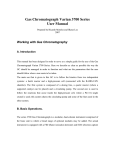
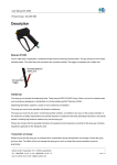
Operating instruction
Description of the equipment for the production of oxides
by chemical vapour deposition
(CVD)
in fixed-bed as well as in fluidized-bed
in room 488 NBCF 05/south
Operators:
Dipl. Ing. Ralf Bergsträßer (room 689 NBCF 04/south, Tel. 22341)
Adelkampstr.5
45147 Essen
(0201) 7204846
1 General Description
The described set-up is used to produce coated oxides such as titanium oxide (TiO2) through
chemical vapour deposition (CVD) of silicon tetrachloride (SiCl4). An oxide is treated either
in solid or in fluidized bed by silicon tetrachloride (SiCl4). After the compound is adsorbed it
must be treated with water and finally calcinated with argon or air.
The maximum temperature that the reaction can reach is 450°C (723 K). The system is heated
by a furnace, in which Duran- or silica reactors are inserted.
Currently the whole system is operating at atmospheric pressure.
Attention: corrosive gases and corrosive liquids can be produced (SiCl4, HCl). If these
corrosive materials leak from the system, corrosion can occur. The equipment is set under the
hood and must be examined by experienced staff.
2 Assembly
The whole equipment is set on aluminium foil (MKS). Tubes and hoses in this system are
made of stainless steel and Teflon.
The schematic of the set-up is shown in Figure 1.
Figure 1 Experimental apparatus of CVD set-up for production of coated oxides.
2.1
Gas supply
Argon or synthetic air gas cylinders (up to 200 bars) are used. The pressure gauge is between
2 and 6 bars. Absence of water for modification of the TiO2 surface with silica is strongly
recommended. Therefore an additional purification of argon is required. An Oxysorb is used
for trapping oxygen and water, before argon flows though the system. The reactant gases are
controlled by mass flow controller (MFC 1-3). The flow can be applied to a solid-bed reactor
(MFC 2, MFC 1 (H6)) or a fluidized-bed reactor (MFC 3, MFC 1 (H6)). The argon flow
(MFC 1) is controlled through a saturator (water) by the valves H4 and H5. An injection
plunger controls the flow of silicon tetrachloride (liquid). During the coating experiments a
SiCl4 flow rate between 0.20 and 2.00 ml/h and a total volume between 0.5 and 5 ml is
applied.
2.2
Reactor
CVD
The reactant gas is heated up to 450 °C (723 K) in the reactor and flows through the TiO2
packing. The system is heated by a furnace. The thermocouple inside the packing measures
and controls the furnace temperature.
The gas, leaving the reactor, is heated to 100 °C (373 K). With the valves TH1-TH3 the flow
can either be passed through two cryo traps or bypassed. To condensate the silicon
tetrachloride in the reaction mixture the two cryo traps route is used. The two cryo traps are
cooled with dry-ice and isopropyl alcohol to –77 °C (196K).
The consumption of silicon tetrachloride is calculated by the amount of generated HCl (see
eq. 1). After the reaction the gas is analysed by an digital titrator with sodium hydroxide
solution (0,1 M). However, to assure trapping all the trace gases the exhaust gas flow is
controlled through a containment, filled with water.
SiCl4 + 2 H 2O → 4 HCl + SiO2
eq. 1
Fluidization
The reactant gas can be used for cold-flow experiment in the fluidized bed. The gases are fed
bottom-up, flowing through the packing and fluidizing the particles. These experiments are
done at room temperature and in the absence of SiCl4.
The states of the fluidization are recorded by a digital camera. To proof a stable fluidization a
differential pressure gauge is applied and the data is collected by a PC.
Above the fluidized bed is an expansion zone, which should avoid the discharge of the
particles.
In order to filter traces of particles, the exhaustion gas is discharged in a beaker filled with
water.
3 Components
The components and their position in the equipment are shown in Figure 2. Additional
informations can be found in the instruction manuals.
Figure 2 Front view of the coating equipment.
1. Reactor
The main part of the equipment is the heated reactor, in which the coating experiment takes
place. A detailed assembly of the components are illustrated as follows:
1.1 Solid-bed reactor
For Duran-reactors a maximum temperature of 250 °C (373K) is allowed.. The oxide
is filled up in the reactor to a packing height of not more than 10 cm (ca. 2.3 g). It is
important that the temperature does not exceed 250 °C (373 K), because of the
material stability. By exceeding the temperature a leak can occur.
However, a silica reactor can be used at higher temperatures (up to 700 °C [973 K]).
Figure 3 View and sketch of the reactor.
1.2 Stainless steel fittings
The reactor entrance (see is 1.1) connects to a argon containing Teflon tube by an
stainless steel – swagelock – connector (SS-6MO-6). To avoid damage, it is important
to use Teflon fittings (T-6M3-1, T-6M4-1) on the glass site.
1.3 GL-Teflon fitting
The exit of the reactor is connected to the heated (100 °C (373 K)) 6 mm Teflon tube
by an GL-Teflon screwing (Semadeni, Laboratory fitting HAT PTFE/PPS GL14 4686,
connector GL14 PTFE 4897)
1.4 Furnace
The required heat for the reactor is generated by a furnace.
The furnace temperature is automatically controlled by a temperature regulator (Fig.
4). Detailed information can be obtained from the controller-manual, which is attached
to the equipment.
Figure 4 Eurotherm-controller
Attention: Before starting the controller, one must fix the thermocouple in the furnace,
Otherwise uncontrolled overheating and massive damage could occur. The
thermocouple must be tested before starting an experiment and it must be replaced if
necessary.
1.5 Inlet system
The used inlet system for SiCl4 is illustrated in Figure 4 (no. 5). The hoses a,b,c
(Perfusor-hoses, Braun, 150 cm, Luer lock, 872296/0) are made of PVC. Hose “a” is
connected to an SiCl4-storage vessel, hose “b” is attached to a syringe, which is
controlled by an injection plunger. Both hoses have direct contact with SiCl4 and have
to be replaced at the end of each experiment. Hose “c” contains argon (MFC 2). The
three hoses are connected by two (“c”,”e”) T-valves (novodirect, Polycarbonat
N13317, N13324). The first step is filling the syringe. Argon is given in the reactor
(“e” open to “d”, “g“ closed to “c”) and the syringe is filled via the storage vessel (“c”
open in all directions). The syringe is filled and emptied until no longer bubbles are
visible in the valves and hoses (as a general rule 3-4 times). The storage valve is cut of
(“a”) and the syringe is fixed in the injection plunger (see also chapter 3.3) and the
experiment starts.
The argon flow is switched off and the valves “b” and “g” get connected. After the
experiment the whole system is purged through with argon.
The SiCl4 containing materials which are in directly contact the reactor (“g”), runs
high reaction temperature. The materials made of PVC are not stable at temperatures
above 200 °C (373 K) and stainless steel tubes would corrode. However Teflon can be
used up to a reaction temperature of 350 °C (573 K), but you have to pay attention,
that the end of the Teflon hose is outside of the reactor, because it is limited to 200 °C
(473 K). At higher temperatures a very thin silica capillary can be used. The capillary
must be handled with care, because of breakage. The transition from soft Luer lock
valves to hard Teflon tube or silica capillary is complicated. First a Tefzel adapter
(novodirect, N24630 or N24814) and second an Omnifit low pressure fitting made of
Teflon (novodirect, N24600) is used. In order to avoid breakage and leakage of the
system all SiCl4 hoses and the thermo couple containing silica capillary are fixed with
tape.
To minimize condensation and adsorption at the inner wall all non SiCl4 containing tubes and
hoses (such as gas supply and the tubes to the analytic) are heated to 100 °C (373 K).
2. Fluidized bed reactor
Figure 5 Fluidized bed reactor.
A second core part of the system is the fluidized bed reactor (Figure 5). The reactor (3) is
made of Duran glass. The inflow gas could either pass through the CVD part or bypassed.
Currently the fluidized bed reactor is not heated. However by inserting the fluidized bed
reactor inside the CVD set-up the reactor could be heated. The reactant gases flowing from
the bottom (6) of the reactor in order to fluidize the bed. The gas tubes at the bottom of the
reactor are connected to MFC 1 and / or MFC 3 by Teflon tubes (5 [Swaglok SS-6MO-6], 4
[grind – 6 mm tube]). To examine the precise dimension of the reactor for fluidization there is
an extended reactor (2) that could be connected to the original fluidized bed reactor to test
higher beds. An expansion zone above the fluidized bed decreases the gas velocity to separate
the particles from the gas. A Teflon tube from the expansion zone is connected to a beaker,
filled with water, to wash out fines. The argon is exhausted in to the hood.
Currently the experiment is conducted at room temperature. A differential pressure gauge is
connected to the fluidized bed reactor in order to measure pressure drop in the bed, however,
in order to avoid corrosion no SiCl4 is used. In the case of heating, The maximum allowable
temperature is 250 °C (523 K).
The states of the fluidization are registered by a digital camera. To proof a stable fluidization
a differential pressure gauge (MKS Baratron type 223BD-00100AAB-SP) is applied and the
data is collected by a PC (further information at the description of the computer program for
the Massflow controllers).
3. Injection plunger
The injection plunger measures and controls the amount of SiCl4 which enters the reactor
(Figure 6). After filling the syringe with SiCl4 (see also chapter 1.5) the syringe is fixed (a).
The ON/OFF switch is at the rear right corner (b).
Figure 6 Injection plunger.
The menu can be selected by pressing the keys çè and SELECT (d). Numeric parameters
are entered with the numeric pad (c) and confirmed with ENTER (c). You have to pay
attention to enter the numbers with 3 decimal places, e.g. 0.500. To start or stop the program
use RUN/STOP bottom. To draw or inject the SiCl4 quickly, push RUN/STOP and ç or è
simultaneously. All informations are shown in the display (f).
Detailed information can be obtained from the controller-manual, which is attached to the
equipment.
4. Heating band
The temperature controller has three different heating zones.
Figure 7 Controller panel for different heating zones: left: not in use, middle: before the
reactor, right: after the reactor.
All non SiCl4 containing tubes are heated to 100 °C (373 K) to avoid adsorption of SiCl4 and /
or HCl at the inner tube walls.
At this time the left controller is not in use, but an additional heating zone for the fluidized
bed reactor or an indicator for the cooling bath could be attached.
The actual usage of the heating zones is written under each of the Bürkert-controllers.
Detailed information can be obtained from the Bürkert-controller-manual, which is attached
to the equipment.
5. Cooling bath
Figure 8 Cooling bath with two cryo traps.
The SiCl4 gas flows into the cooling bath, which is frozen out in one ore two cryo traps (d)
right after its arrival. These traps are connected to the Teflon tubes by GL-connector
(novodirect, Teflon, GL 14, 4897). Tube “a” is connected to the reactor and tube “b” connects
to the digital titrator. Both cryo traps are in line and connected with a short Teflon tube and
GL-connectors. The cryo traps are put in an isopropyl alcohol / dry-ice mixture (-77 °C (196
K), Dewar). It is important to note, that at this time no connected tubes can be placed in the
water due to the low pressure which exist in the system.
6. Massflow controller
The massflow controllers are from Mättig (type: Bronkhorst) and from Brooks.
The adjustment range for the described equipment is listed in the following:
•
MFC 1, for Argon: V& = 0 – 400 ml/min
•
MFC 1, for 1000 ppm oxygen in helium: V& = 0 – 400 ml/min
•
MFC 2, for Argon: V& = 0 – 50 ml/min
•
MFC 3, for Argon: V& = 0 – 3500 ml/min
1
C
2
A
B
7
6
5
4
3
Figure 9 User interface of the PC-Program for MFC´s and differential pressure gauge.
The PC-Program for mass flow controllers, differential pressure gauge and data acquisition is
shown in Figure 9:
The program is divided in three main parts:
A. set values output
B. calibrated value input
C. graphic visualisation and data acquisition
The calibrated value is entered (as percentage of the maximal flow) in section B either
manually (4) or by setting a slide (3). As an alternative a slope can be entered (7). In this case
EN is the final value and %/min is the slope velocity. The set value is shown in section A. The
graph on the screen could show the set and calibrated values. The name of the file is at free
choice (2) and can be chosen under the name the acquisition frequency in respect to the
computer capacity. Elements which are not in use can be hidden (4,5).
The channels are assigned as followed:
1. MFC 1
2. MFC 2
3. MFC 3
4. differential pressure gauge
5. not in use
6. not in use
7. not in use
8. not in use
7. Titration
Figure 10 Titration set-up.
The consumption of SiCl4 in the reaction is calculated by the produced amount of HCl (eq. 1)
SiCl 4 + 2H 2O → 4HCl + SiO2
eq. 1
The generated HCl is titrated automatically with sodium hydroxide solution (0.1 M).
However, if unused SiCl4 enter the system there will be an artificial titration. Therefore it is
necessary to cool the SiCl4 gas in order to prevent its entrance to the system. Figure 11
illustrates the assembly of the titration vessel.
Figure 11 Titration vessel with connectors
The vessel (water) consists of a 4-neck-bottle with GL-connectors. It is cooled with an ice
bath (2) and stirred with a magnetic stirrer (1).
The valves are connected as followed:
GL 16: pH-electrode (4), connected with the titrator
GL 14: titration syringe (5), connected with the titrator
GL 14: Teflon tube (heated HCl gas), connected to the titrator and the reactor
GL 14: exhaustion hose
Figure 12 Assembly of the online titrator (TitroLine alpha).
The used digital titrator (1, TitroLine alpha) has a 50 ml container for titration solutuion and a
keypad (2). The pH-electrode is connected to the DIN port “Elect” by the electrode wire. The
titration syringe is connected to the front side valve (6) and the NaOH storage (4) is connected
to the backside valve (6).
If all connections are linked and controlled, the titrator can be switched ON. The electrode is
calibrated by buffer solution with pH 4 and pH 7 (press “cal” on the keypad 2). The titrator
has different programs. To start a program press “start” at the key-pad and enter a name. Press
“enter” to confirm the name and to start the titration.
To obtain the data one could save the data on a PC (5) or print it directly.
Further information can be obtained from the controller-manual, which is attached to the
equipment.
To transfer the data to a PC, the program ARDTest.exe must be started. It is important to note,
that the program must be started, before choosing the method and calibrate.
1
5
4
2
3
Figure 13 User interface of the PC-program ARDTest.exe.
To ensure transfer of data between titrator and PC, Port 2 (1) and channel 12 (= “Adresse”
12) must be chosen. To test the connection you can select “Report Hardware” (4). In the
lower panel (2) a short string of data is displayed and the name TitroLine alpha must be
visible. To start the data collection the command RH must be entered (5).
The collection of data is stopped by pressing the OK button. The file can be imported in any
editing programs.
Further information can be extracted from the attached user-manual of the titrator.
4
The start up procedure for CVD
The chosen reactor is filled with oxide and than heated (up to Tmax = 450 °C (723 K)) in a
stream of inert gases to remove adsorbents. The reaction temperature is set and the CVD with
SiCl4 is accomplished (see also chapter 3.1). Different parameters such as time and/or volume
can be chosen. A variety of samples get hydrolysed with water (Ar-H2O) at the reaction
temperature. All samples are calcined at the end of an experiment by air or argon.
Table 2.2 Flow sheet of a CVD-experiment
1. Weigh the P25
2. Fill the reactor
a. ca. 1 cm quartz wool
b. Fill the reactor with the weighted amount of P25
c. Close the reactor with the septum (including the thermo couple capillary and
the inlet tubes for SiCl4 and inert gas)
3. Installation of the reactor
a. Connect inert gas (swagelok)
b. Connect syringe (luer lok)
c. Close connection at the bottom
4. Adjust inert gas flow
5. Control leakage
6. Heat up the tubes by setting the heating zones to 100 °C (373 K). All the tubes, which
get in contact with water in the previous experiment must be heated with a hot air unit
or heating bands.
7. Start the temperature program for the furnace
8. During the heat up:
a. Calibrate the electrode (pH 7 and pH 10)
b. Fill the syringe and install it in the syringe plunger (check for bubbles and fill
SiCl4 up to the T-valve, which is directly connected to the reactor)
c. Prepare the dry-ice / isopropyl alcohol quenching bath
9. At the end of the heating, install the cryo traps. Be aware, that no attached tube is in
contact with water (exhaustion gas and analytic)
10. Set the reaction temperature
11. Analytic:
a. Fill the vessel (35 ml H2O)
b. Close the connections
c. Check leakage
d. Start the analytic method (at least 6 h)
12. Stop the upside inert gas stream and add the SiCl4 gas flow
13. After finishing the addition flush all SiCl4-containig tubes and hoses with a low flow
inert gas stream
14. Flow the inert gas stream through the saturator and be aware that the cryo traps are
bypassed. Restart the analytic method
15. Dry out and calcine
1 – 1,5 h
3 – 3,5 h
0,5 h
2–4 h
>1h
Over night
1–2h
The SiCl4 which did not react is frozen out in the cryo traps and the generated HCl is
neutralized with a sodium hydroxide solution (0.1M). The pH-value is kept constant and the
needed volume of NaOH used in the neutralization is registered. The data can be obtained via
PC.
Stop the experiment:
The heater must be shut off and the reactor must be reached to room temperature by a stream
of inert gas.
Silicon tetrachloride is hydrolysed by NaOH at the end of an experiment. An ice bath is used
to cool the system.
All parts which are in direct contact of SiCl4 must be cleaned accurately and if it is necessary
they must be replaced.
5
Potential risks
SiCl4 and HCl react fierce with water. They irritate the eyes, respiratory organ and the skin
and they can generate severe corrosion.
All bases react with acids fierce and exothermic, also they generate heat by diluting them with
water. All bases and acids react corrosive. Bases amplify vasculars and penetrate deep inside
the tissue. Never neutralize corrosion of bases with acids and vice versa.
6
Procedure to minimize risks
The receiver must be cooled with ice water, when working with SiCl4 and / or NaOH.
SiCl4 is only allowed to be stored under the aspirator.
Concentrated Acids are only allowed to handle under the aspirator. Gas/smoke/steam/aerosol
of acids and bases must never be inhalated.
Because of the risks mentioned above the equipment is installed in the aspirator.
When working with SiCl4 Neopren- or Nitril- protection gloves can provide a short-time
splash guard. If needed a protection apron must be worn. The following materials for
protection gloved are not adequate: Naturkautschuk/Naturlatex-NR, Polychloropren-CR,
Butylkautschuk-Butyl, Polyvinylchlorid-PVC.
Adequate protection gloves for the directed exposion with NaOH is Neopren/Latex, as a
short-time splash guard Nitril can be used.
Goggles must be worn at the work with SiCl4, HCl, NaOH.
When working with fines (TiO2) a dust-musk must be worn.
The general safety rules in the laboratory have to be attended.
A leak test must be run before starting the experimental work. All volume flows (specially the
SiCl4 flow) have to be controlled all the time.
The pressure of the gas bottles have to be controlled continuous. At a sudden pressure drop
the connection must be checked and if needed the gas bottles have to be closed and the
experiment must be stopped.
The controlling PC and the titrator are not in the aspirator, separated from the equipment.
Electric wires, thermo couples and the furnace have to be controlled continuous and repaired
or replaced if necessary.
7
Measures in case of an emergency
If a fault occurs, despite safety precautions, the standard shut down procedure must be
initialised. Furthermore all heating bands must be switched off.
At the first sign of disintegration or chemical permeability the protection gloves must be taken
of and renewed.
Small amounts of slopped liquids can be dilute with plenty water and be flushed away.
Emergency and eye washes are installed in the neighbouring room NC 05 / 487.
8
Used chemicals and their material properties
Silica tetrachloride from Aldrich
SiCl4
R: 14-35-37
• Reacts violently with water.
•
Causes severe burns
•
Irritating to respiratory system
S: 7/9-26-36/37/39-45
•
Keep container tightly closed and in a well-ventilated place
•
In case of contact with eyes, rinse immediately with plenty of water and
seek medical advice
•
Wear suitable protective clothing, gloves and eye/face protection
•
In case of accident or if you feel unwell, seek medical advice immediately
(show the label where possible).
The equipment is installed in an aspirator, because auf the risks mentioned above.
When working with SiCl4 Neopren- or Nitril- protection gloves can provide a short-time
splash guard. If needed a protection apron must be worn. The following materials for
protection gloved are not adequate: Naturkautschuk/Naturlatex-NR, Polychloropren-CR,
Butylkautschuk-Butyl, Polyvinylchlorid-PVC.
At the first sign of disintegration or chemical permeability the protection gloves must be taken
of and renewed.
Small amounts of slopped liquids can be dilute with plenty water and be flushed away.
An exposure can cause skin irritation, especially when the skin is wet. Severe irritation of the
respiratory organ or intestinal tract are generally possible. Medical aid must be accomplished
after inhalation. The person must be brought to fresh air and be supported with oxygen if
needed. Exposed skin must be flushed with water for at least 15 min. Contaminated cloth and
shoes must be put of and in the last step the irritated skin can be swabbed with
Polyethylenglykol-400.
In the cause of swallowing never induce vomiting. Directly contact a doctor and give the
person a lot of water or milk to drink.
In cause of an exposure to the eyes hold up the eyelid and flush with water for at least 15 min.
A doctor must be consulted directly.
Buffer Solution pH 7 (di-sodium hydrogenphosphate/ kalium hydrogenphosphat)
from J.T. Baker
R: --S: ---
Buffer Solution pH 10 (boric acid/sodium chloride / sodium hydroxide)
from Riedel-de-Haen
R: 36/37/38
• Irritating to eyes, respiratory system and skin
S: 26-37/39
• In case of contact with eyes, rinse immediately with plenty of water
and seek medical advice
•
Wear suitable gloves and eye/face protection
At the work buffer solution pH 10 with nitril protection gloves can be used.
The use of goggles is a must.
Silica wool, Roth
R: --S: --A dusk mask and protection gloves should be worn when working with silica wool.
Sodium hydroxide, solid from J. T. Baker
Sodium dye 0.1 mol/l
R: 35
• Causes severe burns
S: 26-37/39-45
•
In case of contact with eyes, rinse immediately with plenty of water
and seek medical advice
•
Wear suitable gloves and eye/face protection
•
In case of accident or if you feel unwell, seek medical advice
immediately (show the label where possible).
Titandioxid P25 from Degussa
R: --S: 25
• Avoid contact with eyes
A dusk mask and protection gloves should be worn as prevention when working with titandioxide.
9
Material specified operation instructions
All the safety instructions are for the chemical in room 488 NBCF 05/south.
The university wide emergency
number is: 3333
In the cause of questions please contact one of the operators:
Dr. Simone Geisler (Raum 689 NBCF 04/Süd, Tel. 22341)
Tanneneck 1a, 45525 Hattingen, (02324) 28257
Dipl. Ing. Ralf Bergsträßer (NBCF 04/Süd, Tel. 22341)
Adelkampstr.5, 45147 Essen, (0201) 7204846
28