1
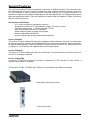
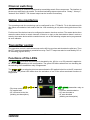
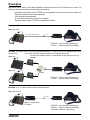
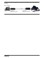
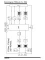
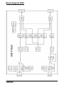
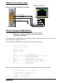
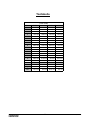
Line Interface
FT 634a, FT 634aC, FT 634aCL
Contents
page
Technical Data
General Features
Channel switching
Option line monitoring
Transmitter control
Functions of the LEDs
Examples
Jumper
Block diagram FT634a (C, CL, TRC)
Block diagram DSP
Pinout
RS232-connecting cable
Service program/Adjustment
Programming
Decoder functions FT634aC
Alarm transmission from FT634aC to Major 4a/5a
Inputs initiating tone sequences
Option: Line monitoring (FT 634a CL)
Tontabelle
General Safety Instructions
Terms and abbreviations
-2Kompetent für Elektroniksysteme
3
4
5
5
5
5
6
8
9
10
11
13
13
15
18
20
21
22
23
24
25
ft634a (06.02.2014)
Technical Data
Voltage of operation
+12V DC +/-30%
Current demand
ca. 100 mA
Fuse
1 A, self-resetting
Weight
ca. 525 g
Dimensions W x H x D
104 x 44 x 175 mm
Frequency of pilot tone
ex factory setting: 3300 Hz
Pilot tone decoder
+/- 0,8 % (+/- 26 Hz)
Response time
< 20 ms
Release time
< 40 ms
min. pilot tone level at measuring (monitor.)point
75 mV
Notchfilter pilot tone suppression
> 50 dB
2- resp. 4-wire
Input level 2-wire
Adjustment range 2-wire
Input level 4-wire
Adjustment range 4-wire
Input impedance
Output level 2-wire
Pilot tone 2-wire
Output level 4-wire
Pilot tone 4-wire
Output impedance 2-wire
Output impedance 4-wire
-10 dBm nominally, 250 mV
-41 dBm to -1 dBm, 7 mV to 700 mV
-9 dBm nominally, 275 mV
-40 dBm to +1 dBm, 8 mV to 850 mV
2-wire Zr or 600 Ohm, 4-wire 600 Ohm
-10 dBm, 250 mV (or: -19 dBm, 190 mV)
-12 dBm, 200 mV
-14 dBm, 150 mV (or: -5 dBm, 450 mV)
-16 dBm, 125 mV
Zr or 600 Ohm
600 Ohm
Interface radio device resp. desk top control
Input level
+ 3 dBm nominally, 1100 mV
Adjustment range
- 24 to + 6 dBm, 50 mV to 1550 mV
Input impedance
600 Ohm
Output level
- 17 dBm ex factory setting, 100 mV
Adjustment range
- 30 to + 8 dBm, 25 mV to 2000 mV
Output impedance
600 Ohm
-3Kompetent für Elektroniksysteme
ft634a (06.02.2014)
General Features
The new line interface FT634a is completely constructed in SMD-technology. The connections are
pin-compatible with the former version, but instead of male connectors there are female connectors.
The line interface is used to remotely operate a two-way radio by a 2- or 4-wire connection. It is
possible to bridge very long distances depending on the cable attenuation. The FT634a is the simplest
and most reasonable version. There are 6 different versions of the line interface FT634a. All versions
offer the following features:
All versions of the FT634a
- 2- or 4-wire connection (selectable by jumper)
- Impedance 600 Ohm or Zr (selectabel by jumper) (Zr only for 2-wire)
- Connector radio device --> AF-in/output and PTT-out
- Pilot tone decoder 3300 Hz or DC-decoder
- Serial interface RS232 to adjust and program
- All levels adjustable with RS232
- All AF-in/outputs galvanically separated (transformer)
Version FT634aC
The version FT634aC additionally offers the possibility to switch channels remotely. The information
for switching channels remotely are transmitted by 5-tone. A pilot tone encoder for 3300 Hz and a DCencoder are also included. These are needed to connect the line interface to an operation terminal
(e.g Major 6). The FT634aC has 8 digital inputs and 8 digital outputs.
Version FT634aCL
The version FT634aCL additionally offers line monitoring. This means that the connection of the 2/4wire line is constantly monitored.
Version FT634aTRC
In version FT634aTRC the pilot-tone encoder is replaced by a TRC encoder. For this version, a
separate user manual is available
The versions FT634a, FT634aC and FT634aCL are available in two different housings.
- black flange aluminum housing
- 19 inch plug-in unit
-4Kompetent für Elektroniksysteme
ft634a (06.02.2014)
Channel switching
Remote switching of channels is achieved by transmitting certain 5-tone sequences. The interface to
the two-way radio device is parallel. The channel switching status output can be "binary", "binary-1",
"decimal" and "2xBCD". The channel output can be inverted if necessary.
Option line monitoring
The operating mode line monitoring can be configured for the FT634aCL. To do this devices with
this option are needed at both ends of the line. Line monitoring is only active during idle times of the
wire.
For this one of the devices has to be configured as master, the other as slave. The master device then
scans the slave device in certain intervals. If there is no reply or the slave-device doesn´t receive a
scan by the master-device within a certain interval, one of the switching outputs can be programmed
as error indicator.
Transmitter control
The transmitter control is activated as soon as the AC-line receives and decodes the pilot tone. Then
the PTT-output is switched by a potential-free relay. The PTT-output can also be controlled by DC- or
AF-decoding (register 053/1).
Functions of the LEDs
The green LED is on when the pilot tone is decoded by the AC-line or a DC potential is applied or
AF is decoded depending on the configuration. The green LED blinks when there is a decoding but
the switching of the transmitter relay is suppressed.
The yellow LED is on when the pilot tone was activated or DC applied to the line or the AF connected
to the line. The yellow LED blinks when the activation of one of the afore-mentioned functions is
suppressed.
LED yellow
LED green transmitter relay on
- Pilot tone turned on or
- DC applied and
- AF connected to the line
(blinking see description)
because
- Pilot tone was decoded or
- DC was decoded or
- AF was decoded
(blinking see description)
-5Kompetent für Elektroniksysteme
ft634a (06.02.2014)
Examples
Depending on the setup of the radio installation different versions of the FT634a can be used. The
following questions should be answered when planning:
- Interface connection of the FT634a to an operation terminal or a two-way radio set
- Remote channel switching necessary
- Line monitoring necessary
- 2- or 4-wire connection, simplex or duplex
- Remote station also FT634a or operation terminal
Example 1: 2- or 4-wire remote control via private lines
Major 4a or 5a
AC- or DC- remote control
2
or 4
FT634aC (with channel switching) or
FT634a (without channel switching)
Example 2: Parallel circuit of several operation terminals --> LIM AC has to be equipped with notch
for pilot tone.
On private lines the remote control can be carried out by DC.
Major 5a
Here the two LIM AC and the notch filters for the pilot tone are not
needed.
2
LIM AC
2
Major 4a
2
FT624
FT634aC (with channel switching) or
FT634a (without channel switching)
LIM AC
Example 3: 2- or 4-wire remote control via leased lines.
Major 4a, 5a or 6
2
oder 4
LIM AC (only 2-wire)
FT634aC
FT634aC (with channel switching) or
FT634a (without channel switching)
FT634aCL (with line monitoring)
-6-
Kompetent für Elektroniksysteme
ft634a (06.02.2014)
Example 4: Operation terminal Major 6 via 2-wire to the multi-channel radio set (with option line
monitoring)
Major 6, 4a or 5a
2
FT634aCL
(with line monitoring)
FT634aCL
(with line monitoring)
-7Kompetent für Elektroniksysteme
ft634a (06.02.2014)
Jumper
Different configurations can be adjusted with the internal jumpers . For example you can choose
between 2- or 4-wire connections. The functions of the different jumpers are printed directly onto the
circuit board.
Jumper setting normal, 2D, Zr, AC (ex factory)
2D
4D
Zr
600
AC
DC
Jumper setting 2D, Zr, DC
=
=
=
=
=
=
=
2 wire
4 wire
complex impedance
real impedance 600 Ohm
remote control by AC voltage
remote control by DC voltage
jumper
Jumper setting 2D, 600 Ohm, AC
Jumper setting 2D, 600 Ohm, DC
Jumper setting 4D, 600 Ohm, DC
Jumper setting 4D, 600 Ohm, AC
-8Kompetent für Elektroniksysteme
ft634a (06.02.2014)
Block diagram FT634a (C, CL, TRC)
-9Kompetent für Elektroniksysteme
ft634a (06.02.2014)
Block diagram DSP
- 10 Kompetent für Elektroniksysteme
ft634a (06.02.2014)
Pinout
The pinout is the same for all types of the FT634a.
8-pin Western jack "RS232"
LED yellow
LED green, transmitter relay on, because
- pilot tone on or
- DC on and
- AF connected to line
(blinking see description)
I/O 12
(in/output)
I/O 11
(in/output)
I/O 10
(in/output)
I/O 09
(in/output)
I/O 08
(in/output)
GND
(in/output)
RS232 RxD (input)
RS232 TxD (output)
9-pin Sub-D jack
- pilot tone decoded or
- DC decoded or
- AF decoded
(blinking see description)
8
7
6
5
4
3
2
1
"LINE"
I/O: Line, 2D, 4D out
1
free
2
I/O: GND
3
free
4
I/O: Line, 2D, 4D in
5
- 11 Kompetent für Elektroniksysteme
6
OUT: Line, 4D out
7
I/O: I/O 13 (Pull-up 5V)
8
I/O: I/O 4 (o.C.)
9
IN: Line, 4D in
ft634a (06.02.2014)
15-pole Sub-D jack
"RADIO"
IN : + 12 V
1
OUT: PTT-Relay
2
OUT: PTT-Relay
3
OUT: radio, AF out
4
OUT: radio, AF out
5
I/O: I/O 0 (o.C.)
6
I/O: I/O 1 (o.C.)
7
I/O: GND
8
9
IN: + 12 V
10 IN: Squelch
11 IN: radio, AF in
12 IN: radio, AF in
13 I/O: I/O 2 (o.C.)
14 I/O: I/O 3 (o.C.)
15 I/O: GND
64-pole bus connector, 19 inch version
Pin
A
C
-----------------------------------------------------------------------------------------------------------1
IN :
+ 12 Volt
IN:
+ 12 Volt
2
IN :
Analog 1 (0-7V)
IN:
Analog 2 (0-7V)
3
I/O:
I/O 08 (Pull-up 5V)
4
I/O:
I/O 09 (Pull-up 5V)
IN :
Line, 4D in
5
I/O:
I/O 10 (Pull-up 5V)
OUT: Line, 4D out
6
I/O:
I/O 11 (Pull-up 5V)
I/O:
Line, 2D, 4D out
7
I/O:
I/O 12 (Pull-up 5V)
I/O:
Line, 2D, 4D in
8
I/O:
I/O 13 (Pull-up 5V)
OUT: bus, AF RADIO>BUS
9
I/O:
I/O 14 (Pull-up 5V)
IN :
bus, AF BUS>LINE
10
I/O:
I/O 15 (Pull-up 5V)
IN :
radio, AF in
11
I/O:
I/O 0 (o.C.)
IN :
radio, AF in
12
I/O:
I/O 1 (o.C.)
13
I/O:
I/O 2 (o.C.)
14
I/O:
I/O 3 (o.C.)
15
I/O:
I/O 4 (o.C.)
OUT: radio, AF out
16
I/O:
I/O 5 (o.C.)
OUT: radio, AF out
17
I/O:
I/O 6 (o.C.)
I/O:
I/O 7 (o.C.)
18
IN :
plug-in position config. 1
19
IN :
plug-in position config. 2
20
IN :
plug-in position config. 3
IN :
bus, AF BUS>RADIO
21
IN :
plug-in position config. 4
I/O:
DATA (RS232_UGA)
22
IN :
RXD (RS232_ext)
OUT: TXD (RS232_ext)
23
I/O:
SDA (I2C)
I/O:
SCL (I2C)
24
OUT: PTT-Relay
OUT: PTT-Relay
25
26
IN :
Squelch
27
28
29
30
31
OUT: +3,3V
OUT: +5V
32
I/O:
GND
I/O:
GND
- 12 Kompetent für Elektroniksysteme
ft634a (06.02.2014)
RS232-connecting cable
RS232 jack on FT634
Computer equipped with RS232 9-pole jack
2
RxD RS232
3
TxD RS232
5
GND
GND
RxD
TxD
3
2
1
Service program/Adjustment
The FT 634aC has a RS-232 interface with the following specifications
9600 Baud, 1 Startbit, 8 Data bits, No Parity, 1 Stop bit,
no protocol or Xon/Xoff
For communication with Windows e.g. the terminal program "HyperTerminal" can be used. For Linux
we recommend the program minicom.
After hitting the key ENTER the terminal program prompts you for input:
Online - Monitor FT634a
----------------------Software: FT634aC
Version : V1.00
SW-date: 17.10.06
Rxxx................read register xxx
Pxxx yyyyyyyy.......program register xxx with yyyyyyyy
A...................adjust potentiometer
Tx..................TX-relay on/off (1/0)
Kxx.................switch channel xx (00-99,?)
Ixxxx...............tone generator on with xxxxHz
$xxxxx .............transmit tone sequence xxxxx
Q...................reset software
X...................end monitor
After hitting the key A the monitor prompts you for adjustment with the following screen :
Which potentiometer is to be adjusted?
1:
2:
3:
4:
x:
input of line - amplification
input of line - equalization
output to two-way radio
input of two-way radio
end
- 13 Kompetent für Elektroniksysteme
ft634a (06.02.2014)
The screen for potentiometer 1:
(The actual reading of the internal reference value iis shown after changing or blank key.)
Adjustment potentiometer 1:
Feed with required level into line-input at 1000Hz.
Adjust ‚Line‘ to 300mV at internal reference value.
Initial value: adjustment potentiometer 1:
Feed with required level into line-input at 1000Hz.
Adjust ‚Line‘ to 300mV at internal reference value.
Initial value: 014 (min:000 max:255) level: 000 mV reference value:
300 mV
Keys:
<+> : +1
<*> : +10
<-> : -1
<_> : -10
< > : measuring only
<a> : self-adjustment
<p> : programming
<x> : cancel
The screen for potentiometer 2:
Adjustment potentiometer 2:
Feed with required level at line-input at 3400Hz.
Adjust ‚Line‘ to 300mV at internal reference value.
Initial value: 057 (min:000 max:255) level: 000 mV required value:
300 mV
Keys:
<+> : +1
<*> : +10
<-> : -1
<_> : -10
< > : measuring only
<a> : self-adjustment
<p> : programming
<x> : cancel
The screen for potentiometer 3:
Adjustment potentiometer 3:
Feed with required level at line-input at 1000Hz.
Adjustment pot 1 and 2 (reference value ‚Line‘ = 300mV).
Adjustment radio-output at required value (required modulation
depth).
Initial value: 015 (min:000 max:255)
Keys:
<+> : +1
<*> : +10
<-> : -1
<_> : -10
<t> : transmitter on/off
<p> : programming
<x> : cancel
The screen for potentiometer 4:
Adjustment potentiometer 4:
Feed at radio input with required level at 1000Hz.
Adjust at internal reference value ‚Radio‘ to 300mV.
Initial value: 160 (min:000 max:255) level: 000 mV required value:
300 mV
Keys:
<+> : +1
<*> : +10
<-> : -1
<_> : -10
< > : measuring only
<a> : self-adjustment
<p> : programming
<x> : cancel
- 14 Kompetent für Elektroniksysteme
ft634a (06.02.2014)
Programming
Reg. Default
Description
050 03100320 AF-mute level
1.+2. digit:
3.+4. digit:
5.+6. digit:
7.+8. digit:
052
12500128 Pilot tone
1. digit:
2. digit:
3. digit:
4. digit:
5.-8. digit:
EEPROM-Register FT634a
ca. nn*0,9mV threshold AF-mute line>radio activation
ca. nn*0,9mV threshold AF-mute line>radio deactivation
ca. nn*0,9mV threshold AF-mute line>line activation
ca. nn*0,9mV threshold AF-mute radio>line deactivation
pilot tone filter frequency
0=no filter
1=3300Hz
2=3000Hz
3=2800Hz
4=3320Hz
5=2982Hz
6=3850Hz
pilot tone detection, n*5ms decoding until on
pilot tone detection, n*5ms no decoding until off
pilot tone decoder frequency (like 1.digit), if 1.digit=0
pilot tone detection, min.level (0-9999) 0128=75mV,
*2=-3dB;/2=+3dB sensitivity
053
12211220 TX-configuration
1. digit:
TX-decoder 0=off, 1=PIL, 2=DC, 3=PIL+DC, 4=AF-squelch
2. digit:
operating mode:
0: 4-wire, low amplification of line (-25...0dBm)
1: 4-wire, high amplification of line (-40...-15dBm)
2: 2-wire, low amplification of line (-25...0dBm)
3: 2-wire, high amplification of line (-40...-15dBm)
3. digit:
priority
0: none
1: RX before TX
2: TX before RX
3: first come, first served...
4. digit:
AF-directions without RX, without TX
5. digit:
AF-directions with RX, without TX
6. digit:
AF-directions without RX, with TX
7. digit:
AF-directions with RX, with TX
4. to 7. digit:
0=RADIO>LINE off, LINE>RADIO off
1=RADIO>LINE on , LINE>RADIO off
2=RADIO>LINE off, LINE>RADIO on
3=RADIO>LINE on , LINE>RADIO on
8. digit:
line amplification
0= auto, amplification low at 4-D, high at 2-D
1=amplification low
2=amplification high
RX meaning SQL-input (056/1), TX means TX-decoder (053/1)
054
02604010 AF-squelch configuration
1.-2. digit:
n*5ms above threshold, until SQL on
3.-4. digit:
ca. nn*1,8mV threshold AF on
5.-6. digit:
n*5ms below threshold, until SQL off
7.-8. digit:
ca. nn*1,8mV threshold AF off
055
10100000 Advance time register
1.+2. digit:
nn*10ms advance time
3.+4. digit:
nn*10ms delay time
- 15 -
Kompetent für Elektroniksysteme
ft634a (06.02.2014)
056
00051205 Squelch configuration
1. digit:
squelch input
0: active low, pullup on
1: active high, pullup off
2: free (audio squelch)
3: free (phantom)
4: active low, pullup off
5: active high, pullup on
3.+4. digit:
nn*10ms TX-blocking period after own AF on line, only 2-wire
5.+6. digit:
nn*10ms TX-blocking period after own DC on line, only 2-wire
7.+8. digit:
nn*10ms TX-blocking-period after own pilot tone on line, 2-wire
057
00000000 1.
063
BCD00000 Channel switching register
1.-3. digit:
digits 1-3 of the remote channel switching sequence
064
00100000 Channel register
1. digit:
save channel y=1, n=0
2.+3. digit:
channel 00-99
065
30100000 Blocking-periods for RX and TX
1.+2. digit:
nn * 10 ms before channel switching
3.+4. digit:
nn * 10 ms after channel switching
066
01080000 Channel configuration
2. digit:
channel output
0: none
1: decimal
2: binary-1
3: binary
4: 2xBCD
3. digit:
0: channel output normal
1: channel output inverted
4. digit:
number of channel bits (0-8)
5. digit:
0: channel acknowledgement normal (BCDxy)
1: channel acknowledgement Major6 (CBDxy)
2: channel acknowledgement normal with line activation
(pilot or DC like 069/1)
3: channel acknowledgement Major6 with line activation
(pilot or DC like 069/1)
7. digit:
substitution channel bit for I/O4, if I/O4 is used for line
activation
(register 069/1=3)
068
00220011 Pilot-tone: rate of increase/decrease
1.-4. digit:
rate of increase (level steps per control point)
(0022 corresponds to a total increase time of 10 ms)
5.-8. digit:
rate of decrease (level steps per control point)
(0011 corresponds to a total decrease time of 20 ms)
069
00000100 RX-configuration
1. digit:
RX-signaling to line
0: programmed pilot tone
digit:
language of online monitor
0: German
1: English
2: French
3: Dutch
4: Italian
- 16 Kompetent für Elektroniksysteme
ft634a (06.02.2014)
2.-5. digit:
6. digit:
7.
digit:
2: DC
3=I/O4
4=PTT at 9pole DSub line connector ST2, Pin8
pilot tone frequency in Hz
pilot tone filter frequency
0=no filter
1=3300Hz
2=3000Hz
3=2800Hz
4=3320Hz
5=2982Hz
6=3850Hz
line filter, 0=off, 1=on (bandpass 300-3400Hz)
080
01810000 Decoder reference 1
1.-3. digit:
nnn*5ms max. tone duration 1st tone
4.+5. digit:
nn*5ms min. tone duration all tones
081
01800000 Decoder reference 2
1.-3. digit:
nnn*5ms max. tone duration from 2nd tone on
5. digit:
tone calling system 0:ZVEI, 1:CCIR, 2:ZVEI2, 3:EEA, 4:ZVEI3
082
07707000 Encoder reference
1.+2. digit:
nn * 10ms tone duration 1st tone
3. digit:
n * 10ms tone duration all other tones
4.+5. digit:
nn * 10ms duration of break
083
10001000
103
DCBCDCBC Configuration switching inputs FT634C
1.-4. digit:
tone sequence digits 1-4
5.-8. digit:
expected acknowledgement
230
00025560 4.-8. digit:
multiplicator for output level line>radio (0-32768)
234
00008300 4.-8. digit:
multiplicator for output level tone>radio (0-32768)
236
00000000 4.-8. digit:
multiplicator for output level pilot>radio (0-32768)
242
00025560 4.-8. digit:
multiplicator for output level radio>line (0-32768)
244
00008300 4.-8. digit:
multiplicator for output level tone>line (0-32768)
246
00006400 4.-8. digit:
multiplicator for output level pilot>line (0-32768)
250
00000128 4.-8. digit:
min. level for tone decoding of radio (0-32768)
251
00000128 4.-8. digit:
min. level for tone decoding of line (0-32768)
Tone duration single-tone and special tone decoder
1.+2.digit: minimum tone duration single-tone decoding *100ms (für Reg.073/1)
3.+4.digit: maximum tone duration single-tone decoding *100ms
00 = decoding as soon as minimum duration is reached
>00= decoding, if tone duration is between min and max
5.+6.digit: minimum tone duration special tone decoding *100ms (for reg.073/3)
7.+8.digit: maximum tone duration special tone decoding *100ms
00 = decoding as soon as minimal duration is reached
>00= decoding, if tone duration is between min and max
- 17 Kompetent für Elektroniksysteme
ft634a (06.02.2014)
Decoder functions FT634aC
The FT634aC contains 30 decoder registers plus one configuration register each.
The following registers are used for the decoder functions:
000 Decoder 1
001 Decoder 2
002 Decoder 3
003 Decoder 4
004 Decoder 5
005 Decoder 6
006 Decoder 7
007 Decoder 8
008 Decoder 9
009 Decoder 10
020 Decoder 11
021 Decoder 12
022 Decoder 13
023 Decoder 14
024 Decoder 15
025 Decoder 16
026 Decoder 17
027 Decoder 18
028 Decoder 19
029 Decoder 20
200 Decoder 21
201 Decoder 22
202 Decoder 23
203 Decoder 24
204 Decoder 25
205 Decoder 26
206 Decoder 27
207 Decoder 28
208 Decoder 29
209 Decoder 30
000-009, 020-029, 200-209:
1.-8.St.: 0-E = tones to decode (from chosen tone system)
F = every tone is accepted at digits coded with 'F'
All unused digits need to be coded with 'F‘ as well!!
010 Configuration for decoder 1
011 Configuration for decoder 2
012 Configuration for decoder 3
013 Configuration for decoder 4
014 Configuration for decoder 5
015 Configuration for decoder 6
016 Configuration for decoder 7
017 Configuration for decoder 8
018 Configuration for decoder 9
019 Configuration for decoder 10
030 Configuration for decoder 11
031 Configuration for decoder 12
032 Configuration for decoder 13
033 Configuration for decoder 14
034 Configuration for decoder 15
035 Configuration for decoder 16
036 Configuration for decoder 17
- 18 Kompetent für Elektroniksysteme
ft634a (06.02.2014)
037 Configuration for decoder 18
038 Configuration for decoder 19
039 Configuration for decoder 20
210 Configuration for decoder 21
211 Configuration for decoder 22
212 Configuration for decoder 23
213 Configuration for decoder 24
214 Configuration for decoder 25
215 Configuration for decoder 26
216 Configuration for decoder 27
217 Configuration for decoder 28
218 Configuration for decoder 29
219 Configuration for decoder 30
010-019, 030-039, 210-219:
1.digit:
0 = decoder off
1 = decoding from line
2 = decoding from radio
3 = decoding both ways
2.digit: 5-F = number of tones in the tone sequence (5-15 tones)
(the decoder always compares the length of the tone sequence and the first 8
digits that are coded in the decoder register)
3.digit: 0 = function 0: switch output
for function 0:
4.digit: 0-F = number of the switching output I/O 0 - I/O 15
5.digit: 0 = switch off output for the duration defined in digits 6-8
1 = switch on output
E = toggle output (on-off-on...)
6.-8.St.: nnn * 100ms switching time, 000 = switch permanently
095 Configuration I/O 0-7
096 Configuration I/O 8-15
095-096:
1.digit: 0 = I/O 0 (8) is output
1 = I/O 0 (8) is input
...
8.digit: 0 = I/O 7 (15) is output
1 = I/O 7 (15) is input
Example: 5-tone sequence 12345 received from the radio is to activate I/O 15 für 3 seconds.
020: 12345FFF
030: 250F1030
096: xxxxxxx0
- 19 Kompetent für Elektroniksysteme
ft634a (06.02.2014)
Alarm transmission from FT634aC to Major 4a/5a
Up to 3 alarms can be transmitted from the FT634aC to a Major 4a/5a. The FT634aC instantly
transmits an occuring change of the alarm inputs to the Major. As long as no acknowledgement
is received, up to 3 repetitions are transmitted. If still no acknowledgement was received,
transmission is restarted after 1 min. The Major displays a newly received alarm at once. The
user needs to acknowledge the alarms using #. All alarms that occurred are displayed until they
are acknowledged, even if they are no longer active. In the latter case, the current alarm status is
displayed after the user's acknowledgement. This status must again be acknowledged.
FT634aC:
Register 095: Configuration for I/O 0-7 (0=output, 1=input)
Register 096: Configuration für I/O 8-15 (0=output, 1=input)
Register 104: digit 1-4: tone sequence for alarmswitching (ABC0)
digit 5: always transmit alarm tone sequence after power-on, even if no alarm is active y/n (1/0)
Register 108: Function I/O 0 passive>active (high>low)
Register 109: Function I/O 0 active>passive (low>high)
...
Register 124: Function I/O 8 passive>active (high>low)
Register 125: Function I/O 8 active>passive (low>high)
...
Register 138: Function I/O 15 passive>active (high>low)
Register 139: Function I/O 15 active>passive (low>high)
Function alarm input (must be coded in register 108-139)
1. digit: 2=function alarm input
2. digit: input for: 0=emergency power supply, 1=housebreaking, 2=alarm
3. digit: 0: alarm off, 1: alarm active
Default values for alarm transmission:
Register 096: 111xxxxx (I/O 8,9,10 are inputs)
Register 104: ABC01xxx (transmits alarm tone sequence ABC0x after power-on)
Register 124: 201xxxxx I/O 8: emergency power supply input, low=active
Register 125: 200xxxxx I/O 8: emergency power supply input, high=passive
Register 126: 211xxxxx I/O 9: housebreaking input, low=active
Register 127: 210xxxxx I/O 9: housebreaking input, high=passive
Register 128: 221xxxxx I/O 10: alarm input, low=active
Register 129: 220xxxxx I/O 10: alarm input, high=passive
Major 4a/5a:
Register 075:
digit 1-4: alarm tone sequence (ABC0)
digit 5: PTT used for acknowledgement/alarm request
5 = with pilot-tone
6 = w/o pilot-tone
7 = w/o pilot-tone, w/o TX
Register 076: Configuration for alarm decoder
digit 1: alarm tone type (signaling tone for the user of the Major)
digit 2: duration of the alarm tone *200ms
digit 3: alarm tone volume
Register 077: Configuration 2 for alarm decoder
digit 1: request at power-on y/n (1/0)
digit 2: alarm output: 0 (none), 1-7
- 20 Kompetent für Elektroniksysteme
ft634a (06.02.2014)
digit 3: switch output: 0(off), F(on), 1-E(on for x seconds)
digit 4: acknowledgement: 0=no, 1=yes
digit 5: display time: 1-F=1-15s, 0 = until acknowledged with #
Function 2 (transmit call):
2. digit: 6=transmit alarm request
Inputs initiating tone sequences
Starting with software version V2.02 (16.09.10) the 16 inputs of the FT634aC can be used to
encode 5-tone sequences. The tone sequence is transmitted on activating and/or deactivating the
respective input. Transmission can be blocked if the FT634aC is currently receiving or transmitting.
The tone sequence is not repeated and no acknowledgement is expected. The FT634aC is able
to buffer up to 10 tone sequences, in case an instant transmission is not possible. If the buffer is
already full, further tone sequences are discarded.
FT634aC:
Register 095: Configuration for I/O 0-7 (0=output, 1=input)
Register 096: Configuration for I/O 8-15 (0=output, 1=input)
Register 108: Function I/O 0 passive>active (high>low)
Register 109: Function I/O 0 active>passive (low>high)
...
Register 124: Function I/O 8 passive>active (high>low)
Register 125: Function I/O 8 active>passive (low>high)
...
Register 138: Function I/O 15 passive>active (high>low)
Register 139: Function I/O 15 active>passive (low>high)
Function: transmit tone sequence
(must be programmed into the respective register (108-139))
1. digit: 4=transmit tone sequence
2. digit: direction and PTT-type:
PTT to the line can be pilot-tone, DC or I/O4.
0: to the line
1: to the line with PTT
2: to the radio
3: to the radio with PTT
4: to line and radio
5: to Line with PTT and to radio w/o PTT
6: to Line w/o PTT and to radio with PTT
7: to line and radio with PTT
3. digit: transmission is blocked...
0: never
1: if TX is active
2: if RX is active
3: if TX and/or RX is active
Configuration example:
On activation of input 8 the sequence 12345 is to be transmitted to the radio using PTT.
On deactivation of input 8 the sequence 54321 is to be transmitted to the line using pilot-tone
signaling. The sequence to the line is only to be sent if the transmitter is not active.
Register 124: 43012345
Register 125: 41154321
- 21 Kompetent für Elektroniksysteme
ft634a (06.02.2014)
Option: Line monitoring (FT 634a CL)
The FT634aCL can be configured for line monitoring. For line monitoring you need 2 devices that are
equipped with this option (e.g. FT634aCL).
The line monitoring is only active when the line is not in use (i.e. no squelch or PTT is active). One of
the FT634aCLs has to be configured as master and the other one as slave. The master repeatedly
sends a request to the slave after a defined timespan (master cycle time), which the slave has to
acknowledge. If no acknowledgement is received or if the slave does not receive a request for a
defined timespan (slave cycle time), one of the switching outputs (0-15) can be configured as alarm
display.
The tone sequence for line monitoring (digits 1-4) can be configured in register 090. Ex factory,
this sequence is set to "BCBC". The parameters for line monitoring can be configured as follows in
registers 90-92:
Register 090: tone sequence used for line monitoring (1...4 Stelle)
Register 091
1. digit: line monitoring
0 = off
1 = master device
2 = slave device
2. digit: line monitoring telegrams with pilot-tone? y/n (1/0)
3.-5. digit: (master or slave) cycle time nnn*6s
Register 092
1.-8. digit: error or alarm display using output 0-7
Register 093
1.-8. digit: error or alarm display using output 8-15
(Ex factory, the in-/outputs 8-15 are configured as inputs!)
Configuration of the digits in registers 092/093:
0=not used, 1= output low active, 2 = output high active
Example configuration:
Register 090: BCBC0000
Register 091: 10050000 (master, cycle time: 5min) or
Register 091: 20100000 (slave, cycle time: 10min), respectively
Register 092: 10000000 (output I/O 0 is error output, low active)
- 22 Kompetent für Elektroniksysteme
ft634a (06.02.2014)
Tontabelle
Tone chart
Tone
ZVEI 1
CCIR
ZVEI 2
0
2400 Hz
1981 Hz
2400 Hz
1981 Hz
1
1060 Hz
1124 Hz
1060 Hz
1124 Hz
2
1160 Hz
1197 Hz
1160 Hz
1197 Hz
3
1270 Hz
1275 Hz
1270 Hz
1275 Hz
4
1400 Hz
1358 Hz
1400 Hz
1358 Hz
5
1530 Hz
1446 Hz
1530 Hz
1446 Hz
6
1670 Hz
1540 Hz
1670 Hz
1540 Hz
7
1830 Hz
1640 Hz
1830 Hz
1640 Hz
8
2000 Hz
1747 Hz
2000 Hz
1747 Hz
9
2200 Hz
1860 Hz
2200 Hz
1860 Hz
A
2800 Hz
2400 Hz
886 Hz
1055 Hz
B
810 Hz
930 Hz
810 Hz
930 Hz
C
970 Hz
2247 Hz
740 Hz
2247 Hz
D
886 Hz
991 Hz
680 Hz
991 Hz
E
2600 Hz
2110 Hz
970 Hz
2110 Hz
ZVEI 1
CCIR
Duration
EEA
min.
52.5 ms
75 ms
52.5 ms
30 ms
typ.
70 ms
100 ms
70 ms
40 ms
max.
87.5 ms
125 ms
87.5 ms
50 ms
- 23 Kompetent für Elektroniksysteme
ZVEI 2
EEA
ft634a (06.02.2014)
General Safety Instructions
Please read the operating instructions carefully before installation and setup.
The relevant regulations must be complied to when working with 230V line voltage, two-wirelines, four-wire-lines and ISDN-lines. It is also very important to comply to the regulations
and safety instructions of working with radio installations.
Please comply to the following safety rules:
- All components may only be mounted and maintained when power is off.
- The modules may only be activated if they are built in a housing and are
scoop-proof.
- Devices which are operated with external voltage - especially mains voltage may only be opened when they have been disconnected from the voltage source
or mains.
- All connecting cables of the electronic devices must be checked for damage
regularly and must be exchanged if damaged.
- Absolutely comply to the regular inspections required by law
according to VDE 0701 and 0702 for line-operated devices.
- Tools must not be used near or directly at concealed or visible power lines
and conductor paths and also not at and in devices using external voltage –
especially mains voltage - as long as the power supply voltage has not been
turned off and all capacitors have been discharged. Electrolytic capacitors
can be still charged for a long time after turning off.
- When using components, modules, devices or circuits and equipment the
threshold values of voltage, current and power consumption specified in the
technical data must absolutely be complied to. Exceeding these threshold
values (even if only briefly) can lead to significant damage.
- The devices, components or circuits described in this manual are only
adapted for the specified usage. If you are not sure about the purpose of the
product, please ask your specialized dealer.
- The installation and setup have to be carried out by professional personnel.
Factory returning of old equipment
According to German law concerning electronic devices old devices cannot be disposed off
as regular waste. Our devices are classified for commercial use only. According to § 11 of
our general terms of payment and delivery, as of November 2005, the purchasers or users
are obliged to return old equipment produced by us free of cost. FunkTronic GmbH will
dispose of this old equipment at its own expense according to regulations.
FunkTronic GmbH
Breitwiesenstraße 4
36381 Schlüchtern
Please send old equipment for disposal to:
>>> Important hint: freight forward deliveries cannot be accepted by us.
February 2nd , 2006
Subject to change, Errors excepted
- 24 Kompetent für Elektroniksysteme
ft634a (06.02.2014)
Terms and abbreviations
Line
Radio
2-wire cable
2-way-radio
Z
R
Reference impedance,
this is the same as a real 2-wire-cable according to German TBR 15
2D
4D
Zr
600
AC
DC
IN
OUT
I/O
SDA
SCL
TXD
RXD
PTT
DSP
FT
2 wire
4 wire
Complex impedance according to German TBR
Real impedance 600 Ohm according to German TBR
Remote control via AC voltage
Remote control via DC voltage
Input
Output
In- and output
I2C-Bus Data
I2C-Bus Clock
RS232 Transmitter
RS232 Receiver
Push To Talk
Digital Signal Processor
FunkTronic
l
- 25 Kompetent für Elektroniksysteme
ft634a (06.02.2014)
Revision remarks
Modifications made are only mentioned in note form in this section. For detailed information please
read the corresponding chapters.
23.06.09
- revision remark added
06.08.13
- technical data revised, register 52/4 changed, registers 52, 57, 83 added
06.02.14
- removed old parts of the TRC despcription > separate manual
- 26 Kompetent für Elektroniksysteme
ft634a (06.02.2014)