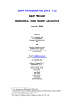
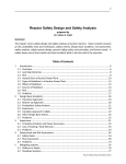
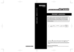
1
US008280696B1
(12) United States Patent
(10) Patent N0.:
(45) Date of Patent:
Aarstein et a].
(54)
METHOD FOR COMPUTER AIDED DESIGN
OF CONDUIT
US 8,280,696 B1
Oct. 2, 2012
MIP’s CoCreate Blog, “SpaceCable 2006 is releasedilntroducing
the next generation of harness design and manufacturing”, retrieved
from http://my.opera.com/cocreate/blog/show.dml/236850 on Dec.
(75) Inventors: Jon Andreas Aarstein, Oslo (NO);
Knut Magnus Ekeberg, Oslo (NO)
(73) Assignee: Ultra Deep, LLC, Houston, TX (US)
(*)
Notice:
3, 2008*
Dr. R.H. Knapp et al., “Computer-aided Design of Cables for Optimal
Performance,” 2005, Sea Technology, pp. 1-5.*
Paul G. Cardinal, “An Expert System for Computer Generation of
Cable, Conduit, and Tray Schedules for INdustrial Power and Control
Systems,” 1995, IEEE trans. on Industry Applications, vol. 3 1, No. 1,
Subject to any disclaimer, the term of this
patent is extended or adjusted under 35
pp. 222-228.*
U.S.C. 154(b) by 0 days.
Design”, 1993, IEEE, pp. 1-6.*
John F. Bash, ed.; “Handbook of Oceanographic Winch, Wire, and
Cable Technology”; 2001; National Science Foundation; Table of
Contents, Introduction, and Chapte 2; 142 total pages.*
(21) App1.No.: 12/034,502
D. Patil et al., “Interactive Graphical Database for Undersea Cable
John M. Vlissides et al., “Unidraw: A Framework for Building
(22) Filed:
(51)
(52)
(58)
Feb. 20, 2008
Domain-Speci?c Graphical Editors”, 1990, ACM, pp. 237-268.*
(Continued)
Int. Cl.
G06F 17/50
(2006.01)
US. Cl. ............... .. 703/1; 703/13; 700/98; 700/107
Field of Classi?cation Search ................ .. 703/1, 6,
703/13; 715/769; 345/619
See application ?le for complete search history.
(56)
References Cited
U.S. PATENT DOCUMENTS
4,862,376 A *
5,187,788
5,515,524
5,740,341
5,917,730
5,987,458
A
A
A
A
A
8/1989
* 2/1993
*
5/1996
* 4/1998
* 6/1999
* 11/1999
6,272,387 B1*
8/2001
Ferriter et al. .............. .. 700/107
Marmelstein
Lynch et al. .
Oota et al.
Rittie et a1.
Anderson et al.
Yoon .......... ..
6,493,679 B1 *
12/2002 Rappaport eta .
6,839,642
7,103,434 B2 *
9/2006
1/2005 Kawakita
Chernyak et a1.
7,107,197 B1 *
9/2006
7,437,688 B2 *
7,558,705 B1 *
Shropshire .... ..
717/109
703/13
345/420
703/6
707/6
Primary Examiner * Mary C Jacob
(74) Attorney, Agent, or Firm * Buskop Law Group, PC;
Wendy Buskop
(57)
ABSTRACT
A method for computer aided design of conduit comprising:
creating a library of speci?cation information and a library of
drawing characteristics related to a plurality of element types
and bundles. An element type is selected, and an identi?cation
key is calculated for the selected element type, forming a
graphics object. The selecting of element types and the cal
culating of identi?cation keys is repeated, forming an updated
graphics object. Speci?cation information and drawing char
.. 700/83
acteristics are retrieved from the libraries and stored in asso
.. 705/29
ciation with each selected element type. At least two element
.. 702/42
types are selected to form a bundle. An identi?cation bundle
.. 700/98
.. 703/13
10/2008 Graham et al. .
716/119
7/2009 Hughes et al. .................. .. 703/1
OTHER PUBLICATIONS
Huang Zhizhang et al., “Computer-Aided Engineering for CANDU
Projects”, 2005, retrieved from http://canteach.candu.org/library/
key is calculated for the bundle. Selection of element types to
form additional bundles is repeated, calculating identi?cation
bundle keys or each additional bundle, forming an updated
bundle graphics object. Speci?cation information and draw
ing characteristics for the bundles are retrieved and stored in
association with the bundles.
18 Claims, 7 Drawing Sheets
20054410.pdf on Dec. 4, 2008*
Speci?cation ""4021
htfonm?nn
For
Selected
Bundle
44a
US 8,280,696 B1
Page 2
OTHER PUBLICATIONS
J .C. Browne et al., “Graphical Programing for simulation of com
puter systems”, 1985, Proceedings of the 18th annual symposium on
Simulation, pp. 109-126.*
Deborah HiX et al., “Developing User InterfacesiEnsuring Usabil
ity Through Product & Process”, 1993, pp. 57-92.*
Curl, Gilbert, “Mechanical Design Automation in IBM
Poughkeepsie”, 18th Design Automation Conference, paper 10.2,
1981 .*
Simmons et al, “The Application ofVirtual Reality to Tasks in Manu
facturing and Assembly Engineering”, KSME International Journal,
vol. 12, No. 1, pp. 1-11, 1998*
Holbrook Enterprises, WireCAD, Version 3.2, User Manual, 2000
2004*
Park et a1, “Computational Support for Concurrent Engineering of
Cable Harnesses”, CDR Technical Report No. 19920219, Feb. 15,
1992*
* cited by examiner
US. Patent
00. 2, 2012
Sheet 1 of7
US 8,280,696 B1
00.0\95
532D E0%0$52m
o2
N2
5M@02 3o250
2EDGE
020E05$\52m0 mm25E\0&80.5280m 2:E0\52H50,
@mo5E80:05205%3 0E@5023Nm,5\
5E@0%0832Nm05\
0E92530Fm.$\5
@.550382050.095 m20 5iE201
@.520 2850
2
“2w50E@B3N5w \ B20“E25%1
20 8 205 8 205 @M0250325 205 20 5 205
mow\
mom\
@065E80205.058 0E 5206
I
new\
520 .“; 520 83 520 83 @.c52o0?mu5Eam 025 5m03 520 8 502.:83m502 50 8 2805EB802 50 .2
5E0820m, RE052P09
@mo50002050.5:
E
B5050E8233Q50.E2:0U5 50@2E 3.2508 “; “[email protected]%052
,025EE08.502963m0,5 25E0@:2850?2
50@2 3“502
US. Patent
0a. 2, 2012
Sheet 2 of7
Selected
Element
Type
1-621
N hi i
US 8,280,696 B1
US. Patent
0a. 2, 2012
Sheet 3 of7
US 8,280,696 B1
Figure 3
Speci?na?nn “an
hi?lnim?nn
25b
‘3'
For
Selected
§ ,1 b
Element
A" *
Types
26¢
76“
12a
23/“
230
US. Patent
0a. 2, 2012
Sheet 4 of7
US 8,280,696 B1
wEDGE
@Nm.\
owm\
oumip?g
vQ5aEcuMQmE
Em0B692¢S0,w
258 0
EE53052
HE0E5mgmg2H5xQ0ob/\EmQE
caotuwge?“m
(m
vE0ac6(u92p0m$o
cnougm?wi
PE0gb0E5o2P0/m
cseow?ag“m
US. Patent
Oct. 2, 2012
Sheet 5 of7
US 8,280,696 B1
Figure 7
1%.?
Speci?na?nn
J
hi?lma?nn ‘PH-ma
For
Selected
Bundle
44a
US 8,280,696 B1
1
2
METHOD FOR COMPUTER AIDED DESIGN
OF CONDUIT
?uid such as HW540, annulus tubes, such as 1/2 inch duplex
carrying ?uids that leak from a riser or from casing surround
ing a Well. Conduits can further include polymeric tubes, such
as nylon tubes carrying ?uids or gasses or gaseous vapors
FIELD
Which leak from a Well, ?exible conduit, or graphite compos
ite tubes carrying hydrocarbon ?uids. Conduits can also
include communication media, such as signal, coaxial, tele
phone, ?ber optic cable, or combinations thereof, such as
those made by Sumitomo or Coming.
The present embodiments relate to a method for computer
aided design of conduit.
BACKGROUND
The present method provides the advantage of enabling
A need exists for a method that enables custom design of
custom design of conduits, Which can include any number of
umbilicals, electrical signal, and poWer cables, by individuals
that lack specialized computer assisted draWing skills, draft
elements, bundles of elements, super bundles, aggregations
ing skills, or advanced engineering or mathematical abilities.
A further need exists for a method that enables production
ments, and further recursive aggregations.
The present method is easily used to design conduits con
and manipulation of electronic draWings for umbilicals that
depict all parts, angles, and vectors of the umbilicals, e?i
taining non-standard umbilical and/ or conduit element types.
The present method further enables non-standard umbilical
and/or conduit element types to be utiliZed and designed
of bundles and super bundles With or Without additional ele
ciently, enabling nearly instantaneous user operation.
repeatably.
A need also exists for a method that enables design of
umbilicals that is extremely accurate, enabling better and
faster quality control than conventional methods.
20
depicted using the present method. Speci?cation information
and graphics objects for each element, bundle, super bundle,
The present embodiments meet these needs.
or aggregations thereof is readily retrievable using the present
BRIEF DESCRIPTION OF THE DRAWINGS
25
The detailed description Will be better understood in con
junction With the accompanying draWings as folloWs:
FIG. 1 depicts a diagram of an embodiment of a system
useable With the present method.
FIG. 2 depicts a display shoWing a graphics object pro
30
larger aggregations can be performed practically instanta
neously because the speci?cation information is electroni
cally linked to the graphics objects. This is a signi?cant time
saving and money-saving bene?t for umbilical designers.
to three libraries for design of a speci?c umbilical. By linking
FIG. 3 depicts a display shoWing multiple graphics objects
produced using the present method.
35
FIG. 5 depicts a display shoWing a bundle graphics object
produced using the present method.
FIG. 6 depicts a display shoWing multiple bundle graphics
objects produced using the present method.
FIG. 7 depicts a diagram of an embodiment of stored data
method.
Technical and/or cost calculations relating to bundles and
The present method involves the use of at least tWo and up
duced using the present method.
FIG. 4 depicts a diagram of an embodiment of stored data
useable With the present method.
For example, an umbilical containing tWo electrical quads,
eight l/2-inch tubes, and one l-inch tube can be quickly
to these libraries and using a graphic object formation meth
odology, a designer can specify a speci?c length for a
uniquely designed umbilical and obtain quickly a list of com
ponents, raW materials, and manufacturing costs, to deter
mine overall cost for manufacture of the umbilical or conduit,
using only ten percent or less of the time currently required
using conventional hand-draWn techniques for umbilicals and
40
other conduits. The present method uniquely enables a list of
raW materials, parts, and other costs for a conduit to be gen
erated simultaneously When designing an umbilical or similar
relating to bundles useable With the present method.
The present embodiments are detailed beloW With refer
ence to the listed Figures.
conduit.
The method provides tremendous versatility in the design
DETAILED DESCRIPTION OF THE
EMBODIMENTS
45
process by offering a customer more than one option With
more than one set of costs for each umbilical design, practi
cally simultaneously. The method enables a customer to
evaluate several designs and thereby choose the most cost
Before explaining the present apparatus in detail, it is to be
understood that the apparatus is not limited to the particular
optimiZing option in the manufacturing process, and thereby
embodiments and that it can be practiced or carried out in
various Ways.
The present embodiments relate to a method for computer
aided design of conduits. A conduit can include an umbilical,
a tubular polymer casing, a tubular laminate casing such as a
50
be more competitive in the industry.
polymer over metal, and other similar conduits, With or With
out coatings, and optionally containing additional tubes or
metal With cathodic protection. An example of such a conduit
can be an umbilical for the Helix-Phoenix project, made by
Parker Cabett of Houston, Tex.
55
information for a conduit, bundle, or larger aggregation, to be
simply and ef?ciently modi?ed and stored in association With
their related graphics objects, through use of identi?cation
keys that are unique to each stored element type, bundle, or
Conduits can contain electrical cables, such as copper elec
Further, the present method enables default speci?cation
larger aggregation.
The present method can thereby be used to design unique
60
trical Wiring, signal cables, such as those made by Geospace
of the United States, NSW of Germany, or Nexans NorWay of
NorWay, or single core, tWo -core, three-core, or multiple-core
cables, such as those made by the same manufacturers. Con
duits can also contain gas carrying tubes, including natural
gas carrying tubes, such as six-inch ?exible tubes, ?uid car
rying tubes, such as 1/2 inch superduplex carrying a hydraulic
custom bundles that can be saved for easy and rapid retrieval.
The modi?cation of speci?cation information enables a user
to see the impact of a change of speci?cation information in
multiple mechanical characteristics, costs, and other areas.
For example, a user can change the material of a ?uid carrying
tube, and vieW updated mechanical and cost-related charac
teristics in response to the change.
65
The present method is simple to operate and can be per
formed by individuals Who lack computer assisted draWing
skills, engineering, calculus, or higher math skills, or drafting
US 8,280,696 B1
3
4
skills. No draftsman or manual drafting is required to design
conduits using the present method. No manual engineering or
mathematical calculations are required to provide mechanical
speci?cations, as the present method incorporates use of soft
Ware that performs calculations to provide mechanical prop
erties of a design. The present method thereby conserves time
In an embodiment, the library of speci?cation information
could be an updatable list, database, array, or similar compi
lation of information.
For example, When an element type is depicted using the
present method, it is originally assigned default speci?cation
information from the library of speci?cation information. If
modi?ed speci?cation information is input by a user, the
and costs related to labor, as Well as time and costs related to
element type can be stored in association With the modi?ed
the drafting process.
The present method provides the bene?t of increased e?i
ciency over conventional methods by providing rapid elec
tronic draWing and design of umbilicals and other conduits,
Which are typically draWn by hand. Manipulation of draWings
can be performed simply and quickly, by users With little
speci?cation information, and the element type With modi?ed
speci?cation information can be retrieved for future use.
The term “element type” can refer to any tube, sheath, tape,
Wire, strand, armor, or similar element able to be used in a
conduit. Element types can include a metal tube having an
inner diameter raging from 0.05 inches to 42 inches, an
specialiZed training, further enhancing the ef?ciency of the
present method.
Through use of menu-based softWare Which provides
mechanical properties for conduit designs, the present
method enables very rapid, nearly instantaneous user opera
tion. The softWare also displays integrated calculations and
extruded polymer sheath applied around tubes or bundles of
element types, a reinforced nylon tape With or Without an
adhesive, a ?at armor Wire, such as Wire made by DrahtWerk
of Germany, or a round armor Wire, such as a Wire made by
Bekaert of Belgium.
20
draWings on the same screen as elements related to the cal
culations, further enhancing the ef?ciency and ease of use of
the present method.
The present method enables production of a full, detailed
representation of each part of a conduit, With calculations that
account for three dimensions, shoWing all angles, vectors,
of l millimeter, bundles of 2 to 20 individual strands having a
diameter of 0.0147 inches, ?ber optic strands, such as those
made by DoW Corning, Woven aluminum Wire, or a pressure
25
include one or more polymeric strands, such as polypropy
lene, polyethylene, or polyaramide strands.
30
Element types can also include shaped ?llers, Which can
include round ?llers or ?llers having other shapes used to ?ll
gaps betWeen elements in a bundle to provide a rounder
cross-sectional shape to the bundle.
35
bundle can have speci?cation information independent of the
speci?cation information of the individual element types con
and Waste of materials and resources.
The present method enables engineers, designers, and
other users to create draWings in the same manner in Which a
conduit is createdifrom the center to the outside. This ben
e?t enhances the e?iciency and accuracy of the design pro
The term “bundle” refers to a group of element types. A
cess by alloWing a conduit to be depicted in the same manner
and order that an umbilical engineer or designer Would con
ceptualiZe the conduit.
Through the production of electronic draWings, the present
tained Within the bundle. One or more items of speci?cation
information for the bundle can be determined using the speci
?cation information of the individual element types Within
40
method reduces the errors that can occur in the manual draft
conventional methods. The present method can produce mul
tiple umbilicals and other conduits in a single day, With a
individual masses of each individual element type Within the
45
bundle, While the pitch angle of the bundle could be a default
value obtained from the library of speci?cation information.
The library of speci?cation information can include ele
ment dimensions, such as lengths and diameters, or element
properties, Which can include mechanical properties such as
50
mass, elasticity, yield strength, magnetic properties, heat
rials. Conventional umbilical design methods are typically
limited to design of a single umbilical in a day, While the
present method can produce a single umbilical in as little as
ten minutes.
The present method incorporates use of softWare that can
interface With other softWare packages to form modules and
transfer properties, conductivity, or permeability. The library
larger integrated packages having multiple features. The soft
of speci?cation information can further include element
material properties, such as insulation, element electrical
properties, such as a dielectric constant, bundle dimensions,
Ware can act as an input ?le for other engineering and design
softWare programs, such as AbaqusTM, oWned by Simulia,
that can incorporate the calculations and features of the con
55
duit designed using the present method.
bundle properties, bundle electrical properties, and combina
tions thereof.
Dimensions and properties can include inner diameter,
outer diameter, Wall thickness, material density, a name or
description of an element or bundle, a modulus of elasticity,
Additionally, the softWare can be secured, such as by using
encryption or similar measures, to prevent terrorism, indus
trial espionage, and similar di?iculties.
The present method includes creating a library of speci?
the bundle. One or more items of speci?cation information
for the bundle could also be determined independent of the
speci?cation information of the individual element types. For
example, the mass of a bundle could be determined using the
ing process, enabling better and faster quality control than
minimum of error, and a minimum of Wasted time and mate
armor, Which is used Within an interior of a ?exible riser used
in a subsea oil Well, such as those made by Wellstream,
Technip, or NKT of Denmark. Element types can further
and parts of a conduit, Which enables more accurate raW
material calculation for creation of conduits than conven
tional methods. This bene?t of the present method not only
conserves time and costs, but also reduces the consumption
Element types can also include electrical strands, such as
an individual strand of copper Wire having an outer diameter
60
an element or bundle mass per unit length, a material ultimate
cation information related to each of a plurality of element
tensile strength, a material yield strength, content of a tube,
types and each of a plurality of bundles. The library of speci
pressure and temperature speci?cations including melting
points, conductivity, lay length, lay angle, and other similar
?cation information can be coded as a table Within a softWare
dimensions and properties.
tool useable to perform the present method, avoiding the need
for use of a separate database or application and alloWing
faster retrieval of the speci?cation information than other
methods.
65
The present method also includes creating a library of
draWing characteristics related to each of the plurality of
element types and each of the plurality of bundles. DraWing
US 8,280,696 B1
5
6
characteristics can include shading, such as to indicate thick
ness, cross hatching, such as to indicate metal or another
material, color, such as black to indicate the Wall of a tube and
0.75 inches, having a thin polymer sleeve, could be depicted
as a black circle With a thick border, encircled by a yelloW
circle With a thin border.
A selected ?at armor Wire could be depicted as a colored
yelloW to indicate a sheath surrounding the tube, and orien
tation, Which can include the position of an element type and
the direction in Which an element type faces.
The library of draWing characteristics can be coded as a
table Within the software tool useable to perform the present
rectangle having a length and Width proportional to the
dimensions of the represented ?at armor Wire. A selected
shaped ?ller could be depicted as a shape approximating the
shape of the selected shaped ?ller, having cross hatching
representing the material of the shaped ?ller.
The present method includes repeating the selecting of
element types and the calculating of identi?cation keys for
each selected element type, forming an updated graphics
object With each repetition. The updated graphics object can
method. It is also contemplated that the library of draWing
characteristics could be part of a separate application, list,
database, array, or other compilation of information.
It is contemplated that selected element types are originally
assigned default draWing characteristics from the library of
draWing characteristics and default speci?cation information
depict any number of selected element types, each located at
the respective element insertion point at Which the selected
element types Were positioned.
Speci?cation information for each selected element type is
from the library of speci?cation. However, a user can input
modi?ed draWing characteristics and/or modi?ed speci?ca
tion information, Which can be stored in association With the
element type, enabling the element type With modi?ed speci
?cation information and/or draWing characteristics to be
20
retrieved from the library of speci?cation information, form
ing retrieved speci?cation information. The retrieved speci
retrieved for future use.
?cation information is then stored in association With the
An element type is then selected from an element type
menu, forming a selected element type, such as by using a
mouse, keyboard, or other input device. The element type
selected element types using each element type’s respective
identi?cation key.
menu can include a drop-doWn menu, a tool-strip menu, or a 25
In an embodiment, the retrieved speci?cation information
can be replaced With other speci?cation information, such as
similar type of menu that lists sorted or unsorted element
speci?cation information provided by user entry, by a soft
types and other functions of the softWare tool used to perform
the present method.
The element type is positioned at an element insertion
point. The term “element insertion point” refers to a position
Ware program, or combinations thereof. It is contemplated
that a user can modify one or more parametrics of the element
type to form a modi?ed element. The replacement speci?ca
30
indenti?ed by a user on a draWing page of the softWare tool
NeW parametrics can simultaneously and automatically be
and the registration of the element type, such as by right
clicking the softWare With a mouse. An element insertion
point can be any location on a display device Within a draWing
area provided by the softWare.
The present method then includes calculating an identi?
cation key for the selected element type, forming a graphics
object. An identi?cation key is created for every element type
selected, and no tWo identi?cation keys are the same. The
identi?cation keys are used to track each selected element
calculated for one or more element types, bundles, or combi
35
nations thereof, such as by use of a softWare program. Para
metrics of all element types, bundles, or combinations thereof
that are connected to the modi?ed element, bundle, or com
binations thereof can be simultaneously and automatically
modi?ed to account for the neW parametrics.
40
The draWing characteristics for each selected element type
are retrieved from the library of draWing characteristics,
forming retrieved draWing characteristics, and stored in asso
ciation With the selected element types. It is contemplated that
45
replaced With other draWing characteristics, such as draWing
type and resulting graphics object. Each identi?cation key is
preferably an integer, such as 10010, but it is contemplated
that identi?cation keys could also include alphanumeric keys,
alphabetic keys, symbol-based identi?ers, and other similar
tion information can then be stored in association With the
modi?ed element.
in an embodiment, the draWing characteristics can be
identi?ers.
The calculation of the identi?cation key can include a
combinations thereof. The replacement draWing characteris
simple and el?cient calculation, such as determining the
value of the largest existing identi?cation key that is an inte
type using the element type’s identi?cation key.
ger, adding one to the integer to obtain a neW identi?cation
characteristics provided by user entry, a softWare program, or
tics can thenbe stored in association With the selected element
50
key, and assigning the neW identi?cation key to the element
type. It is contemplated that, in an embodiment, the calcula
mation Would be retrieved from the library of speci?cation
tion of the identi?cation key can include use of random num
information, indicating an inner diameter of 0.5 inches, a Wall
thickness of 0.25 inches for the metal pipe, and other, similar
ber or alphanumeric generators.
Once an element type has been associated With an identi
55
?cation key, it is contemplated that the selected element type
and any related speci?cation information and/ or draWing
characteristics can be stored in association With the identi?
cation key and retrieved for future use. This feature enables
the present method to alloW previously selected element types
and bundles to be used numerous times, in the design of any
For example, a user may select a metal pipe for transporting
methanol from the element type menu. Speci?cation infor
60
information relating to lay length, pitch angle, and other
speci?cations. LikeWise, draWing characteristics Would be
retrieved, and a black circle approximately 0.5 inches in
diameter With a thick border Would be displayed.
A user could manually enter a larger inner diameter, such
as 1 inch, and this replacement speci?cation information
Would be stored in association With the selected metal pipe.
future conduit, Without recreating the objects, thereby saving
The graphics object representing the pipe could be automati
time and labor.
cally updated to depict a circle having a larger diameter. The
The resulting graphics object for the selected element type
is contemplated to be a cross-sectional depiction of the
selected element type. For example, a selected metal tube
With a Wall thickness of 0.5 inches and an inner diameter of
user could also manually change the thick border to a border
65
having cross hatching for indicating metal, and this draWing
characteristic Would be stored in association With the selected
metal pipe.
US 8,280,696 B1
8
7
In an embodiment, the speci?cation information and draW
object. In an embodiment, this information can be replaced
ing characteristics for one or more selected element types can
With other speci?cation information and draWing character
be retrieved and/or stored simultaneously.
The present method then includes selecting at least tWo
element types of the updated graphics object and forming a
bundle. For example, three graphic representations of electri
istics entered by a user or provided by a softWare program.
Selection of tWo or more updated bundle graphics objects
and calculation of identi?cation super bundle keys can be
repeated, forming an updated super bundle graphics object
With each repetition.
The retrieved speci?cation information and draWing char
cal Wires could be selected to be formed into a bundle using
the softWare tool used to perform the present method.
The bundle is positioned at a bundle insertion point, Which
can be any selected point Within the draWing page of the
softWare tool indicated by the registration of the bundle, such
as by right clicking the software tool With a mouse.
An identi?cation bundle key is calculated for the bundle.
The aggregation of bundles, super bundles, or combina
tions thereof can be repeated to form further aggregations.
Aggregations of these further aggregations can also be
The identi?cation bundle key can be calculated in the same
formed as graphics objects.
acteristics can then be stored in association With the updated
super bundle graphics object.
Graphics objects can be formed representing aggregations
manner as the identi?cation key relating to one or more ele
ment types, such as by adding one to the largest existing
of at least tWo members of the group consisting of: an element
type, a bundle, a super bundle, other aggregations, and com
binations thereof.
identi?cation key for either an element type or a bundle.
Speci?cation information and draWing characteristics for
the bundle can be simultaneously retrieved from the library of
speci?cation information and the library of draWing charac
teristics, respectively, to form a bundle graphics object.
In an embodiment, the speci?cation information, draWing
20
In an embodiment, it is contemplated that elements,
bundles, super bundles, and other aggregations can be
removed from graphics objects and updated graphics objects.
For example, a user could select a graphics object represent
ing an element type and delete the graphics object. A user
characteristics, or combinations thereof can be modi?ed,
such as by user entry or a softWare program. The modi?ed
nations thereof can then be stored in association With the
could also remove one or more selected element types from a
bundle, one or more bundles from a super bundle, or delete
entire bundles or super bundles.
bundle using the bundle identi?cation key.
A bundle graphics object is contemplated to depict each
include the step of adding element types to the element type
speci?cation information, draWing characteristics, or combi
individual element type contained Within the bundle, in close
proximity, With a ?rst circle touching the edge of at least one
25
In a contemplated embodiment, the present method can
30
Speci?cation information and draWing characteristics relat
of the depicted element types, indicating a possible outer
diameter of the bundle, and a second circle betWeen each of
the element types, indicating a possible inner diameter of the
bundle.
The selecting of element types from the updated graphics
object is repeated, forming additional bundles, for Which
menu. For example, a neW type of ?exible tubing for use in
conduits not included in the element type menu can be added.
ing to the neW element type can also be added to the library of
speci?cation information and the library of draWing charac
teristics, respectively.
35
It is contemplated that, in an embodiment, speci?cation
information can be added or removed from the library of
additional identi?cation bundle keys are calculated. An
speci?cation information, and that draWing characteristics
updated bundle graphics object is formed after each repeti
tion. The updated bundle graphics object can include depic
can be added or removed from the library of draWing charac
teristics.
In an embodiment, the present method can also include
tions of multiple bundles that are formed, or modi?ed depic
tions of existing bundle graphics objects, such as When one or
40
creating a library of costs relating to each of the plurality of
more elements are selected to be added to or removed from
element types. Part cost information, raW material cost infor
existing bundle graphics objects.
mation, manufacturing cost information, or combinations
thereof can be retrieved from the library of costs, simulta
neous With the retrieval of speci?cation information and/or
It is contemplated that a user can modify one or more
parametrics of the bundle. NeW parametrics can simulta
45
draWing characteristics from the respective libraries.
neously and automatically be calculated for the bundles, such
It is also contemplated that information can be added or
as by use of a softWare program. Parametrics of all element
types, bundles, super bundles, larger aggregations, or combi
nations thereof that are connected to the modi?ed bundle can
be simultaneously and automatically modi?ed to account for
50
the neW parametrics.
In an embodiment, the present method can include the
formation of recursive aggregations of multiple bundles,
aggregations of these aggregations, and further aggregations,
as needed, to design conduits containing large numbers of
design process.
The present method can further include the step of printing
55
aggregated bundles and groups of bundles.
one or more graphics objects, printing a calculation report,
printing a material selection report, saving one or more graph
ics objects, connecting to another softWare program, or com
binations thereof, once a graphics object is formed.
Use of the present method is illustrated through the folloW
TWo or more updated bundle graphics objects can be
selected to form a super bundle, Which can be positioned at a
ing example:
super bundle insertion point.
An identi?cation super bundle key can be calculated for
each super bundle. The identi?cation super bundle key can be
removed from the library of costs. Through use of the library
of costs, the present method can enable accurate quantities of
required parts and/or materials and related costs to be calcu
lated nearly instantaneously, simultaneous With the conduit
60
A user that Wishes to design a conduit for carrying electri
cal cable can provide speci?cations for an umbilical to be
calculated in the same manner as identi?cation keys for ele
produced. For example, the user may specify that the umbili
ment types and/or bundles.
cal must contain 2 electrical quads, 8 metal tubes With a
diameter of 0.5 inches, and 1 metal tube With a diameter of l .0
inch. The user can also specify desired pressure ratings for the
Speci?cation information and draWing characteristics for
the super bundle are simultaneously retrieved from the library
of speci?cation information and the library of draWing char
acteristics, respectively, forming a super bundle graphics
65
metal tubes and voltage and poWer ratings for the electrical
quads.
US 8,280,696 B1
10
The graphics object representing the bundle canbe inserted
Using international standards and/or codes, the appropriate
at any desired insertion point.
Wall thickness for the metal tubes required to meet the user’ s
speci?cations can be determined. The copper cross-section
area and insulation thickness required to meet the user’s
A user can add any number of element types and form any
number of bundles, as needed to design the desired conduit.
Further, multiple bundles can be selected and formed into
super bundles. Multiple super bundles can be selected and
formed into larger aggregations, Which can in turn be formed
into even larger aggregations. An unlimited number of aggre
gations can be formed, as necessary, to design a conduit.
speci?cations for the electrical quads can also be determined
using international standards and/or codes.
Pre-coded libraries of speci?cation information and draW
ing characteristics containing programmed default values for
metal tubes and electrical quads are provided for access. The
libraries can be stored on a netWorked server or a similar data
Referring noW to FIG. 1, a diagram of an embodiment of a
storage media for access during the design of the umbilical.
system useable With the present method is shoWn.
FIG. 1 depicts data storage (5), Which can be any type of
data storage medium or combination of data storage media,
including ?xed data storage, such as a computer hard drive,
removable data storage, such as a portable memory stick,
Using a software tool, the user can select a metal tube from
the element type menu, Which can be a drop doWn menu, a
tool-strip menu, or a similar type of menu. A graphics object
depicting the metal tube Will appear alongside a WindoW
displaying default speci?cations for the metal tube obtained
from the library of speci?cation information. The default
diameter of the tube can be 0.5 inches, With a corresponding
Wall thickness.
The user can modify the diameter of the metal tube to 1.0
netWorked data storage, such as a server, and other types of
data storage media.
Data storage (5) is shoWn in communication With a proces
20
sor (6), Which can be any type of processor, such as an IntelTM
or AMDTM processor. The processor (6) could also be a pro
inch and double the default Wall thickness by entering data
cessor Within a cellular telephone, personal digital assistant,
into the WindoW displaying speci?cation information, Which
Will automatically cause the displayed graphics object to
or similar handheld device.
reference neW draWing characteristics from the library of
display (7), Which can be any type of display device, includ
draWing characteristics. The initial graphics object Will be
replaced by a neW graphics object representing the metal tube
The processor (6) is depicted in communication With a
25
cellular telephone, personal digital assistant, or similar hand
having a diameter of 1.0 inch.
The user can position the graphics object anyWhere Within
the draWing WindoW of the display, thereby selecting an ele
ment insertion point.
held device, or other similar displays.
A user (9) is depicted in communication With the processor
(6), using an input device (13), Which can include one or more
30
A identi?cation key, such as 43567, relating to the 1.0-inch
diameter metal tube is calculated by the software tool, Which
checks all existing identi?cation keys and generates an iden
ti?cation key that is not yet used by adding one to the largest
existing identi?cation key. This identi?cation key is then
ing a computer monitor, a projection screen, a display of a
keyboards, keypads, touch screens, a mouse, voice recogni
tion softWare, and/or other types of input devices. The user (9)
is contemplated to provide input to the processor (6) in
response to the output transmitted from the processor (6) to
the display (7).
35
The display (7) is depicted displaying an element type
associated With the 1.0-inch diameter metal tube.
The user can then select eight additional metal tubes from
menu (20), containing a ?rst element type (1811), a second
element type (18b), and a third element type (180), for selec
the element type menu, adjusting the speci?cation informa
tion by the user (9). For example, the ?rst element type (1811)
could be a metal pipe, the second element type (18b) could be
an electrical Wire, and the third element type (180), could be
tion as needed. The user can also select tWo previously gen
erated electrical quads inserted from a previous ?le, also
adjusting the speci?cation information for each electrical
40
a polymeric tube.
Data storage (5) is shoWn containing a library of speci?
quad, if necessary. Each neW element type can be inserted at
any desired element insertion point.
The user can then select each of the metal tubes and both
electrical quads, such as by clicking on each element With a
mouse, then form a bundle, such as by right-clicking the
softWare WindoW and selecting that a bundle be formed using
45
speci?cation information (3011), a second element type speci
?cation information (30b), and a third element type speci?
a menu.
A graphics image representing a bundle containing the 8
0.5-inch diameter metal tubes, the 1 1.0-inch metal tube, and
50
the 2 electrical quads Will appear alongside a WindoW dis
playing speci?cation information for the bundle, such as the
cation information (300).
It is contemplated that the ?rst element type speci?cation
information (3011) relates to the ?rst element type (1811), the
second element type speci?cation information (30b) relates
to the second element type (18b), and the third element type
speci?cation information (300) relates to the third element
lay angle and lay length of the bundle. Some elements of this
speci?cation information can be determined by the softWare
using the speci?cation information for each individual ele
ment type Within the bundle. Other elements of the speci?
cation information relating to a plurality of element types
(10). The library of speci?cation information relating to a
plurality of element types (10) contains a ?rst element type
55
type (180). For example, the ?rst element type (1811) could
have ?rst element type speci?cation information (3011) that
indicates a default outer diameter of 0.5 inches, a Wall thick
cation information for the bundle can be default settings
ness of 0.25 inches, a lay angle of 12 degrees, and a lay length
retrieved from the library of speci?cation information. Items
of speci?cation information for the bundle can be changed by
of 634.995 millimeters.
a user, such as by entering a neW lay angle, and all other items
60
of speci?cation information can be automatically updated by
the softWare to account for the change input by the user.
The processor is then instructed to create an identi?cation
bundle key for the bundle, Which can be obtained by adding
one to the largest existing identi?cation key, yielding the
identi?cation bundle key 45368. The identi?cation bundle
key is then stored in association With the bundle.
65
Data storage (5) is also shoWn containing a library of
draWing characteristics relating to a plurality of element types
(12). The library of draWing characteristics relating to a plu
rality of element types (12) contains a ?rst element type
draWing characteristic (3211), a second element type draWing
characteristic (32b), and a third element type draWing char
acteristic (320).
It is contemplated that the ?rst element type draWing char
acteristic (32a) relates to the ?rst element type (1811), the
US 8,280,696 B1
11
12
second element type drawing characteristic (32b) relates to
the second element type (18b), and the third element type
drawing characteristic (32c) relates to the third element type
(180). For example, the ?rst element type (1811) could have
?rst element type drawing characteristic (3211) that indicates a
updated graphics object (28), which is formed after each
additional element type is selected by a user. The updated
graphics object (28) includes the individual graphics objects
for each selected element type.
The display (7) depicts the ?rst graphics object (26a) at the
?rst element type insertion point (2211), representing the ?rst
element type (18a, depicted in FIG. 1).
A second graphics object (26b) is depicted at a second
element type insertion point (22b), representing the second
element type (18b, depicted in FIG. 1). It is contemplated that
the processor can produce the second graphics object using
default drawing that includes a black circle having a diameter
of 0.5 inches and a line width of 0.1 inches.
Data storage (5) is further shown containing a library of
speci?cation information related to a plurality of bundles
(14), which includes a ?rst bundle speci?cation information
(4011), a second bundle speci?cation information (40b), and a
the drawing characteristics relating to the second element
type. The second graphics object (26b) is depicted as a circle
having four round internal components, representing an elec
third bundle speci?cation information (400). The bundle
speci?cation information (40a-c) is contemplated to relate to
one or more bundles that can be formed from element types.
trical quad.
Data storage (5) also contains a library of drawing charac
teristics related to a plurality of bundles (16). The library of
drawing characteristics related to a plurality of bundles (16),
includes a ?rst bundle drawing characteristic (4211), a second
bundle drawing characteristic (42b), and a third bundle draw
ing characteristic (420). The bundle drawing characteristics
A third graphics object (260) is depicted at a third element
type insertion point (220), representing the third element type
(180, depicted in FIG. 1). It is contemplated that the processor
can produce the third graphics object using the drawing char
20
acteristics relating to the third element type. The third graph
(42a-c) are contemplated to relate to one or more bundles
ics object is depicted as a circle representing a ?exible tube
formed from element types.
for carrying ?uid.
The speci?cation information (30) relating to any of the
Data storage (5) is further shown containing computer
instructions (11), which are contemplated to instruct the pro
cessor (6) to accept user input to replace speci?cation infor
mation and drawing characteristics associated with an ele
25
(7) simultaneous with the graphics objects (26a-c).
ment type or bundle, to produce graphics objects representing
element types and bundles, to calculate identi?cation keys,
and to store identi?cation keys associated with element types
and/or bundles and related speci?cation information and
drawing characteristics. The computer instructions (11) can
It is contemplated that a user can modify the speci?cation
information (3 0) or drawing characteristics for any of the
graphics objects (26a-c).
30
can be instructed to calculate an identi?cation key for each
mation by a user.
35
exemplary display screen produced using the present method.
It is contemplated that after a user selects an element type
(18a, depicted in FIG. 1) from the element type menu, the
computer instructions in the data storage can instruct the
processor to generate a ?rst graphics object (2611) using the
?rst element type drawing characteristics (32a, depicted in
FIG. 1).
The ?rst graphics object (26a) is shown as an inner circle,
representing a metal pipe, encircled by an outer circle, repre
senting a protective sleeve for the metal pipe.
40
45
?cation information (3011) related to the selected element
type
It is contemplated that the user can enter replacement
50
include data retrieved from the library of speci?cation infor
mation or the library of drawing characteristics, respectively,
55
characteristics (32b) that relate to the second element type
60
The ?rst graphics object (26a) is positioned at a ?rst ele
ment type insertion point (2211). It is contemplated that a user
can move the ?rst graphics object (26a) to any other position
from the element type menu. The display (7) depicts an
(18b, depicted in FIG. 1). It is contemplated that the second
element type speci?cation information (30b), the second ele
ment type drawing characteristics (32b), or combinations
thereof can include data retrieved from the library of speci?
cation information or the library of drawing characteristics,
within the display (7).
Referring now to FIG. 3, an exemplary display (7) is
or data inserted by a user.
A second identi?cation key (24b) is depicted stored in data
storage (5) in association with the second element type speci
?cation information (30b) and second element type drawing
characteristics of the ?rst graphics object (2611), such as by
depicted after a user has selected additional element types
ated for the element type using the present method can store
the modi?ed speci?cation information for that element type
in association with the identi?cation key.
A ?rst identi?cation key (2411) is depicted stored in data
storage (5) in association with the ?rst element type speci?
cation information (3011) and ?rst element type drawing char
acteristics (32a) that relate to the ?rst element type (18a,
depicted in FIG. 1). It is contemplated that the ?rst element
drawing characteristics (3211), or combinations thereof can
It is further contemplated that the user can alter the drawing
changing the color or thickness of the lines, adding or remov
ing cross hatching, or changing other similar characteristics.
vidual element types to be tracked and referenced. For
example, if a user selects an element type, then replaces the
speci?cation information related to that element type with
type speci?cation information (3011), the ?rst element type
can cause the computer instructions to modify the ?rst graph
ics object (2611). For example, if the user were to change the
inner diameter of the speci?cation information (3011) from 0.5
inches to 1.0 inch, the ?rst graphics object (26a) could be
automatically modi?ed by the processor to appear larger.
selected element type. Each identi?cation key is stored in the
data storage (5) in association with the speci?cation informa
tion and drawing characteristics for the element type.
It is contemplated that the identi?cation keys allow indi
other speci?cation information, the identi?cation key gener
The display (7) also displays the ?rst element type speci
speci?cation information to replace the displayed speci?ca
tion information (3011). Entered replacement speci?cation
Referring now to FIG. 4, a diagram depicting exemplary
contents of the data storage (5) is shown.
After forming a graphics object for each selected element
type, it is contemplated that the processor (depicted in FIG. 1)
also calculate speci?cation information responsive to the for
mation of bundles or the replacement of speci?cation infor
Referring now to FIG. 2, a display (7) is shown depicting an
?rst element type, the second element type, the third element
type, or combinations thereof, can be displayed on the display
65
respectively, or data inserted by a user.
A third identi?cation key (240) is depicted stored in data
storage (5) in association with the third element type speci?
US 8,280,696 B1
13
14
cation information (3 0c) and third element type drawing char
acteristics (320) that relate to the third element type (180,
depicted in FIG. 1). It is contemplated that the third element
type speci?cation information (300), the third element type
bundle drawing characteristics (42b) from the library of
drawing characteristics relating to bundles (16, depicted in
FIG. 1).
The second bundle graphics object (44b) is depicted as an
identical bundle, containing identical element types to the
drawing characteristics (320), or combinations thereof can
bundle represented by the ?rst bundle graphics object (4411),
include data retrieved from the library of speci?cation infor
mation or the library of drawing characteristics, respectively,
however, it is contemplated that any types of bundles contain
ing identical or different element types can be displayed and
or data inserted by a user.
represented with bundle graphics objects.
Each identi?cation key could also be stored with the asso
ciated graphics object, element type, and other similar infor
mation relating to the associated element type.
Referring now to FIG. 5, an exemplary display (7) is
depicted after a user has selected displayed graphics objects
The display (7) can also depict bundle speci?cation infor
mation (40) relating to one or both of the displayed bundles.
It is contemplated that the user can replace any items of the
speci?cation information (40), and/or any drawing character
instructions in the data storage can instruct the processor to
istics of the ?rst bundle graphics object (4411) or the second
bundle graphics object (44b), or combinations thereof.
Referring now to FIG. 7, a diagram depicting exemplary
contents of the data storage (5) is shown.
aggregate the selected element types into a bundle and display
a bundle graphics object.
contemplated that the processor (depicted in FIG. 1) can be
for three element types and formed a bundle.
It is contemplated that after a user selects two or more
graphics objects representing element types, computer
The display (7) depicts a ?rst bundle graphics object (4411)
After forming one or more bundles of element types, it is
20
storage (5) in association with the speci?cation information
and drawing characteristics for the bundle.
It is contemplated that the identi?cation bundle keys allow
display (7) by the user.
The ?rst bundle graphics object (44a) is shown as an outer
circle, touching the edge of one of the individual graphics
25
objects for an element type, indicating a possible outer diam
eter of the bundle. The ?rst bundle graphics object (4411) also
includes an inner circle between each of the graphics objects
The drawing characteristics of the ?rst bundle graphics
object (44a) can be determined using the ?rst bundle drawing
characteristics (4211) from the library of drawing characteris
tics related to bundles (16, depicted in FIG. 1).
The display (7) also displays ?rst bundle speci?cation
information (4011) relating to the bundle. The ?rst bundle
speci?cation information (4011) can be derived from the speci
?cation information relating to each of the individual selected
element types within the bundle, from the library of speci?
cation information related to bundles (14, depicted in FIG. 1),
selects a bundle, then replaces the speci?cation information
related to that bundle with other speci?cation information, the
identi?cation bundle key generated for the bundle using the
30
35
40
It is contemplated that the user can enter replacement
A second identi?cation bundle key (38b) is depicted stored
in data storage (5) in association with the second bundle
45
sented by bundle graphics object (44b, depicted in FIG. 6). It
is contemplated that the second bundle speci?cation informa
tion (40b), the second bundle drawing characteristics (32b),
50
or combinations thereof can include data retrieved from the
library of speci?cation information or the library of drawing
characteristics, respectively, or data inserted by a user.
It is further contemplated that the user can alter the drawing
characteristics of the ?rst bundle graphics object (44a), such
55
A third identi?cation bundle key (380) is depicted stored in
data storage (5) in association with the third bundle speci?
cation information (40c) and third bundle drawing character
istics (420) that can relate to an additional third bundle formed
by a user. It is contemplated that the third bundle speci?cation
information (400), the third bundle drawing characteristics
depicted after a user has selected additional element types
(320), or combinations thereof can include data retrieved
60
representing the additional element types, and formed a sec
ond bundle from the additional element types.
from the library of speci?cation information or the library of
drawing characteristics, respectively, or data inserted by a
user.
The display depicts the ?rst bundle graphics object (4411) at
the ?rst bundle insertion point (3611).
A second bundle graphics object (44b) is depicted at a
second bundle insertion point (3 6b). The second bundle
graphics object (44b) can be produced using the second
speci?cation information (40b) and second bundle drawing
characteristics (42b) that relate to the second bundle repre
calculate a new lay length, mass, and weight for the bundle, as
from the element type menu, selected the graphics objects
that the ?rst bundle speci?cation information (4011), the ?rst
bundle drawing characteristics (3211), or combinations
thereof can include data retrieved from the library of speci?
cation information or the library of drawing characteristics,
respectively, or data inserted by a user.
cation information and/or the ?rst bundle graphics object
(4411). For example, if the user were to change the pitch angle
of the speci?cation information (4011), the processor could
as by changing the color or thickness of the lines, adding or
removing cross hatching, or changing other similar charac
teristics.
Referring now to FIG. 6, an exemplary display (7) is
A ?rst identi?cation bundle key (3811) is depicted stored in
data storage (5) in association with the ?rst bundle speci?ca
tion information (40a) and ?rst bundle drawing characteris
tics (4211) that relate to the ?rst bundle represented by bundle
graphics object (44a, depicted in FIG. 6). It is contemplated
speci?cation information to replace the displayed speci?ca
tion information (4011). Entered replacement speci?cation
well as other speci?cation information, and automatically
display the new lay length, mass, weight, and other informa
tion in the speci?cation information (4011).
present method can store the modi?ed speci?cation informa
tion for that bundle in association with the identi?cation
bundle key.
or combinations thereof.
can cause the computer instructions to modify other speci?
individual bundles to be tracked and referenced in the same
manner as individual element types. For example, if a user
representing element types, indicating a possible inner diam
eter of the bundle.
instructed to calculate an identi?cation bundle key for each
bundle. Each identi?cation bundle key is stored in the data
at a ?rst bundle insertion point (3 6a). The ?rst bundle graph
ics object (4411) can be positioned at any location in the
65
Each identi?cation bundle key could also be stored with the
associated bundle graphics object and other similar informa
tion relating to the associated bundle.
While these embodiments have been described with
emphasis on the embodiments, it should be understood that
US 8,280,696 B1
15
16
Within the scope of the appended claims, the embodiments
might be practiced other than as speci?cally described herein.
With the processor, Wherein the additional speci?cation and
additional draWing characteristic are displayed on the display
screen.
5. The method of claim 1, Wherein a bundle identi?cation
What is claimed is:
1. A method for computer aided design of conduit com
key is associated With the bundled graphic object.
6. The method of claim 1, further comprising linking a
plurality of speci?cations to the element type stored in the
database of speci?cation information.
7. The method of claim 6, Wherein the plurality of speci?
cations linked to the element type comprises element type
prising:
a. selecting a ?rst element type from an element type menu,
Wherein the ?rst element type is linked With a speci?ca
tion stored in a database of speci?cation information and
a draWing characteristic stored in a database of draWing
dimensions, element type properties, element type material
properties, and element type electrical properties.
characteristics on a data storage in communication With
a processor, and Wherein the speci?cation and draWing
8. The method of claim 1, Wherein the speci?cation com
prises at least one of: element type dimensions, element type
characteristic are displayed on a display screen;
b. generating a ?rst graphic object depicting the ?rst ele
properties, element type material properties, and element
type electrical properties.
ment type on the display screen at a point of input,
Wherein the ?rst graphic object is automatically gener
ated using the speci?cation and the draWing character
istic linked to the ?rst element type;
. selecting a second element type from the element type
menu, Wherein the second element type is linked With a
20
speci?cation stored in the database of speci?cation
information and a draWing characteristic stored in the
database of draWing characteristics on the data storage
in communication With the processor, and Wherein the
speci?cation and draWing characteristic are displayed
25
on the display screen;
d. generating a second graphic object depicting the second
element type on the display screen at a point of input,
Wherein the second graphic object is automatically gen
erated using the speci?cation and the draWing charac
teristic linked to the second element type;
35
storage to instruct the processor to aggregate the ?rst
element type and the second element type into the
40
the speci?cation information linked to each of the
45
bundled graphic object is formed.
2. The method of claim 1, further comprising changing the
15. The method of claim 1, Wherein the ?rst graphic object
circle, thereby representing a sleeve disposed over a pipe.
16. The method of claim 1, Wherein the display of the
bundled graphic object comprises:
object; and
50
3. The method of claim 1, further comprising changing the
speci?cation linked to the element type and automatically
modifying the graphic object based on the changed speci?
cation, Wherein an identi?cation key is assigned to the
changed speci?cation and stored on the data storage.
4. The method of claim 1, further comprising selecting an
additional element type from the element type menu, Wherein
the additional element type is linked to an additional speci?
cation stored in the database of speci?cation information and
an additional draWing characteristic stored in the database of
draWing characteristics on the data storage in communication
the bundled graphic object.
a. an outer circle touching an edge of the ?rst graphic object
indicating an outer diameter of the bundled graphic
speci?cation linked to the element type, and Wherein the
graphic object is automatically modi?ed based on the
changed speci?cation.
14. The method of claim 1, Wherein the display of the
bundled graphic object comprises a ?rst circle touching an
edge of the ?rst graphic object or the second graphic object
indicating an outer diameter of the bundled graphic object,
and a second circle disposed betWeen the ?rst graphic object
and the second graphic object indicating an inner diameter of
is displayed as an inner circle and Wherein the second graph
ics object is displayed as an outer circle encircling the inner
graphic objects that account for three dimensions, shoW
ing all angles, Vectors, and parts of a conduit and using
the calculations to automatically generate a list of com
ponents, raW materials, and manufacturing costs as the
13. The method of claim 1, Wherein the bundling of the ?rst
graphic object and the second graphic object comprises dis
posing the ?rst graphic object and the second graphic object
Within a sheath.
object and selecting a function from a menu to form a
bundled graphic object; and
f. instantaneously With the aggregating performing calcu
lations using softWare that performs calculations using
at least one of the speci?cation or the draWing characteristic
linked to the element type and calculating a cost associated
With the element type in response to the modi?cation.
12. The method of claim 1, Wherein the element type com
prises a tube, a sheath, a tape, a Wire, a ?ber optic strand, an
armor, a ?ller, or combinations thereof.
30
e. selecting the ?rst graphic object and the second graphic
bundled graphic object, Wherein the bundled graphic
object is formed using computer instructions in the data
9. The method of claim 1, further comprising linking a
plurality of draWing characteristics linked to the element type
stored in the database of draWing characteristics.
10. The method of claim 9, Wherein the plurality of draW
ing characteristics linked to the element type comprises shad
ing, cross hatching, color, and orientation.
11. The method of claim 1, further comprising modifying
55
b. an inner circle disposed betWeen the ?rst graphic object
and the second graphic object, indicating an inner diam
eter of the bundled graphic object.
17. The method of claim 1, further comprising a shaped
?ller ?lling gaps betWeen the ?rst graphic object and the
second graphic object of the bundled graphic object to pro
Vide a round cross-sectional shape to the bundled graphic
object.
60
18. The method of claim 1, Wherein the element type is a
member of the group consisting of: a metal tube, an electrical
quad, an extruded polymer sheath, or combinations thereof.
*
*
*
*
*