Download Digital image projection luminaire systems
Transcript
US 20100201702A1
(19) United States
(12) Patent Application Publication (10) Pub. N0.2 US 2010/0201702 A1
FRANIK et al.
(54)
(43) Pub. Date:
DIGITAL IMAGE PROJECTION LUMINAIRE
Related US. Application Data
SYSTEMS
(75)
Inventors:
Aug. 12, 2010
(60)
Provisional application No. 61/ 149,693, ?led on Feb.
3 2009.
’
Martin FRANIK, Postredni Becva
(CZ); Josefvalchera postredni
Becva (CZ); Pavel Jurik, Postredni
Beeva (CZ)
Publication Classi?cation
(51) Int_ CL
G09G 5/02
(2006.01)
G09G 5/00
(2006.01)
Correspondence Addressi
(52)
us. Cl. ....................................... .. 345/589; 345/661
HEINZ GRETHER PC
G2 Technology Law
P‘O‘ BOX 202858
AUSTIN’ TX 78720 (Us)
(57)
ABSTRACT
The present invention provides improvements to digital imag
ine projection systems and for seamless blending of images
_
projected from a plurality of digital image projectors to create
(73) Asslgnee?
ROBE LIGHTING S-R-O-
(21) Appl. No.:
12/699,620
combined images from multiple projectors Where the user is
provided With independent control of the blend area and of
independent control of image parameters Within said variable
blend area such as brightness, contrast, individual color inten
(22)
Filed:
Feb. 3, 2010
sity and gamma correction.
1lw
1 0»\ I
‘ \4 2
1a
1 0"\_ I
l 0% r
“" \“1 2
"' \"1 2
Patent Application Publication
Aug. 12, 2010 Sheet 1 0f 11
11
10%!
US 2010/0201702 A1
W
\Wu
Ea
10%’
‘M12
FEG?
Patent Application Publication
Aug. 12, 2010 Sheet 2 0f 11
18%!
2a
PEG 2
US 2010/0201702 A1
Patent Application Publication
Aug. 12, 2010 Sheet 3 0f 11
US 2010/0201702 A1
RG8
Output
input
352
Ouiput
H6 3
Patent Application Publication
Aug. 12, 2010 Sheet 4 0f 11
3
2
3
4 4
"4a
\
i
M31
Z 2
3
3
3
3
44
1
4 4
4b
33
Right’criangie
1
23
3
<51
2 2
Z 2
3
2
23
i 1 3
23
is‘) H3
1
i
1
isnsceies triangia
‘\..
3
i1 4
1
4 4
3
2
2
3
2
2“
i 1 33
41
2
3 "Q \.-.
2
i i 3
2,3
1133113
2
41:
2
4 4
3
3
3
2
'E
3
2
3
4 "'l
‘F
i
44
2
Square
3
Z Z
1
2
US 2010/0201702 A1
42
Patent Application Publication
Aug. 12, 2010 Sheet 5 0f 11
US 2010/0201702 A1
Harizantai Mirrcr
51
D
c
Ve::ter:a§
52
A
A
B
Msrrar
53
c
B
B
c
D
54
A
B
A
a
c
9
PEG 5
WW
A A
WM
62
A A
FEE 6
Patent Application Publication
Aug. 12, 2010 Sheet 6 0f 11
US 2010/0201702 A1
29% pixeis
M
V
72%;,
i
i
i
i
I
i
i
768 pixQEs
71Ws:
E r:
1924 pixais
i024- pixeis
W24 pix?s
E324 pixeis
768 pixeis
768 pixeis
73'~\_r
75%;‘
HG 7
Patent Application Publication
85
83%
/
Aug. 12, 2010 Sheet 7 0f 11
US 2010/0201702 A1
Patent Application Publication
Aug. 12, 2010 Sheet 8 0f 11
US 2010/0201702 A1
RG8
Output
input
‘9a
RG8
Output
input
FEG 9
Patent Application Publication
Aug. 12, 2010 Sheet 9 0f 11
US 2010/0201702 A1
110
1 14
112
1 12
1 12
O0
0O
0O
115
\/
j/
114
\/
x/
114
Patent Application Publication
Aug. 12, 2010 Sheet 10 0f 11
US 2010/0201702 A1
‘123
\125
FEGH
Patent Application Publication
Aug. 12, 2010 Sheet 11 0f 11
137 138
I'l’
132
\
‘Il
l
‘I
I
135
133
131'
\
FiG ‘E 2
US 2010/0201702 A1
Aug. 12, 2010
US 2010/0201702 A1
DIGITAL IMAGE PROJECTION LUMINAIRE
SYSTEMS
[0011] FIG. 6 illustrates an embodiment of image mirror
ing in the invention and of a non-?at projection surface;
[0012]
RELATED APPLICATION(S)
[0001] This application is a utility ?ling claiming priority
of provisional application 61/ 149,693 ?led 3 Feb. 2009.
TECHNICAL FIELD OF THE INVENTION
FIG. 7 illustrates an embodiment of re-cutting an
image in the invention;
[0013]
FIG. 8 illustrates an embodiment of a test pattern of
the invention;
[0014]
FIG. 9 illustrates an embodiment of a linear gamma
curve;
[0015]
FIG. 10 illustrates an embodiment of a multi-lumi
[0002] The present invention generally relates to the pro
jection of images and more speci?cally to imaging systems
naire system of the invention;
used for the projection of digital images.
tion in the invention; and
[0016]
[0017]
FIG. 11 illustrates an embodiment of color correla
FIG. 12 illustrates a luminaire With tWo sources.
BACKGROUND OF THE INVENTION
[0003] Projection systems are commonly used in many dif
ferent entertainment and commercial applications. Such
products are commonly used in theatres, television studios,
concerts, theme parks, night clubs and other venues. These
systems may be used to project content from video sources
such as DVD players or video cameras or may project a video
stream that is computer generated. One application for such
devices is as a luminaire Where a video projection system is
used as a light source giving the user full control over the
imagery, color, patterns and light output of the luminaire.
Examples of such a system are the Icon M from Light &
Sound Design and the Digital Spot 7000DT from Robe Light
ing SRO.
DETAILED DESCRIPTION OF THE INVENTION
[0018] Preferred embodiments of the present invention are
illustrated in the FIGUREs, like numerals being used to refer
to like and corresponding parts of the various draWings.
[0019] The present system generally relates to an auto
mated luminaire, speci?cally to a image projection luminaire.
Improvements are disclosed in many areas of image projec
tion luminaire system including but not limited to: picture
blending; gamma curve of the blended edge; Kaleidoscopic
effect; Control of contrast and brightness of the projected
imagesiRGB Scale; Blending of adj acent mirrored images;
Automatic correlation of the colors from LED modules to the
In many cases the imagery used in these projection
colors of the projected images Which are described in greater
detail beloW.
luminaires is produced by a media server. A media server is
usually a computer based system Which alloWs the user to
select a video image from an external library, manipulate and
luminaire system 110. These systems commonly include a
[0004]
distort that image, combine it With other images and output
the completed imagery as a video stream. Examples of some
of the many different manipulations available might include
image rotation & scaling, overlaying multiple images and
color change. The outputs from a plurality of such automated
luminaires may further be tiled or overlaid as the operator
desires in order to produce either a much larger image com
prising tiles from multiple luminaires tiled side by side or a
single brighter image Where identical images from multiple
luminaires are fully overlaid. These media servers may be
[0020]
FIG. 10 illustrates an automated image projection
plurality of automated image projection luminaires 112
Which typically each contain on-board a light source or light
engine (not shoWn), light modulation devices capable of pro
jecting electronic video or still imagery, electric motors
coupled to mechanical drives systems (not shoWn) and con
trol electronics (not shoWn). In addition these luminaires 112
may include mechanical drive system and control electronics
to control the orientation of the central axis (not shoWn) of the
projected light beam output (not shoWn). In addition to being
connected to mains poWer either directly or through a poWer
distribution system (not shoWn), each luminaire is connected
incorporated in the luminaire or they may be separate from
is series or in parallel to data link 114 to one or more control
the luminaire. In either case the media server may serve one or
desks 115. The luminaire system 110 is typically controlled
by an operator through the control desk 115.
multiple luminaires providing such luminaires With signals
Which may contain image data generally in either digital or
analog form. This disclosure provides improvements to
image projecting luminaires.
BRIEF DESCRIPTION OF THE DRAWINGS
[0005] For a more complete understanding of the present
invention and the advantages thereof, reference is noW made
to the folloWing description taken in conjunction With the
accompanying draWings in Which like reference numerals
[0021] Picture Blending
[0022] It is knoWn in prior art systems to provide an overlap
betWeen adjacent tiled images from tWo projection lumi
naires such that the appearance of the join betWeen the tWo
images is minimiZed and as invisible as possible. One image
fades out as the adjacent and overlaid image fades in provid
ing a minimal visible joint betWeen the tWo images. In the
prior art, this overlap or blended edge area is ?xed in the
luminaire and may typically be approximately 5 percent of
indicate like features and Wherein:
[0006] FIG. 1 illustrates an embodiment of picture blend
the total image siZe. HoWever it is almost impossible to get an
invisible joint using a small blending area like this particu
ing in the invention With tWo projection luminaires;
larly With large areas of single color such as a blue sky or sea
or other generally ?at color areas. One aspect of the improved
[0007]
FIG. 2 illustrates an embodiment of picture blend
ing in the invention With four projection luminaires;
[0008]
FIG. 3 illustrates an embodiment of gamma correc
tion in the invention;
[0009] FIG. 4 illustrates an embodiment of kaleidoscopic
tiling in the invention;
[0010]
FIG. 5 illustrates an embodiment of image mirror
ing in the invention;
luminaire projection control system is that it provides for
complete control by the operator of the siZe/Width of this
blending area. In one embodiment the siZe/Width of the blend
ing area may be controlled by the operator through the control
communication link (for example DMX512) so as to opti
miZe the blending for the speci?c imagery being used. FIG. 1
illustrates this feature in an embodiment of the invention. In
Aug. 12, 2010
US 2010/0201702 A1
FIG. 111 two projected images 10 and 12 each With a respec
tive portion A and B of a larger image are projected With no
overlap so that their adjacent edges touch. Such a system Will
produce a visible join line 11 betWeen image portions A and
B. In FIG. 1b the tWo projected images 10 and 12 overlap in
area such that the blended area appears to be of a consistent
brightness. Prior art systems provide for gamma control of the
total video signal as a single value. FIG. 3a illustrates a prior
art system Where a single RGB gamma curve 21 may be
adjusted. The improved system provides independent and
a central region 14 With Width 16 such that the right section of
individual gamma control for the Red, Green and Blue signals
image portion A overlaps the left section of image portion B
separately over the blending area such that any color varia
tions across the blend may be corrected and removed to
further remove any visible joint. FIG. 3b illustrates an exem
to form overlap image section E. This overlap section E
represents a demarked boarder edge/boarder area of on the
right side of image portion A and a demarked boarder edge
area of the left side of image portion B. In this example, both
plary embodiment Where the gamma curves for Red (R) 22,
demarked boarder areas contain the same image information.
adjusted across the blend region. This adjustment may be
controlled by the operator through the control communica
tion link (typically DMX512) so as to optimize the blending
area for the speci?c imagery being used. Three DMX512
channels may be provided, one each for the Red, Green and
The objective of overlapping eges is to produce a less visible
blended join betWeen image portions A and B. In FIG. 10 the
tWo projected images 10 and 12 overlap in a central region 14
Where overlap Width 16 has been increased from that shoWn in
FIG. 1b. The larger overlap Width 16 in overlap image section
Green (G) 23, and Blue (B) 24 signals may be individually
Blue gamma adjustment signals.
F Will produce an even more gradual blend betWeen image
portions A and B and thus may result in a less visible join. The
trated in FIG. 8 is generated by the system Which provides
invention alloWs dynamic adjustment of the Width 16 of the
overlap region 14 to suit the imagery and application. The
both areas of ?at color 81, 83 across the blend and alignment
marks 85 so as to facilitate these adjustments. The colors
[0028]
In some embodiments, a test pattern signal as illus
operator Will pick the blend size/Width based on the image
provided typically Would include red, green, blue, magenta,
being projected so as to minimize the appearance and visibil
ity of the blend or joint betWeen the images. In some cases, it
cyan and/or yelloW but may include others colors as Well. The
colors provided may be de-saturated colors With a proportion
is advantageous to provide a large blend edge Width such as
of White so as to alloW setting the gamma curve in the center
35 percent of the image Width. Such a Wide blend Will cause
the join to be minimally visible even across areas of uniform
color such as images of the sky, clouds or sea Which are very
of that curve, or on a location on the curve Which alloWs for
dif?cult to blend effectively using prior art systems.
[0023] In some embodiments, the Width Will be uniformly
adjusted for each joint edge. In other embodiments the blend
size/Width on each edge/joint of the projected image may be
adjusted independently.
[0024]
FIG. 2 illustrates a larger system Where four pro
jected images 10, 12, 18 and 19 each With a respective portion
A, B, C, D of a larger image. FIG. 2a shoWs the four projected
images With no overlap so that the adjacent edges touch and
have no blend. In FIG. 2b the four projected images 10, 12, 18
and 19 overlap in region 14 and 15 With horizontal Width 16
and vertical Width 17. The invention alloWs dynamic and
independent separate adjustment of horizontal Width 16 and
vertical Width 17 so as to optimize the blending betWeen the
four images. The central region 13 Where there is a double
overlap is accounted for by sequential processing of the hori
adjustment in both directions along the curve. The illustrated
test pattern of FIG. 8 is used to make rough adjustments/
corrections. More re?ned adjustments/ corrections can be
made using representative or actual images to be projected. In
other embodiments different or a series of test patterns may be
used for example multi color test patterns or a series of single
color test patterns.
[0029] Each luminaire Which contributes output to the total
blended image may project these test patterns. Initially the
alignment marks 85 may be utilized by the user to light up the
test patterns from the various images. This may be done using
the mechanical mechanisms (not shoWn) to direct the orien
tation of the central axis (not shoWn projected light beam (not
shoWn) that creates the image. Alignment may also be accom
plished by mechanical movement of optical elements (not
shoWn) Within the luminaire. Alignment may also be accom
plished by digital manipulation of the digital image feed to the
light generating engine (not shoWn) Typically all or a combi
processing is typically required. HoWever, in other embodi
nation of these alignments Would be used to align the outputs
of the luminaires. An advantage of the present invention is
ments double overlap image sections 13 may be addressed
independently of the rest of horizontal 15 and vertical 14
that it alloWs for control of the size of the blend area not just
as part of the alignment process but also after the images have
blending image sections for the purposes of blending adjust
been aligned. This can be re?ected in the shape and con?gu
ments/ corrections such as those discussed beloW.
[0025] Although four projected images have been herein
ration of the elements of the test pattern Which can change in
size and shape to re?ect the demarked blend areas and non
illustrated the invention is not so limited and any number of
blend areas.
zontal 15 and vertical 14 overlaps and no special additional
images With associated overlapping blend regions may be
used and each of those blend regions may be independently
and dynamically adjusted for Width. Similarly While only four
[0030] Kaleidoscopic Effect
ments. Additionally, While in the embodiment shoWn the pro
jections are against a ?at surface, in other embodiments the
[0031] DMX512 control channels of the luminaire alloW
the selection of a portion of an image to be extracted and that
portion to be rotated and tiled to form a kaleidoscopic effect.
This kaleidoscope may be a static image or may be dynami
cally driven so as to automatically change its parameters at
projections surfaces may have non-?at surfaces such as a
adjustable rates.
projection con?guration such as that illustrated in FIG. 6.
[0026] Gamma Curve of the Blended Edge
[0027] It is knoWn projection art to provide control of the
[0032] Further DMX512 channels may alloW selection of:
[0033] a) The shape of the mosaic tile chosen from a list
comprising but not limited to squares, triangles and rect
projectors are shoWn more may be used in other embodi
gain curve or gamma curve of the blended area for each
luminaire to further assist With the masking of the overlap
angles;
[0034] b) Mosaic density or size;
Aug. 12, 2010
US 2010/0201702 A1
[0035]
c) Selection of the portion of the original image to be
tiled;
[0036] d) Speed of dynamic change of mosaic;
[0037] e) SiZe range for dynamic change of mosaic;
[0038] f) Rotation of mosaic;
[0039]
[0040]
g) curve along Which the rate adjusts; and
h) parameters of the curve along Which the rate
adjusts.
[0041]
FIG. 4a illustrates an embodiment of the invention
utiliZing a square mosaic tile, 31. A square portion of the
master image is selected as tile 41 Which is then mirrored and
rotated to tile a plane of images 32. For example Tile 41 and
42 both contain the same image as tile 31, hoWever tile 42 is
a mirror image of tile 41 along the edge labeled ‘1 ’. Similarly
every tile is a mirror image of its neighboring tiles. This
mirroring ensures that every join betWeen tiles (shoWn as
edges 1, 2, 3 and 4) is a smooth continuous join. The same
image is on both side of the join so they must by de?nition
match.
[0042]
FIG. 4b illustrates another embodiment of the
invention utiliZing a right triangular shaped tile. As With FIG.
4a the chosen tile 33 is rotated and mirrored in the ?nal tiled
plane 34 such that every edge abuts a mirrored version of
itself and thus provides a seamless join. For example tile 43
abuts tile 44 along mirrored and rotated edge 2.
[0043] FIG. 40 illustrates a further embodiment of the
invention utiliZing an isosceles triangle tile. As With FIG. 4a
the chosen tile 35 is rotated and mirrored in the ?nal tiled
plane 36 such that every edge abuts a mirrored version of
itself and thus provides a seamless join. For example tile 45
abuts tile 46 along mirrored and rotated edge 3.
Control of Contrast and Brightness of the Projected Imagesi
the images are identical but mirror reversed on the vertical
plane. The same technique may also be applied to the top and
bottom edges by mirroring on the horiZontal plane to generate
images 53 and 54.
[0048] By continuing the process a large high resolution
image of any siZe comprising any number of duplicates of the
original image may be created. Every edge Will abut a mirror
reversed version of the same image. This feature is particu
larly suitable for the panoramic projection of simple images
such as Water, forest, sea, sky, or abstract imagery Where the
mirroring of adjacent images is not signi?cant.
[0049] In a further embodiment mirror reversal and tiling
may be combined in any combination. For example a single
image may be conventionally split and tiled across tWo pro
jectors and then that combination mirror reversed to a further
tWo projectors. FIG. 5 illustrates an embodiment of this
invention. A single image is projected as four separate images
51, 52, 53 and 54 each from a separate projector. Each image
is mirrored along the join line With its neighbors such that the
join line abuts tWo identical, but mirrored, portions of the
same image. In FIG. 5 the four edges of the original image are
labeled A, B, C and D. Image 51 represents the original
unmirrored image. Image 52 is mirrored on the vertical axis
such that edge A abuts edge A of image 51. Image 53 is
mirrored on the horiZontal axis such that edge B abuts edge B
of image 51. Finally image 54 is mirrored in both the vertical
and horiZontal axes such that edge B abuts edge B of image 52
and edge A abuts edge A of image 53. The Word ‘Image’ has
been accordingly mirrored in FIG. 5 as an illustration of the
?nal composite. (Note that the tWo mirror transforms applied
to produce resultant image 54 are equivalent to a 180 degree
rotation to original image 51).
It is Well knoWn in the prior art to adjust the lift and
[0050] In a yet further embodiment further projectors may
be added to form a complete 360 degree ring of images such
that the last image Will seamlessly blend With the ?rst creating
gain (brightness and contrast) of proj ected images. HoWever
the appearance of a single unbroken and seamless circular
such manipulations do not alloW for non-realistic enhance
ments of imagery. The improved system provides a novel
linear gamma system to digitally enhance or decrease the
color range in images. Such a linear gamma With adjustable
image surrounding the vieWer. FIG. 6 illustrates this embodi
ment Where a single input image 61 is repeated around a ring
slope may further be used to improve the apparent brightness
[0051] Automatic Correlation of the Colors from LED
Modules to the Colors of the Projected Images.
[0052] A projection luminaire may have associated With it
a color mixing lighting element. This lighting element may
RGB Scale
[0044]
and appearance of non-naturalistic images. FIG. 9 illustrates
a prior art gamma curve in 9a and an embodiment of a linear
gamma system 9b. The slope of the linear gamma may be
adjusted to provide a range of linear gammas as shoWn by
lines 93, 95 and 97.
ofprojected images 62, 63, 64, 65, 66, 67 and 68 Where each
image is a mirror image of the ones on either side.
incorporate multiple colors of LED emitters alloWing the
mixing of any color desired by adjusting the percentages of
[0045] Blending of Adjacent Mirrored Images
each emitter in the output. For example, it is Well knoWn to
[0046] It is knoWn to cut a single image into multiple seg
ments that can then each be projected by different adjacent
projection luminaires such that a single large version of the
use LED emitters in Red, Green and Blue that, When com
bined in the correct proportions, alloW the mixing of a desired
original image is created again. For example, an image may
of the luminaire so as to alloW projection of a colored light
be cut into four quarters each of Which is output by a different
beam as Well as the image. The improved system provides a
luminaire. The four projected images are then aligned such
that a single large image is recreated. The four images may
use edge blending to disguise the joins betWeen the portions
of the image.
[0047] The disadvantage of this technique is that the reso
method for automatically correlating the mixed output color
of the light beam from the color mixing lighting element to
lution of the image is reduced in the same ratio as the number
of segments used. Described is a method for tiling a single
image Without cutting it into smaller segments. By mirror
imaging the same image into tWo luminaires the adjacent
images are assured of being identical. For example the right
edge of the image 51 from the ?rst luminaire Will be the same
as the left edge of the image 52 from the second luminaire as
output color. Such a lighting element may be physically part
the output of the luminaire. FIG. 11 illustrates the output
produced by an embodiment Where the output 123 from a
projection luminaire and output 125 from a color mixing
lighting element substantially overlap on surface 121 such as
that produced by a luminaire 131 illustrated in FIG. 12.
[0053] Referring noW to both FIG. 11 and FIG. 12, Output
125, 135 is shoWn in FIG. 11 as an oval for illustrative pur
poses only to indicate hoW the tWo outputs 125, 136, and 123,
135 overlap. In practice the beam 125, 136 from a color
mixing lighting element 134 may be soft edged and diffuse
Aug. 12, 2010
US 2010/0201702 A1
providing general illumination on surface 121 132, it may
also be round, elliptical or any other shape as knoWn in the art.
The shape and character of the color mixing lighting element
134 may be controlled by optical devices in the luminaire not
not shoWn such as beam focus, beam shaping, barn doors and
luminaire’s full resolution. The original image may be pre-cut
into any number or arrangement of portions so as to match the
number and arrangement of projection luminaires. The origi
nal image to be pre-cut may be a still image or a moving video
image.
other devices Well knoWn in the art.
[0054]
In one embodiment, the color of the light beam 125
from the lighting element 134 Will be automatically adjusted
to match the predominant color of the projected image 123
from the luminaire. In a further embodiment the color of the
Refresh Rate of Output
[0061]
It is common for generated and projected imagery to
be produced at a 60 Hz refresh rate. This frequency is standard
light beam 136 from the lighting element 134 Will be auto
for computer- generated images. HoWever, there are times
matically adjusted to be complementary to the predominant
When material is provided at a 50 Hz or other refresh rate. For
color of the projected image 123 from the luminaire 131.
Many other arrangements are possible such as those using
example images from European video cameras Will be gen
NeWton’s color Wheel to select attractive color combinations.
The particular arrangement to be utilized may be selected by
the user using DMX512 control channels of the luminaire.
[0055] In yet further embodiments the luminaire may be
?tted With a plurality of color mixing lighting elements such
that each color mixing lighting element may be controlled
independently and produce different colors. Each color mix
ing lighting element may be automatically controlled to pro
duce any of the color arrangements discussed above. The
color of each color mixing lighting element may further be
affected by its position relative to the luminaire, projected
image. For example a color mixing lighting element produc
ing light on the left side of the luminaire projected image may
be controlled by the predominant color on the left side of the
image and a color mixing lighting element producing light on
the right side of the luminaire projected image may be con
trolled by the predominant color on the right side of the
image.
[0056] Precut Images
[0057]
A disadvantage of splitting a single image across
multiple projection luminaires using the tiling and blending
technique described above is that the resolution of the original
image is divided across all the projection luminaires. For
example if the original image has a 1024x768 pixel resolution
and is merged across tWo luminaires then the 1024 horizontal
is divided betWeen those tWo luminaires such that each pro
jection luminaire only provided 512 horizontal pixels.
[0058]
In many cases hoWever the source image is of a
much higher resolution and it Would be advantageous to be
able to utilize the full resolution of each projection luminaire
to provide a 2><l024:2048 horizontal pixels of resolution
erated at 50 Hz refresh rates and images scanned from a ?lm
may be designed to be projected at 50 Hz, 49.998 Hz or 48 Hz.
If no action Were taken to correct the situation, then the
projection luminaire Would project such imagery With a
noticeable ?icker caused by aliasing betWeen the different 50
Hz and 60 Hz refresh rates of the source image and output of
the luminaire. The improved system provide a method for
recognizing such images With differing refresh rate require
ments and changing the various timing, blanking, and refresh
timing signals of the generated video output such that the
projection device Will correctly sWitch its output to a match
ing refresh rate. In one embodiment this change is effected by
altering parameters and control channels on a computer video
output card.
Provide Feed of Final Output
[0062] It is Well knoWn in such image systems to provide
many image manipulations including those described herein.
These manipulations may provide for the combination of
multiple image sources each of Which has also been manipu
lated. Such manipulations may include image scaling, rota
tion, distortion, color editing, alpha channel blending, mat
ting and many other effects Well knoWn in the art. It Would be
useful to be able to take the ?nal manipulated image and
capture it into the storage system so that it may be used as a
single source in a future image manipulation process. For
example a system may alloW the superimposition of tWo
images, if We then capture the resultant output and provide it
as a single source then a further 3rd image may be superim
posed. By repeating this process an unlimited number of
image layers may be manipulated and utilized. The prior art
(approximately as some pixels Will be lost in the blended
region betWeen the tWo units). To achieve this an original
offers such capture systems but they are sloW and cannot
capture imagery in real time or sloW doWn the image process
image of 2048 horizontal pixels may be pre-cut by the user in
ing. The improved system provides means for capturing and
storing the ?nal output from the image manipulations in real
external softWare so as to generate tWo images, each of 1024
horizontal pixels, that each represent slightly more than half
of the ?nal image. (The image cuts of more than half or 50%
alloWs a blending or overlapped area betWeen the tWo por
tions of the image).
time Without affecting the output. In a further embodiment the
manipulated image may also be captured at intermediate
points in the manipulation chain. Such captured output may
be used immediately, stored for future use as a source, sent to
other units or broadcast.
[0059] FIG. 7 illustrates this embodiment. Original source
image 71 has a resolution of 2000 pixels Wide by 768 pixels
high. It is cut into tWo images, each 1024 pixels Wide by 768
pixels high such that the tWo images have an area in common
or overlap 72. The tWo resultant images 73 and 74 may thenbe
na1re.
projected by tWo projectors Where a blended join is formed
betWeen the tWo images 74 and 75 With an overlap of region
[0064] While the disclosure has been described With
respect to a limited number of embodiments, those skilled in
7 2.
the art, having bene?t of this disclosure, Will appreciate that
[0060]
[0063]
Attach as Attachment A the contents of Which are
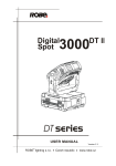
incorporated herein by reference is a copy of a User Manual
for Robe Lighting SRO’s Digital Spot 7000 DT series lumi
The improved system then blends together the pre
other embodiments may be devised Which do not depart from
cut images of the original image being projected by projec
the scope of the disclosure as disclosed herein. The disclosure
tion luminaires so as to re-create the original image at each
has been described in detail, it should be understood that
Aug. 12, 2010
US 2010/0201702 A1
Various changes, substitutions and alterations can be made
2. A projection luminaire of claim 1 Where the controlled
hereto Without departing from the spirit and scope of the
image parameter is the independent control of brightness
disclosure.
and/or contrast.
What is claimed is:
1. A projection luminaire comprising:
a light engine for generating a geometrically regular
shaped beam of light With demarkable boarder areas;
image processor proving user control of the siZe of the
demarkable boarder areas;
image processor providing user to control parameters of
the demarked boarder areas independently of control of
such parameters of the image not part of the demarked
boarder areas.
3. A projection luminaire of claim 1 Where the controlled
image parameter is the independent control of intensity of
color components of the image such as red, and/or green,
and/or blue.
4. A projection luminaire of claim 1 Where the controlled
image parameter is the independent control of gamma cor
rection.
5. A projection luminaire of claim 4 Where the control
curve of the gamma correction is controllable by the user.
6. A projection luminaire of claim 5 Where the control
curve of the gamma correction is linear.
*
*
*
*
*








![[U2.07.02] Notice d`utilisation de la sous-structuration](http://vs1.manualzilla.com/store/data/006366088_1-a41bd16bb9ec95233d9e4a5fe376e179-150x150.png)


![[U2.07.02] Notice d`utilisation de la sous-structuration](http://vs1.manualzilla.com/store/data/006382462_1-38a069c02ce610d879e6c9ba6e171712-150x150.png)
