1
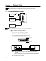
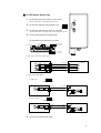
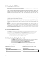
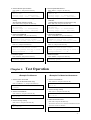
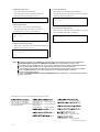
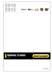
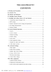
HP-13009-3
Universal Controller
SCX10
STARTUP MANUAL
Thank you for purchasing an Oriental Motor product.
The SCX10 has been designed to be easy to use, and contains several unique functions.
This startup manual should help you to get to know the product quickly. Please read the separately
supplied operating manual for more detailed information.
Chapter 1
Safety Precautions
The precautions described below are intended to prevent danger or injury to the user and other
personnel through safe, correct use of the product.
Use the product only after carefully reading and fully understanding these instructions.
Warning
Handling the product without observing the instructions that accompany a
"Warning" symbol may result in serious injury or death.
Caution
Handling the product without observing the instructions that accompany a
"Caution" symbol may result in injury or property damage.
Note
The items under this heading contain important handling instructions that the
user should observe to ensure safe use of the product.
Memo
This contains information relative to the description provided in the main text.
Warning
General
• Do not use the product in explosive or corrosive environments, in the presence of flammable gases,
locations subjected to splashing water, or near combustibles. Doing so may result in fire or injury.
• Assign qualified personnel the task of installing, wiring, operating/controlling, inspecting and
troubleshooting the product. Failure to do so may result in fire or injury.
• Do not transport, install the product, perform connections or inspections when the power is on.
Always turn the power off before carrying out these operations. Failure to do so may result in
electric shock.
• When the device’s protective function is triggered, first remove the cause and then clear the
protective function. Continuing the operation without determining the cause of the problem may
cause malfunction of the device, leading to injury or damage to equipment.
Installation
• Install the device in an enclosure in order to prevent injury.
Connection
• Keep the device’s input-power voltage within the specified range to avoid fire.
• For the device’s power supply use a DC power supply with reinforced insulation on its primary and
secondary sides. Failure to do so may result in electric shock.
• Connect the cables securely according to the wiring diagram in order to prevent fire.
Operation
• Turn off the device power in the event of a power failure, or the motor may suddenly start when the
power is restored and may cause injury or damage to equipment.
Repair, Disassembly and Modification
• Do not disassemble or modify the device. This may cause injury. Refer all such internal inspections
and repairs to the branch or sales office from which you purchased the product.
-2-
Caution
General
• Do not use the device beyond its specifications, or injury or damage to equipment may result.
Transportation
• Do not hold the device cable. This may cause damage or injury.
Installation
• Keep the area around the device free of combustible materials in order to prevent fire or skin
burn(s).
Operation
• To avoid injury, remain alert during operation so that the device can be stopped immediately in an
emergency.
• Before supplying power to the device, turn all start mean inputs to the device to "OFF." Otherwise,
the device may start suddenly and cause injury or damage to equipment.
• When an abnormality is noted, stop the operation immediately, or fire or injury may occur.
Disposal
• When disposing of the device, treat it as ordinary industrial waste.
Chapter 2
List of Items
• Universal controller (SCX10)
1 unit
• CD-ROM
1 pc.
(Immediate Motion Creator for CM/SCX Series (GUI Software),
Startup manual, Operating manual, CANopen EDS file,
USB driver, .NET Framework 2.0)
• Connector set
1 set (packed in a bag)
RS-232C connector (3 pins): 1
CANopen connector (4 pins): 1
Power connector (3 pins): 1
• Encoder connector housing/contact (8 pins)
1 set ( packed in a bag)
• Startup manual (This manual)
1 copy
-3-
Preparation
Chapter 3
Note
Before operating the motor, check the condition of the surrounding area to ensure safety.
3.1 Connection and Switch Setting
USB
PC
24 VDC
Power supply
+
-
D-SUB 25pin connector
Driver
Note
A USB Mini cable and a D-SUB connectors are not supplied with the SCX10.
For all drivers except AR series
1.
2.
Set the driver pulse Input mode to 1 pulse mode.
See the driver manual for information on how to set.
Connect Pulse/Direction signals to the driver connector
Pin assignment for D-SUB 25 pin connector
2: DIR+/CCW+
1: PLS+/CW+
14: PLS-/CW15: DIR-/CCW-
*See the driver manual for pulse input circuit and pin assignment on the driver.
The following example shows photo-coupler pulse input type drivers. (1-pulse mode)
Driver
Memo
3.
-4-
PLS+
PLS+/CW+
PLS-
PLS-/CW-
DIR+
DIR+/CCW+
DIR-
DIR-/CCW-
SCX10
1
14
2
15
The 5 V/24 V and SOURCE/SINK switch settings are not required for test
operation.
After the test operation, set those switches according to the Operating Manual.
Connect the 24 VDC power supply
2.
Set the driver pulse input mode to 1 pulse mode.
See the AR driver user manual about how to set.
Set the driver interface voltage switch to 5 V
5V
3.
4.
DRIVER
1.
24V
Set the driver interface logic switch as you desire
*Connections differ according to the switch settings as below.
5V 24V SOURCE SINK
For AR series driver only
Connect Pulse/Direction and CON signals
Pin assignment for D-SUB 25 pin connector
6: GND
13: 5V /24V OUT
2: DIR+/CCW+
1: PLS+/CW+
7: CON
14: PLS-/CW15: DIR-/CCW-
• Pulse (PLS) / Direction (DIR) signals
AR Driver
31
32
35
36
PLS+
PLS+/CW+
PLS-
PLS-/CW-
DIR+
DIR+/CCW+
DIR-
DIR-/CCW-
SCX10
1
14
2
15
• Current ON (CON) signal
a. Sink Logic
SOURCE
AR Driver
22
23
SINK
IN-COM
C-ON
5V
5V / 24V OUT
SCX10
13
CON
7
GND
b. Source Logic
SOURCE
AR Driver
22
23
SINK
IN-COM
GND
C-ON
CON
SCX10
6
GND
7
5V
5.
Connect the 24 VDC Power supply.
-5-
3.2 Installing the USB Driver
Insert the supplied CD into the CD drive of the computer, power on the SCX10 and Connect to a USB port using a
Mini-B cable. You will then be asked to install the USB driver.
Windows 2000: The “Found New Hardware Wizard” will be launched when the SCX10 is connected. Click
“Next”. For the FT232 USB UART installation, select “Search for a suitable driver for my device”, and click “Next”.
Check the box next to “Specify a location” and uncheck all others. Click “Next”. Click “Browse”. Select the
applicable CD drive and click “Open”. Locate the “USB_Driver” folder and click “Open”. Click “OK”. Click
“Next”. After successful installation, click “Finish”. The installation of the USB Serial Port is then asked by
Windows. Repeat same procedure as the above FT232 USB UART installation. After successful installation, click
“Finish”.
Windows XP: The installation of the FT232R USB UART is asked for by Windows when the SCX10 is connected.
Select “Install the software automatically”, and click “Next”. After successful installation, click “Finish”. The
installation of the USB Serial Port is then asked for by Windows. Select “Install the software automatically”, and
click “Next”. After successful installation, click “Finish”.
Windows Vista: The installation of the FT232R USB UART is asked by Windows when the SCX10 is connected.
Select “Locate and install driver software”, and click “Next”. After successful installation, click “Close”. The
installation of the USB Serial Port is then asked for by Windows. Click “Next”. After successful installation, Click
“Close”.
Windows 7: Open the Device Manager. Right click on “FT232R USB UART” and select “Update Driver
Software”. Select “Browse my computer for driver software”. Click “Browse” and select the applicable CD drive,
check the box next to “Include subfolders” and Click “Next”. After successful installation, click “Close”. Go back to
the Device Manager, right click on “USB Serial Port” and select “Update Driver Software”. Repeat same procedure
as the above FT232R USB UART installation.
3.3 Terminal Software Setup
The SCX10 can be controlled by any terminal software. The HyperTerminal application supplied with Windows
2000 and Windows XP, the Immediate Motion Creator for CM/SCX Series (GUI Software, included in
CD-ROM. See next page for installation instructions) and other general terminal software can be used.
Communication Setting: 8 bits, 1 stop bit, no parity, Baud rate: 9600 bps
*The default USB/RS-232C baud rate of the SCX10 is 9600 bps.
3.4 Initial Setting (Setting the User Unit)
In the SCX10, actual motion distance of user application, such as "mm", "inch" and "revolution" is
used, instead of pulse unit that is commonly used in controllers and pulse generators.
Set the following parameters and save them to the SCX10 EEPROM.
The parameter MR for the SCX10 is set to match the motor/motorized actuator resolution.
<Example For Motors>
<Example For Motorized Actuators>
Example (Motor resolution: 1000)
Example (Motorized actuator resolution: 0.01mm)
1. Set the user unit
Enter "UU=Rev", and press the Enter key.
1. Set the user unit
Enter "UU=mm", and press the Enter key.
>UU=Rev
UU=Rev
-6-
>UU=mm
UU=mm
2. Set the distance per revolution
Enter "DPR=1", and press the Enter key.
>DPR=1
DPR=1(1) Rev
Position range = +/- 500000(500000)
Velocity range = 0.001 - 12400(12400)
3. Set the motor resolution according to the driver
setting.
See the driver operating manual.
Enter "MR=1000", and press the Enter key.
>MR=1000
MR=1000(1000)
Position range = +/- 500000(500000)
Velocity range = 0.001 - 1240(1240)
4. Save to the EEPROM
Enter "SAVEPRM", and press the Enter key.
>SAVEPRM
(EEPROM has been written 5 times)
Enter Y to proceed, other key to cancel.
Enter "Y", and press the Enter key.
>SAVEPRM
(EEPROM has been written 5 times)
Enter Y to proceed, other key to cancel. Y
Saving Parameters........OK.
5.Reset the system
Enter "RESET", and press the Enter key.
>DPR=1
DPR=1(1) mm
Position range = +/- 500000(500000)
Velocity range = 0.001 - 12400(12400)
3. Set the parameter MR according to the actuator
resolution.
(1mm/actuator resolution=1mm/0.01mm=100)
Enter "MR=100", and press the Enter key.
>MR=100
MR=1000(100)
Position range = +/- 500000(500000)
Velocity range = 0.001 - 1240(12400)
4. Save to the EEPROM
Enter "SAVEPRM", and press the Enter key.
>SAVEPRM
(EEPROM has been written 5 times)
Enter Y to proceed, other key to cancel.
Enter "Y", and press the Enter key.
>SAVEPRM
(EEPROM has been written 5 times)
Enter Y to proceed, other key to cancel. Y
Saving Parameters........OK.
5.Reset the system
Enter "RESET", and press the Enter key.
>RESET
Resetting system.
>RESET
Resetting system.
Chapter 4
2. Set the parameter DPR to 1
Enter "DPR=1", and press the Enter key.
Test Operation
<Example For Motors>
1. Set the motor current ON
(For the AR series driver only)
Enter "CURRENT=1", and press the Enter key.
>CURRENT=1
CURRENT=1
<Example For Motorized Actuators>
1. Set the move distance
Enter "DIS=10", and press the Enter key.
>DIS=10
DIS=10 mm
2. Set the running velocity
2. Set the move distance
Enter "DIS=10", and press the Enter key.
>DIS=10
DIS=10 Rev
Enter "VR=1", and press the Enter key.
>VR=1
VR=1 mm/sec
3. Make the actuator move
3. Set the running velocity
Enter "VR=1", and press the Enter key.
>VR=1
VR=1 Rev/sec
Enter "MI", and press the Enter key.
The actuator starts to move in the forward direction, and
will move 10 mm at 1 mm/sec.
>MI
>
-7-
4. Make the motor move
4. Invert the direction
Enter "MI", and press the Enter key.
Enter "DIS= -10" and "MI", both followed by
The motor starts to move in clockwise direction,
pressing the Enter key. The actuator will move 10 mm at
and will rotate 10 revolutions at 1 rev/sec.
1 mm/sec in the reverse direction.
>MI
>
>DIS=-10
DIS=-10 mm
>MI
>
5. Invert the direction
Enter "DIS= -10" and "MI", both followed by
5. Change the running velocity
pressing the Enter key. The motor will rotate 10
Enter "VR=10" and "MI", both followed by the Enter
revolutions at 1 rev/sec in reverse direction.
key. The actuator will move at 10mm/sec.
>DIS=-10
DIS=-10 Rev
>MI
>
>VR=10
VR=10 mm/sec
>MI
>
6.Change the running velocity
Enter "VR=2" and "MI", both followed by the Enter key.
The motor will rotate at 2 rev/sec.
>VR=2
VR=2 Rev/sec
>MI
>
Memo
While all commands to the SCX10 can be made using general terminal software, the supplied GUI,
Immediate Motion Creator for CM/SCX Series (IMC), is recommended for its ease of use.
To install, insert the supplied CD into your CD drive. Open the Explorer, select the applicable CD drive,
open the IMC folder, double click on "setup.exe" and follow the on screen instructions.
*For Windows 2000 and Windows XP users, the .NET Framework 2.0 software needs to be installed
prior to the IMC installation. The .NET Framework 2.0 is on the supplied CD, under the
DotNet_Framework2_0 folder.
*See "7.7 Immediate Motion Creator for CM/SCX Series (GUI Software)" in the Operating Manual for
further information.
• Please contact your nearest Oriental Motor office for further information.
Technical Support Tel:(800)468-3982
8:30 A.M. to 5:00 P.M., P.S.T. (M-F)
7:30 A.M. to 5:00 P.M., C.S.T. (M-F)
E-mail: [email protected]
www.orientalmotor.com
Headquarters and Düsseldorf Office
Tel:0211-52067-00
Fax:0211-52067-099
Munich Office
Tel:089-3181225-00 Fax:089-3181225-25
Hamburg Office
Tel:040-76910443
Fax:040-76910445
Tel:(02)8228-0707
Fax:(02)8228-0708
Tel:(6745)7344
Fax:(6745)9405
Tel:(03)22875778
Fax:(03)22875528
Tel:01256-347090
Fax:01256-347099
Tel:66-2-254-6113
Fax:66-2-254-6114
Tel:01 47 86 97 50
Fax:01 47 82 45 16
KOREA
Tel:(032)822-2042~3
Fax:(032)819-8745
Tel:02-93906346
Fax:02-93906348
Headquarters Tokyo, Japan
Tel:(03)3835-0684
Fax:(03)3835-1890
Printed on Recycled Paper
-8-