1
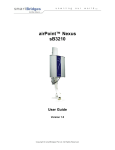
GRAND FIRE BUILT-IN SIDE BURNER ACCESSORY CARE & USE / INSTALLATION 08/13 1 2 A MESSAGE TO OUR CUSTOMERS Thank you for selecting a GRANDFIRE Professional Grill. Your grill has been designed and built with every attention to detail and offers unique and powerful features. We have developed this Users’ Manual to assist you on the use and maintenance requirements. It contains valuable information on how to properly install, operate and maintain your new appliance for safety and best performance. Thanks again for your choice. Enjoy! 3 TABLE OF CONTENTS SAFETY AND INSTRUCTIONS----------------------------------------------------------------------------------------------------------------5 BUILT-IN INSTALLATION ---------------------------------------------------------------------------------------------------------------------7 CONNECTIONS ---------------------------------------------------------------------------------------------------------------------------------9 CHECKLIST BEFORE EACH USE ------------------------------------------------------------------------------------------------------------11 LIGHTING THE SIDE BURNER--------------------------------------------------------------------------------------------------------------11 CLEANING AND MAINTENANCE----------------------------------------------------------------------------------------------------------13 WARRANTY SERVICE ------------------------------------------------------------------------------------------------------------------------14 LIMITED WARRANTY INFORMATION----------------------------------------------------------------------------------------------------14 EXPLODED PARTS VIEWS & PARTS LISTS-----------------------------------------------------------------------------------------------16 NOTE TO INSTALLER This manual must remain with the grill. An installer-supplied gas shut-off valve must be installed in an easily accessible location. Outdoor installations must conform to local codes or, in the absence of local codes, with AUST/NZ: Australian Standards Code AS: 4557 as well as the requirements of any local council, gas, electricity authority or other statutory regulation. Spanner tightens all gas fittings as per instructions. 4 SAFETY PRACTICES & PRECAUTIONS WARNING OUTDOOR USE ONLY DO NOT OPERATE THIS APPLIANCE BEFORE READING THE INSTRUCTION BOOKLET DO NOT PLACE ARTICLES ON OR AGAINST THIS APPLIANCE DO NOT STORE CHEMICALS OR FLAMMABLE MATERIALS, OR SPRAY AEROSOLES NEAR THIS APPLIANCE DO NOT OPERATE THE APPLIANCE INDOORS DO NOT OPERATE IN AN ENCLOSED AREA DO NOT OPERATE THIS APPLIANCE BEFORE LEAK CHECKING HOSES AND GAS CYLINDER CONNECTION DANGER!!! What to Do If You Smell Gas Shut off gas to the appliance. Extinguish any open flame. Open lid. If odor continues, keep away from the appliance and immediately call your gas supplier or your fire department. DO NOT STORE SPARE GAS CYLINDER IN THIS COMPARTMENT OR NEAR THIS APPLIANCE; USE ONLY THE CYLINDER STORAGE FACILITY PROVIDED. IF THIS WARNING IS NOT FOLLOWED, A FIRE CAUSING INJURY OR DAMAGE MAY OCCUR. For Your Safety Do not store or use gasoline or other flammable vapours or liquids in the vicinity of this or any other appliance. An LPG cylinder not connected for use shall not be stored in the vicinity of this or any other appliance. Below is a summary of important safety warnings. It is not a complete list. Read this Entire instruction booklet before installation or operation of your barbecue. INSTALLATION SAFETY Warning: Contact your local municipality for any building codes regulating the installation of outdoor barbecue appliances. Outdoor installations must conform to local codes or, in the absence of local codes, with the following: AUST/NZ: Australian Standards Code AS: 5601, as well as the requirements of any local council, gas, electricity authority or other statutory regulation. Spanner tightens all gas fittings as per instructions. SAFE LOCATION Do not use barbecue indoors. This is an outdoor cooking appliance. It must only be used outdoors, and must not be used in a building, garage or any other enclosed area. Do not store combustible materials, gasoline or flammable liquids or vapors within 45 cm of barbecue. This barbecue is not designed for marine use, and shall not be installed on a boat or any marine craft. Keep the barbecue and cylinder well ventilated. Do not obstruct the flow of air around the barbecue, as this is required for proper combustion. For built-in situations, allow adequate ventilation for the barbecue and cylinder, and adequate protection from adverse weather. Allow clear access to the entire gas supply hose and regulator. Use your barbecue only on a level surface. 5 GAS CYLINDER SAFETY Do not install the gas cylinder beneath the barbecue unless in conjunction with an approved trolley. Keep the cylinder protected from heat. Only one gas cylinder may be attached to the appliance at any one time. When using an LPG supply system (e.g. portable LPG cylinder) in an enclosure, ventilation must be provided. Keep ventilation opening of any cylinder enclosure clear and free of any debris. Gas vapor is highly explosive and can cause serious bodily injury or damage to property if allowed to accumulate in a confined space and ignited. Have the gas cylinder filled by an authorized LPG supplier. Close the gas cylinder valve after each use. Do not smoke or use a naked flame near the gas cylinder while disconnecting the gas line between the appliance and gas cylinder. Do not use a rusty or dented gas cylinder or cylinder with a damaged gas valve. Do not fill the gas cylinder beyond 80% capacity. Do not store gas cylinder indoors, or in any enclosed area. Do not lay the gas cylinder down. SAFE OPERATION This barbecue becomes very hot during use, so: Keep young children away. When handling hot components, the use of protective gloves is recommended. Do not allow the flexible gas supply hose or any electrical cord to come in contact with any heated surface of the appliance. DO NOT wear loose garments or sleeves when using the barbecue. Do not leave your barbecue unattended whilst in use. Do not use plastic or glass utensils on the barbecue. Do not operate barbecue in strong winds. Do not move the appliance during use. Do not allow children to operate this appliance. Do not operate window roasting hoods in the rain. Do not disconnect any gas fittings while the appliance is operating. SAFE LIGHTING Always leak-test with a solution of soapy water. Do not test for gas leaks with a naked flame. Always fully open the roasting hood or remove the metal lid of the appliance before lighting. Visually check burner flames to confirm lighting. Do not lean over barbecue when lighting. Do not use charcoal or any other solid fuel in this appliance. SAFE CARE AND MAINTENANCE Always keep your barbecue clean: When you have finished cooking turn the grill burners to high for up to 10minutes to burn off any excess grease. Make sure your grease pan is clean to avoid a grease fire. Let the barbecue cool before replacing any lid or cover. 6 Empty and clean grease tray. Clean the barbecue at least twice annually. Check main opening, throat and vent to each burner and pilot flame tube regularly for insect nests (e.g. wasp, ants or spiders). Nests are dangerous and must be cleaned out thoroughly. Do not use caustic based cleaning agents on the barbecue. Check all gas hoses and line connections for damage, cuts or cracks each time the appliance is to be used. Do not attempt to modify the appliance. Any modification to this appliance may be dangerous and may void the warranty. Do not attempt to dismantle or adjust control valves or regulator. IF THERE IS A FIRE Most fires are caused by a buildup of grease, or by an improper gas connection. Ensure all people and pets are kept as far away as possible. If possible, turn the gas off at the cylinder or for piped installations, on the on/off valve. Use a fire extinguisher if possible. If water is the only fire retardant available, thoroughly soak the area around the appliance. When spraying water on the barbecue itself, do not use a strong jet of water, as this may cause splashing of burning grease, resulting in a further spreading of the fire. Rather spray lightly over the frame cooking surfaces to cool the appliance below ignition temperature. IMPORTANT! GRILLING IN WINDY CONDITIONS Using your grill in windy conditions may disrupt the front-to-back air flow. While grilling with all burners on high and the hood closed, you notice that the temperature gauge fails to rise…be careful. High wind may keep hot gases from exiting the rear of the grill, the control panel and knobs may have become extremely hot. On breezy days, be careful not to leave the front hood down for more than 15 minutes when the burners are on high. (Never leave the grill unattended when in operation) If you suspect the grill is overheating, using an oven mitt to open the front hood. Then adjust the burner control knob to a lower setting. Reposition the grill so prevailing winds are not blowing into the rear of the grill. Note: Any damage caused from use in windy conditions, such as melted knobs or igniter wire, or control panel discoloration from heat buildup, is excluded from warranty coverage. BUILT-IN INSTALLATION BEFORE YOU START If your dealer has had your appliance delivered, please check for visible damage to the outer carton immediately. Please make the delivery person aware of the damage right away and please call your dealer. If the damage is not noticed until the merchandise is unpacked you should notify your dealer within 7 days of the delivery date. Please remove all packing materials for securing the parts inside the unit, such as plastic zip-tie and friendly foam. IMPORTANT NOTES: This is an outdoor appliance. Ensure your appliance is positioned safely away from anything that can catch fire. Indoor Use: Under no circumstances this appliance can be used indoors. This includes garages or any other enclosed areas. Clearance from Combustibles: Ensure your appliance remains at a distance of at least 45 cm (18”) from any 7 combustible material such as wood, gyp rock, paper and plants. Do not store combustible materials, gasoline or flammable liquids or vapors within 45 cm (18”) of the appliance. Adequate Ventilation: Ensure there is adequate ventilation for both the appliance and cylinder. This is required not only for proper combustion, but also to prevent gas buildup. Please leave at least 1200mm height clearance for cooking top to any ceiling above. Firm Level Surface: Use your appliance only on a firm level surface. This barbecue is not designed for recreational vehicles, and shall not be installed on a boat or any marine craft. Protection from Weather: Keep the appliance protected from adverse weather, including rain and high winds. Polyvinyl covers are available that have been specially designed for this range of appliances. INSTALLATION INTO THE BUILT-IN ISLAND Warning: THE APPLIANCE IS TO BE INSTALLED ONLY ON A NON-COMBUSTIBLE SURFACE. Warning: THERE MUST BE AT LEAST A 15MM GAP (>15MM CLEARANCE) UNDER THE APPLIANCE The accessory drops into the opening shown in the cutout detail drawing and hangs from its counter-top trim. See below drawings for the cutout dimension: Figure 01 GFKSB1 Figure 02 GFKSB2 8 CONNECTIONS WARNING NEVER CONNECT A GAS LINE DIRECTLY TO THE ACCESSORY. A PRESSURE REGULATOR MUST BE INSTALLED ON GAS EQUIPMENT. ALL LOCAL CODES REQUIRE IT AND GRANDFIRE SUPPLIES THE CORRECT REGULATOR WITH YOUR ACCESSORY. REMOVING OR FAILING TO INSTALL THE PRESSURE REGULATOR CAN RESULT IN FIRE AND SERIOUS PERSONAL INJURY AND WILL VOID THE WARRANTY. CONNECTION WITH GAS GRILL A T-type connector should be used to connect side burner accessory with your gas grill and gas cylinder. This connector is always offered by manufacturer Figure 04 T-connector 5/8”UNC Figure 03 Connect GFKSB with Gas grill W/ Gas Cylinder Connection with Gas Cylinder (LP & NG) LP GAS: Connect the hose and regulator to the gas inlet at the right hand side of the back grill. The gas inlet of the barbecue is 5/8 UNC male flare fitting (Figure 04). Do not subject the hose to twisting. Secure all joints spanner (wrench) tight but do not over-tighten. Check for leaks per leaking test procedure. Grills set up for LP gas come equipped with an LP hose/regulator assembly for connection to a standard 9kg cylinder. The most flexible arrangement is a portable LPG/propane gas cylinder attached by a special hose and regulator to your barbecue. Although the cylinder needs to be refilled or exchanged when empty, this installation has the advantage of being more mobile, and not requiring the services of a licensed gas fitter. Figure 05 CAUTION! Before connecting LP cylinder to regulator, check that all grill burners and rotisserie valves are in the OFF position and open grill lid. 9 WARNING DO not change the regulator/hose assembly or use any other assembly than the one supplied with your grill. DO not store a spare LP-gas cylinder under or near this appliance. Never fill the cylinder beyond 80 percent full. If the information above is not followed exactly, a fire causing death or serious injury may occur. Natural Gas Natural gas installation should be carried out by a qualified technician/plumber. Fit the natural gas regulator supplied directly to the barbecue inlet located on the right side of the appliance using a minimum inner diameter of 13mm, no more than 1200mm length, Class A, flexible hose connected to a bayonet point. Refer to local installation code for pipe sizing details. Secure all joints spanner tight but not over- tighten them. Test gas pressure by removing the last burner from the left hand side of the barbecue and attaching a hose and pressure gauge to the end of the gas valve. Turn on 2 burners on high and check the pressure. Inlet pressure should be 4.0” WC or 1.00 KPa. For built-in island installations that use flexible hosing to connect to natural gas, a chain or similar restraining device must be fitted to prevent strain on the gas supply line. One end of the chain should attach to the barbecue; the other end should attach to a fixed structural point close to where the hose connects to the gas piping. The chain must be at least 30% shorter than the gas supply line. In this way, if the barbecue is accidentally moved, the chain stops the barbecue from stretching the hose. The appliances must be isolated from the gas supply piping system by closing its manual shutoff valve during any pressure testing of the gas supply piping system. Figure 06 Connections W/ LP&NG Gas 10 CHECKLIST BEFORE EACH USE Do you smell gas? If yes, shut off everything and call the gas company or a qualified plumber to check for leaks. Will you stay with the side burner during the entire cooking process? If not, gather what you need before starting the lighting process. Is your cooking area free and clear of any combustibles, besides your food, which might ignite? If no, clear the area before starting the lighting process. Do all control knobs turn freely? If not, call for service. If you are using a portable propane cylinder, is it connected and leak tested? If not, check the connection before continuing. Do you know where your side burner’s main gas supply shut-off valve is located? If not, locate it before continuing. Are all burners properly seated in the side burner? If not, seat the burners properly before continuing. Is the wind blowing just lightly and not blowing on the side burner? If not, wait until the wind subsides or turn your free-standing grill so the wind goes into the front of the grill. LIGHTING THE SIDE BURNER Before proceeding, you need to establish the gas type which your barbecue will run on, and the style of installation you need. Natural Gas or Propane: Before beginning installation or assembly, check the gas type which the barbecue is designed for. In most countries the choices are natural gas or propane. You will find the gas type label on the side of your barbecue. If your barbecue uses the incorrect gas type, or if you are unsure, consult your dealer before going any further. Using the wrong type of gas for a barbecue is extremely dangerous. Natural Gas Conversion: If a newly purchased barbecue is made for propane. A natural gas conversion kit may be available to allow your barbecue to run on natural gas. NATURAL PROPANE GAS GAS Important: Do not try to convert your barbecue by yourself! It may cause serious injury or death with improper operations! Please contact your local dealer or authorized gas fitter. Figure 07: Rating Plate Sample Ensure that the gas supplied meets with the minimum pressure requirements. Do not operate the grill on any gas other than that for which the grill has been set. 11 Fuel Max Inlet Min Under Full Load Injector Size Natural Gas 1.75 kPa 1.00 kPa 2.06mm Propane 3.5 kPa 2.75 kPa 1.20mm Both the regulator and the burner injectors have been set for the type of gas specified on the rating plate. LEAK TESTING DANGER! To prevent fire or explosion hazard, DO NOT smoke or allow any potential source of ignition(sparks, electrical arcing, etc) in the area while performing a leak test. Leak test should be conducted outdoors only. Never conduct a leak test using fire or flame. Perform a leak test at least once each year whether the gas supply cylinder has been disconnected or not. In addition, anytime the gas cylinder is connected to the regulator or any part of the gas system is disconnected or replaced, conduct leak test. Use only a leak testing solution as specified below. DETAILED PROCEDURE: 1. Prepare a leak testing solution of sudsy water by mixing in spray bottle half-liquid soap and half water. 2. Check and make sure all the control knobs are in the OFF position. 3. Turn cylinder valve knob counter clockwise one turn to open. 4. Apply leak-testing solution by spraying on joints of the gas delivery system. 5. Blowing bubbles in the soap solution indicates that a leak is present. 6. Stop a leak by tightening the loose joint or by replacing the faulty part with a replacement part recommended by the manufacturer. Do not attempt to repair the cylinder valve if it should become damaged. The cylinder must be replaced. 7. If you are unable to stop a leak, shut off the gas supply at the cylinder valve. Remove the cylinder from the grill. Call an authorized gas appliance service technician or LP gas dealer. Do not use the appliance until the leak is corrected. 8. Push in and turn any control knob to release pressure in the hose and manifold. 9. Turn off the control knob. BUBBLES=LEAK LEAK TEST POINTS To grill To propane tank To side burner Figure 09 Test Points on Joints Figure 10 Gas Cylinder Connection BEFORE YOU LIGHT THE SIDE BURNER Perform the following checks Make sure all gas connections are tight and leak tested. You do not smell gas before you light the appliance. If you do smell gas, shut everything off and get a qualified plumber to check for leaks. Ensure the cooking surfaces are clean and hygienic Check the control knobs are on the off position. Do not attempt to light the burners if the smell of gas is present. Check that the gas supply is turned on Ensure the lid of the side burner is removed. If not, gases can build up inside the hood and create a dangerous 12 situation. Make sure the drip tray in place. Do not leave the appliance unattended while cooking. WARNING! NEVER attempt to light a burner if you smell gas. Always keep the lid open (side-burner lids must be completely removed) when lighting your grill. Releasing fuel into a closed grill before lighting will increase the risk of explosion, property damage, personal injury or death. Keep your face and body as far from the grill as possible when lighting. Any time a burner doesn’t light within 5 seconds, turn off the control, wait 5 minutes for gas to dissipate, and repeat the lighting procedure. LIGHT YOUR SIDE BURNER Remove the Lid. Keep your face as far away from the burners as possible. Slowly rotate the burner knob counter-clockwise to the high position. You will hear a loud click as the electronic lighter produces a spark. Listen for the sound of the gas igniting. If the burner does not light on the first try, repeat immediately. If the burner does not light in 5 seconds then wait five minutes until the gas clears before attempting to light it again. Repeat the procedure or try the manual lighting procedure below. Upon successful lighting, repeat the process on the other burners you wish to light. To shut off the burners, rotate the knob and turn to OFF. It is normal to hear a popping sound when the burners are turned off. COLD WEATHER WARNING: PROPANE Extremely cold temperatures may cause your burner to light inside the burner instead of outside. Once lit, if you hear a “whooshing” sound, immediately turn the burner knob off to extinguish the flame and then immediately re-light the burner. LOW HEAT BURNER ADJUSTMENT To adjust the burner low setting: Make sure the appliance is cool. Remove racks so that you can see the flames clearly while adjusting the burners. Light the burner and set it to “LOW” Pull off the control knob. Hold the valve shaft with pliers, insert a small screwdriver into the shaft, watch the flame and adjust it to a minimum stable setting. Figure 11 CLEANING & MAINTENANCE Your new accessories must be kept clean and properly maintained to maximize its performance and longevity as the same as your gas grills. Clean the internal parts of the accessories regularly as determined by the amount of use and food cooked. The entire accessories should be cleaned at least twice a year. TO ENSURE SAFE AND PROPER USE, FOLLOW THESE DIRECTIONS CAREFULLY: CLEANING THE COOKING GRATES The easiest way to clean the cooking grates is to scrub them immediately after cooking with the burners off. Wear a 13 grill mitt to protect your hand from the heat and steam. We recommend using a brass bristled grill brush that is dipped in water. Dip the brush frequently to increase the amount of steam, which makes the cleaning process easier by softening any food particles. CLEANING THE DRIP TRAY The drip tray will collect grease from the main grill area. The tray should be cleaned after every use to avoid the possibility of a grease fire. Be sure to allow the drip tray to cool prior to cleaning. You may clean it with a solution of warm soapy water. Rinse thoroughly to avoid staining. IMPORTANT All of the gas control knobs must be turned to the “OFF” position, and the fuel must be off. 1. Remove burners from grill by carefully lifting each burner up. 2. Wire brushing the outer surface of the burner to remove food residue and dirt. Clean any clogged ports with a stiff wire or an opened paper clip. 3. Inspect the burner for damage (cracks or holes). If any damage is found, replace burner before use. 4. Upon reinstallation, inspect gas valve orifices for cleanliness and the condition and location of igniters. CARE OF STAINLESS STEEL Do NOT use wire wool pads, scrappers, harsh abrasive, scoring materials, bleaches, or harsh cleaners on your cart or grill, or allow salt and vinegar mixtures to remain in contact for a long period of time. This will cause scratching, scoring, rusting and pitting. We recommend that you clean stainless steel components with a cleaner that is approved for stainless steel and only clean when the grill is cool and in indirect light. Never use steel wool. HOOD AND BODY Wipe the inside hood and body with detergent and hot water. The external surfaces may be cleaned in the same fashion. Wipe all areas dry before storing. STORAGE Please ensure that all units of the grill are clean before storing. WARRANTY SERVICE HOW TO OBTAIN SERVICE: For warranty service, please contact your local dealer. Before you call, please have the following information available: • Model Number (see rating plate) • Serial Number (see rating plate) • Proof of purchase by the original owner • Date of installation • Brief description of problem Your satisfaction is importance to us. If a problem cannot be resolved to your satisfaction, please feel free to contact us anytime. Hauland PTY Limited. Website: www. Grandfirebbqs.com.au Email: [email protected] NZ office Hauland Limited. Unit b, 1 Douglas Alexander Parade, Albany Auckland Hotline: 0800 BUFFALO 14 Website: www.hauland.co.nz Email: [email protected] LIMITED WARRANTY INFORMATION LIMITED TEN YEAR WARRANTY The stainless steel body housing and cabinets are warranted to be free from defects in material and workmanship when subjected to normal domestic use and service for ten years from the original purchaser. This warranty is limited to the replacement of defective parts, with the owner paying all other costs including labor. LIMITED FIVE YEAR WARRANTY The burners, cooking grates and plates are warranted to be free from defects in material and workmanship when subjected to normal domestic use and service for a period of five years from the date of purchase. This warranty is limited to the replacement of defective parts, with the owner paying all other costs including labor. LIMITED TWO YEAR WARRANTY The gas valves and ignitions are warranted to be free from defects in material and workmanship when subjected to normal domestic use and service for a period of two years from the date of purchase. This warranty is limited to the replacement of defective parts, with the owner paying all other costs including labor. LIMITED ONE YEAR WARRANTY All other components are warranted to be free from defects in material and workmanship when subjected to normal domestic use and service for a period of one year from the date of purchase. LIMITATIONS AND EXCLUSIONS 1) Warranty applies to the original purchases and may not be transferred. 2) Warranty is in lieu of all other warranty, expressed or implied and all other obligations or liabilities related to the sale of use or use of its grill products. 3) Warranty shall not apply to damage resulting from misuse, abuse, alteration of or tampering with the appliance, accidental, hostile environment, flare-up fires, improper installation, or installation not in accordance with the instructions contained in this manual or local code. 4) Company shall not be liable for incidental, consequential, special or contingent damages resulting from its breach of this written warranty or any implied warranty. 5) No one has the authority to add to or vary this warranty, or to create any other obligation or liability in connection with the sales or use of the company’s products. Warranty shall not apply to cosmetic imperfections not affecting the structural integrity of the appliance, having been caused by fair wear and tear, or as a result of extreme seasonal or marine conditions. Warranty shall not apply to damage caused by acts of God, neglect of the product, or failure to maintain the product in full accordance with the User’s Manual. The term of this Warranty shall commence on the date of purchase, and is not subject to extension of any kind as a result of any repair or replacement being undertaken during the lifetime of the warranty. 15 EXPLODED PARTS VIEWS & PART LISTS GFKSB1 PARTS LIST ITEM PART NO. 1 GF26CP08 2 3 DESCRIPTION QTY ITEM PART NO. DESCRIPTION QTY Handle 1 11 SB1P11 Basin Assembly 1 SB1P02 Hood 1 12 GF32P28 Knob 1 SB1P03A Orifice LP (1.20mm) 1 13 SB1P13 Hood Bracket 2 SB1P03B Orifice NG (2.06mm) 1 14 SB1P14 Fire Ring Pedestal 1 4 SB1P04 Burner Pedestal 1 15 SB1P15 Fire Ring 1 5 SB1P05 Igniter Pin 1 16 SB1P16 Top Grate 1 6 SB1P06 90° Connector 1 17 Screw (M4x8) 2 7 SB1P07 Flex Tube(200mm) 1 18 Screw (M4x10) 4 8 SB1P08 Gas Hose Assembly 1 19 Nut (M4) 6 9 SB1P09 Valve 1 20 Screw (M4x6) 2 10 SB1P10 Igniter Wire(240mm) 1 21 Screw (M4x16) 4 16 GFKSB2 PARTS LIST ITEM 1 2 3 4 5 6 7 8 9 10 11A 11B 12 13 14A PART NO. GF26CP08 SB2P02 SB2P03 SB1P15 SB1P14 SB2P06 SB1P05 SB1P03A SB1P03B SB1P04 SB1P06 SB1P07 SB2P11 SB1P08 SB2P13 SB1P10 DESCRIPTION Handle Hood Grate Fire Ring Fire Ring Pedestal Body Assembly Igniter Pin Orifice LP (1.20mm) Orifice NG (2.06mm) Burner Pedestal 90° Connector Flex Tube(200mm) Flex Tube(420mm) Gas Hose Assembly Grease Tray Igniter Wire(240mm) QTY 1 1 2 2 2 2 2 2 2 1 2 1 1 1 1 1 ITEM 14B 15 16 17 18 19 20 21 22 23 24 25 26 27 28 PART NO. SB2P14 SB2P15 SB2P16 SB2P17 GF32P28 SB2P19 SB2P20 GFD42P27 DESCRIPTION Igniter Wire(480mm) Valve Latch Manifold Assembly Valve Knob Control Pane Front Frame Spacer Screw (M4x8) Screw (M4x16) Screw (M6x13) Screw (M5x25) Screw (M4x6) Screw (M5x13) Screw (M6x16) QTY 1 2 2 2 2 2 1 2 2 8 1 2 4 4 2 17 18 19 20