1
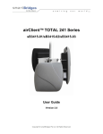
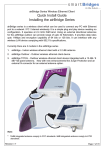
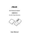
u n w i r i n g
o u r
airPoint™ Nexus
sB3210
User Guide
Version 1.0
Copyright © smartBridges Pte Ltd. All Rights Reserved.
w o r l d
TM
i n t e l l i g e n t
w i r e l e s s
p l a t f o r m
TABLE OF CONTENTS
ABOUT THIS DOCUMENT .................................................................................................... 3
OVERVIEW OF USER GUIDE ............................................................................................... 3
RELATED PUBLICATIONS ................................................................................................... 3
TECHNICAL SUPPORT CENTER ......................................................................................... 4
1.
1.1.
1.2.
1.3.
2.
INTRODUCTION......................................................................................................... 5
AIRPOINT™ NEXUS CONFIGURATION FEATURES ........................................................ 5
SYSTEM REQUIREMENTS ........................................................................................... 5
CHECKLISTS ............................................................................................................. 6
AIRPOINT CONFIGURATION.................................................................................. 10
USER LOGIN AND LICENSE AGREEMENT ................................................................... 10
WEB GUI ADMINISTRATOR PASSWORD CHANGE ...................................................... 12
USING THE CONFIGURATION PAGES: ....................................................................... 13
AIRPOINT BRIDGE CONFIGURATION PARAMETERS .................................................... 18
2.4.1. Ethernet Configurations ............................................................................. 18
2.4.2. Wireless Configuration ............................................................................... 18
2.4.3. Radio Protocol ............................................................................................. 20
2.5. BRIDGE CONFIGURATION .............................................................................................. 22
2.1.
2.2.
2.3.
2.4.
3. SECURITY........................................................................................................................ 26
4. TRAFFIC STATISTICS..................................................................................................... 31
5. TOOLS.............................................................................................................................. 32
5.1.1. SYSTEM CONFIGURATION .......................................................................................... 32
5.1.2. SNMP Security............................................................................................... 33
5.1.3. Reset Options................................................................................................ 34
5.1.6. NTP Time Server Setup ................................................................................ 35
5.2. PROFILE MANAGER ....................................................................................................... 36
5.2.1 Save Profile..................................................................................................... 37
5.2.2 Load Operating Profile .................................................................................. 38
5.2.3 Profile calendar .............................................................................................. 38
5.3. LINK TEST .................................................................................................................... 39
5.4. LINK BUDGET PLANNING ............................................................................................... 40
6. FIRMWARE UPGRADE ................................................................................................... 42
APPENDIX A - CONFIGURATION OF THE RADIUS SERVER.......................................... 44
APPENDIX B - USEFUL TERMS AND DEFINITIONS ........................................................ 51
APPENDIX C - SNMP TRAP................................................................................................ 54
APPENDIX D – LICENSE .................................................................................................... 55
airPoint™ Nexus User Configuration Guide
Page 2 of 55
i n t e l l i g e n t
w i r e l e s s
p l a t f o r m
About This Document
This User Guide is for the networking professional who configures and manages the smartBridges’
Intelligent Nexus Platform of wireless access points (airPoint™ Nexus).
It provides detailed information on using the web-based configuration GUI to configure the airPoint™
Nexus unit. This manual will help you gain a better understanding of how the various components of
Nexus work.
To configure smartBridges’ products, you need to have fundamental understanding of the concepts
and technology of Local Area Networks (LAN) and wireless networking. The system installer will
require expertise in the following areas:
• Outdoor radio equipment installation
• Network configuration
• Use of web browser for system configuration, monitoring and fault finding
In this chapter, you will find an overview of the User Guide and where to obtain additional information
regarding installation and set-up.
Overview of User Guide
This User Guide provides all necessary information needed to set up, configure and deploy the
airPoint™ Nexus. The first chapter gives information on the configuration features and the system
requirements.
The second chapter provides step by step information on logging in, changing passwords and
configuring the various parameters for the airPoint.
The Security features and the procedures for displaying the Wireless and Ethernet Traffic Statistics
are explained in chapters 3 and 4 respectively.
In Chapter 5 more information on the system configuration tools, using the Profile Manager,
conducting Link Test and estimating the Link Budget is given.
The steps for upgrading to the latest firmware are shown in Chapter 6. The abbreviations and
acronyms used in this User Guide are explained in the Appendix.
Related Publications
These documents provide complete information about the Nexus series of radio units: airHaul™,
airPoint™ and airClient™
•
•
•
Quick Install Guide (QIG)
Release Notes
Technical Specification
All the information can also be found on our website at http://www.smartbridges.com/
airPoint™ Nexus User Configuration Guide
Page 3 of 55
i n t e l l i g e n t
w i r e l e s s
p l a t f o r m
Technical Support Center
Comprehensive technical support by dedicated smartBridges engineers is available to all customers
through the smartBridges support center website. The website provides updated tools and documents
to help troubleshoot and resolve technical issues related to smartBridges products and technologies.
To access the technical support resources, please visit the support center website at
http://www.smartbridges.com/support/
You will need to register for certain services and downloads on the smartBridges support center
website.
airPoint™ Nexus User Configuration Guide
Page 4 of 55
i n t e l l i g e n t
w i r e l e s s
p l a t f o r m
1. Introduction
This User Guide provides information on how to set-up the features and deploy the airPoint unit. A
web-based management tool is provided to assist the user in configuring the airPoint unit for
different purposes.
1.1. airPoint™ Nexus Configuration Features
The airPoint web-based management tool provides the user with the following features:
1.
2.
3.
4.
5.
6.
7.
8.
9.
10.
11.
12.
13.
14.
15.
System Parameters
Device Mode Operation
Ethernet and wireless IPs
Radio (SSID, domain, channel, security etc) parameters
Network bridge (STP, etc) parameters
Bandwidth management
Antenna alignment
Security
Traffic Statistics
Site Survey
Profile management
User management
Link Test
Link Budget Planning Calculator
Firmware Upgrade
1.2. System Requirements
The following are the minimum system requirements for the airPoint™ Nexus web-based
configuration management tool:
1. Operating System: either Windows 98/2000/XP/NT or Linux
2. Connection to the internet for downloading the latest firmware and Sun Java
3. Web browser: either Internet Explorer 5.0 and higher, Netscape 7.2 and higher, Mozilla 1.7
and higher or Mozilla Firefox 0.8 and higher
4. SUN JRE: v1.5 and above. You may download it from
http://java.sun.com/j2se/1.5.0/download.jsp
airPoint™ Nexus User Configuration Guide
Page 5 of 55
i n t e l l i g e n t
w i r e l e s s
p l a t f o r m
1.3. Checklists
Pre-Installation Checklist for airPoint™
Organization Name/Site Name
Address
City
State
Zip Code
Telephone Number
Site Survey and Link Planning
No
1
2
3
Parameters
Standard to be followed
Frequency Band
Units
FCC/ETSI
2.4GHz
5.25-5.35
5.47-5.725
5.725-5.805
100mW/1W/4W
4
5
6
7
8
Maximum Output Power as per the
Regulatory Authority
Latitude
Longitude
UPS Installed
UPS specification if any
Line Voltage
9
10
11
12
Near Line of site between sites
Height of tower
Repeater required to achieve a link
If Repeater required, then reason why
Yes/No
Feet/Meters
Yes/No
For example, to achieve
Long distance/LOS etc
13
14
15
16
No. of repeaters required
Required Throughput
Distance between sites
Antenna Type
Numbers
Mbps
Miles/Km
Parabolic/sector
17
Antenna Mfg.
18
Gain of antenna
smartBridges/Name of
other manufacturer
dBi
19
Antenna Polarization
Horizontal/Vertical
20
Beam width of antenna
Horizontal - deg
Site A
Site B
Deg Min Sec
Deg Min Sec
Yes/No
KVA
90V-264V AC,50-60 Hz
Vertical – deg
21
Type of external cable type
airPoint™ Nexus User Configuration Guide
LMR 400/LMR600/
Page 6 of 55
i n t e l l i g e n t
No
22
23
24
25
26
27
w i r e l e s s
Parameters
Length of external cable connecting a
Radio and antenna
Fade Margin taken into account for a link
budgeting
Model of smartBridges airPoint™
equipment selected for a link. Please refer
to Note below for selecting the right
equipment
Grounding- Earth to Neutral Voltage
Units
Feet/meters
Length of the Ethernet cable required for
powering a unit
Choose a best channel which can be used
on the basis of site survey with a help of
scanning tools like Netstumbler
Feet’s/meters
p l a t f o r m
Site A
Site B
Site A
Site B
Between 10 to 20 dBm
sB3210
Ideally less than 2 Volts
Specify channel number
Pre Installation Lab Testing of Equipment
No
1
2
3
4
5
6
7
8
9
10
Parameters
Network diagram along with IP address of
all the interfaces for link to be setup in
Place
Availability of Quick Installation Guide
Availability of Configuration guide and CD
Ensure that all items listed in the "Package
Contents" of Quick Installation Guide are
included in the shipment
Availability of Installation Kit
MAC address of airPoint™
Configured for pre installation testing
Ping response
Ping Success Rate
Throughput test for upload bandwidth
Units
Yes/No
Yes/No
Yes/No
Yes/No
Yes/No
Yes/No
Yes/No
Ms
Percentage %
In Mbps as per the
specification mentioned in
Note
Note
Economical One radio model (sB3210)
15 Mbps data throughput and 20 miles (30 km) range
Signature of Engineer:
Name:
Email:
Date:
airPoint™ Nexus User Configuration Guide
Page 7 of 55
i n t e l l i g e n t
w i r e l e s s
p l a t f o r m
Post-Installation Checklist for airPoint™
Organization Name/Site Name
Address
City
State
Zip Code
Telephone Number
General Configuration Information
No Parameters
1 Radio operations Mode
Units
Bridge
2
SSID of a Radio
3
IP address
x.x.x.x
4
Link Quality
Percentage
5
RSSI
dBm
6
Channel selected for Link
7
Radio Tx Output Power
(-5 to 23 dBm)
8
Model of smartBridges airPoint™
equipment selected for a link.
sB3210
9
Antenna Type
Parabolic/sector
10
Antenna Mfg.
smartBridges/Name of
other manufacturer
11
Gain of antenna
dBi
12
Antenna Polarization
Horizontal/Vertical
13
Beam width of antenna
Horizontal - deg
Site A
Site B
Vertical – deg
14
Antenna Gain
airPoint™ Nexus User Configuration Guide
dBi
Page 8 of 55
i n t e l l i g e n t
Checklist
No Parameters
1 Check out the Crimping of the Ethernet
cable at both the ends
w i r e l e s s
Units
Yes/No
2
Check out the proper grounding of the
antenna and equipment
Yes/No
3
Ensure no extreme bends or kink's in the
cable
Yes/No
4
Ensure Ethernet cable not running near a
sharp edge
Yes/No
5
Ensure airPoint™ along with antenna is
fixed properly on a tower with the help of
nuts and bolt supplied in packaging
Yes/No
6
Ensure antenna is pointed to get the best
RSSI and link Quality
Yes/No
7
Ping response
Ms
8
Ping success rate
Percentage
9
Throughput test for upload bandwidth
Mbps
10
Link stability based on observation for 1 Hr
Yes/No
p l a t f o r m
Site A
Site B
Signature of Engineer:
Name:
Email:
Installation Date:
Commissioned Date:
For the latest information
http://www.smartbridges.com/
on
smartBridges
airPoint™ Nexus User Configuration Guide
products,
please
visit
our
website
at:
Page 9 of 55
i n t e l l i g e n t
w i r e l e s s
p l a t f o r m
2. airPoint™ Configuration
This chapter explains how to log in, change passwords and configure the various parameters for the
airPoint™ Nexus.
2.1. User Login and License Agreement
The airPoint unit comes with a pre-configured default Ethernet (wired-side) IP address: 192.168.0.206
and subnet mask: 255.255.255.0.This default device IP address should be used to access the device
configuration management interface from any web-browser (Enter http://192.168.0.206 for the URL
address). In addition, the Sun Java Plug-in should be installed. The PC must be on the same subnet
as the airPoint™ unit.
Follow the steps below to login as an Administrator to the web-based configuration management
interface system:
1. Connect the airPoint™ unit via the ETH A/ETH B port to a PC.
2. Open a web browser on the PC.
3. Enter the device IP address 192.168.0.206 in the web browser address field and press the
Enter key.
4. A user login box will appear. Enter the ’User name’ and ’Password’ and check the ’Remember
my password’ checkbox if you want the system to remember the password. The default User
name is Administrator and the password is smartBridges (case sensitive).
Figure 2-1 User log in box
5. Click the ’OK’ button
6. A License agreement page will appear. Click ‘Accept’.
airPoint™ Nexus User Configuration Guide
Page 10 of 55
i n t e l l i g e n t
w i r e l e s s
p l a t f o r m
Figure 2-2 License Agreement Page
Figure 2-3 Nexus Summary Information Page
The page information descriptions are provided in the table on the following page:
airPoint™ Nexus User Configuration Guide
Page 11 of 55
i n t e l l i g e n t
w i r e l e s s
p l a t f o r m
Table 2-1 Description of Parameters
Page Item
Ethernet
Configuration
Wireless
Configuration
Port Information
IP Address
IP Mask
Gateway
DHCP
SSID
Channel
Descriptions
Editable Ethernet IP Address.
Editable Ethernet IP subnet Mask
Editable Gateway IP address.
Editable DHCP status Disabled / Enabled
User can enable DHCP by ticking the check box to obtain
an IP address from the network DHCP server
Device SSID.
Device operation channel.
Association Table
Maximum Wireless
Throughput
Shows the Associated list of clients
Maximum Wireless Throughput in kbps
ETH A MAC Address
Ethernet A (wired side) MAC address.
Display only
Ethernet B (wired side) MAC address.
Display only
Radio MAC address.
Display only
ETH B MAC Address
Radio MAC Address
Security
Security Mode
Allows user to select the Security Mode and configure it.
Operational Mode
Device
mode
Current device operational mode: airPoint Bridge or
airPoint Router (future release).
operational
2.2. Web GUI Administrator Password Change
By default the administrator password is smartBridges (case sensitive).
Follow the steps below to change the Administrator password.
1. Click on the ’Tools | User Manager’ drop down menu in the navigation menu bar. An
’Administrator Password change’ GUI will appear.
2. Enter the fields for ’Old Password’, ’new Authentication Password’ and ’Confirm new
Authentication Password’.
3. Click on the ’Apply Changes’ button to change the password.
Figure 2-4 Administrator password change
airPoint™ Nexus User Configuration Guide
Page 12 of 55
i n t e l l i g e n t
w i r e l e s s
p l a t f o r m
2.3. Using the Configuration Pages:
The airPoint™ Nexus configuration system comprises several pages for configuring each parameter.
A common navigation menu bar is provided at the top of each page for easy navigation as shown in
the figure below.
Figure 2-5 Navigation Menu Bar
System configuration information is displayed as read-only in each page. As shown in the ’Summary
Information’ page in the above figure, ‘Ethernet Configuration’, ’Wireless Configuration’, ‘Port
Information’ parameters are displayed as read only.
Clicking on the underlined parameter heading allows you to edit the configuration parameters. To
change the ’Ethernet Configuration’ parameters, click on the ’Ethernet Configuration’ link. Similarly,
clicking on the ‘Wireless Configuration’ link the ‘Radio Configuration page’ will be displayed to edit any
wireless settings. The figure below shows the ’Ethernet Configuration’ parameters in editable boxes.
To save the changes to the system, the user has to click on the ’Apply Changes’ button.
Note:
Clicking the web browser's Back button returns to the previous screen without saving any
changes. Changes are saved only when the user clicks the ’Apply Changes’ button
airPoint™ Nexus User Configuration Guide
Page 13 of 55
i n t e l l i g e n t
w i r e l e s s
p l a t f o r m
Figure 2-6 Editable Boxes for Parameter Editing
The Navigation menu bar contains menu items that allow user to go to different configuration pages.
The following table summarizes functionalities available for the menu item links.
Table 2-2 Description of Menus
Menu Item
Home
Networking
Menu Sub-items
Summary Info
Bridge Configuration
Traffic Statistics
Radio
Main
Description
Displays
summary
information such as
Wireless settings.
page
with
Ethernet and
Allows user to set the IP settings for
Ethernet (wired side) and Wireless
interfaces depending on the device
operational mode.
Displays the bridge address, generic
bridge port table, spanning tree port
table for ports ETH A, ETH B, Radio A.,
etc
Bridge configuration option is available
when airPoint™ is configured as a
Bridge.
Displays the Ethernet and Wireless
Traffic Statistics
Wireless Settings:
Allows user to set SSID, Channel,
ACL Controls and Country, as well
as Dial a Power.
Provides a link to view associations.
Performance:
Allows user to set Fragment
Length, RTS/CTS Length, RSSI
Threshold
and
Throughput
Optimizer. Radio Operation mode
is set to mixed 802.11a/b/g by
default.
airPoint™ Nexus User Configuration Guide
Page 14 of 55
i n t e l l i g e n t
Menu Item
Radio
w i r e l e s s
p l a t f o r m
Menu Sub-items
Main
Description
Wireless Traffic Statistics:
Displays the Wireless Traffic
Statistics.
Security
Allows the user to set the security
mode:
1.
2.
3.
4.
5.
6.
None
WEP only
Internal ACL
External ACL (Radius)
WPA-Radius
WPA-PSK
None:
There is no security involved for
normal clients. WDS capable
devices such as the airClient Bridge
needs to be input into WDS table.
WEP Only:
This allows you to turn on
encryption using WEP. WDS
capable devices such as the
airClient Bridge needs to be input
into WDS table.
Internal ACL:
Only the MAC addresses entered in
the table will be associated. The
user needs to key in the authorized
MAC either in the Internal ACL or
WDS table. WDS capable devices
such as the airClient Bridge needs
to be input into WDS table.
External ACL (Radius) & Internal
ACL:
This mode allows the user to use an
External Radius as well as Internal
ACL for client authentication.
(Internal Authentication has more
Precedence than External
Authentication)
WPA-RADIUS:
In this mode the user is meant to
give the Radius Server addresses
and the secondary Radius server
addresses if any.
WPA-PSK:
This mode allows the user to use
WPA shared key (TKIP) for client
authentication.
airPoint™ Nexus User Configuration Guide
Page 15 of 55
i n t e l l i g e n t
Menu Item
Tools
Menu Sub-items
System Configuration
w i r e l e s s
p l a t f o r m
Description
System Name:
Allows user to change the name of
the airPoint™ unit
System Description:
Allows user to enter a description of
the airPoint™ unit
SNMP Security:
Allows user to set the SNMP
Community String and SNMP
Access Filters
Reset:
Resets the device remotely
Delayed Reset:
Schedules delayed reset at a future
time
NTP Server :
Allows user to change NTP Server
settings
Firmware Version:
Shows firmware’s current version
Radio Firmware Version:
Shows firmware’s current radio
version
Reset to Defaults:
Resets the device to factory default
values.
Ethernet MTU Size:
Allows user to set the Ethernet
MTU size for different applications.
Syslog server IP Address
Allows user to set the Syslog server
IP and log level.
SNMP Trap server IP Address
Allows user to set the SNMP Trap
server IP for SNMP trap forwarding.
LED Control
Allows user to turn on/off LED
control.
Operational mode
Allows the User to set the Radio
Operational mode.
airPoint™ Nexus User Configuration Guide
Page 16 of 55
i n t e l l i g e n t
Menu Item
Tools
Menu Sub-items
Profile Manager
w i r e l e s s
p l a t f o r m
Description
Save Profile
Allows user to define and save up
to three device operating profiles for
easy device management.
One installation profile is always
available.
Operating Profile
Allows user to load the profile from
saved profiles and shows last
loaded profile
Profile Calendar
Allows user to plan and manage the
use of different profiles at different
times efficiently.
Help
Link Test
Allows user to do a throughput test and
ping test. These tools could be very
helpful during the installation phase.
However, this only works with the
Nexus product range.
Link Budget Planning Calculator
Allows user to calculate the Link
Budget.
Antenna alignment
Shows the link status, link quality,
RSSI.
User Manager
Allows the administrator to change the
Administrator password.
Firmware Upgrade
Technical Support
Allows user to update to new firmware
versions.
Information on Technical Support
User Guide – Online
Link to online User Guide
Product Registration and Feedback
Allows user to register product and
provide feedback or suggestions.
Check for Updates
Check on smartBridges website for any
software updates.
About airPoint™ Nexus
General system description, software
version information and warranty
information.
airPoint™ Nexus User Configuration Guide
Page 17 of 55
i n t e l l i g e n t
w i r e l e s s
p l a t f o r m
2.4. airPoint™ Bridge Configuration Parameters
This section explains how to configure the following parameters for airPoint Bridge: Ethernet, Wireless
and Bridge Spanning Tree Protocol.
2.4.1. Ethernet Configurations
The Ethernet (wired-side) parameters need to be configured for the management of the airPoint
Bridge device. The airPoint™ Nexus 3210 unit supports two Ethernet ports configured as a bridge.
The ’Ethernet Configuration’ provides configuration for the bridge IP parameters.
Follow the steps below to change the airPoint Bridge Ethernet Configurations:
1. From the ‘Summary Information’ page, click on the ’Ethernet Configuration’ link to change the
’Ethernet Configuration’ parameters.
2. Enter a new ’IP Address’, ’IP Mask’, ’Gateway IP Address’ and ’DHCP’ status (check to
enable). If DHCP is enabled, the IP address will be assigned by the DHCP Server.
3. Click on the ’Apply Changes’ button to change the settings.
Figure 2-7 airPoint Bridge Ethernet Configurations
2.4.2. Wireless Configuration
The wireless parameters need to be configured to allow the client devices to associate with the
airPoint™ unit.
Follow these steps below to configure the wireless association parameters:
1.
2.
3.
4.
5.
Go the menu bar and select ‘Main – airPoint Bridge from the ‘Radio’ drop-down menu.
To configure the wireless settings click on the wireless settings link.
Enter the SSID of the airPoint™ unit.
Choose a radio domain from the drop down list.
Choose the Radio Operating Mode.
airPoint™ Nexus User Configuration Guide
Page 18 of 55
i n t e l l i g e n t
w i r e l e s s
p l a t f o r m
6.
7.
8.
9.
Choose a radio channel to associate with the client.
Choose the data rate.
Select the transmit power of the radio from Dial in Power drop down menu
Select the gain of the antenna from the drop down menu according to the gain of the antenna
used with the equipment.
10. Enter the RF cable loss based on the cable specifications
11. Click the ‘Apply Changes’.
Figure 2-8 airPoint Bridge Wireless Settings
The following table summarizes the information for the wireless settings.
Table 2-3 Wireless Settings
Page Items
Descriptions
SSID
Shows the current SSID.
Domain
User can change the SSID. The SSID is a unique identifier that wireless
networking devices use to establish and maintain wireless connectivity. It
is case sensitive and can contain up to 32 alphanumeric characters. Do
not include spaces or any special characters in the user SSID.
Shows the current radio regulatory domain.
Radio Operating Mode
User can choose the appropriate domain. The pull-down menu shows a
list of domains supported by radio. Different domains will show different
channel lists.
Shows the current radio operating mode.
Channel
It can be set to use 802.11 a/b/g standards or sB Enhanced Mode with
compression on.
Shows the current radio channel in the selected domain.
User can choose other channels from the pull-down list. The default
channel setting for the radios is for the least congested. The radio channel
settings correspond to the frequencies available in the user regulatory
domain.
airPoint™ Nexus User Configuration Guide
Page 19 of 55
i n t e l l i g e n t
w i r e l e s s
p l a t f o r m
Page Items
Descriptions
Rates
This indicates the current rate at which the radio is operating, which can
be set as desired by the user.
Allows radio to fall back to lower data rate.
Dial a Power is used to set the output power of the radio at the N
Connector.
Auto Rate Fallback
Dial a Power
Antenna Gain
The valid radio power range is from -5 dBm to 23 dBm
This is the gain of an antenna attached with the airPoint™ unit.
RF cable Loss
View Association Table
User can select anywhere between 2.2dBi to 30 dBi.
This refers to the loss of a cable connecting antenna and airPoint™ unit
List all associated clients and its link status.
Note:
The default value for Dial a Power is 18 dBm for FCC domain.
At high TX power levels, due to Amplifier saturation, radio tends to distort EVM. So we
suggest that you try to use lower than the maximum power level.
2.4.3. Radio Protocol
The user can edit the wireless radio protocol parameters to optimize the radio performance. The radio
protocol parameters are:
1)
2)
3)
4)
5)
Fragment Length (between 256 and 2346)
RTS/CTS (between 256 and 2346)
RSSI Threshold (between -90 and -20)
Preamble settings: Long, Short or Dynamic
Throughput Optimizer
Table 2-4 Radio Protocol Parameters
Page Item
Descriptions
Fragment Length
a) Show current value
b) Change to a value within its range
This setting determines the size at which packets are fragmented (sent as
several pieces instead of as one block).
RTS/CTS Length
Default value is 2346 bytes. The range of value is from 256 to 2346 bytes.
a) Show current value
b) Change value
RTS: request to send
CTS: clear to send
The RTS/CTS length determines the packet size at and bigger than which
the radio issues a request to send (RTS) before sending the packet.
RSSI Threshold
Default value is 2346 bytes. The range of value is from 256 to 2346 bytes.
The User can set the minimum value of RSSI Threshold. The range is from
-90 to -20.
airPoint™ Nexus User Configuration Guide
Page 20 of 55
i n t e l l i g e n t
w i r e l e s s
Page Item
Descriptions
Preamble Settings
a) Shows current value
b) Choose other settings available from pull-down menu
p l a t f o r m
The radio preamble is a section of data at the head of a packet that
contains information the airPoint™ Device and Remote devices need
when sending and receiving packets.
The pull-down menu shows user to select a long, short or dynamic radio
preamble. Default is dynamic.
Long: a long preamble ensures compatibility with most clients.
Short: a short preamble improves throughput performance. But only allow
short preamble capable clients to associate.
Dynamic: a dynamic preamble allows mixing of short and long preamble.
Throughput Optimizer
Throughput Optimizer is used to optimize the radio link speed.
The valid range is 0 to 10. A higher value means the radio will attempt to
establish the highest possible data rate in an aggressive way.
A smaller value ensures a more stable link. The Throughput Optimizer
settings can be varied to achieve a most stable link.
Follow the steps below to change the parameters:
1.
2.
3.
4.
5.
6.
7.
From the ’Radio Configuration’ page click on the ’Performance’ link.
Choose the ’Fragment Length’ from the pull-down list.
Choose the ’RTS/CTS Length’ from the pull-down list.
Enter the RSSI Threshold.
Choose the ’Preamble Settings’ from the pull-down list.
From ‘Throughput Optimizer’ pull-down list, choose an appropriate value.
Click on the ’Apply Changes’ button to change the settings.
Figure 2-9 airPoint Bridge Performance Settings
airPoint™ Nexus User Configuration Guide
Page 21 of 55
i n t e l l i g e n t
w i r e l e s s
p l a t f o r m
2.5. Bridge Configuration
In Bridge mode the airPoint™ unit acts as a transparent bridge between the Radio and the Ethernet
interfaces. The figure below shows the bridge configuration and the bridge forwarding table
information. The STP (Spanning Tree Protocol) is disabled by default.
Figure 2-10 Bridge Configuration Information
2.6. Configuring Spanning Tree Protocol (STP)
STP is a Layer 2 link management protocol that provides path redundancy while preventing loops in
the network. For a Layer 2 Ethernet network to function properly, only one active path can exist
between any two stations.
STP is disabled by default. The table below lists the default STP settings when the STP is enabled.
Table 2-5 Default STP Values
Setting
Default Value
Bridge priority
32768
0-65535
Bridge max age
20
6-40
Bridge hello time
2
1-10
airPoint™ Nexus User Configuration Guide
Range
Purpose
A parameter used to identify the
root bridge in a spanning tree
(instance of STP). The bridge
with the lowest value has the
highest priority and is the root
The interval a bridge will wait for
a hello packet from the root
bridge before initiating a topology
change
The interval of time between
each configuration BPDU sent by
the root bridge.
Page 22 of 55
i n t e l l i g e n t
p l a t f o r m
Setting
Default Value
Bridge forward delay
15
4-30
The period of time a bridge will
wait (the listen and learn period)
before beginning to forward data
packets.
Ethernet port (ETH A)
path cost
100
0-65535
The cost of using the port to
reach the root bridge. When
selecting among multiple links to
the root bridge, STP chooses the
link with the lowest path cost and
blocks the other paths. Each port
type has its own default STP path
cost.
Ethernet port (ETH A)
priority
128
0-255
The preference that STP gives
this port relative to other ports for
forwarding traffic out of the
spanning tree.
A higher numerical value means
a lower priority; thus, the highest
priority is 8.
Ethernet port (ETH B)
path cost
100
0-65535
The cost of using the port to
reach the root bridge. When
selecting among multiple links to
the root bridge, STP chooses the
link with the lowest path cost and
blocks the other paths. Each port
type has its own default STP path
cost.
Ethernet port (ETH B)
priority
128
0-255
The preference that STP gives
this port relative to other ports for
forwarding traffic out of the
spanning tree.
A higher numerical value means
a lower priority; thus, the highest
priority is 8.
Radio port (Radio A)
path cost
100
0-65535
The cost of using the port to
reach the root bridge. When
selecting among multiple links to
the root bridge, STP chooses the
link with the lowest path cost and
blocks the other paths. Each port
type has its own default STP path
cost.
Radio port (Radio A)
priority
128
0-255
The preference that STP gives
this port relative to other ports for
forwarding traffic out of the
spanning tree.
A higher numerical value means
a lower priority; thus, the highest
priority is 8.
airPoint™ Nexus User Configuration Guide
Range
w i r e l e s s
Purpose
Page 23 of 55
i n t e l l i g e n t
w i r e l e s s
p l a t f o r m
The Radio and Ethernet interfaces are assigned to bridge group by default. When the user enables
STP and assigns a priority on bridge, STP is enabled on the radio and Ethernet interfaces. The
interfaces adopt the priority assigned to bridge.
The user can edit STP Priority, Bridge Max age, Bridge hello time, Forward Delay, STP Port priority
and STP Port Path cost.
The Transparent Aging Time determines the time to refresh entries in the Forwarding Table. The
Transparent Aging Time default value is 300 seconds.
Follow
1.
2.
3.
4.
5.
6.
7.
8.
9.
10.
11.
12.
13.
the
steps
below
to
configure
the
bridge
STP
for
device
in
airPoint
Bridge:
Click on ’Networking | Bridge Configuration’ to access the Bridge Configuration page.
Choose ’Enable’ from the Spanning Tree Protocol pull down list.
Click on the ’Generic Port Table’ link to change the Generic Parameters.
Enter a value for the ’STP Priority’.
Enter a value for the ’Bridge Max Age’
Enter a value for the ’Bridge Hello Time’
Enter a value for the ’Bridge Forward Delay’
Click on’ Transparent Aging Time’ link to change the ’Transparent Aging Time’
Click on the ’Spanning Tree Port Table’ link to change the ’STP Ethernet Port’ parameters.
Enter the values of Ethernet Port Priority and/or Port Path Cost for ETHA
Enter the values of Ethernet Port Priority and/or Port Path Cost for ETHB
Enter the values of Ethernet Port Priority and/or Port Path Cost for Radio A
Click on ’Apply Changes’ Button to save to the current configuration file.
airPoint™ Nexus User Configuration Guide
Page 24 of 55
i n t e l l i g e n t
w i r e l e s s
p l a t f o r m
Figure 2-11 Bridge Configuration
airPoint™ Nexus User Configuration Guide
Page 25 of 55
i n t e l l i g e n t
w i r e l e s s
p l a t f o r m
3. Security
The Security Configuration page allows the client devices to authenticate with the airPoint™ unit by
using different security modes.
Follow the steps below to configure the airPoint™ unit with Security Parameters:
1. Click the Security link from the ‘Radio Main’ page.
2. Click on the Required Security Mode.
If the user selects the Security Mode as:
1) None:
There is no Security involved and any client device can associate with the airPoint Bridge. For WDS
clients such as the airClient in Bridge mode, please enter in the WDS table.
2) WEP ONLY (Wireless Equivalent Privacy):
WEP key encryption is used. The following table describes the information for the WEP only Settings:
Table 3-1 WDS Table
Page Items
Authentication
WEP Key Type
WEP Key Size
Valid Key
Key Table
Descriptions
Select authentication method between open system and shared key
Open system: Open System is null authentication. With WEP enabled and
valid WEP key on both ends, it provides data encryption. Clients without
correct WEP key still can associate but can not send packet through.
Shared key: Strict authentication for both authentication and data
encryption. Clients must provide valid WEP key to associate
HEX
Choose encryption key size between 40bits and 104bits
When key size is changed, all 4 keys are lost and user needs to re-enter.
64 bits: User has to input 10 HEX digits.
128 bits: User has to input 26 HEX digits.
Choose which key in key table is used for authentication: 1 – 4
This value must be matching between the airPoint™ device and the Client.
Display / Set WEP keys
A maximum of four keys can be set.
The following page shows you the Security mode (WEP only) configuration:
airPoint™ Nexus User Configuration Guide
Page 26 of 55
i n t e l l i g e n t
w i r e l e s s
p l a t f o r m
Figure 3-1 Radio Security Page with WDS entries added
3) Internal ACL (Access Control List) Mode:
The user needs to provide the ACL MAC addresses or WDS addresses of the clients that can get
associated with the airPoint Bridge. In this mode, you can define the bandwidth for each wireless
client device.
The WEP key can be enabled or disabled.
In cases when the WEP key is disabled, the page looks as follows:
airPoint™ Nexus User Configuration Guide
Page 27 of 55
i n t e l l i g e n t
w i r e l e s s
p l a t f o r m
Figure 3-2 Internal ACL with WEP disabled
If the WEP key is enabled, the configuration page for Internal ACL will be as follows:
Figure 3-3 Internal ACL with WEP enabled
airPoint™ Nexus User Configuration Guide
Page 28 of 55
i n t e l l i g e n t
w i r e l e s s
p l a t f o r m
4) External ACL(Radius) & Internal ACL:
This mode allows the user to use an External Radius as well as an Internal ACL for client
authentication. The entry in the Internal ACL has more precedence than the External ACL table (WDS
entries still need to be local).
a. The user needs to give the Radius server address and secondary radius server address if any.
b. The shared key value with which the Radius client can establish a connection with Radius
Server has to be given.
c.
The Port number through which the communication is going to take place has to be given.
d. Re-auth time specifies the interval at which re-authentication takes place.
e. Enter the Internal ACL Mac addresses or WDS addresses if any (Internal Authentication has
more precedence than External Authentication).
Figure 3-4 External ACL (Radius) & Internal ACL
5) WPA-Radius:
This mode allows the user to use an external radius for client authentication. This makes use of the
EAP-TLS. There is no WDS in this case as WDS does not work with WPA.
a. Give the Radius Server Address and secondary Radius server address if any.
b. The port number has to be specified with which the communication is going to be established
between the client and the server.
c.
The Re-auth timer value specifies the interval at which re-authentication takes place.
airPoint™ Nexus User Configuration Guide
Page 29 of 55
i n t e l l i g e n t
w i r e l e s s
p l a t f o r m
Encryption type is TKIP (Temporal Key Integrity Protocol).
Figure 3-5 WPA radius page
6) WPA-PSK:
In this mode, a client needs to be capable of WPA-PSK. The user needs to give the Pre-Shared Key
value and the clients must specify the key to get associated. There is no WDS in this case as well as
WDS does not work with WPA-PSK.
Figure 3-6 WPA-PSK Security Check for the Internal Bandwidth Feature
airPoint™ Nexus User Configuration Guide
Page 30 of 55
i n t e l l i g e n t
w i r e l e s s
p l a t f o r m
4. Traffic Statistics
The Wireless and Ethernet Traffic Statistics can be displayed by clicking on the ‘Networking’ |
‘Statistics’ drop down menu. The following figure shows the statistics page. This page will be
refreshed after every 10 seconds.
Figure 4-1 Traffic Statistics page
airPoint™ Nexus User Configuration Guide
Page 31 of 55
i n t e l l i g e n t
w i r e l e s s
p l a t f o r m
5. Tools
5.1.1. System Configuration
The System Configuration page provides a one page tool to configure the airPoint™ device. To
access the System Configuration page go to ‘Tools’ | ‘System Configuration’ drop down menu. The
following figure displays the System Configuration page.
Figure 5-1 System Configuration
The following page summarizes the contents of the System Configuration page.
airPoint™ Nexus User Configuration Guide
Page 32 of 55
i n t e l l i g e n t
w i r e l e s s
p l a t f o r m
Table 5-1 System Configuration
Page Item
Descriptions
System Name
Displays name of airPoint™ unit
Allows user to change airPoint™ unit name
System Description
Displays description of airPoint™ unit
Allows user to change airPoint™ unit description
SNMP Security
Access the SNMP security settings
Reset
Reset device
Delayed Reset
Schedule a reset
NTP Server
NTP server setup, as well as NTP time if server is setup
Software Version
Radio Firmware
Version
Edit Configuration
Reset To Factory
Defaults
Ethernet MTU Size
Syslog server IP
Address
Display the installed firmware version
SNMP Trap IP
Log Level
LED On
Current Operational
mode
Display the installed radio firmware version
Provide link to edit IP, radio, configurations
Reset device to factory defaults
Set the Ethernet MTU Size
Display the current message syslog server IP Address.
User can change the IP address.
Display the current SNMP trap IP address.
User can change the IP address.
Display the current Log Level
Display the current led on status.
User can change the Led on status to on/off
Display the current operational mode.
User can change the current operational mode.
5.1.2. SNMP Security
User can edit the SNMP Community String and SNMP Access filters. To change the SNMP security
settings, click on the SNMP security link in the System Configuration page. Figure 13 shows the
SNMP Security Configuration page.
Follow the steps below to change the SNMP security settings:
1.
2.
3.
4.
Enter New Community and Confirm Community with the same string.
Check the ‘SNMP Access Filters’ Enable box.
Enter Access Filters IP Address and Mask. Three IP’s settings are provided.
Click the ’Apply Changes’ button.
airPoint™ Nexus User Configuration Guide
Page 33 of 55
i n t e l l i g e n t
w i r e l e s s
p l a t f o r m
Figure 5-2 SNMP Security Configuration
Table 5-2 SNMP Security Configuration
Page Items
Descriptions
SNMP Community
Display SNMP Community String that is currently used to communicate to
the device through SNMP
User can change the SNMP Community String by entering a new Community
string
User must enter the same community string as New Community string to
confirm.
New Community
Confirm Community
Access Filters
IP
Display the Current Access Filter status
User can change the Access Filter status.
List of 3 IP filters.
User can enter the IP address and mask.
5.1.3. Reset Options
All reset options power cycles the device and restarts the whole system.
Reset: To reset the device. The device will come up with the current configuration/values.
Reset to Defaults: To reset the device to default configuration values.
Delayed Reset: To reset the device at a particular time and can be programmed to do so on a
daily/weekly/monthly basis. The current time can be set by specifying a NTP server (there is one
already specified by default) and the time zone. After enabling the delayed reset, specify a time
which is valid in reference to current time. When recurrence is set to weekly, monthly or daily, the
reference is made with the first set time i.e. Reset time.
airPoint™ Nexus User Configuration Guide
Page 34 of 55
i n t e l l i g e n t
w i r e l e s s
p l a t f o r m
Figure 5-3 Delayed Reset
For delayed reset, follow the steps below:
1.
2.
3.
4.
Select date from the calendar that has been provided.
Select the recurrence.
Click ’Apply Changes’ button to change the settings.
If user wants to disable ‘Delayed Reset’, check the box that has been provided.
5.1.4. NTP Time Server Setup
The device time comes from the network time information source. The device needs access to a
network timer (NTP time server) source. The NTP time server IP can be configured as follows:
1. From the ’System Configuration’ page, click on the ’NTP Server Setting’ link.
2. A ‘Time Settings’ page will be displayed. Click on the ‘NTP Server Settings’ link to enable
timer settings input.
3. Enter a valid NTP server IP address and select the Time Zone. The default NTP server is
128.250.36.2 and the default Time Zone is Singapore.
4. Click on the ’Apply Changes’ button to configure the NTP. The network time will appear on
the browser if the NTP server is contactable.
Note:
Please ensure the NTP server IP is reachable from the device. Use the ping test tool from the
’Tools | Link Test’ to check if the NTP server can be pinged from the device. The device can
still operate without the Time Server configuration however you will not be able to perform
Delayed Reset function.
airPoint™ Nexus User Configuration Guide
Page 35 of 55
i n t e l l i g e n t
w i r e l e s s
p l a t f o r m
Figure 5-4 NTP Time Settings
5.2. Profile Manager
The airPoint™ Nexus configuration parameters can be saved as profiles in the system. There are four
profiles available in the system:
1.
2.
3.
4.
Installation profile
Profile1
Profile1
Profile3
All the four profiles contain the same default parameters. You can save the current configurations to
any of the four profiles and re-load the profiles later on or create different configurations and save
them under different profiles. These can be loaded at different times based on a pre-defined calendar
schedule.
The Profile Manager Configuration page can be accessed from the navigation menu bar ‘Tools |
Profile Manager’ drop down menu. The following figure displays the Profile Manager page.
airPoint™ Nexus User Configuration Guide
Page 36 of 55
i n t e l l i g e n t
w i r e l e s s
p l a t f o r m
Figure 5-5 Profile Manager
Table 5-3 Profile Manager Menu Items
Page Item
Descriptions
Save As:
Select which profile name to save for the current configuration
Profile Description:
Specify a description for the profile to be saved.
Save Profile button
Click to save current profile
Change Profile To:
Select which profile to load as current configuration
Profile Description:
Description for profile to be loaded.
Load Profile button
Click to Load a specified profile
Select Profile:
Choose a profile to schedule
5.2.1 Save Profile
Follow the steps below to save the current configuration to a profile:
1. Select a profile name from ‘Save As’:
2. Enter a description of the profile.
3. Click the ‘Save Profile’ button to apply changes.
Note:
Existing configuration parameters in the selected profile name will be replaced with current
configuration parameters.
airPoint™ Nexus User Configuration Guide
Page 37 of 55
i n t e l l i g e n t
w i r e l e s s
p l a t f o r m
5.2.2 Load Operating Profile
To load the operating profile:
1. Select a profile to load from the Profile Table:
2. Click the Load Profile button to load the selected profile.
Note:
Current configuration parameters will be replaced by the new loaded profile. User will be
asked to wait while the new profile loads.
5.2.3 Profile Calendar
Profile calendar allows user to manage profiles based on different calendar times. User can configure
different profiles and scheduled activities based on the different profiles at a pre-defined time.
A typical situation is an operator has two profiles, to be switched on alternatively during the day and
during the night time. User creates the two different profiles and save them as Profile Day and Profile
Night and use the Profile Calendar to schedule the activation of the two profiles.
Follow the steps below to schedule the activation of a saved profile:
1.
2.
3.
4.
5.
Select a profile to schedule.
Uncheck the ‘Disable Profile Calendar’ check box. A profile calendar will be displayed
Select date, time from the load time calendar. Use the calendar icon to choose a start date.
Select the recurrence (daily, weekly, monthly, only once).
Click the ’Apply Changes’ button. The schedule will be loaded either daily, weekly monthly or
only once at the specified start date and time.
6. To disable the scheduled profile, check the check box ‘Disable Profile Calendar’.
Figure 5-6 Profile Calendar
airPoint™ Nexus User Configuration Guide
Page 38 of 55
i n t e l l i g e n t
w i r e l e s s
p l a t f o r m
5.3. Link Test
The Link Test tools are available from the navigation menu bar ‘Tools’ | ‘Link Test’ drop down menu.
From Link Test tools the user can test Throughput and perform Ping Test. You will need to run Radio
Transmit or Radio Receive. The client device will automatically start receiving /transmitting (provided
an airClient Nexus is used).
The user needs to specify the IP address for the test.
Note:
Throughput test works only between sB Nexus Devices.
Follow the steps below to do a Ping Test:
1.
2.
3.
4.
Enter a valid IP address for Far-end Radio IP Address.
Click on the ‘Start’ button under ‘Ping’
The Ping result will be displayed.
Click on the ‘Stop’ button to stop the test.
Figure 5-7 Ping Test Result
Follow the steps below to do a Throughput Test:
1. Setup a link between two airPoint™ units.
2. Enter a valid IP address of the Far-end Radio IP Address.
3. Click on the ‘Radio Receive’ button at one end under the Throughput Test and at the other
end Click on the ‘Radio Transmit’ button.
4. The Throughput test will start and the result will be displayed.
5. Click on the ‘Stop’ button to stop the test.
airPoint™ Nexus User Configuration Guide
Page 39 of 55
i n t e l l i g e n t
w i r e l e s s
p l a t f o r m
Figure 5-8 Throughput Test Result
5.4. Link Budget Planning
Link Budget Planning is a very useful tool for link budget estimation. The Link Budget Planning
Calculator can be accessed from the navigation menu bar ’Tools| Link Budget Planning Calculator’
drop down menu.
A GPS Calculator is provided in the Link Budget Planning Calculator page to calculate the distance
between two airPoint™ stations. To calculate the distance, follow the steps below:
1. Enter the GPS co-ordinates of Station 1 (Lattitude1 and Longitude1) and Station2 (Latitude 2
and Longitude 2). GPS co-ordinates may be entered in DD: MM:MM or DD: MM: SS.SS
formats
2. Select the distance units (miles or kilometers)
3. Click the ’Compute Distance’ button to calculate the distance between the two stations.
4. The distance will be displayed in the Distance text box.
Figure 5-9 Link Budget Planning Calculator GPS Calculator
Once the distance is computed, the user can do the link budget calculations as follows:
1.
2.
3.
4.
5.
Select the radio mode for station 1 and 2.
Enter the transmit output power in dBm for station 1 and 2.
Enter the antenna Gain in dB for station 1 and 2.
Enter the Cable Losses in dB for station 1 and 2.
Click the ’Compute Link Budget’ button to calculate the link budget information.
airPoint™ Nexus User Configuration Guide
Page 40 of 55
i n t e l l i g e n t
w i r e l e s s
p l a t f o r m
6. The link budget information will be displayed in the following figure.
The link budget information EIRP, Free Space Loss and Theoretical RSSI are computed and
displayed.
The Receive Sensitivity, Maximum Transmit Power, System Gain and Available Fade Margin at
various Link Speed are also computed and displayed in a table.
Ideal fade margin for a link is between 10 dB to 20 dB for a stable link base on the environmental
condition of a region.
The Fresnel Zone Clearance Required will also be displayed.
Figure 5-10 Link Budget Planning Calculator Link Budget
airPoint™ Nexus User Configuration Guide
Page 41 of 55
i n t e l l i g e n t
w i r e l e s s
p l a t f o r m
6. Firmware Upgrade
New firmware for airPoint™ Nexus is available for download from smartBridges Support web-site:
http://www.smartbridges.com/support/
The airPoint™ Nexus device firmware can be upgraded from the web management interface.
Follow the steps below to upgrade the airPoint™ Nexus firmware:
1. Download the latest (or a particular release version) of the airPoint™ Nexus firmware from the
web-site http://www.smartbridges.com/support/ to your PC.
2. Login to the device web interface. Go to ‘Tools | Firmware Upgrade’ drop down menu. The
Firmware Upgrade page will be displayed as shown below.
3. Enter the firmware tar-ball file name downloaded in Step 1.
4. Click on the Upgrade button to upgrade the firmware.
5. When the firmware tar-ball file transfer is completed, a message will be displayed on the webpage.
6. Wait about 10 minutes for the device firmware to be upgraded. Once the upgrade is
completed, a pop-up window displaying the upgraded firmware version will appear.
Note:
During the upgrade period (about 10-15 minutes), the airPoint™ unit MUST not be reset or
power-cycled.
Figure 6-1 airPoint™ Nexus Firmware Upgrade page.
Figure 6-2 airPoint™ Nexus Firmware Upgrade (Firmware transferred)
airPoint™ Nexus User Configuration Guide
Page 42 of 55
i n t e l l i g e n t
w i r e l e s s
p l a t f o r m
Figure 6-3 Successful upgrade pop-up window
airPoint™ Nexus User Configuration Guide
Page 43 of 55
i n t e l l i g e n t
w i r e l e s s
p l a t f o r m
Appendix A: Configuration of the Radius Server
FreeRADIUS/WinXP Authentication Setup
This document describes how to build a FreeRADIUS server for TLS and PEAP authentication, and
how to configure the Windows XP clients (supplicants). The server is configured for a home (or test)
network.
Three papers have been written about TLS authentication with a FreeRADIUS server and are
available at the following websites:
1) www.missl.cs.umd.edu/wireless/eaptls
2) www.freeradius.org/doc/EAPTLS.pdf
3) www.denobula.com
These papers provide an excellent background, but are somewhat out of date. Where appropriate, we
will simply refer to these documents rather than repeating the information. We recommend that you
follow the steps we give below rather than the steps in these documents.
If you follow this example, please make the needed changes to the names of the files. We installed
the FreeRADIUS and OpenSSL files in special local directories. This ensures that there is no
interaction between the base Linux files and the new files. It also allows you to easily remove all of the
newly installed files.
The FreeRADIUS and OpenSSL snapshots used in constructing the server are beta software.
1. Download and Install OpenSSL and FreeRADIUS
The first step is to download and install the latest snapshot versions of OpenSSL and FreeRADIUS.
a. OpenSSL -- Download the latest OpenSSL-0.9.7-stable snapshot. We downloaded the OpenSSL
snapshot to our home directory. The snapshots are located at:
»ftp://ftp.openssl.org/snapshot/
Then We used the following nine steps:
mkdir -p /usr/src/802/openssl
cd /usr/src/802/openssl
cp /home/jbibe/openssl-0.9.7-stable-SNAP-20040202.tar.gz \
openssl-0.9.7-stable-SNAP-20040202.tar.gz
gunzip openssl-0.9.7-stable-SNAP-20040202.tar.gz
tar xvf openssl-0.9.7-stable-SNAP-20040202.tar
cd openssl-0.9.7-stable-SNAP-20040202
./config shared --prefix=/usr/local/openssl
make
make install
That completes the work with OpenSSL, except for building the required certificates.
When you perform the config, make, and make-install here and in the FreeRADIUS install described
below, We recommend that you log the information. For example, instead of using the simple "make"
command, use:
airPoint™ Nexus User Configuration Guide
Page 44 of 55
i n t e l l i g e n t
w i r e l e s s
p l a t f o r m
make > mymake.log 2>&1
If you encounter problems, you can review mymake.log (or myconfig.log, or myinstall.log) for errors.
b. FreeRadius -- Download the latest FreeRADIUS snapshot.We downloaded the file to our home
directory. The snapshot is located at:
»ftp://ftp.freeradius.org/pub/radius/CVS-snap..
Then we used the following nine steps:
mkdir -p /usr/src/802/radius
cd /usr/src/802/radius
cp /home/jbibe/freeradius-snapshot-20040203.tar.gz \
freeradius-snapshot-20040203.tar.gz
gunzip freeradius-snapshot-20040203.tar.gz
tar xvf freeradius-snapshot-20040203.tar
cd freeradius-snapshot-20040203
./configure --with-openssl-includes=/usr/local/openssl/include \
--with-openssl-libraries=/usr/local/openssl/lib \
--prefix=/usr/local/radius
make
make install
That completes the work with FreeRADIUS, except for building certificates, making the changes to the
FreeRADIUS configuration files, moving the server certificates to their final location, and building a
wrapper for radiusd.
2. Produce Certificates
Server and client certificates are needed for TLS and PEAP. To produce the required certificates, We
recommend that you use CA.all that is included with FreeRADIUS. CA.all uses the configuration
information in openssl.cnf.
a. openssl.cnf -- Update openssl.cnf for your configuration. The configuration file is located at:
/usr/local/openssl/ssl
A portion of the information from our openssl.cnf is given below. (The company information is does
not describe an actual company located in Brentwood, TN.) Note that the configuration information
includes the password "whatever". It is the certificate password.
When CA.all executes, it uses this information three times. The first pass through this information
produces the root certificates. If you set up your configuration as shown below, you will be able to
accept all of the settings in the first pass. The second pass through this information produces the
client certificates. You only need to change the commonName to the client name. In our case, We
changed the commonName to jbibe. The third pass through this information produces the server
certificates. You only need to change the commonName to the server name. In our case, we changed
the commonName to micron.
----- Example ------------------------------------------...
# req_extensions = v3_req
airPoint™ Nexus User Configuration Guide
Page 45 of 55
i n t e l l i g e n t
w i r e l e s s
p l a t f o r m
# The extensions to add to a certificate request
[ req_distinguished_name ]
countryName = Country Name (2 letter code)
countryName_default = US
countryName_min = 2
countryName_max = 2
stateOrProvinceName = State or Province Name (full name)
stateOrProvinceName_default = Tennessee
localityName = Locality Name (eg, city)
localityName_default = Brentwood
0.organizationName = Organization Name (eg, company)
0.organizationName_default = Helava
organizationalUnitName = Organizational Unit Name
organizationalUnitName_default = Engineering
commonName = Common Name (eg, YOUR name)
commonName_max = 64
commonName_default = HAI
emailAddress = Email Address
emailAddress_max = 40
emailAddress_default = [email protected]
# SET-ex3 = SET extension number 3
[ req_attributes ]
challengePassword = A challenge password
challengePassword_min = 4
challengePassword_max = 20
challengePassword_default = whatever
unstructuredName = An optional company name
--------------------------------------------------------b. CA.all -- Update the CA.all script for your requirements. The file is located at:
/usr/src/802/radius/freeradius-snapshot-20040203/scripts
If you use the default password "whatever", you only need to verify that the path in the script points to
the installed openssl information. No changes should be necessary, but there is one gotcha. At about
line 30, the path will probably be in error. Look for the following line and update the path as needed.
echo "newreq.pem" | /usr/local/openssl/ssl/misc/CA.pl -newca
When CA.all executes, it produces nine certificates:
root.pem, root.p12, root.der
cert-clt.pem, cert-clt.p12, cert-clt.der
cert-srv.pem, cert-srv.p12, cert-srv.der
airPoint™ Nexus User Configuration Guide
Page 46 of 55
i n t e l l i g e n t
w i r e l e s s
p l a t f o r m
For TLS and PEAP, the server needs root.pem and cert-srv.pem. For TLS, the Windows XP client
needs root.der and cert-clt.p12. For PEAP, the Windows XP client needs root.der.
In the event that you want to use TLS authentication with multiple clients, Document 3 provides the
needed script. Look for the CA.clt script in Section 6.
3. Configure Server for TLS
There are only a few changes and additions needed for TLS authentication. The clients.conf, users,
and radiusd.conf are located at:
/usr/local/radius/etc/raddb
a. clients.conf -- This file contains the basic configuration for the Access Point. Look for the following
line then uncomment and modify as appropriate:
#client 192.168.0.0/24 {
client 192.168.1.0/24 {
secret = AP_Shared_Secret
shortname = WLAN
}
b. users -- This file contains the basic user information. Look for the following line and then add the
user name:
#"John Doe" Auth-Type := Local, User-Password == "hello"
#
jbibe
Note that for TLS, you should not include an Auth-Type or a password. The server is able to
determine the correct Auth-Type, and a password is not needed because the client uses a client
certificate for authentication.
c. radiusd.conf -- This file contains the server configuration information. Look for the following lines
and then change the default_eap_type from md5 to tls:
eap {
default_eap_type = md5
Change md5 to tls.
Move down to the following line, and then uncomment and modify the information, as shown below.
Note that I placed the server certificates, dh file and random file in a new directory 1x on our system.
Modify the path as needed for your server:
#tls {
tls {
private_key_password = whatever
private_key_file = /usr/local/radius/etc/1x/cert-srv.pem
certificate_file = /usr/local/radius/etc/1x/cert-srv.pem
CA_file = /usr/local/radius/etc/1x/root.pem
airPoint™ Nexus User Configuration Guide
Page 47 of 55
i n t e l l i g e n t
w i r e l e s s
p l a t f o r m
dh_file = /usr/local/radius/etc/1x/dh
random_file = /usr/local/radius/etc/1x/random
fragment_size = 1024
include_length = yes
}
No other changes are needed in radiusd.conf for TLS.
d. Server Certificates, DH File, and Random File – we added a new directory 1x in the radius etc
directory, and then copied the server certificates (root.pem and cert-srv.pem) into the directory.
Finally, we used the following trick to produce dh and random:
date > dh
date > random
If you prefer, use your keyboard to enter some random characters in these files. Or even better, use
the OpenSSL tools to produce the random information for these files.
e. Run-Radius -- The only server addition remaining is wrapper for radiusd. We added a new file runradius in the /usr/local/radius/sbin directory. The script is from Document 3:
----- Wrapper Script -----------------------------------#!/bin/sh -x
LD_LIBRARY_PATH=/usr/local/openssl/lib
LD_PRELOAD=/usr/local/openssl/lib/libcrypto.so
export LD_LIBRARY_PATH LD_PRELOAD
/usr/local/radius/sbin/radiusd $@
--------------------------------------------------------After entering and saving the script, make run-radius executable:
chmod u=rwx run-radius
The server is complete.
4. Install Windows XP Certificates and Setup Client for TLS
The Windows XP certificates need to be installed, and client needs to be configured. We recommend
that you follow Raymond McKay's example in Document 3, Section 10, XP Client (Supplicant) Setup.
When this step is complete, the client is ready.
5. AP Setup
The AP configuration needs to be modified. This is the setup we used with our ZyXEL B-1000v2. (We
assume that the B-1000 has been configured previously to use WEP keys and MAC addresses.)
At the wireless 802.1x tab:
Wireless Port Control = Authentication Required
ReAuthentication Timer = 1800 seconds
Idle Timeout = 3600 seconds
Authentication Database = RADIUS only
Dynamic WEP Key Exchange = 128-bit WEP
airPoint™ Nexus User Configuration Guide
Page 48 of 55
i n t e l l i g e n t
w i r e l e s s
p l a t f o r m
At the RADIUS tab for authentication:
Active = Yes
Server IP = 192.168.1.10
Port Number = 1812
Shared Secret = AP_Shared_Secret
6. Test TLS
The final step is to test the server. With Windows XP computer off, start the server in the debug mode
by entering:
/usr/local/radius/sbin/run-radius -X -A
The server should start, displaying various debug information before it displays:
----- Example -------------------------------------------Listening on IP address *, ports 1812/udp and 1813/udp, with proxy on 1814/udp.
Ready to process requests
---------------------------------------------------------If you don't see the message, look through the debug information for errors and missing information. If
you see this message, start the Windows XP computer.
When the Windows XP starts, you will see various messages and certificates exchanged between the
client and the server. If all is well, you should see the client authenticated and the user logged on. The
following partial example is from Document 3. It shows the last few lines of a successful
authentication:
----- Example --------------------------------------------...
MS-MPPE-Recv-Key = 0xe032765ca06c052e5fe7c2a7534a4252daec44a08505bdb459d4
fa81e70390f2221d2b06071eb0625e0ba67452a890909662
MS-MPPE-Send-Key = 0xe03131ce085bc266127528e749bd4753d3e1702df2d4d8c080351
380f52eae2c24a9fa78015c24e0d140bcd01b23d6c0cacc
EAP-Message = "\003_\000\004"
Message-Authenticator = 0x00000000000000000000000000000000
Finished request 5
Going to the next request
----------------------------------------------------------If you see MS-MPPE-Recv-Key and MS-MPPE-Send-Key, the server authenticated the client. You
should be able to surf.
7. Change Server Configuration for PEAP
To change the server for PEAP authentication, only a few changes need to be made.
a. users -- Return to the users file and add the user password:
jbibe User-Password == "My-XP-Password"
b. Radiusd.conf -- Return to the radiusd.conf file and make the following changes:
airPoint™ Nexus User Configuration Guide
Page 49 of 55
i n t e l l i g e n t
w i r e l e s s
p l a t f o r m
Change the default_eap_type from tls to peap:
eap {
default_eap_type = peap
Move to the PEAP section below the TLS section and uncomment the following lines:
peap {
default_eap_type = mschapv2
}
The server is now ready for PEAP authentication.
8. Change Windows XP for PEAP
On the Wireless Network tab, select the network and click Configure to open the network properties.
Then
Select the Authentication tab
Select Protected EAP on the drop-down list
Click Properties
Enable "Validate server certificate"
In Trusted Root Certification Authorities list, enable the root.der certificate.
In Select Authentication Method, select "Secured password (EAP-MSCHAPv2)"
Click Configure
If desired, enable "Automatically use our Windows logon name and password".
I did not enable "Automatically use our Windows ..." In our HP laptop, the software adds HP\\ before
the user name; e.g., HP\\jbibe. If you don't enable this option, windows will ask for your user name
and password the first time the laptop tries to connect to the network. The computer will then use the
user name and password exactly as entered.
On the original Authentication screen, we disabled the "Authenticate as computer when computer
information is available"
Windows XP is now ready for testing.
9. Test PEAP
The final step is to test the server. With Windows XP computer off, start the server in the debug mode
by entering:
/usr/local/radius/sbin/run-radius -X -A
The server should start, displaying various debug information. If it displays "Ready to process
requests", the server is running. This message is identical to the TLS start message. If you review the
debug information, you will see additional messages as peap and mschapv2 start.
If you see the Ready message, start the Windows XP computer. As the client and server
communicate, you will see various messages exchanged. If all is well, you should see the client
authenticated and the user logged on. Again you will see the MS-MPPE-Recv-Key and the MSMPPE-Send-Key.
If you review the debug messages, you will see the TLS tunnel being built. Once it is built, you will see
verification that messages are passing through the tunnel. Finally, you will see the user authenticated.
airPoint™ Nexus User Configuration Guide
Page 50 of 55
i n t e l l i g e n t
w i r e l e s s
p l a t f o r m
Appendix B - Useful terms and definitions
Abbreviations
MAC
RSSI
SSID
DHCP
ACL
SNMP
NTP
STP
TCP/IP
Acronyms
Media Access Control
Receive Signal Sensitivity Indication
Service Set Identifier
Dynamic Host Configuration Protocol
Access Control List
Simple Network Management Protocol
Network Time Protocol
Spanning Tree Protocol
Transmission Control Protocol/ Internet Protocol
802.11h
The 802.11h specification is an addition to the 802.11 family of standards for wireless local area
networks (WLANs). 802.11h is intended to resolve interference issues introduced by the use of
802.11a in some locations, particularly with military radar systems and medical devices.
802.11Q
IEEE 802.11Q defines a mechanism for tagging frames so that they can be segregated into separate
VLANs.
802.11i
An upcoming security standard currently being developed by IEEE that features 802.1x authentication
protections and adds AES (Advanced Encryption Standard) technology, a stronger level of security
than used in WPA for encryption protection along with other enhancements.
IEEE 802.1x
A security standard featuring a port-based authentication framework and dynamic distribution of
session keys for WEP encryption. A RADIUS server is required.
SSID
Each ESS has a Service Set Identifier (SSID) used to identify the Radio that belong to the ESS.
Radios can be configured with the SSID of the ESS to which they should associate. By default,
radios broadcast their SSID to advertise their presence.
VLAN
A VLAN is a switched network that is logically rather than physically segmented. VLANs enable
workstations and other devices to have a virtual association - independent of geographic location or
physical attachment to the network. These groupings can be based upon organizational unit,
application, role, or any other logical grouping.
WEP
According to the IEEE 802.11 standard, Wired Equivalent Privacy (WEP) is intended to provide
“confidentiality that is subjectively equivalent to the confidentiality of a wired local area network
medium and that does not employ cryptographic techniques to enhance privacy.”
WEP relies on a secret key that is shared between a mobile station and an access point. WEP uses
the RC4 stream cipher invented by RSA Data Security. RC4 is a symmetric stream cipher that uses
the same variable length key for encryption and decryption. With WEP enabled, the sender encrypts
the data frame payload and replaces the original payload with the encrypted payload. The sender
airPoint™ Nexus User Configuration Guide
Page 51 of 55
i n t e l l i g e n t
w i r e l e s s
p l a t f o r m
then forwards the encrypted frame to its destination. The encrypted data frames are sent with the
MAC header WEP bit set. Thus, the receiver knows to use the shared WEP key to decrypt the
payload and recover the original frame. The new frame, with an unencrypted payload can then be
passed to an upper layer protocol.
WEP keys can be either statically configured or dynamically generated. In either case, WEP has been
found to be easily broken.
WPA
Wi-Fi Protected Access (WPA) is a replacement security standard for WEP. It is a subset of the IEEE
802.11i standard being developed. WPA makes use of TKIP to deliver security superior to WEP.
802.1X access control is still employed. The Authentication Server provides the material for creating
the keys.
Packet Concatenation
Packet concatenation will increase the throughput of the equipment by simply buffering the packets at
the transmitter and convert them into superframe for the transmission over the wireless interface.
Packet Bursting
Packet bursting is for increasing the throughput by increasing the window size and reducing the time
for acknowledgement.
Packet Compression
LZO compression is being used to achieve more throughputs.
COFDM
COFDM involves modulating the data onto a large number of carriers using the FDM technique. The
Key features which makes it work, in a manner is so well suited to terrestrial channels, includes:
• Orthogonality (the “O” of COFDM);
• The addition of Guard interval;
• The use of error coding (the “C” of COFDM), interleaving and channel-state information
COFDM is resistant to multipath effects because it uses multiple carriers to transmit the same signal.
Spanning Tree Protocol (STP)
STP is a Layer 2 link management protocol that provides path redundancy while preventing loops in
the network. For a Layer 2 Ethernet network to function properly, only one active path can exist
between any two stations. Spanning-tree operation is transparent to end stations, which cannot detect
whether they are connected to a single LAN segment or to a LAN of multiple segments.
RIP
The most popular of the TCP/IP interior routing protocols is the Routing Information Protocol (RIP).
RIP is used to dynamically exchange routing information. RIP routers broadcast their routing tables
every 30 seconds by default. Other RIP equipments will listen for these RIP broadcasts and update
their own route tables.
DHCP
DHCP stands for ‘Dynamic Host Configuration Protocol’ and is a means for networked computers to
get their TCP/IP networking settings from a central server. Importantly, DHCP assigns IP addresses
and other TCP/IP configuration parameters automatically.
airPoint™ Nexus User Configuration Guide
Page 52 of 55
i n t e l l i g e n t
w i r e l e s s
p l a t f o r m
SNMP
Short for Simple Network Management Protocol, a set of protocols for managing complex networks.
The first versions of SNMP were developed in the early 80s. SNMP works by sending messages,
called protocol data units (PDUs), to different parts of a network. SNMP-compliant devices, called
agents, store data about themselves in Management Information Bases (MIB) and return this data to
the SNMP requesters.
SYSLOG
In order to track information on events, device jobs, and packets flows, most security devices out put
these events using the syslog information model. This output uses a specific format and protocol
defined in RFC 3164.
airPoint™ Nexus User Configuration Guide
Page 53 of 55
i n t e l l i g e n t
w i r e l e s s
p l a t f o r m
Appendix C - SNMP Trap
The airPoint™ Nexus generates SNMP trap that can be forwarded to the SNMP Trap server. The
SNMP Trap server IP address is set in section.
The following table provides a list of SNMP traps generated.
Trap
IP address
IP netmask
Gateway
SSID
Radio Mode
Note:
Value
0
1
2
3
4
Message
Object Identifier: 1.3.6.1.4.1.14882.2.1.1 Value: <changed IP address>
Object Identifier: 1.3.6.1.4.1.14882.2.1.2 Value: <changed IP netmask>
Object Identifier: 1.3.6.1.4.1.14882.2.1.3 Value: <changed Gateway>
Object Identifier: 1.3.6.1.4.1.14882.5.1.3.3 Value: <changed SSID>
Object Identifier: 1.3.6.1.4.1.14882.5.1.18 Value:
<changed Radio Mode>
Possible values for radio mode are as given in the table below:
airHaul™
Remote Router
Remote Bridge
airPoint™
Root Bridge
Bridge
airPoint™ Nexus User Configuration Guide
airClient™
Router
Bridge
NAT
Page 54 of 55
i n t e l l i g e n t
w i r e l e s s
p l a t f o r m
Appendix D – License
airPoint™ Nexus is Copyright © 2004-2005 by smartBridges. All rights reserved.
Redistribution and use in source and binary forms, with or without modification, are permitted provided
that the following conditions are met:
1. Redistributions of source code must retain the above copyright notice, this list of conditions and the
following disclaimer.
2. Redistributions in binary form must reproduce the above copyright notice, this list of conditions and
the following disclaimer in the documentation and/or other materials provided with the distribution.
3. Please refer to the URL below for latest updates to the Software Warranty Statement
http://www.smartbridges.com/web/support/
airPoint™ Nexus User Configuration Guide
Page 55 of 55