1
IntelliPack Series 822A Alarm User's Manual
Dual Thermocouple Input
___________________________________________________________________________________________
It is recommended that alarm contacts and power wiring be
separated from the input signal wiring for safety, as well as for
low noise pickup. Note that input, power, and relay terminal
blocks are plug-in type and can be easily removed to facilitate
module removal or replacement without removing individual
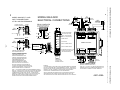
wires. TC inputs require two small jumpers at the input terminals
to select upscale or downscale break detection (see Drawing
4501-639). Before calibrating an input, be sure that these
jumpers are either configured or removed, as required by your
application. Small measurement errors may occur if the jumpers
are changed after input calibration. Factory units are calibrated
and shipped without these jumpers. Be sure to remove power
and/or disable the load before unplugging the terminals to
uninstall the module, installing or removing jumpers, or before
attempting service. All connections must be made with power
removed.
WARNING: For compliance to applicable safety and
performance standards, the use of shielded cable is
recommended as shown in Drawing 4501-639. Further, the
application of earth ground must be in place as shown in
Drawing 4501-639. Failure to adhere to sound wiring and
grounding practices may compromise safety & performance.
3.0 MODULE CONFIGURATION
The alarm module needs to be configured for your specific
application. Complete configuration is done using Acromag’s
Windows 95® or NT® Configuration Program and the IntelliPack
Serial Port Adapter. Configuration details are included in Alarm
Configuration Manual 8500-563. Limited field configuration via
the module’s push-buttons and LED’s is covered below.
FIELD CONFIGURATION
CAUTION: Risk of Electric Shock - More than one disconnect
switch may be required to de-energize the equipment before
servicing.
This program mode allows adjustment to key alarm
parameters in the field, without having to connect a host
computer. Field reprogrammability is accomplished via the alarm
module’s “SET” and “MODE” push buttons and LED’s (see
Drawing 4501-631). Field reconfiguration via these controls will
vary depending on the alarm function (see Table 5).
1. Power: Refer to Electrical Connections Drawing 4501-639.
Variations in power supply voltage within rated limits has
negligible effect on module accuracy. For supply
connections, use No. 14 AWG wires rated for at least 75°C.
The power terminal is diode-coupled for reverse polarity
protection.
Equipment Required
•
2. Inputs: Connect input(s) per Electrical Connections Drawing
4501-639. Observe proper polarity when making connections
(see label for input type). Input-to-input isolation is limited to
within the common-mode voltage range (up to 48V). Note
that TC inputs require two small jumper wires at the input
terminals to select upscale or downscale break detection. Be
sure that these jumpers are either configured or removed, as
required by your application and before attempting
calibration. Small offset errors may occur if the jumpers are
changed after input calibration.
An accurate input millivoltage source or thermocouple
calibrator adjustable over the range required for setpoint and
dropout (deadband). Note: For best results, the input
source must be accurate beyond the required specifications.
For voltage inputs, use a voltage source with an output
impedance of 100Ω or less.
General Field Programming Procedure
The following procedure uses the corresponding relay LED
indicators (constant ON or FLASHING) to indicate which relay
parameters (relay 1 or 2) are being modified (see Table 5).
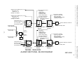
3. Output Contacts: Wire relay contacts as shown in Electrical
Connections Drawing 4501-639. See the “Alarm Relay
Specifications” for power capacity. If necessary, an
interposing relay can be used to switch higher currents as
shown in Interposing Relay Connection Drawing 4501-634.
CAUTION: To avoid damage to the unit, do not insert sharp or
oversized objects into the push-button switch openings. When
depressing the push-buttons, use a blunt-tipped object and apply
pressure gradually until you feel or hear the tactile response.
1. Connect a precision voltage source or thermocouple
calibrator to the input, as required (see Drawing 4501-639).
2. Apply power and the module’s green “Run” LED will light.
3. Press and hold the “MODE” push button until the green
“Run” LED goes out, and the relay 1 LED turns on (see Table
5). In this mode, the unit is ready to accept an input for
parameter 1 of relay 1 per Table 3 below. If you do not wish
to change this parameter, skip to step 6.
4. Adjust the input source level for relay parameter 1 as shown
in Table 3 according to your alarm function.
Electromechanical Relay Contact Protection: To
maximize relay life with inductive loads, external protection is
required. For DC inductive loads, place a diode across the
load (1N4006 or equivalent) with cathode to (+) and anode to
(-). For AC inductive loads, place a Metal Oxide Varistor
(MOV) across the load. See Relay Contact Protection
Drawing 4501-626 for details.
IMPORTANT: Noise and/or jitter on the input signal has the
effect of reducing (narrowing) the instrument’s deadband and
may produce contact chatter. The long term effect of this will
reduce the life of mechanical relays. To reduce this
undesired effect, you should increase the effective deadband.
Table 3: Relay Config Parameter 1 Per Alarm Function
ALARM FUNCTION
PARAMETER 1
Limit Alarm
High or Low Setpoint Value
Window Alarm
High Setpoint Value
On/Off Controller
Controller “On” Setpoint Value
Deviation Alarm
Set the Deviation Amount (Use
(Both Inputs Required) Proper Polarity between inputs)
Peak/Valley Detector
Peak/Valley Detect Start Value
Rate-of-Change Alarm Rate-Of-Change Threshold
4. Grounding: See Electrical Connections Drawing 4501-639.
The module housing is plastic and does not require an earth
ground connection. However, there are mounting positions
on the input terminals to connect a cable shield, plus earth
ground. These connections are isolated from the input circuit
and their use is recommended to minimize noise and help
protect the unit from potentially damaging input transients.
-5-