1
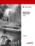
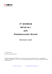
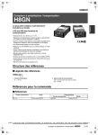
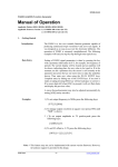
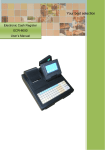
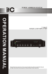
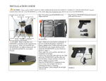
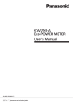
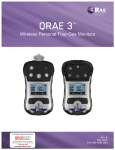
KLCNTKLCNT-A series Counter
KLCNT-A Series Counter
User Manual
Publication Release Data:September 19, 2007
Revision:1.0
For models:
:(this manual is only suitable for the items with frame and shadow)
)
KLCNT
-
①
① Series
A
Series A
②
③
② Power supply
④
⑤
⑥
⑦
③Led color
④ Input type
⑤ Output type
-
AC 220V
-
red
-
PNP
-
Contact output
D1
DC 12V
G6
green
N
NPN
T
Transistor output
D2
DC 24V
Y6
yellow
http://www.wxkldz.com
17 pages
⑥ Interface
-
⑦ Printer
None
-
None
232
RS-232
P
Serial Microprinter
422
RS-422
485
RS-485
Publication Release Date: September 19, 2007
Revision 1.0
KLCNTKLCNT-A series Counter
http://www.wxkldz.com
17 pages
Publication Release Date: September 19, 2007
Revision 1.0
KLCNTKLCNT-A series Counter
Table of contents
1. FEATURES ...................................................................................................................................................... 2
2. ORDING INFORMATION AND SPECIFICATIONS ................................................................................... 3
2.1 Ording Information................................................................................................................................... 3
2.2 Specifications ........................................................................................................................................... 3
2.2.1 Input Characteristics....................................................................................................................... 3
2.2.2 Output Characteristics.................................................................................................................... 3
2.2.3 Functions.......................................................................................................................................... 3
2.2.4 Ratings ............................................................................................................................................. 4
2.3 Internal Connections ............................................................................................................................... 4
2.3.1 Input Circuit...................................................................................................................................... 4
2.3.2 Output Circuit................................................................................................................................... 4
3. INTRODUCTION OF THE PANEL ............................................................................................................... 5
3.1 Indicator Lights ......................................................................................................................................... 5
3.2 Main Display ............................................................................................................................................. 5
3.3 Keys ........................................................................................................................................................... 5
4. OPERATION .................................................................................................................................................... 6
4.1 Recommanded Operation Procedure................................................................................................... 6
4.2 Meaning of the Characters Showing on the 7-seg Led...................................................................... 6
4.3 Overview of Function Parameters......................................................................................................... 7
4.3.1 Counting Modes .............................................................................................................................. 7
4.3.2 Output Modes .................................................................................................................................. 9
4.3.3 One-shot Output Time.................................................................................................................. 12
4.3.4 Counting Speed............................................................................................................................. 12
4.3.5 Decimal Point Position ................................................................................................................. 12
4.3.6 Prescale Value .............................................................................................................................. 12
4.4 To Modify a Parameter.......................................................................................................................... 13
4.5 Procedure of Running Mode ................................................................................................................ 14
4.6 Procedure of Function Setting Mode .................................................................................................. 15
4.7 Diagnosis on the Abnormal Display .................................................................................................... 16
5. DIMENSIONS AND EXTERNAL CONNECTIONS .................................................................................. 16
5.1 Dimensions ............................................................................................................................................. 16
5.2 External Connections ............................................................................................................................ 17
http://www.wxkldz.com
Page 1 of 17
Publication Release Date: September 19, 2007
Revision 1.0
KLCNTKLCNT-A series Counter
1. Features
Two input channels for high speed pluses (Max. 5kHz)
One input channel for external reset signal
Two digital output channels
Highly visible displays with six 7-seg leds
Counting range: 0 ~ 999999
Decimal point adjustable
7 counting modes
8 output modes
Prescaling function
One-shot output function (holding time can be set)
Present count value can be saved when power-off
Color of the leds can be selected according to the model ( red / green / yellow )
Input types can be selected according to the model ( NPN type / PNP type )
Output type can be selected according to the model ( contact output / transistor output )
Serial Communication type can be selected according to the model ( RS-232C / RS-422 / RS-485 )
Power supply can be selected accroding to the model ( AC 220V / DC 12V / DC 24V )
http://www.wxkldz.com
Page 2 of 17
Publication Release Date: September 19, 2007
Revision 1.0
KLCNTKLCNT-A series Counter
2. Ording Information and Specifications
2.1 Ording Information
KLCNT -
①
① Series
A
Series A
②
③
④
⑤
⑥
( Not all models here can be manufactured, please
contact with us first)
)
⑦
② Power supply
③ Led color
④ Input type
-
AC 220V
-
Red
-
PNP
-
⑤ Output type
Contact output
⑥ Interface
D1
DC 12V
G6
Green
N
NPN
T
Transistor output
D2
DC 24V
Y6
Yellow
-
⑦ Printer
None
-
None
232
RS-232C
P
Serial Microprinter
422
RS-422
485
RS-485
2.2 Specifications
2.2.1 Input Characteristics
No-voltage input(
(NPN type)
)
Input current when ON
Max. 10 mA
Residual voltage when ON
Max. 2.0V
Leakage current when OFF
Max. 0.1 mA
Voltage input(
(PNP type)
)
Input voltage
Max. DC 15V
Logic H
DC 6V~15V
Logic L
DC 0~2V
2.2.2 Output Characteristics
NPN open collector output
Rated load voltage
DC 24V
Load current
Max. 100 mA
Leakage current
Max. 100uA
2.2.3 Functions
Input
Display
Output
Max. counting speed
30 Hz or 5 kHz (selectable, ON/OFF ratio 1:1), common setting for CP1 and CP2
External reset singal
Minimum reset input signal width: 30 ms
Counting mode
UP-1, UP-2, DN-1, DN-2, UD-A, UD-B, UD-C
Input type
No-voltage input / voltage input, (can be selected according to the model)
display
Six 7-seg leds and six red led lights
Dimension of the led
10.2X5.8 mm
Color of the 7-seg leds
Red / green / yellow (can be selected according to the models)
digits
6 digits(000000 ~ 999999)
Decimal point position
Rightmost 3 digits
Display refresh period
About 50ms typically
Zero display
Leading zeros are not displayed
Oupput type
Transistor output / contact output (can be selected according to the models)
Delay in comparative outputs
Max. 50ms
Output mode
N, F, C, k-1, P, Q, A
One-shot output time
The one-shot output time can be set
External power supply
DC 12V(±10%) 100mA
Reset source
External, manual, and automatic reset (internal according to C, R, P, and Q mode operation)
Prescale Function
transfer the present count value into the form user needed
Memory backup
EEPROM (overwrites: 100,000 times min.) that can store data for 10 years min.
http://www.wxkldz.com
Page 3 of 17
Publication Release Date: September 19, 2007
Revision 1.0
KLCNTKLCNT-A series Counter
2.2.4 Ratings
Power
Supply
AC 220V
AC 220V ( ±10% ) , 50Hz / 60Hz
DC 12V
DC 12V ( ±10% )
DC 24V
DC 24V ( ±10% )
Power consumption
4.4 VA typically
Ambient temperature
( -10 ~ +45 )℃ ( with no icing or condensation )
Ambient humidity
25% to 85% ( with no condensation )
Storage temperature
( -15 ~ +55 )℃ ( with no icing or condensation )
2.3 Internal Connections
2.3.1 Input Circuit
No-voltage input ( NPN isolated type ):
Voltage input ( PNP isolated type ):
2.3.2 Output Circuit
NPN Open collector output type:
http://www.wxkldz.com
Page 4 of 17
Publication Release Date: September 19, 2007
Revision 1.0
KLCNTKLCNT-A series Counter
3. Introduction of the Panel
Panel of KLCNT-A series counter is shown as below:
①
②
①
① Indicator lights
③
② Main display
③ Keys
④
④ cover shell
3.1 Indicator Lights
Indicator lights
explanation
SV1(count)
Lit when displaying the Set Value 1 on the main display area
SV2(Set Value 2)
Lit when displaying the Set Value 2 on the main display area
SET(Set Value 1)
Lit when entering or working in the Function Setting Mode
OUT1
Lit during the period that OUT1 gives an output
OUT2
Lit during the period that OUT2 gives an output
R/S
Lit when the reset singal comes or in the course of serial conmmunication.
3.2 Main Display
Main display
Explanation
Showing the present count when all the indicator lights are off ;
Showing the Set Value 1 when the indicator light “SV1” is on
Showing the Set Value 2 when the indicator light “SV2” is on
Showing the present function parameter when the indicator light “SET” is on
Showing the value of present function parameter when the indicator light “SET” is on
3.3 Keys
key
Explanation
Mode key, to switch modes and function parameters
Tab key, to shift the present set bit
Up key, to increase the value of present function parameter
Enter key, to give a confirm / to save the present function parameter
http://www.wxkldz.com
Page 5 of 17
Publication Release Date: September 19, 2007
Revision 1.0
KLCNTKLCNT-A series Counter
4. Operation
After power-on, the counter enters Run mode and initialized with the parameters set last time, press Mode key to set the SV1 and SV2 .
Keeping Mode key pressed over 3 seconds to enter Function Setting Mode , in this mode all the function parameters can be modified. If
parameters are changed, the counter will be reset (present count value initialized and output turned OFF) on returning to Run mode.
Power-on
counting
To set SV1、
、SV2
Run Mode
stopped
over 3 seconds
over 3 seconds
to switch
Function Setting Mode
4.1 Recommanded Operation Procedure
Power on
Run Mode
Initialized with the function parameters set last time;
Press Mode key to look over or modify the values of SV1 and SV2;
***if looking over or modifying the function parameters are needed, keep Mode
key pressed over 3 seconds to enter the Function Setting Mode.
Function Setting Mode
To look over or modify the counting mode;
To look over or modify the output mode;
To look over or modify the one-shot output time;
To look over or modify the counting speed;
To look over or modify the decimal point position;
To look over or modify the prescale value;
***After operations, keep Mode key pressed over 3 seconds to return to Run
Mode
Run
4.2 Meaning of the Characters Showing on the 7-seg Led
0
1
2
3
4
5
6
7
8
9
A
b
C
d
E
F
G
H
i
J
k
L
m
n
o
p
q
r
S
t
U
v
w
y
Z
-
.
http://www.wxkldz.com
Page 6 of 17
Publication Release Date: September 19, 2007
Revision 1.0
KLCNTKLCNT-A series Counter
4.3 Overview of Function Parameters
The table below gives all the function parameters in setting mode, In the column “Value of menu”, the value
with frame and shadow means that it is the factory-set value of the present function parameter.
Function parameter
menu
Value of menu
Explanation
Counting Mode
UP-1/UP-2/dn-1/dn-2/Ud-A/Ud-b/Ud-C Used to select the counting mode
Output Mode
N / F /C / R / K-1 / P / Q / A
Used to select the output mode
One-shot Output time 1
HOLD / 0.01 ~ 99999
Used to set the one-shot output time of out1 channel
One-shot Output time 2
0.01 ~ 0.50 ~ 99999
Used to set the one-shot output time of out2 channel
Counting Speed
30Hz / 5KHz
Used to select counting speed
Decimal Point Position
------ / -----.- / ----.-- / ---.---
Used to decide decimal point position
PreScale Value
0.001 ~ 1.000 ~ 99.999
Used to set prescale value
4.3.1 Counting Modes
Counting mode
Explanation
Taking CP1 as Increment count input(Prohibit counting CP1 when CP2 is H)
Taking CP2 as increment count input(Prohibit counting CP2 when CP1 is L)
Taking CP1 as decrement count input(Prohibit counting CP1 when CP2 is H)
Taking CP2 as decrement count input(Prohibit counting CP2 when CP1 is L)
Command input mode, taking CP1 as count input, taking CP2 as command input
Individual input mode, taking CP1 as incremnet count input, taking CP2 as decrement count input
Quadrature input mode
UP-1 ( Increment ) Mode
CP1
H
L
CP2
H
L
t1
0
count
t1
Prohibit counting CP1
1
4
3
2
Taking CP1 as Increment count input
Prohibit counting CP1 when CP2 is H short
circuit
t1 must be greater than the minimum
signal width.
5
UP-2 ( Increment ) Mode
CP1
H
L
CP2
H
L
count
Prohibit counting CP2
t1
t1
0
1
http://www.wxkldz.com
2
3
4
Taking CP2 as increment count input
Prohibit counting CP2 when CP1 is L open
circuit
t1 must be greater than the minimum
signal width.
5
Page 7 of 17
Publication Release Date: September 19, 2007
Revision 1.0
KLCNTKLCNT-A series Counter
DN-1 ( Decrement ) Mode
CP1
H
L
CP2
H
L
t1
t1
Prohibit counting CP2
n
Taking CP1 as decrement count input
Prohibit counting CP1 when CP2 is H short
circuit
t1 must be greater than the minimum
signal width.
n-1
n-2
n-3
n-4
n-5
count
DN-2 ( Decrement ) Mode
CP1
H
L
CP2
H
L
Prohibit counting CP2
t1
t1
n
Taking CP2 as decrement count input
Prohibit counting CP2 when CP1 is L open
circuit
t1 must be greater than the minimum
signal width.
n-1
n-2
n-3
n-4
n-5
count
UP/DOWN A Command Input Mode
CP1
H
L
CP2
H
L
t1
t1
n
count
n +1
n +2
n +3
n +2
n +1
n +1
n
n +2
Taking CP1 as count input
Taking CP2 as command input
Count CP1 increaedly when CP2 is L
open circuit
Count CP1 decreaedly when CP2 is H
short circuit
t1 must be greater than the minimum
signal width.
UP/DOWN B Individual Input Mode
CP1
H
L
CP2
H
L
n
count
n +1
n +2
n +1
n +2
n +3
n+4
n +3
Taking CP1 as increment count input
Taking CP2 as decrement count input
CP1 and CP2 count individually
Count increasedly when the rising edge of
CP1 keeps ahead of which of CP2
Count decreasedly when the rising edge of
CP2 keeps ahead of which of CP1
t2 must be at least 1/2 the minimum
n +4
UP/DOWN C Quadrature Input Mode
CP1
H
L
H
L
CP2
signal width.
t2
计数
n
n +1
n +2
n +3
n +2
n +1
n
n +1
n +2
Note 1. Definitions of H & L:No-voltage input(H means shor circuit, L means open circuit); voltage input(H means DC 6~15V input,
L means DC 0~2V input).
Note 2. minimum signal width:16.7mS(when maxium counting speed = 30Hz)、100uS(when maxium counting speed = 5kHz)。
http://www.wxkldz.com
Page 8 of 17
Publication Release Date: September 19, 2007
Revision 1.0
KLCNTKLCNT-A series Counter
4.3.2 Output Modes
Mode
Explanation
As soon as the count reaches SV, the outputs and present value display are held until reset signal is input .
As soon as the count reaches SV, the present value display continues to increase/decrease. The outputs are held until reset
signal is input.
As soon as the count reaches SV, the present value display returns to the reset start status. The present value display does
not show the present value upon count-up. The outputs repeat one-shot operation. OUT1 self-holding output turns OFF after
the OUT2 one-shot.
As soon as the count reaches SV, the present value display returns to the reset start status after the one-shot output time.
The outputs repeat one-shot operation. OUT1 self-holding output turns OFF after the OUT2 one-shot output time.The OUT1
one-shot output time is independent of OUT2.
As soon as the count reaches SV, the present value display continues to increase/decrease until reset signal is inputed.
OUT1 self-holding output turns OFF after the OUT2 one-shot output time. The OUT1 one-shot output time is independent of
OUT2.
As soon as the count reaches SV, the present value display does not change during the one-shot output time period, but the
actual count returns to the reset start status, the outputs return to the start state and repeat the one-shot operation. OUT1
self-holding output turns off after the OUT2one-shot output time. The OUT1 one-shot output time is independent of OUT2.
As soon as the count reaches SV, the present value display continues to increase/decrease during the one-shot time and
returns to the reset start status after the one-shot output time. OUT1 self-holding output turns OFF after the OUT2 one-shot
output time.The OUT1 one-shot output time is independent of OUT2.
As soon as the count reaches SV, the present value display and OUT1 self-holding output is held until reset/reset 1 is input.
OUT1 and OUT2 are independent.
Explications are shown as the graphics below:
One-shot output of OUT1
Self-holding output
Self-holding output one-shot output of OUT2(0.01~99.99s)
Mode N As soon as the count reaches SV, the outputs and present value display are held until reset signal is input .
UP
DN
UP / DN
RESET
999999
SV2
SV1
0
OUT1
OUT2
Mode F As soon as the count reaches SV, the present value display continues to increase/decrease. The outputs are held until reset
signal is input.
UP
DN
UP / DN
RESET
999999
SV2
SV1
0
OUT1
OUT2
http://www.wxkldz.com
Page 9 of 17
Publication Release Date: September 19, 2007
Revision 1.0
KLCNTKLCNT-A series Counter
Mode C As soon as the count reaches SV, the present value display returns to the reset start status. The present value display does
not show the present value upon count-up. The outputs repeat one-shot operation. OUT1 self-holding output turns OFF after the OUT2
one-shot.output time.The OUT1
one-shot output time UP
DN
UP / DN
RESET
999999
SV2
SV1
0
OUT1
OUT2
Mode R As soon as the count reaches SV, the present value display returns to the reset start status after the one-shot output time. The
outputs repeat one-shot operation. OUT1 self-holding output turns OFF after the OUT2 one-shot output time.The OUT1 one-shot output
time is independent of OUT2.
UP
DN
UP / DN
reset
999999
SV2
SV1
0
OUT1
OUT2
Mode K-1 As soon as the count reaches SV, the present value display continues to increase/decrease until reset signal is inputed.
OUT1 self-holding output turns OFF after the OUT2 one-shot output time. The OUT1 one-shot output time is independent of OUT2.
UP
DN
UP / DN
RESET
999999
SV2
SV1
0
OUT1
OUT2
http://www.wxkldz.com
Page 10 of 17
Publication Release Date: September 19, 2007
Revision 1.0
KLCNTKLCNT-A series Counter
Mode P As soon as the count reaches SV, the present value display does not change during the one-shot output time period, but the
actual count returns to the reset start status, the outputs return to the start state and repeat the one-shot operation. OUT1 self-holding
output turns off after the OUT2one-shot output time. The OUT1 one-shot output time is independent of OUT2.
UP
DN
UP / DN
RESET
999999
SV2
SV1
0
OUT1
OUT2
Mode Q As soon as the count reaches SV, the present value display continues to increase/decrease during the one-shot time and
returns to the reset start status after the one-shot output time. OUT1 self-holding output turns OFF after the OUT2 one-shot output
time.The OUT1 one-shot output time is independent of OUT2.
UP
DN
UP / DN
RESET
999999
SV2
SV1
0
OUT1
OUT2
Mode A As soon as the count reaches SV, the present value display and OUT1 self-holding output is held until reset/reset 1 is input.
OUT1 and OUT2 are independent.
UP
DN
UP / DN
RESET
999999
SV2
SV1
0
OUT1
OUT2
Note 1. The full scale (FS) for KLCNT-A is 999999.
Note 2. When the present value reaches 999999, it returns to 0.
Note 3. If reset/reset 1 is input while one-shot output is ON, one-shot output turns OFF.
Note 5. If there is power failure while output is ON, output will turn ON again when the power supply has recovered. For one-shot output,
output will turn ON again for the duration of the output time setting once the power supply has recovered.
Note 6. Do not use the counter function in applications where the count may be completed (again) while one-shot output is ON.
Note 7. Range of set value : 0 ~ 999999。
http://www.wxkldz.com
Page 11 of 17
Publication Release Date: September 19, 2007
Revision 1.0
KLCNTKLCNT-A series Counter
4.3.3 One-shot Output Time
is used to control the one-shot output time of OUT1 (0.01~99.99 seconds). If modified to zero “0.00”, it is
displayed “HOLD”, and the output is held.
is used to control the one-shot output time of OUT2 (0.01~99.99 seconds). One-shot output can be used
only when C, R, K-1, P, Q, or A is selected as the output mode.
4.3.4 Counting Speed
Set the maximum counting speed (30Hz / 5kHz ) for CP1 and CP2 inputs together.
Explanation
In this mode , frequency of input pulse should be less than 30Hz
In this mode , frequency of input pulse should be less than 5kHz
4.3.5 Decimal Point Position
Change of this parameter will influence all the three values: the present count value, Set Value 1 and Set Value 2。
Explanation
The present count value, Set Value 1 and Set Value 2 are all integer
The present count value, Set Value 1 and Set Value 2 all have one point
The present count value, Set Value 1 and Set Value 2 all have one point
The present count value, Set Value 1 and Set Value 2 all have one point
4.3.6 Prescale Value
With prescale value, the present count value can be changed into the format that user needed. The range of the
prescale value is: 0.001 ~ 99.999.
For example: Using a KLCNT-A counter and an encoder to measure the distance (shown in the form: □□.□□m)
that the strap went across. As shown in the picture below, if the encoder output 25 pulses while the strap moved
across 0.5m, function settings below should be performed to the KLCNT-A counter:
① Set the decimal point position to 2 decimal places.
② Set the prescale value to 0.02 (0.5÷25).
0.5m
25 pulses
Encoder
http://www.wxkldz.com
Page 12 of 17
Publication Release Date: September 19, 2007
Revision 1.0
KLCNTKLCNT-A series Counter
4.4 To Modify a Parameter
Press
Mode to shift parameter (menu) display;
Press
Enter to show the value of the function parameter ( monitor state );
Press
Tab to the modification state;
Press
Tab to flicker the setting bit, to shift the setting bit, press
bit by one ( if over 9 then clear to 0 ).
Press
Enter to save the current value into the memory of the meter KLCNT-A and return to the
monitor state;
In monitor state and modification state, press
Monitor state
Up to increase the present set
Mode key to display parameter (menu).
Modification state (set bit flickering)
to shift set bit
to increase set bit
Next function parameter
http://www.wxkldz.com
Page 13 of 17
Publication Release Date: September 19, 2007
Revision 1.0
KLCNTKLCNT-A series Counter
4.5 Procedure of Running Mode
The chart below shows the procedure of Run Mode. Any time, keep Mode key
enter Function Setting Mode. Keep Up key
pressed over 3 seconds to
pressed over 3 seconds to enter the serial communicaion menu.
over 3 seconds
Present count value
Reset present
count value
over 1 seconds
cancel
Show Set Value 1
Modify Set Value 1
Press Enter to start
serial communication
Show Set Value 2
Modify Set Value 2
Lit during communication ,
return to the Run Mode
after communication is
over.
Run Mode
over 3 seconds
Procedure of Function Setting Mode
Function Setting Mode
Note 1.
.The fixed setting of serial communication: baudrate at 9600 bps , 8 transfer data bits, 1 stop bit, no parity error;
Note 2.
.The data and program of the serial communication transmitted need to be customized. If there is no program customized,
the KLCNT-A counter without serial microprinter will send the string “No serial communication program customized.” by the UART
port; while the KLCNT-A counter with serial microprinter will print the present count value (PCNT) and all the function parameters in
the form as below:
FUNCTION PARAMETERS
cntm: UP-1
outm: n
otm1: HOLD
otm2: 00.50 s
cnts: 30Hz
dP: -----pscl: 001.00
SV1: 100000
SV2: 200000
PCNT: 000000
http://www.wxkldz.com
Page 14 of 17
Publication Release Date: September 19, 2007
Revision 1.0
KLCNTKLCNT-A series Counter
4.6 Procedure of Function Setting Mode
The chart below shows the procedure of Function Setting mode. Any time, keep Mode key
pressed over 3
seconds to return to the Run mode, resetting the present count value and initializing with the parameters just
modified.
UP-1 / UP-2 / dN-1/ dN-2
Ud-A / Ud-B / Ud-C
over 3 seconds
n / F / C / r / k-1 / P / Q / A
Procedure
of
Run Mode
HOLD / 0.01 ~ 99999
Run Mode
0.01 ~ 0.50 ~ 99999
30HZ / 5KHZ
------ / -----.- / ----.-- / ---.---
0.001 ~ 1.000 ~ 99.999
Function Setting Mode
http://www.wxkldz.com
Page 15 of 17
Publication Release Date: September 19, 2007
Revision 1.0
KLCNTKLCNT-A series Counter
4.7 Diagnosis on the Abnormal Display
When an error occurs, error details will be displayed on the main display. Confirm the error from the main display
and take the appropriate disposal.
Main display
Indicator lights
Error contents
disposal
All off
SV1 or SV2 setting error
Press any key to set SV1 or SV2 again(SV1<=SV2)
All off
EEPROM memory error
Turn the power supply off and on again
All off
Serial communication error
To confirm the serial device, press Mode key to return to Run Mode
If problems can not be solved according to the disposal above, please contact with us.
5. Dimensions and External Connections
5.1 Dimensions
KLCNT-A series counters can be embeded as a panel meter, Dimension of the recommanded rectangular hole is
(92×46) mm.
Note: All units are in millimeters unless otherwise indicated.
http://www.wxkldz.com
Page 16 of 17
Publication Release Date: September 19, 2007
Revision 1.0
KLCNTKLCNT-A series Counter
5.2 External Connections
Caution
Be sure to check each terminal for correct number and polarity before connection;
Please use M3 crimp terminals;
Confirm that the power supply is turned off during connection;
Do not allow metal objects or conductive wires to enter the counter;
Wire signal lines and power lines separately to reduce electrical noise and interference;
Do not connect anything to unused terminals;
Confirm that the power supply meets specifications before use;
Do not touch the terminals while power is being supplied;
Do not lay heavy objects on the product during use or storage.
Definition of terminals
Termianl labels:
11
12
13
14
15
16
17
18
19
20
L
NC
N
NC
NC
NC
NC
NC
+12V
REV
1
2
3
4
5
6
7
8
9
10
OUT1
OUT2
GND
TXD
RXD
COM1
CP1
CP2
RST
COM2
Please refer to the section 2.3 and the chart below during installation and connection。
L
N
+12V
REV
11
12
13
14
15
16
17
18
19
20
1
2
3
4
5
6
7
8
9
10
GND
TXD
CP1
CP2
RST
COM2 OUT1 OUT2
Group
Power supply
Pulse input
Digital output
Terminal
RXD COM1
Label
Explanation
11
L
13
N
10
RST
External reset signal input
9
CP2
High speed pulse input channel 2
8
CP1
High speed pulse input channel 1
7
COM1
Reference ground of pulse input
3
OUT2
Open collector output channel 2
AC 220V power supply
2
OUT1
Open collector output channel 1
1
COM2
Reference ground of output
4
RXD
RS232 signal receive
RS-232 output
3
TXD
RS232 signal transmit
2
GND
Reference ground of RS-232 signal
External power supply
19
+12V
+12V external power supply, reference ground is termial 2
reserved
20
REV
http://www.wxkldz.com
Reserved, DO NOT BE CONNECTED
Page 17 of 17
Publication Release Date: September 19, 2007
Revision 1.0