1
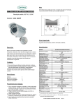
METS methane sensor S/N 1380 MANUAL UNDERWATER SENSORS FOR DISSOLVED GASES Franatech GmbH METS - Manual - METS - User Manual Release: Manual v9.2.1 April 2009 Sensor Parameters 27.03.2014 CONTENTS 1 READ ME FIRST -------------------------------------------------------------------------------------------------------2 1.1 1.2 1.3 1.4 1.5 W ARM-UP BEFORE DEPLOYMENT --------------------------------------------------------------------------------- 2 DRY-OUT BEFORE SWITCHING OFF ------------------------------------------------------------------------------- 2 OPERATIONAL CONSTRAINTS ------------------------------------------------------------------------------------- 2 STORAGE------------------------------------------------------------------------------------------------------------- 2 CHEMICAL AGGRESSION ------------------------------------------------------------------------------------------- 2 2 MECHANICAL SPECIFICATIONS---------------------------------------------------------------------------------3 3 INPUT / OUTPUT SPECIFICATIONS -----------------------------------------------------------------------------3 3.1 3.2 3.3 3.4 4 PIN CONFIGURATION------------------------------------------------------------------------------------------------ 3 CONSUMPTION: ----------------------------------------------------------------------------------------------------- 3 COMMUNICATION PROTOCOL FOR DIGITAL OUTPUT ----------------------------------------------------------- 4 CALIBRATION FORMULA -------------------------------------------------------------------------------------------- 5 MAINTENANCE --------------------------------------------------------------------------------------------------------6 4.1 4.2 4.3 4.4 CHECK OF THE METHANE DETECTOR ---------------------------------------------------------------------------- 6 SEAL RINGS ---------------------------------------------------------------------------------------------------------- 6 CONNECTOR --------------------------------------------------------------------------------------------------------- 6 CHECK AND REPLACEMENT OF THE MEMBRANE ---------------------------------------------------------------- 7 Contact Information Franatech GmbH In der Marsch 8 21339 Lüneburg Germany Tel: Fax: +49-4131-603884 +49-4131-603885 email: URL: [email protected] www.franatech.com 1 Franatech GmbH 1 METS - Manual Read me first 1.1 Warm-up before deployment After having been stored unplugged, the semi-conductor needs several days to stabilize (burning-in process). A rule of thumb is as many days of warm-up as days of storage, up to one week. Beyond one week storage unpowered, allow 7 days warm-up, whatever the storage duration. This can be monitored by the methane voltage output evolution during warm-up. It is therefore recommended before field deployment, to connect the sensor to the energy supply early enough prior to shipping, and unplug it just for the shipping. The sensor should be powered about ½ hour before being put to water. To save power if the sensor is run on batteries during measurements, it is possible to have the sensor warm-up connected to the main supply, then unplug it to connect to the battery supply. The short interruption should have no influence. The same goes after retrieval of the sensor, if power has to be switched back to main. If the sensor has been stored unpowered for several weeks, it is recommended to have it lie powered minimum 6 hours in water (in a bucket for instance), after the warm-up phase is completed. The sensor is calibrated at 100% relative humidity. Therefore the relative humidity should lie close to 100%. This is reached about 30 min. after the sensor is put into water the first time after a couple of days out of water. If the sensor has been dry for a shorter period, the humidity level is reached faster. 1.2 Dry-out before switching off After deployment it is recommended to let the sensor connected to the energy supply for about 15 min, before unplugging it. If the sensor has to be packaged, extend to 30 min. , to ensure that no humidity gets trapped into the detector room. 1.3 Operational constraints Maximum deployment depth is 4500 m (pressure tested at 500 bar) Depressurization: recommended max. vertical speed or pressure change rate: 2 m/s or from 250 to 1 bar in 20 – 30 min. Operational temperature range: -2°C to +60°C Response: Reaction time: 5 to 10 sec. t90-time: 5 to 30 min dependent on turbulences 1.4 Storage By risk of freezing, store dry packaged. DO NOT USE SILICA GEL. Protect the membrane, which must be free of scratches and punctures 1.5 Chemical aggression The following is valid for conditions underwater, in the laboratory and also during work on deck. Exposure to 1% H2S in air causes detector breakdown Exposure at 300 vppm H2S in air causes a signal equivalent to 10 vppm methane in air Below this, no significant interference Avoid exposure to silicone adhesive, soldering vapor, hair grooming material, hydrocarbons lubricants, oil and fuel, which might result in a drift of the detector Avoid long exposure to methane concentration above 10 mol/l. Beyond ½ hour at this concentration, the sensor might need a couple of hours to recover. This depends on the age and stress history of the detector. Longer exposure, in particular at or beyond saturation level can cause a drift. 2 Franatech GmbH 2 METS - Manual Mechanical Specifications Dimensions Housing diameter: Length overall: 49 mm 200 mm Weight approx.: in air in water 0,8 kg 0,5 kg Materials Titan Housing and Connector Connector Subconn © microcircular MCBH8M 3 3.1 Input / Output Specifications Pin configuration pin # configuration 1 positive supply 9 – 36 VDC 2 GND 3 NC description 1 8 2 3 7 4 NC 5 NC 6 GND 7 TxD(RS232) 8 RxD(RS232) 6 5 4 male face view Note: - both GND (pins 2 and 6) are connected together on the electronic board - temperature is measured inside the detector room 3.2 Consumption: 110 mA @ 12 VDC (switch-on peak max. 250 mA) 3 Franatech GmbH 3.3 METS - Manual Communication protocol for digital output RS232 9600 Baud rate, 8 Data Bits, 1 Stop Bit, no Parity Bit The sensor has a PIC-address set at A0 Single read To read the data, send the command: #A0/r A0 = Sensor address, /r = Carriage Return The sensor responses one time for example with: >1:0AF2 2:07FB 3:0714 4:0000 5:0000 6:0000 7:0000 8:0000 /r Continuous Mode To start the continuous mode, send the command: SA0/r The sensor responses every second for example with: >1:0AF2 2:07FB 3:0714 4:0000 5:0000 6:0000 7:0000 8:0000 /r To stop the continuous mode, send the command: sA0/r The sensor responses with: !A0/r If there was a break in the power supply, you have to start the continuous mode again. 3.4 Calculation The sensor output string is an ASCII code. The string includes 8 values in HEX-Code. The first value (in this case 0AF2) is the methane signal (frequency f), second (07FB) the temperature signal. The other values are not used. To get the temperature voltage you have to convert the hexadecimal code in decimal and multiply them with 5/4096. Example: 07FBh = 2043d -> 2043*5V/4096 = 2,494V To get the frequency f (methane) you have to convert the hexadecimal code in decimal and multiply them with 4. Example: 0AF2h = 2802d -> 2802*4 = 11208Hz 4 Franatech GmbH METS - Manual The Methane concentration is calculated with the Formula: Vt 1 1 c exp ln B0 B1 * exp * V B2 R A0 A1 * exp t A2 * D With f f R R 0 R1 * exp R3 * exp R2 R4 c= Methane concentration [µmol/l] f= frequency [Hz] Vt = temperature voltage [V] The temperature is calculated with t Vt * T 1 T 2 Ai, Bi, Ti, Ri and D are parameter. You get these with the Calibration sheet 3.5 Calibration formula Basically the calibration aims at providing a relation between the sensor signal output and the concentration of dissolved methane. It is carried out in a dedicated apparatus, which allows to prepare water with a known concentration of dissolved methane. Gas mixtures of methane in air at different concentrations are bubbled in a reasonably air-tight tank filled with water. Calibration is started at lowest concentration in order to avoid having to change the water after each measure. The water is circulated into a small chamber, to which the sensor-head is attached by means of a flange. It is possible to have the sensor directly in the mixing tank, however the water must be circulated or stirred by some means. Otherwise a dead layer could build itself right before the membrane, hampering methane diffusion. This can induce an important delay before equilibrium is reached. The different concentrations are obtained from commercial certified gas mixtures (methane in synthetic air). The water temperature is set at a definite value and maintained thermostatically. For each concentration the measurement is made first when relative humidity has set around 100% and when equilibrium is reached between the partial pressures of methane in the gas mixture and in the water. The signal output stays then level. The time needed to attain this is conditioned to the size of the tank. A water sample is taken, and analyzed with a gas-chromatograph using the Head-Space method. The concentration is calculated equivalent under standard (25 °C, 1 atm). The calibration is carried out at different concentrations (generally 5) and temperatures (generally 3). The conversion formula is obtained by a 3dimensional fitting between output voltage, concentration and temperature. The concentrations and temperatures are chosen first according to the ranges expected at the deployment location, second according to the degree of resolution which is needed. As a rule, the wider the range the poorer the resolution. Typical range limits are concentrations between 50 nmol/l and 10 mol/l, and temperatures between 2 and 20°C. The certificate with the calibration formula is provided on the next page. 5 Franatech GmbH 4 METS - Manual Maintenance NOTICE: opening the sensor (except to replace the membrane) without prior consulting and explicit authorization of Franatech leads to loss of guarantee. 4.1 Check of the methane detector The detector is a semi-conductor. Adsorption of hydrocarbons on the active layer leads to electron exchange with oxygen and thus to modification of the conductivity of the active layer, which the electronic converts into a voltage. The following gives a simple method to control if the sensor needs a recalibration: put the sensor in a bucket of methane-free water and leave it (always under power) equilibrate at a room temperature of max. 20°C. When the displayed or output sensor temperature has reached approximately 20°C, the displayed voltage value for methane should be approximately for S/N 1380 4.6V to 5.0V Values outside these ranges are signs of a probable drift if they are repeatedly observed. To check the functionality of the methane detector, use for instance a cigarette lighter. Let gas flow against the membrane or against the detector for less than a second. The signal should increase sharply within a few seconds. Notice that a too long exposure to such high gas concentrations as in the lighter will drive the detector into saturation, whereby it needs afterwards some time to return to background values. NOTE: As stressed in §1, a too long exposure might also causes a drift, therefore the gas-lighter check should be made only if there is a doubt regarding the sensor. It is recommended to recalibrate the sensor regularly. Conditioned to deployment conditions, we recommend between 6 and 12 months, in some cases the sensor stays stable for a longer time than 12 months. The semiconductors are ageing, depending on stress (extremely variable conditions of temperature, humidity, gas composition, methane concentrations, off/on time...). The calibration should be carried out by Franatech, as it disposes of the qualified personal and equipment. No guarantee can be given for calibration carried out by the user himself. 4.2 Seal rings Only the flange side-seal-ring should be lubricated (see § membrane replacement) 4.3 Connector According to manufacturer's recommendations: ensure the connectors are lubricated - the recommended lubricant is Molykote 44 Medium -but use sparingly. Half a match head dose per contact is adequate. 6 Franatech GmbH METS - Manual 4.4 Check and replacement of the membrane The membrane serves for the desorption of dissolved gasses out of the surrounding water into the gas phase containing the detectors. The diffusion is driven by Henry’s Law. The direction is conditioned to the concentration gradient between water and gas phase, and within the membrane itself. To clean the membrane it is not necessary to open the sensor. Do not scrape the surface, although the surface is quite robust it is advised to rinse with fresh water and eventually lightly dab with a fuzzfree tissue; oil-free compressed air may be used. Replacing the membrane is only necessary if damages like punctures or deep scratches are visible, or if the membrane is folded over at the edge of the flange. Eventual bulging is normal. When replacing the membrane avoid any contact with the detectors, avoid direct exposure of the detector room to dust, humidity and particles. Handle the membrane generally with care by holding it at the edge. Notice: after having been pressurized, the membrane surface does not have a shiny appearance any more. Gouges left by the seal rings are normal. The membrane seal-ring should be replaced if it looks deformed, heavily flattened, or shows wear or cracks. To replace the membrane proceed as follows loosen the 6 flange screws (metric, M3x8). Leave the head screws in place, do not loosen them remove flange screws leave head screws remove the flange by prying it open carefully. At the beginning it might be hard to pull, after a few mm, once the first seal-ring appear, it pulls out easily. Avoid slanting. pry open 7 Franatech GmbH METS - Manual Turning the sensor downwards allows all parts to fall out flange flange screws sensor head membrane sintered disc support disc The flange has a side seal-ring and a membrane seal-ring. membrane seal-ring side seal-ring note: only the side seal-rings should be lubricated. The membrane seal-ring should absolutely be mounted dry. Wipe the inside of the head-room carefully to remove grease and water drops. Be extremely careful not to touch the detector, or let particles, dust or water touch the sensor. wipe inside the head room carefully 7 Franatech GmbH METS - Manual Put back in place first the support ring, then the sintered disc, and finally a new membrane. Place the membrane as flat as possible (smooth with finger is possible) Align the flange to have the indentation covering the 3 head screws. Press the flange evenly gently down until it sits, avoid slanting. Take care to tighten the flange screws crosswise to avoid slanting. Notice: Do not overdrive. The screws should be driven to the point where they resist to further drive; then give eventually a further ¼-turn. If you hear or feel grinding or creaking stop at once, going farther might cause seizing or damage to the thread. If the sensor is to be stowed unused for several weeks or months, it is recommended to unmount the membrane, rinse it, dry it, and if no damage is visible, put it in place again as flat as possible. 8