
1
The EMC2 (Enhanced Machine Control)
User Handbook
The EMC Team
4th May 2006
1
This handbook is a work in progress. If you are able to help with writing, editing, or graphic
preparation please contact any member of the writing team or join and send an email to [email protected].
Copyright (c) 2000-6 LinuxCNC.org
Permission is granted to copy, distribute and/or modify this document under the terms of the
GNU Free Documentation License, Version 1.1 or any later version published by the Free Software
Foundation; with no Invariant Sections, no Front-Cover Texts, and one Back-Cover Text: "This EMC
Handbook is the product of several authors writing for linuxCNC.org. As you find it to be of value in
your work, we invite you to contribute to its revision and growth." A copy of the license is included in
the section entitled "GNU Free Documentation License". If you do not find the license you may order
a copy from Free Software Foundation, Inc. 59 Temple Place, Suite 330 Boston, MA 02111-1307
Contents
I Introduction & installing EMC2
8
1 The Enhanced Machine Control
1.1
1.2
1.3
1.4
Introduction . . . . . . . . . .
The Big CNC Picture . . . . . .
Computer Operating Systems
History of the Software . . . .
9
.
.
.
.
.
.
.
.
.
.
.
.
.
.
.
.
.
.
.
.
.
.
.
.
.
.
.
.
.
.
.
.
.
.
.
.
.
.
.
.
.
.
.
.
.
.
.
.
.
.
.
.
.
.
.
.
.
.
.
.
.
.
.
.
.
.
.
.
.
.
.
.
.
.
.
.
.
.
.
.
.
.
.
.
.
.
.
.
.
.
.
.
.
.
.
.
.
.
.
.
.
.
.
.
.
.
.
.
.
.
.
.
.
.
.
.
.
.
.
.
.
.
.
.
.
.
.
.
.
.
.
.
. 9
. 9
. 10
. 10
1.5 How the EMC2 Works . . . . . . . . . .
1.5.1 Graphical User Interfaces . . .
1.5.2 Motion Controller EMCMOT . .
1.5.3 Discrete I/O Controller EMCIO
.
.
.
.
.
.
.
.
.
.
.
.
.
.
.
.
.
.
.
.
.
.
.
.
.
.
.
.
.
.
.
.
.
.
.
.
.
.
.
.
.
.
.
.
.
.
.
.
.
.
.
.
.
.
.
.
.
.
.
.
.
.
.
.
.
.
.
.
.
.
.
.
.
.
.
.
.
.
.
.
.
.
.
.
.
.
.
.
.
.
.
.
.
.
.
.
.
.
.
.
.
.
.
.
.
.
.
.
.
.
.
.
.
.
.
.
11
11
12
13
1.5.4 Task Executor EMCTASK .
1.6 Thinking Like a Machine Operator
1.6.1 Modes of Operation . . . . .
1.6.2 Information Display . . . . .
.
.
.
.
.
.
.
.
.
.
.
.
.
.
.
.
.
.
.
.
.
.
.
.
.
.
.
.
.
.
.
.
.
.
.
.
.
.
.
.
.
.
.
.
.
.
.
.
.
.
.
.
.
.
.
.
.
.
.
.
.
.
.
.
.
.
.
.
.
.
.
.
.
.
.
.
.
.
.
.
.
.
.
.
.
.
.
.
.
.
.
.
.
.
.
.
.
.
.
.
.
.
.
.
.
.
.
.
.
.
.
.
.
.
.
.
14
15
16
16
1.7 Thinking Like An Integrator . . . . . . . . . . . .
1.7.1 Units . . . . . . . . . . . . . . . . . . . . . .
1.7.2 Some things we may not want to change.
1.7.3 Some things we will need to change. . . .
.
.
.
.
.
.
.
.
.
.
.
.
.
.
.
.
.
.
.
.
.
.
.
.
.
.
.
.
.
.
.
.
.
.
.
.
.
.
.
.
.
.
.
.
.
.
.
.
.
.
.
.
.
.
.
.
.
.
.
.
.
.
.
.
.
.
.
.
.
.
.
.
.
.
.
.
.
.
.
.
.
.
.
.
.
.
.
.
.
.
.
.
18
18
19
19
.
.
.
.
.
.
.
.
2 Installing the EMC2 software
21
2.1 Introduction . . . . . . . . . . . . . . . . . . . . . . . . . . . . . . . . . . . . . . . . . . . . 21
2.2 EMC Download Page . . . . . . . . . . . . . . . . . . . . . . . . . . . . . . . . . . . . . . . 21
2.3 EMC2 install script - the easy way to install . . . . . . . . . . . . . . . . . . . . . . . . . . 22
2.4 Manual installing using apt commands. . . . . . . . . . . . . . . . . . . . . . . . . . . . . 22
II Configuring EMC2
23
3 Introduction
25
3.1 What is HAL? . . . . . . . . . . . . . . . . . . . . . . . . . . . . . . . . . . . . . . . . . . . . 25
3.1.1 HAL is based on traditional system design techniques
3.1.1.1 Part Selection . . . . . . . . . . . . . . . . . . .
3.1.1.2 Interconnection Design . . . . . . . . . . . . .
3.1.1.3 Implementation . . . . . . . . . . . . . . . . . .
3.1.1.4 Testing . . . . . . . . . . . . . . . . . . . . . . .
.
.
.
.
.
.
.
.
.
.
.
.
.
.
.
.
.
.
.
.
.
.
.
.
.
.
.
.
.
.
.
.
.
.
.
.
.
.
.
.
.
.
.
.
.
.
.
.
.
.
.
.
.
.
.
.
.
.
.
.
.
.
.
.
.
.
.
.
.
.
.
.
.
.
.
.
.
.
.
.
25
25
25
26
26
3.1.2 Summary . . . . . . . . . . . . . . . . . . . . . . . . . . . . . . . . . . . . . . . . . . 26
3.2 HAL Concepts . . . . . . . . . . . . . . . . . . . . . . . . . . . . . . . . . . . . . . . . . . . 26
2
CONTENTS
3.3 HAL components . . . . . . . . . . . . . . . . .
3.3.1 External programs with HAL hooks . .
3.3.2 Internal Components . . . . . . . . . .
3.3.3 Hardware drivers . . . . . . . . . . . . .
3.3.4 Utilities . . . . . . . . . . . . . . . . . .
3.4 Tinkertoys, Erector Sets, Legos and the HAL
3.4.1 Tower . . . . . . . . . . . . . . . . . . .
3.4.2 Erector Sets . . . . . . . . . . . . . . . .
3.4.3 Tinkertoys . . . . . . . . . . . . . . . . .
3.4.4 A Lego Example . . . . . . . . . . . . .
3.5 Timing Issues In HAL . . . . . . . . . . . . . .
3.6 Dynamic Linking and Configuration . . . . .
4 HAL Tutorial
4.1 Before we start . . . . . . . . . . . . . . . . . .
4.1.1 Notation . . . . . . . . . . . . . . . . . .
4.1.2 Root Privilges . . . . . . . . . . . . . . .
4.1.3 The RTAPI environment . . . . . . . . .
4.2 A Simple Example . . . . . . . . . . . . . . . .
4.2.1 Loading a realtime component . . . . .
4.2.2 Examining the HAL . . . . . . . . . . .
4.2.3 Making realtime code run . . . . . . . .
4.2.4 Changing parameters . . . . . . . . . .
4.2.5 Saving the HAL configuration . . . . .
4.2.6 Restoring the HAL configuration . . . .
4.3 Looking at the HAL with halmeter . . . . . . .
4.3.1 Starting halmeter . . . . . . . . . . . .
4.3.2 Using halmeter . . . . . . . . . . . . . .
4.4 A slightly more complex example. . . . . . . .
4.4.1 Installing the components . . . . . . .
4.4.2 Connecting pins with signals . . . . . .
4.4.3 Setting up realtime execution - threads
4.4.4 Setting parameters . . . . . . . . . . . .
4.4.5 Run it! . . . . . . . . . . . . . . . . . . .
4.5 Taking a closer look with halscope. . . . . . .
4.5.1 Starting Halscope . . . . . . . . . . . .
4.5.2 Hooking up the “scope probes” . . . . .
4.5.3 Capturing our first waveforms . . . . .
4.5.4 Vertical Adjustments . . . . . . . . . . .
4.5.5 Triggering . . . . . . . . . . . . . . . . .
4.5.6 Horizontal Adjustments . . . . . . . . .
4.5.7 More Channels . . . . . . . . . . . . . .
3
.
.
.
.
.
.
.
.
.
.
.
.
.
.
.
.
.
.
.
.
.
.
.
.
.
.
.
.
.
.
.
.
.
.
.
.
.
.
.
.
.
.
.
.
.
.
.
.
.
.
.
.
.
.
.
.
.
.
.
.
.
.
.
.
.
.
.
.
.
.
.
.
.
.
.
.
.
.
.
.
.
.
.
.
.
.
.
.
.
.
.
.
.
.
.
.
.
.
.
.
.
.
.
.
.
.
.
.
. . . . . . . . .
. . . . . . . . .
. . . . . . . . .
. . . . . . . . .
. . . . . . . . .
. . . . . . . . .
. . . . . . . . .
. . . . . . . . .
. . . . . . . . .
. . . . . . . . .
. . . . . . . . .
. . . . . . . . .
. . . . . . . . .
. . . . . . . . .
. . . . . . . . .
. . . . . . . . .
. . . . . . . . .
and functions
. . . . . . . . .
. . . . . . . . .
. . . . . . . . .
. . . . . . . . .
. . . . . . . . .
. . . . . . . . .
. . . . . . . . .
. . . . . . . . .
. . . . . . . . .
. . . . . . . . .
.
.
.
.
.
.
.
.
.
.
.
.
.
.
.
.
.
.
.
.
.
.
.
.
.
.
.
.
.
.
.
.
.
.
.
.
.
.
.
.
.
.
.
.
.
.
.
.
.
.
.
.
.
.
.
.
.
.
.
.
.
.
.
.
.
.
.
.
.
.
.
.
.
.
.
.
.
.
.
.
.
.
.
.
.
.
.
.
.
.
.
.
.
.
.
.
.
.
.
.
.
.
.
.
.
.
.
.
.
.
.
.
.
.
.
.
.
.
.
.
.
.
.
.
.
.
.
.
.
.
.
.
.
.
.
.
.
.
.
.
.
.
.
.
.
.
.
.
.
.
.
.
.
.
.
.
.
.
.
.
.
.
.
.
.
.
.
.
.
.
.
.
.
.
.
.
.
.
.
.
.
.
.
.
.
.
.
.
.
.
.
.
.
.
.
.
.
.
.
.
.
.
.
.
.
.
.
.
.
.
.
.
.
.
.
.
.
.
.
.
.
.
.
.
.
.
.
.
.
.
.
.
.
.
.
.
.
.
.
.
.
.
.
.
.
.
.
.
.
.
.
.
.
.
.
.
.
.
.
.
.
.
.
.
.
.
.
.
.
.
.
.
.
.
.
.
.
.
.
.
.
.
.
.
.
.
.
.
.
.
.
.
.
.
.
.
.
.
.
.
.
.
.
.
.
.
.
.
.
.
.
.
.
.
.
.
.
.
.
.
.
.
.
.
.
.
.
.
.
.
.
.
.
.
.
.
.
.
.
.
.
.
.
.
.
.
.
.
.
.
.
.
.
.
.
.
.
.
.
.
.
.
.
.
.
.
.
.
.
.
.
.
.
.
.
.
.
.
.
.
.
.
.
.
.
.
.
.
.
.
.
.
.
.
.
.
.
.
.
.
.
.
.
.
.
.
.
.
.
.
.
.
.
.
.
.
.
.
.
.
.
.
.
.
.
.
.
.
.
.
.
.
.
.
.
.
.
.
.
.
.
.
.
.
.
.
.
.
.
.
.
.
.
.
.
.
.
.
.
.
.
.
.
.
.
.
.
.
.
.
.
.
.
.
.
.
.
.
.
.
.
.
.
.
.
.
.
.
.
.
.
.
.
.
.
.
.
.
.
.
.
.
.
.
.
.
.
.
.
.
.
.
.
.
.
.
.
.
.
.
.
.
.
.
.
.
.
.
.
.
.
.
.
.
.
.
.
.
.
.
.
.
.
.
.
.
.
.
.
.
.
.
.
.
.
.
.
.
.
.
.
.
.
.
.
.
.
.
.
.
.
.
.
.
.
.
.
.
.
.
.
.
.
.
.
.
.
.
.
.
.
.
.
.
.
.
.
.
.
.
.
.
.
.
.
.
.
.
.
.
.
.
28
28
28
29
29
29
29
29
30
30
31
32
.
.
.
.
.
.
.
.
.
.
.
.
.
.
.
.
.
.
.
.
.
.
.
.
.
.
.
.
33
33
33
33
34
34
34
35
36
37
38
38
38
39
39
42
42
43
44
46
46
46
46
49
50
51
51
53
54
III Using EMC2
55
5 Using The TKEMC Graphical Interface
57
CONTENTS
4
6 Using The MINI Graphical Interface
58
6.1 Introduction . . . . . . . . . . . . . . . . . . . . . . . . . . . . . . . . . . . . . . . . . . . . 58
6.2 Screen layout . . . . . . . . . . . . . . . . . . . . . . . . . . . . . . . . . . . . . . . . . . . . 59
6.3 Menu Bar . . . . . . . . . . . . . . . . . . . . . . . . . . . . . . . . . . . . . . . . . . . . . . 59
6.4 Control Button Bar . . . . . . . . . . . . . . . . . . . . . . . . . . . . . . . . . . . . . . . . 61
6.4.1 MANUAL . . . . . . . . . . . . . . . . . . . . . . . . . . . . . . . . . . . . . . . . . . . 61
6.4.2 AUTO . . . . . . . . . . . . . . . . . . . . . . . . . . . . . . . . . . . . . . . . . . . . 62
6.4.3 MDI . . . . . . . . . . . . . . . . . . . . . . . . . . . . . . . . . . . . . . . . . . . . . 63
6.4.4 [FEEDHOLD] – [CONTINUE] . . . . . . . . . . . . . . . . . . . . . . . . . . . . . . . 63
6.4.5 [ABORT] . . . . . . . . . . . . . . . . . . . . . . . . . . . . . . . . . . . . . . . . . . . 63
6.4.6 [ESTOP] . . . . . . . . . . . . . . . . . . . . . . . . . . . . . . . . . . . . . . . . . . . 63
6.5 Left Column . . . . . . . . . . . . . . . . . . . . . . . . . . . . . . . . . . . . . . . . . . . . . 64
6.5.1 Axis Position Displays . . . . . . . . . . . . . . . . . . . . . . . . . . . . . . . . . . . 64
6.5.2 Feedrate Override . . . . . . . . . . . . . . . . . . . . . . . . . . . . . . . . . . . . . 64
6.5.3 Messages . . . . . . . . . . . . . . . . . . . . . . . . . . . . . . . . . . . . . . . . . . 65
6.6 Right Column . . . . . . . . . . . . . . . . . . . . . . . . . . . . . . . . . . . . . . . . . . . . 65
6.6.1 Program Editor . . . . . . . . . . . . . . . . . . . . . . . . . . . . . . . . . . . . . . . 65
6.6.2 Backplot Display . . . . . . . . . . . . . . . . . . . . . . . . . . . . . . . . . . . . . . 65
6.6.3 Tool Page . . . . . . . . . . . . . . . . . . . . . . . . . . . . . . . . . . . . . . . . . . 66
6.6.4 Offset Page . . . . . . . . . . . . . . . . . . . . . . . . . . . . . . . . . . . . . . . . . 67
6.7 Keyboard Bindings . . . . . . . . . . . . . . . . . . . . . . . . . . . . . . . . . . . . . . . . . 67
6.7.1 Common Keys . . . . . . . . . . . . . . . . . . . . . . . . . . . . . . . . . . . . . . . 67
6.7.2 Manual Mode . . . . . . . . . . . . . . . . . . . . . . . . . . . . . . . . . . . . . . . . 68
6.7.3 Auto Mode . . . . . . . . . . . . . . . . . . . . . . . . . . . . . . . . . . . . . . . . . 68
6.8 Misc . . . . . . . . . . . . . . . . . . . . . . . . . . . . . . . . . . . . . . . . . . . . . . . . . 68
7 Machining Center Overview
69
7.1 Mechanical Components . . . . . . . . . . . . . . . . . . . . . . . . . . . . . . . . . . . . . 69
7.1.1 Linear Axes . . . . . . . . . . . . . . . . . . . . . . . . . . . . . . . . . . . . . . . . . 69
7.1.2 Rotational axes . . . . . . . . . . . . . . . . . . . . . . . . . . . . . . . . . . . . . . . 69
7.1.3 Spindle . . . . . . . . . . . . . . . . . . . . . . . . . . . . . . . . . . . . . . . . . . . 70
7.1.4 Coolant . . . . . . . . . . . . . . . . . . . . . . . . . . . . . . . . . . . . . . . . . . . 70
7.1.5 Pallet Shuttle . . . . . . . . . . . . . . . . . . . . . . . . . . . . . . . . . . . . . . . . 70
7.1.6 Tool Carousel . . . . . . . . . . . . . . . . . . . . . . . . . . . . . . . . . . . . . . . . 70
7.1.7 Tool Changer . . . . . . . . . . . . . . . . . . . . . . . . . . . . . . . . . . . . . . . . 70
7.1.8 Message Display . . . . . . . . . . . . . . . . . . . . . . . . . . . . . . . . . . . . . . 70
7.1.9 Feed and Speed Override Switches . . . . . . . . . . . . . . . . . . . . . . . . . . . 70
7.1.10Block Delete Switch . . . . . . . . . . . . . . . . . . . . . . . . . . . . . . . . . . . . 70
7.1.11Optional Program Stop Switch . . . . . . . . . . . . . . . . . . . . . . . . . . . . . . 70
7.2 Control and Data Components . . . . . . . . . . . . . . . . . . . . . . . . . . . . . . . . . . 70
7.2.1 Linear Axes . . . . . . . . . . . . . . . . . . . . . . . . . . . . . . . . . . . . . . . . . 70
7.2.2 Rotational Axes . . . . . . . . . . . . . . . . . . . . . . . . . . . . . . . . . . . . . . . 71
7.2.3 Controlled Point . . . . . . . . . . . . . . . . . . . . . . . . . . . . . . . . . . . . . . 71
7.2.4 Coordinate Linear Motion . . . . . . . . . . . . . . . . . . . . . . . . . . . . . . . . . 71
7.2.5 Feed Rate . . . . . . . . . . . . . . . . . . . . . . . . . . . . . . . . . . . . . . . . . . 71
7.2.6 Coolant . . . . . . . . . . . . . . . . . . . . . . . . . . . . . . . . . . . . . . . . . . . 72
CONTENTS
5
7.2.7 Dwell . . . . . . . . . . . . . . . . . . . . . . . . . . . . . . . . . . . . . . . . . . . . . 72
7.2.8 Units . . . . . . . . . . . . . . . . . . . . . . . . . . . . . . . . . . . . . . . . . . . . . 72
7.2.9 Current Position . . . . . . . . . . . . . . . . . . . . . . . . . . . . . . . . . . . . . . 72
7.2.10Selected Plane . . . . . . . . . . . . . . . . . . . . . . . . . . . . . . . . . . . . . . . 72
7.2.11Tool Carousel . . . . . . . . . . . . . . . . . . . . . . . . . . . . . . . . . . . . . . . . 72
7.2.12Tool Change . . . . . . . . . . . . . . . . . . . . . . . . . . . . . . . . . . . . . . . . . 72
7.2.13Pallet Shuttle . . . . . . . . . . . . . . . . . . . . . . . . . . . . . . . . . . . . . . . . 72
7.2.14Feed and Speed Override Switches . . . . . . . . . . . . . . . . . . . . . . . . . . . 73
7.2.15Path Control Mode . . . . . . . . . . . . . . . . . . . . . . . . . . . . . . . . . . . . . 73
7.3 Interpreter Interaction with Switches . . . . . . . . . . . . . . . . . . . . . . . . . . . . . . 73
7.3.1 Feed and Speed Override Switches . . . . . . . . . . . . . . . . . . . . . . . . . . . 73
7.3.2 Block Delete Switch . . . . . . . . . . . . . . . . . . . . . . . . . . . . . . . . . . . . 73
7.3.3 Optional Program Stop Switch . . . . . . . . . . . . . . . . . . . . . . . . . . . . . . 73
7.4 Tool File . . . . . . . . . . . . . . . . . . . . . . . . . . . . . . . . . . . . . . . . . . . . . . . 74
7.5 Parameters . . . . . . . . . . . . . . . . . . . . . . . . . . . . . . . . . . . . . . . . . . . . . 75
7.6 Coordinate Systems . . . . . . . . . . . . . . . . . . . . . . . . . . . . . . . . . . . . . . . . 75
8 Language Overview
77
8.1 Format of a line . . . . . . . . . . . . . . . . . . . . . . . . . . . . . . . . . . . . . . . . . . 77
8.2 Line Number . . . . . . . . . . . . . . . . . . . . . . . . . . . . . . . . . . . . . . . . . . . . 78
8.3 Word . . . . . . . . . . . . . . . . . . . . . . . . . . . . . . . . . . . . . . . . . . . . . . . . . 78
8.3.1 Number . . . . . . . . . . . . . . . . . . . . . . . . . . . . . . . . . . . . . . . . . . . 78
8.3.2 Parameter Value . . . . . . . . . . . . . . . . . . . . . . . . . . . . . . . . . . . . . . 79
8.3.3 Expressions and Binary Operations . . . . . . . . . . . . . . . . . . . . . . . . . . . 79
8.3.4 Unary Operation Value . . . . . . . . . . . . . . . . . . . . . . . . . . . . . . . . . . 80
8.4 Parameter Setting . . . . . . . . . . . . . . . . . . . . . . . . . . . . . . . . . . . . . . . . . 80
8.5 Comments and Messages . . . . . . . . . . . . . . . . . . . . . . . . . . . . . . . . . . . . . 80
8.6 Repeated Items . . . . . . . . . . . . . . . . . . . . . . . . . . . . . . . . . . . . . . . . . . . 80
8.7 Item order . . . . . . . . . . . . . . . . . . . . . . . . . . . . . . . . . . . . . . . . . . . . . . 81
8.8 Commands and Machine Modes . . . . . . . . . . . . . . . . . . . . . . . . . . . . . . . . . 81
8.9 Modal Groups
9 G Codes
. . . . . . . . . . . . . . . . . . . . . . . . . . . . . . . . . . . . . . . . . . . 81
83
9.1 G0: Rapid Linear Motion . . . . . . . . . . . . . . . . . . . . . . . . . . . . . . . . . . . . . 83
9.2 G1: Linear Motion at Feed Rate . . . . . . . . . . . . . . . . . . . . . . . . . . . . . . . . . 83
9.3 G2, G3: Arc at Feed Rate . . . . . . . . . . . . . . . . . . . . . . . . . . . . . . . . . . . . . 84
9.3.1 Radius format arcs . . . . . . . . . . . . . . . . . . . . . . . . . . . . . . . . . . . . . 84
9.3.2 Center format arcs . . . . . . . . . . . . . . . . . . . . . . . . . . . . . . . . . . . . . 84
9.4 G33: Spindle-Synchronized Motion . . . . . . . . . . . . . . . . . . . . . . . . . . . . . . . 85
9.5 G4: Dwell . . . . . . . . . . . . . . . . . . . . . . . . . . . . . . . . . . . . . . . . . . . . . . 86
9.6 G10: Set Coordinate System Data . . . . . . . . . . . . . . . . . . . . . . . . . . . . . . . . 86
9.7 G17, G18, G19: Plane Selection . . . . . . . . . . . . . . . . . . . . . . . . . . . . . . . . . 86
9.8 G21, G21: Length Units . . . . . . . . . . . . . . . . . . . . . . . . . . . . . . . . . . . . . . 86
9.9 G28, G30: Return to Home . . . . . . . . . . . . . . . . . . . . . . . . . . . . . . . . . . . . 86
9.10 G38.2: Straight Probe . . . . . . . . . . . . . . . . . . . . . . . . . . . . . . . . . . . . . . . 87
9.11 G40, G41, G42: Cutter Radius Compensation. . . . . . . . . . . . . . . . . . . . . . . . . 87
CONTENTS
6
9.12 G43, G49: Tool Length Offsets . . . . . . . . . . . . . . .
9.13 G53: Move in absolute coordinates . . . . . . . . . . . .
9.14 G54 to G59.3: Select Coordinate System . . . . . . . . .
9.15 G61, G61.1, G64: Set Path Control Mode . . . . . . . .
9.16 G80: Cancel Modal Motion . . . . . . . . . . . . . . . . .
9.17 G81 to G89: Canned Cycles . . . . . . . . . . . . . . . .
9.17.1Preliminary and In-Between Motion . . . . . . . .
9.17.2G81: Drilling Cycle . . . . . . . . . . . . . . . . . .
9.17.3G82: Drilling Cycle with Dwell . . . . . . . . . . .
9.17.4G83: Peck Drilling . . . . . . . . . . . . . . . . . .
9.17.5G84: Right-Hand Tapping . . . . . . . . . . . . .
9.17.6G85: Boring, No Dwell, Feed Out . . . . . . . . .
9.17.7G86: Boring, Spindle Stop, Rapid Out . . . . . .
9.17.8G87: Back Boring . . . . . . . . . . . . . . . . . .
9.17.9G88: Boring, Spindle Stop, Manual Out . . . . .
9.17.10
G89: Boring, Dwell, Feed Out . . . . . . . . . . .
9.17.11
G90, G99: Set Distance Mode . . . . . . . . . . .
9.18 G92, G92.1, G92.2, G92.3: Coordinate System Offsets
9.19 G93, G94: Set Feed Rate Mode . . . . . . . . . . . . . .
9.20 G98, G99: Set Canned Cycle Return Level . . . . . . . .
10 M Codes
10.1 M0, M1, M2, M30, M60: Program Stopping and
10.2 M3, M4, M5: Spindle Control . . . . . . . . . .
10.3 M6: Tool Change . . . . . . . . . . . . . . . . . .
10.4 M7, M8, M9: Coolant Control . . . . . . . . . .
10.5 M48, M49: Override Control . . . . . . . . . . .
10.6 M100 to M199: User Defined Commands . . .
Ending
. . . . .
. . . . .
. . . . .
. . . . .
. . . . .
.
.
.
.
.
.
.
.
.
.
.
.
.
.
.
.
.
.
.
.
.
.
.
.
.
.
.
.
.
.
.
.
.
.
.
.
.
.
.
.
.
.
.
.
.
.
.
.
.
.
.
.
.
.
.
.
.
.
.
.
.
.
.
.
.
.
.
.
.
.
.
.
.
.
.
.
.
.
.
.
.
.
.
.
.
.
.
.
.
.
.
.
.
.
.
.
.
.
.
.
.
.
.
.
.
.
.
.
.
.
.
.
.
.
.
.
.
.
.
.
.
.
.
.
.
.
.
.
.
.
.
.
.
.
.
.
.
.
.
.
.
.
.
.
.
.
.
.
.
.
.
.
.
.
.
.
.
.
.
.
.
.
.
.
.
.
.
.
.
.
.
.
.
.
.
.
.
.
.
.
.
.
.
.
.
.
.
.
.
.
.
.
.
.
.
.
.
.
.
.
.
.
.
.
.
.
.
.
.
.
.
.
.
.
.
.
.
.
.
.
.
.
.
.
.
.
.
.
.
.
.
.
.
.
.
.
.
.
.
.
.
.
.
.
.
.
.
.
.
.
.
.
.
.
.
.
.
.
.
.
.
.
.
.
.
.
.
.
.
.
.
.
.
.
.
.
.
.
.
.
.
.
.
.
.
.
.
.
.
.
.
.
.
.
.
.
.
.
.
.
.
.
.
.
.
.
.
.
.
.
.
.
.
.
.
.
.
.
.
.
.
.
.
.
.
.
.
.
.
.
.
.
.
.
.
.
.
.
.
.
.
.
.
.
.
.
.
.
.
.
.
.
.
.
.
.
.
.
.
.
.
.
.
.
.
.
.
.
.
.
.
.
.
.
.
.
.
.
.
.
.
.
.
.
.
.
.
.
.
.
.
.
.
.
.
.
.
.
.
.
.
.
.
.
.
.
.
.
.
.
.
.
.
.
.
.
.
.
.
.
.
.
.
.
.
.
.
.
.
.
.
.
.
.
.
.
.
.
.
.
.
.
.
.
.
.
.
.
.
.
.
.
.
.
.
.
.
.
.
.
.
.
.
.
.
.
.
.
.
.
.
.
.
.
.
.
.
.
.
.
.
.
.
.
.
.
.
.
87
87
88
88
88
88
89
90
91
91
91
91
92
92
92
92
92
93
93
94
.
.
.
.
.
.
95
95
95
96
96
96
96
11 O Codes
97
11.1 Subroutines: “sub”, “endsub”, “return”, “call” . . . . . . . . . . . . . . . . . . . . . . . . . 97
11.2 Looping: “do”, “while”, “endwhile”, “break”, “continue” . . . . . . . . . . . . . . . . . . . . 97
11.3 Conditional: “if”, “else”, “endif” . . . . . . . . . . . . . . . . . . . . . . . . . . . . . . . . . . 98
12 Other Codes
12.1 F: Set Feed Rate . . . . . . . . . . . . . . . . . . . . . . . . . . . . . . . . . . . . . . . . . .
12.2 S: Set Spindle Speed . . . . . . . . . . . . . . . . . . . . . . . . . . . . . . . . . . . . . . . .
12.3 T: Select Tool . . . . . . . . . . . . . . . . . . . . . . . . . . . . . . . . . . . . . . . . . . . .
13 Order of Execution
14 G-Code Best Practices
14.1 Use an appropriate decimal precision . . .
14.2 Use consistent white space . . . . . . . . .
14.3 Prefer “Center-format” arcs . . . . . . . . .
14.4 Put important modal settings at the top of
14.5 Don’t put too many things on one line . .
14.6 Don’t use line numbers . . . . . . . . . . .
99
99
99
99
100
. . . . .
. . . . .
. . . . .
the file
. . . . .
. . . . .
.
.
.
.
.
.
.
.
.
.
.
.
.
.
.
.
.
.
.
.
.
.
.
.
.
.
.
.
.
.
.
.
.
.
.
.
.
.
.
.
.
.
.
.
.
.
.
.
.
.
.
.
.
.
.
.
.
.
.
.
.
.
.
.
.
.
.
.
.
.
.
.
.
.
.
.
.
.
.
.
.
.
.
.
.
.
.
.
.
.
.
.
.
.
.
.
.
.
.
.
.
.
.
.
.
.
.
.
.
.
.
.
.
.
.
.
.
.
.
.
.
.
.
.
.
.
101
. 101
. 101
. 101
. 101
. 101
. 101
CONTENTS
15 Tool File and Compensation
7
102
15.1 Tool File . . . . . . . . . . . . . . . . . . . . . . . . . . . . . . . . . . . . . . . . . . . . . . . 102
15.2 Tool Compensation . . . . . . . . . . . . . . . . . . . . . . . . . . . . . . . . . . . . . . . . 103
15.3 Tool Length Offsets . . . . . . . . . . . . . . . . . . . . . . . . . . . . . . . . . . . . . . . . 103
15.4 Cutter Radius Compensation . . . . . . . . . . . . . . . . . . . . . . . . . . . . . . . . . . 104
15.4.1Cutter Radius Compensation Detail . . . . . . . . . . . . . . . . . . . . . . . . . . . 104
15.5 Tool Compensation Sources . . . . . . . . . . . . . . . . . . . . . . . . . . . . . . . . . . . 111
16 Coordinate System and G92 Offsets
113
16.1 Introduction . . . . . . . . . . . . . . . . . . . . . . . . . . . . . . . . . . . . . . . . . . . . 113
16.2 The Machine Position Command (G53) . . . . . . . . . . . . . . . . . . . . . . . . . . . . . 113
16.3 Fixture Offsets (G54-G59.3) . . . . . . . . . . . . . . . . . . . . . . . . . . . . . . . . . . . 113
16.3.1Default coordinate system . . . . . . . . . . . . . . . . . . . . . . . . . . . . . . . . 115
16.3.2Setting coordinate system values within G-code. . . . . . . . . . . . . . . . . . . . 115
16.4 G92 Offsets . . . . . . . . . . . . . . . . . . . . . . . . . . . . . . . . . . . . . . . . . . . . . 115
16.4.1The G92 commands . . . . . . . . . . . . . . . . . . . . . . . . . . . . . . . . . . . . 116
16.4.2Setting G92 values . . . . . . . . . . . . . . . . . . . . . . . . . . . . . . . . . . . . . 116
16.4.3G92 Cautions . . . . . . . . . . . . . . . . . . . . . . . . . . . . . . . . . . . . . . . . 117
16.5 Sample Program Using Offsets . . . . . . . . . . . . . . . . . . . . . . . . . . . . . . . . . . 117
A Glossary of Common Terms Used in the EMC Documents
119
A Legal Section
122
A.1 GNU Free Documentation License Version 1.1, March 2000 . . . . . . . . . . . . . . . . . 122
A.1.1 GNU Free Documentation License Version 1.1, March 2000 . . . . . . . . . . . . . 122
Part I
Introduction & installing EMC2
8
Chapter 1
The Enhanced Machine Control
1.1 Introduction
This book is intended for people who want to use the Enhanced Machine Controller to run a mill,
lathe, router, or to control some other rather standard kind of machine. Computer Numerical
Control or CNC is the general term used to name this kind of computer application. In order to
get right into the essential task of operating it we have limited the amount of information about
installation and setup. We assume that the user will install from one of the standard ways of install
(covered in Chapter 2). Machine wiring and setup is limited to what we refer to as a mini or benchtop
mill that is powered by stepper motors and amps that use a single parallel port.
If the user is interested in developing their own install using some other distribution of Linux or an
other operating system, or applying the EMC2 to a more complex machine, they should study the
Integrators Handbook where these topics are covered in greater detail.
1.2 The Big CNC Picture
The term CNC has taken on a lot of different meanings over the years. In the early days it replaced
the hands of a skilled machinist with motors that followed commands in much the same way that
the machinist turned the handwheels. From these early machines, a language of machine tool
control has grown. This language is called RS274 and several standard variants of it have been
put forward. It has also been expanded by machine tool and control builders in order to meet the
needs of specific machines. If a machine changed tools during a program it needed to have tool
change commands. If it changed pallets in order to load new castings, it had to have commands
that allowed for these kinds of devices as well. Like any language, RS274 has evolved over time.
Currently there are several dialects. In general each machine tool maker has been consistent within
their product line but different dialects can have commands that cause quite different behavior from
one machine to another.
More recently the language of CNC has been hidden behind or side-stepped by several programming
schemes that are referred to as “Conversational1 programming languages.” One common feature
of these kinds of programming schemes is the selection of a shape or geometry and the addition of
values for the corners, limits, or features of that geometry.
The use of Computer Aided Drafting has also had its affect upon the CNC programming languages.
Because CAD drawings are saved as a list or database of geometries and variables associated with
each, they are available to be interpreted into G-Code. These interpreters are called CAM (Computer
Aided Machining) programs.
Like the CAD converters, the rise of drawing programs, like CorelTM and the whole bunch of paint
programs, converters have been written that will take a bitmap or raster or vector image and turn
1 One machine tool manufacturer, Hurco, claims to have a right to the use of these programming schemes and to the use
of the term conversational when used in this context.
9
CHAPTER 1. THE ENHANCED MACHINE CONTROL
10
it into G-Code that can be run with a CNC.
You’re asking yourself, “Why did I want to know this?” The answer is that the EMC2 as is currently
exists does not directly take in CAD or any image and run a machine using it. It. The EMC2
uses a variant of the earlier CNC language named RS 274NGC. (Next Generation Controller). All
of the commands given to the EMC2 must be in a form that is recognized and have meaning to
the RS274NGC interpreter. This means that if you want to carve parts that were drawn in some
graphical or drafting program you will also have to find a converter that will transform the image
or geometry list into commands that are acceptable to the EMC2 interpreter. Several commercial
CAD/CAM programs are available to do this conversion. At least one converter (Ace) has been
written that carries a copyright that makes it available to the public.
There has been recent talk about writing a “conversational” or geometric interface that would allow
an operator to enter programs is much the same way that several modern proprietary controls enter
programs but it isn’t in there yet.
1.3 Computer Operating Systems
The EMC2 code can be compiled on almost any GNU-Linux Distribution (assuming it has been
patched with a real time extension). In addition to the raw code, some binary distributions are
available. The latest packages have been created around the Ubuntu GNU-Linux Distribution.
Ubuntu is one of the distributions that is aimed at novice Linux users, and has been found to be
very easy to use. Along with that, there are lots of places around the world, that offer support for it.
Installing emc2 on it is trivial, as you can see from Chapter 2.
The EMC2 will not run under a normal Microsoft (TM) operating system. The reason for this is
that the EMC2 requires a real-time environment for the proper operation of its motion planning
and stepper pulse outputs. Along with that, it also benefits from the much-needed stability and
performance of the Linux OS.
1.4 History of the Software
The EMC2 code was started by the Intelligent Systems Division at the National Institute of Standards
and Technology in the United States. The quotation below, taken from the NIST web presence some
time back, should lend some understanding of the essential reasons for the existence of this software
and of the NIST involvement in it.
As part of our (NIST) collaboration with the OMAC User’s Group, we have written software which implements real-time control of equipment such as machine tools, robots,
and coordinate measuring machines. The goal of this software development is twofold:
first, to provide complete software implementations of all OMAC modules for the purpose of validating application programming interfaces; and second, to provide a vehicle
for the transfer of control technology to small- and medium-sized manufacturers via the
NIST Manufacturing Extension Partnership. The EMC2 software is based on the NIST
Real-time Control System (RCS) Methodology, and is programmed using the NIST RCS
Library. The RCS Library eases the porting of controller code to a variety of Unix and
Microsoft platforms, providing a neutral application programming interface (API) to operating system resources such as shared memory, semaphores, and timers. The RCS
Library also implements a communication model, the Neutral Manufacturing Language,
which allows control processes to read and write C++ data structures throughout a single
homogeneous environment or a heterogeneous networked environment. The EMC2 software is written in C and C++, and has been ported to the PC Linux, Windows NT, and
Sun Solaris operating systems. When running actual equipment, a real-time version of
Linux is used to achieve the deterministic computation rates required (200 microseconds
is typical). The software can also be run entirely in simulation, down to simulations of
the machine motors. This enables entire factories of EMC2 machines to be set up and
run in a computer integrated manufacturing environment.
CHAPTER 1. THE ENHANCED MACHINE CONTROL
11
EMC has been installed on many machines, both with servo motors and stepper motors. Here is a
sampling of the earliest applications.
• 3-axis Bridgeport knee mill at Shaver Engineering. The machine uses DC brush servo motors
and encoders for motion control, and OPTO-22 compatible I/O interfaced to the PC parallel
port for digital I/O to the spindle, coolant, lube, and e-stop systems.
• 3-axis desktop milling machine used for prototype development. The machine uses DC brush
servo motors and encoders. Spindle control is accomplished using the 4th motion control axis.
The machine cuts wax parts.
• 4-axis Kearney & Trecker horizontal machining center at General Motors Powertrain in Pontiac,
MI. This machine ran a precursor to the full-software EMC2 which used a hardware motion
control board.
After these early tests, Jon Elson found the Shaver Engineering notes and replaced a refrigerator
sized Allen Bradley 7300 control on his Bridgeport with the EMC running on a Red Hat 5.2 distribution of Linux. He was so pleased with the result that he advertised the software on several news
groups. He continues to use that installation and has produced several boards that are supported
by the software.
From these early applications news of the software spread around the world. It is now used to control many different kinds of machines. More recently the Sherline company http://www.sherline.com
has released their first CNC mill. It uses a standard release of the EMC.
The source code files that make up the controller are kept in a repository on cvs.linuxcnc.org They
are available for anyone to download and use as they see fit. All EMC2 files (with some exceptions 2 )
carry a GPL or GPLD copyright. These files require that you make your source of them available to
your users. GPL copyright also requires that if you modify the code in that file and make a public
release of your revisions, you must return your modifications to the developers.
1.5 How the EMC2 Works
The Enhanced Machine Controller (EMC2) is a lot more than just another CNC mill program. It
can control machine tools, robots, or other automated devices. It can control servo motors, stepper
motors, relays,and other devices related to machine tools. In this handbook we focus on only a
small part of that awesome capability, the minimill.
Figure 1.1 shows a simple block diagram showing what a typical 3-axis EMC2 system might look
like. This diagram shows a stepper motor system. The PC, running Linux as it’s operating system,
is actually controlling the stepper motor drives by sending signals through the printer port. These
signals (pulses) make the stepper drives move the stepper motors. The EMC2 can also run servo
motors via servo interface cards or by using an extended parallel port to connect with external
control boards. As we examine each of the components that make up an EMC2 we will remind the
reader of this typical machine.
There are four main components to the EMC2 software: a motion controller (EMCMOT), a discrete
I/O controller (EMCIO), a task executor which coordinates them (EMCTASK), and a collection of
text-based or graphical user interfaces. An EMC2 capable of running a minimill must start some
version of all four of these components in order to completely control it. Each component is briefly
described below. In addition there is a layer called HAL (Hardware Abstraction Layer) which allows
simple reconfiguration of EMC2 without the need of recompiling.
1.5.1 Graphical User Interfaces
A graphical interface is the part of the EMC2 that the machine tool operator interacts with. The
EMC2 comes with several types of user interfaces:
2 some parts of emc2 are released under LGPL, to allow proprietary software to be linked together with emc2 (GUIs,
hardware drivers, etc.)
CHAPTER 1. THE ENHANCED MACHINE CONTROL
12
Figure 1.1: Typical EMC2 Controlled Machine
• an interactive command-line program named emcpanel
• a character-based screen graphics program named keystick 1.3
• X Windows programs named xemc 1.6 and yemc
• a Java-based GUI, emcgui
• two Tcl/Tk-based GUIs named tkemc 1.5 and mini 1.4.
• a modern GL-based GUI written in python called AXIS 1.23
Tkemc and Mini are most commonly used operator interfaces. They will run on Linux, Mac, and
Microsoft Windows if the Tcl/Tk programming language has been installed. The Mac and Microsoft
Windows version can connect to a real-time EMC2 running on a Linux machine via a network connection, allowing the monitoring of the machine from a remote location. Instructions for installing
and configuring the connection between a Mac or Microsoft Machine and a PC running the EMC2
can be found in the integrators handbook.
1.5.2 Motion Controller EMCMOT
Motion control includes sampling the position of the axes to be controlled, computing the next
point on the trajectory, interpolating between these trajectory points, and computing an output to
the motors. For servo systems, the output is based on a PID compensation algorithm. For stepper
systems, the calculations run open-loop, and pulses are sent to the steppers based on whether their
accumulated position is more than a pulse away from where their commanded position should be.
The motion controller includes programmable software limits, interfaces to hardware limit and home
switches.
3 AXIS
has been developed outside the EMC2 project, you can find information about it at http://axis.unpy.net
CHAPTER 1. THE ENHANCED MACHINE CONTROL
13
Figure 1.2: The AXIS Graphical Interface
The motion controller is written to be fairly generic. Initialization files (with the same syntax as
Microsoft Windows INI files) are used to configure parameters such as number and type of axes (e.g.,
linear or rotary), scale factors between feedback devices (e.g., encoder counts) and axis units (e.g.,
millimeters), servo gains, servo and trajectory planning cycle times, and other system parameters.
Complex kinematics for robots can be coded in C according to a prescribed function interface and
linked in to replace the default 3-axis Cartesian machine kinematics routines.
The motion controllers that you will be using with your stepper motors will most likely be stepgen.
The ability and requirements of each of these will be described when we get to hardware and how
to configure the EMC2 for your specific hardware.
1.5.3 Discrete I/O Controller EMCIO
Discrete I/O controllers are highly machine-specific, and are not customizable in general using
the INI file technique used to configure the more generic motion controller. However, since EMC2
uses the HAL, reconfiguration of the IO subsystem has become very powerful and flexible. EMC2
contains even a Programmable Logic Controller module (behaves just like a hardware PLC), which
can be used for very complex scenarios (tool changers, etc.).
In EMC2 there is only one big I/O controller, which provides support for all kinds of actions and
CHAPTER 1. THE ENHANCED MACHINE CONTROL
14
Figure 1.3: The Keystick interface
hardware control. All it’s outputs and inputs are HAL logic items (more on this later on), so you can
use only the subset which interests you (or the one that fist on your hardware output: e.g. if you
have only one parallel port, and no additional I/O cards).
1.5.4 Task Executor EMCTASK
The Task Executor is responsible for interpreting G and M code programs whose behavior does
not vary appreciably between machines. G-code programming is designed to work like a machinist
might work. The motion or turns of a handwheel are coded into blocks. If a machinist wanted his
mill to move an inch in the +X direction at some feedrate, he might slowly turn the handwheel five
turns clockwise in 20 seconds. The same machinist programming that same move for CNC might
write the following block of code.
G1 F3 X1.000
G1 means that the machine is supposed to run at a programmed feedrate rather than at the fastest
speed that it can. (G0) The F3 means that it should travel at 3 inches a minute or 3 millimeters a
minute if it is working in metric mode. The X1.000 assumes that the machine started at zero and
is supposed to go one inch in the positive direction. You will read quite a bit more about G-code in
the programming chapters.
Figure 1.7 is a block diagram of how a personal computer running the EMC2 is used to control
a machine with G-code. The actual G-code can be sent using the MDI (Machine Device Interface)
CHAPTER 1. THE ENHANCED MACHINE CONTROL
15
Figure 1.4: The Mini Graphical Interface
mode or it can be sent as a file when the machine is in Auto mode. These choices are made by the
operator and entered using one of the Graphical User Interfaces available with the software.
G-code is sent to the interpreter which compares the new block with what has already been sent
to it. The interpreter then figures out what needs to be done for the motion and input or output
systems and sends blocks of canonical commands to the task and motion planning programs.
1.6 Thinking Like a Machine Operator
This book will not even pretend that it can teach you to run a mill or a lathe. Becoming a machinist
takes time and hard work. An author once said, “We learn from experience, if at all.” Broken tools,
gouged vices, and scars are the evidence of lessons taught. Good part finish, close tolerances, and
careful work are the evidence of lessons learned. No machine, no computer program, can take the
place of human experience.
As you begin to work with the EMC2 program, you will need to place yourself in the position of
operator. You need to think of yourself in the role of the one in charge of a machine. It is a machine
that is either waiting for your command or executing the command that you have just given it.
Throughout these pages we will give information that will help you become a good operator of the
EMC2 mill. You will need some information right up front here so that the following pages will make
sense to you.
CHAPTER 1. THE ENHANCED MACHINE CONTROL
16
Figure 1.5: The TkEmc Graphical Interface
1.6.1 Modes of Operation
When an EMC2 is running, there are three different major modes used for inputting commands.
These are Manual, Auto, and MDI. Changing from one mode to another makes a big difference in
the way that the EMC2 behaves. There are specific things that can be done in one mode that can
not be done in another. An operator can home an axis in manual mode but not in auto or MDI
modes. An operator can cause the machine to execute a whole file full of G-codes in the auto mode
but not in manual or MDI.
In manual mode, each command is entered separate. In human terms a manual command might
be “turn on coolant” or “jog X at 25 inches per minute.” These are roughly equivalent to flipping a
switch or turning the handwheel for an axis. These commands are normally handled on one of the
graphical interfaces by pressing a button with the mouse or holding down a key on the keyboard.
In auto mode, a similar button or key press might be used to load or start the running of a whole
program of G-code that is stored in a file. In the MDI mode the operator might type in a block of
code and tell the machine to execute it by pressing the <return> or <enter> key on the keyboard.
Some motion control commands are available and will cause the same changes in motion in all
modes. These include ABOR T, ESTOP, and FEEDRATE OVERRIDE. Commands like these should be
self explanatory.
1.6.2 Information Display
While an EMC2 is running, each of the modules keeps up a dialog with each other and with the
graphical display. It is up to the display to select from that stream of information what the operator
needs to see and to arrange it on the screen in a way that makes it easy for the operator to understand. Perhaps the most important display is the mode the EMC2 is running in. You will want to
CHAPTER 1. THE ENHANCED MACHINE CONTROL
17
Figure 1.6: The XEMC Graphical Interface
keep your eye on the mode display.
Right up there with knowing what mode is active is consistent display of the position of each axis.
Most of the interfaces will allow the operator to read position based upon actual or commanded
position as well as machine or relative position.
Machine This is the position of an axis relative to the place where it started or was homed.
Relative This is the position of an axis after work or tool or other offsets have been applied.
Actual This is the real position of the axis within the machine or relative system.
Commanded This is where the axis is commanded to be.
These may all be exactly the same if no offsets have been applied and there is no deadband set
in the INI file. Deadband is a small distance which is assumed to be close enough – perhaps one
stepper pulse or one encoder pulse.
CHAPTER 1. THE ENHANCED MACHINE CONTROL
18
Figure 1.7: EMC2 Process Diagram
It is also important to see any messages or error codes sent by the EMC2. These are used by
operators if they need to be reminded to change a tool, to clear up problems in G-code programs, or
to find out why the machine stopped running.
As you work your way through this text, you will be learning, bit by bit how to setup and run
a machine with your copy of the EMC2 software. While you are learning about setting up and
running a minimill here, you will be thinking of other applications and other capabilities. These are
the topics of the other linuxcnc.org handbooks.
1.7 Thinking Like An Integrator
The biggest task of a machine integrator is figuring out how to connect a PC running the EMC2 to a
machine and configuring the software so that it runs the machine correctly. Most of this is not the
topic of this book but there are a few things that you will have to understand in order to make our
little minimill work for us like we expect it to work.
1.7.1 Units
Units can be confusing. A newbie recently asked, “Does it work in inches, feet, centimeters, millimeters, or what?” There are several possible answers to this question but the best one is that it
works in the units that you set it to work in.
At a machine level, we set each axis’ units to some value using an INI variable that looks like this.
CHAPTER 1. THE ENHANCED MACHINE CONTROL
19
UNITS = 1
or
UNITS =
0.03937007874016
Math folk will get a clue from these numbers because the long decimal number is the distance
represented by one millimeter if we convert it into inches. “So,” you say, “the EMC2 uses millimeters
internally.” If we use UNITS = 1 then we have defined our user units as millimeters. If we use UNITS
= 0.03937007874016 then we have defined our user units as inches. Using similar arithmetic we
could set our units to most any value we wanted. (Some of the EMC2 people who run vehicles with
the EMC2 set units to kilometers or miles.)
After we have decided upon a value for the units for an axis, we tell the EMC2 how may step pulses
or encoder pulses it should send or read for each unit of distance to be traveled. Once we have done
this, the EMC2 knows how to count units of distance. However it is very important to understand
that this counting of distance is different from the commanding of distance. You can command
distance in millimeters or inches without even thinking about the units that you defined. There are
G-codes that allow you to switch easily between metric and imperial.
1.7.2 Some things we may not want to change.
Within the EMC2 code are a few things that are not easily changed. We call these defaults. There
are connections that have been made between the running components of the EMC2 that we can
not easily change. We’ll see that there are displays and buttons and keyboard keys that are not
easily shifted about. We’ll learn about and get used to these in the chapters ahead.
1.7.3 Some things we will need to change.
The EMC2 is configured with files that are read at startup and used to override the compiled defaults. No real controller will likely use the compiled defaults, so you will certainly need to edit at
least some of these files to reflect the specifics of your machine.
There are five kinds of configuration files: INI, NML, TBL, VAR and HAL files. These are reflected in
lower case file extensions to a file name. They may be named EMC2.tbl or generic.tbl but they do the
same thing when they are read by the EMC2 as it starts up. Many users copy these and name them
for the specific machine that they are editing them for. A set of these files named Sherlinemill.ini,
Sherlinemill.var, Sherlinemill.tbl and Sherlinemill.nml are certainly more descriptive than a bunch
of files named generic.
These files each contain specific information for your CNC.
• stepper.ini, contains all the machine parameters such as servo gains, scale factors, cycle times,
units, etc. and will certainly need to be edited.
• emc.nml contains communication settings for shared memory and network ports you may
need to override on your system, although it is likely that you can leave these settings alone.
• stepper.tbl contains the tool information such as which pocket contains which tool, and the
length and diameter for each tool.
• rs274ngc.var contains variables specific to the RS-274-NGC dialect of NC code, notably for
setting the persistent numeric variables for the nine work coordinate systems.
We’ll get into some of the details of these files as we begin to hook up and operate our little machine.
In addition to these four files, there is a standard startup file. Back in the early days of the EMC it
was common to have to start up several different tasks in different terminal windows in order to get
the EMC to run a machine. Each of these tasks had to be supplied a bunch of information in the
CHAPTER 1. THE ENHANCED MACHINE CONTROL
20
form of arguments in order to be certain that the task started the way that we expected it to. All of
this was a tedious thing. All of this has been replaced with the run script file. It is named simply
’emc’. This executable script file controls the startup of all of the modules needed to run a standard
version of the EMC2. When run, it lets the user chose a certain config to run EMC2 from.
Chapter 2
Installing the EMC2 software
2.1 Introduction
One of the problems users often complained about EMC was installing the software itself. They
were forced to get sources, and compile themselves, and try to set up a RT-patched Linux, etc. The
developers of EMC2 chose to go with a standard distribution called Ubuntu1 .
Ubuntu has been chosen, because it fits perfectly into the Open Source views of EMC2:
• Ubuntu will always be free of charge, and there is no extra fee for the "enterprise edition", we
make our very best work available to everyone on the same Free terms.
• Ubuntu comes with full professional support on commercial terms from hundreds of companies around the world, if you need those services. Each new version of Ubuntu receives free
security updates for 18 months after release, some versions are supported for even longer.
• Ubuntu uses the very best in translations and accessibility infrastructure that the Free Software community has to offer, to make Ubuntu usable for as many people as possible.
• Ubuntu is released regularly and predictably; a new release is made every six months. You
can use the current stable release or help improve the current development release.
• The Ubuntu community is entirely committed to the principles of free software development;
we encourage people to use open source software, improve it and pass it on.
2.2 EMC Download Page
You will find the most recent releases of EMC2 announced on www.linuxcnc.org. The releases
of EMC2 will be done in two ways (sources and binary package). The sources (described in the
Developers Handbook) consist of a tarball (emc2-version.tar.gz), which you should download and
unpack into your home directory.
This document (oriented towards the end-user) will only try to explain how to install the binary
package on the Ubuntu distribution2 .
1 “Ubuntu” is an ancient African word, meaning “humanity to others”. Ubuntu also means “I am what I am because of
who we all are”. The Ubuntu Linux distribution brings the spirit of Ubuntu to the software world. You can read more about
it at http://www.ubuntu.com
2 For information regarding other Linux variants, check the Developers Handbook or ask for help on the emc-developers
mailing list http://sourceforge.net/mail/?group_id=6744.
21
CHAPTER 2. INSTALLING THE EMC2 SOFTWARE
22
2.3 EMC2 install script - the easy way to install
Chris Radek put together a simple script to install emc2 on Ubuntu. It runs the commands explained in 2.4.
To use it you need to :
• Download the script from http://www.linuxcnc.org/emc2-install.sh
• Save it on your Desktop. Right-click the icon, select Properties. Go to the Permissions tab and
check the box for Owner: Execute. Close the Properties window.
• Now double-click the emc2-install.sh icon, and select "Run in Terminal". A terminal will appear
and you will be asked for your password.
• When the installation asks if you are sure you want to install the EMC2 packages, hit Enter to
accept. Now just allow the install to finish.
• When it is done, you must reboot (System > Log Out > Restart the Computer), and when you
log in again you can run EMC2 by selecting it on the Applications > Other menu.
• If you aren’t ready to set up a machine configuration, try the sim-AXIS configuration; it runs a
"simulated machine" that requires no attached hardware.
• Now that the initial installation is done, Ubuntu will prompt you when updates of EMC2 or its
supporting files are available. When they are, you can update them easily and automatically
with the Update Manager.
2.4 Manual installing using apt commands.
The following few section will describe how to install EMC2 using a console and apt-commands. If
you know a bit about Linux and Debian-flavored distributions this might be trivial. If not, you might
consider reading 2.3.
First add the repository to /etc/apt/sources.list:
$ sudo sh -c ’echo "deb http://dsplabs.cs.upt.ro/emc2/ breezy emc2" > >/etc/apt/sources.list; echo "deb-src http://dsplabs.c
Then update & get emc2-axis.
$ sudo apt-get update
$ sudo apt-get install emc2-axis
This command will install the emc2-axis3 package along with all dependencies4 .
You might get warnings that the packages are from an untrusted source (this means your computer doesn’t recognize the GPG signature on the packages). To correct that issue the following
commands:
$ gpg --keyserver pgpkeys.mit.edu --recv-key BC92B87F
$ gpg -a --export BC92B87F | sudo apt-key add -
3 The
emc2-axis package is the AXIS gui packaged for emc2.
dependencies are one of the nicest thing in Debian based distributions. They assure you have everything installed
that you need. In the case of emc2 it’s even a RT-patched kernel, and all needed libraries.
4 The
Part II
Configuring EMC2
23
24
Chapter 3
Introduction
3.1 What is HAL?
HAL stands for Hardware Abstraction Layer. At the highest level, it is simply a way to allow a
number of “building blocks” to be loaded and interconnected to assemble a complicated system.
The “Hardware” part is because HAL was originally designed to make it easier to configure EMC for
a wide variety of hardware devices. Many of the building blocks are drivers for hardware devices.
However, HAL can do more than just configure hardware drivers.
3.1.1 HAL is based on traditional system design techniques
HAL is based on the same principles that are used to design hardware circuits and systems, so it is
useful to examine those principles first.
Any system (including a CNC machine), consists of interconnected components. For the CNC
machine, those components might be the main controller, servo amps or stepper drives, motors,
encoders, limit switches, pushbutton pendants, perhaps a VFD for the spindle drive, a PLC to run
a toolchanger, etc. The machine builder must select, mount and wire these pieces together to make
a complete system.
3.1.1.1 Part Selection
The machine builder does not need to worry how each individual part works. He treats them as
black boxes. During the design stage, he decides which parts he is going to use - steppers or
servos, which brand of servo amp, what kind of limit switches and how many, etc. The integrator’s
decisions about which specific components to use is based on what that component does and the
specifications supplied by the manufacturer of the device. The size of a motor and the load it must
drive will affect the choice of amplifier needed to run it. The choice of amplifier may affect the
kinds of feedback needed by the amp and the velocity or position signals that must be sent to the
amp from a control.
In the HAL world, the integrator must decide what HAL components are needed. Usually every
interface card will require a driver. Additional components may be needed for software generation
of step pulses, PLC functionality, and a wide variety of other tasks.
3.1.1.2 Interconnection Design
The designer of a hardware system not only selects the parts, he also decides how those parts will
be interconnected. Each black box has terminals, perhaps only two for a simple switch, or dozens
for a servo drive or PLC. They need to be wired together. The motors get connected to the servo
amps. The limit switches connect to the controller, and so on. As the machine builder works on the
design, he creates a large wiring diagram that shows how all the parts should be interconnected.
25
CHAPTER 3. INTRODUCTION
26
When using HAL, components are interconnected by signals. The designer must decide which
signals are needed, and what they should connect.
3.1.1.3 Implementation
Once the wiring diagram is complete it is time to build the machine. The pieces need to be
acquired and mounted, and then they are interconnected according to the wiring diagram. In a
physical system, each interconnection is a piece of wire, that needs to be cut and connected to the
appropriate terminals.
HAL provides a number of tools to help “build” a HAL system. Some of the tools allow you to
“connect” (or disconnect) a single “wire”. Other tools allow you to save a complete list of all the
parts, wires, and other information about the system, so that it can be “rebuilt” with a single
command.
3.1.1.4 Testing
Very few machines work right the first time. While testing the builder may use a meter to see if a
limit switch is working, or to measure the DC voltage going to a servo motor. He may hook up an
oscilloscope to check the tuning of a drive, or to look for electrical noise. He may find a problem
that requires the wiring diagram to be changed - perhaps a part needs to be connected differently
or replaced with something completely different.
HAL provides the software equivalent of a voltmeter, oscilloscope, signal generator, and other tools
for testing and tuning a system. The same commands used to build the system can be used to
make changes as needed.
3.1.2 Summary
This document is aimed at people who already know how to do this kind of hardware system
integration, but who do not know how to connect the hardware to EMC.
The traditional hardware design as described above ends at the edge of the main control. Outside
the control are a bunch of relatively simple boxes, connected together to do whatever is needed.
Inside, the control is a big mystery – one huge black box that we hope works.
HAL extends this traditional hardware design method to the inside of the big black box. It makes
device drivers and even some internal parts of the controller into smaller black boxes, that can be
interconnected and even replaced just like the external hardware. It allows the "system wiring
diagram" to show part of the internal controller, rather than just a big black box. And most
importantly it allows the integrator to test and modify the controller using the same methods he
would use on the rest of the hardware.
Terms like motors, amps, and encoders are familiar to most machine integrators. When we talk
about using extra flexible eight conductor shielded cable to connect an encoder to the servo input
board in the computer, the reader immediately understands what it is and is led to the question,
“what kinds of connectors will I need to make up each end.” The same sort of thinking is essential
for the HAL but the specific train of thought may take a bit to get on track. Using HAL words may
seem a bit strange at first, but the concept of working from one connection to the next is the same.
This idea of extending the wiring diagram to the inside of the controller is what HAL is all about. If
you are comfortable with the idea of interconnecting hardware black boxes, you will probably have
little trouble using HAL to interconnect software black boxes.
3.2 HAL Concepts
This section is a glossary that defines key HAL terms but it is a bit different than a traditional
glossary because these terms are not arranged in alphabetical order. They are arranged by their
relationship or flow in the HAL way of things.
CHAPTER 3. INTRODUCTION
27
Component: When we talked about hardware design, we referred to the individual pieces as "parts",
"building blocks", "black boxes", etc. The HAL equivalent is a "component" or "HAL component".
(This document uses "HAL component" when there is likely to be confusion with other kinds
of components, but normally just uses "component".) A HAL component is a piece of software
with well defined inputs, outputs, and behaviour, that can be installed and interconnected as
needed.
Parameter: Many hardware components have adjustments that are not connected to any other
components but still need to be accessed. For example, servo amps often have trim pots
to allow for tuning adjustments, and test points where a meter or scope can be attached to
view the tuning results. HAL components also can have such items, which are referred to
as "parameters". There are two types of parameters. Input parameters are equivalent to trim
pots - they are values that can be adjusted by the user, and remain fixed once they are set.
Output parameters cannot be adjusted by the user - they are equivalent to test points that
allow internal signals to be monitored.
Pin: Hardware components have terminals which are used to interconnect them. The HAL equivalent is a "pin" or "HAL pin". ("HAL pin" is used when needed to avoid confusion.) All HAL pins
are named, and the pin names are used when interconnecting them. HAL pins are software
entities that exist only inside the computer.
Physical_Pin: Many I/O devices have real physical pins or terminals that connect to external hardware, for example the pins of a parallel port connector. To avoid confusion, these are referred
to as "physical pins". These are the things that “stick out” into the real world.
Signal: In a physical machine, the terminals of real hardware components are interconnected by
wires. The HAL equivalent of a wire is a "signal" or "HAL signal". HAL signals connect HAL pins
together as required by the machine builder. HAL signals can be disconnected and reconnected
at will (even while the machine is running).
Type: When using real hardware, you would not connect a 24 volt relay output to the +/-10V
analog input of a servo amp. HAL pins have the same restrictions, which are based upon their
type. Both pins and signals have types, and signals can only be connected to pins of the same
type. Currently there are 8 types1 , as follows:
- a single TRUE/FALSE or ON/OFF value
•
BIT
•
FLOAT - a 32 bit floating point value, with approximately 24 bits of resolution and over 200 bits
of dynamic range.
•
U8
- an 8 bit unsigned integer, legal values are 0 to +255
•
S8
- an 8 bit signed integer, legal values are -128 to +127
•
U 16
- a 16 bit unsigned integer, legal values are 0 to +65535
•
S 16
- a 16 bit signed integer, legal values are -32768 to +32767
•
U 32
- a 32 bit unsigned integer, legal values are 0 to +4294967295
•
S 32
- a 32 bit signed integer, legal values are -2147483648 to +2147483647
Function: Real hardware components tend to act immediately on their inputs. For example, if
the input voltage to a servo amp changes, the output also changes automatically. However
software components cannot act "automatically". Each component has specific code that must
be executed to do whatever that component is supposed to do. In some cases, that code simply
runs as part of the component. However in most cases, especially in realtime components, the
code must run in a specific sequence and at specific intervals. For example, inputs should be
1 There has been some discussion about whether we really need all the integer types. Maybe they will be reduced or
eliminated later. Most signals and pins will be either floats or bits.
CHAPTER 3. INTRODUCTION
28
read before calculations are performed on the input data, and outputs should not be written
until the calculations are done. In these cases, the code is made available to the system in
the form of one or more "functions". Each function is a block of code that performs a specific
action. The system integrator can use "threads" to schedule a series of functions to be executed
in a particular order and at specific time intervals.
Thread: A "thread" is a list of functions that runs at specific intervals as part of a realtime task.
When a thread is first created, it has a specific time interval (period), but no functions. Functions can be added to the thread, and will be executed in order every time the thread runs.
For now a quick example will help get the concept across. We have a parport component named
hal_parport. That component defines one or more HAL pins for each physical pin. The pins are
described in that component’s doc section - their names, how each pin relates to the physical pin,
are they inverted, can you change polarity, etc. But that alone doesn’t get the data from the HAL
pins to the physical pins. It takes code to do that, and that is where functions come into the
picture. The parport component needs at least two functions. One to read the physical input pins
and update the HAL pins, the other to take data from the HAL pins and write it to the physical
output pins. Both of these functions are part of the parport driver.
3.3 HAL components
Each HAL component is a piece of software with well defined inputs, outputs, and behaviour, that
can be installed and interconnected as needed. This section lists available components and a brief
description of what they do. Complete details for each component are available later in this
document.
3.3.1 External programs with HAL hooks
motion A realtime module that accepts NML motion commands and interacts with HAL
iocontrol A user space module that accepts NML I/O commands and interacts with HAL
classicladder A PLC using HAL for all I/O
halui A user space program that interacts with HAL and sends NML commands (note: right now
experimental), it is intended to work as a full User Interface using external knobs & switches
3.3.2 Internal Components
stepgen Software step pulse generator with position loop. See section ??
freqgen Software step pulse generator. See section ??
encoder Software based encoder counter. See section ??
pid Proportional/Integral/Derivative control loops. See section ??
siggen A sine/cosine/triangle/square wave generator for testing. See section ??
supply a simple source for testing
blocks assorted useful components (mux, demux, or, and, integ, ddt, limit, wcomp, etc.)
CHAPTER 3. INTRODUCTION
29
3.3.3 Hardware drivers
hal_ax5214h A driver for the Axiom Measurement & Control AX5241H digital I/O board
hal_m5i20 Mesa Electronics 5i20 board
hal_motenc Vital Systems MOTENC-100 board
hal_parport PC parallel port. See section ??
hal_ppmc Pico Systems family of controllers (PPMC, USC and UPC)
hal_stg Servo To Go card (version 1 & 2)
hal_vti Vigilant Technologies PCI ENCDAC-4 controller
3.3.4 Utilities
halcmd Command line tool for configuration and tuning. See section ??
halgui GUI tool for configuration and tuning (not implemented yet).
halmeter A handy multimeter for HAL signals. See section ??
halscope A full featured digital storage oscilloscope for HAL signals. See section ??
Each of these building blocks is described in detail in later chapters.
3.4 Tinkertoys, Erector Sets, Legos and the HAL
A first introduction to HAL concepts can be mind boggling. Building anything with blocks can be a
challenge but some of the toys that we played with as kids can be an aid to building things with
the HAL.
3.4.1 Tower
I’m watching as my son and his six year old daughter build a tower from a box full of
random sized blocks, rods, jar lids and such. The aim is to see how tall they can make
the tower. The narrower the base the more blocks left to stack on top. But the narrower
the base, the less stable the tower. I see them studying both the next block and the shelf
where they want to place it to see how it will balance out with the rest of the tower.
The notion of stacking cards to see how tall you can make a tower is a very old and honored way of
spending spare time. At first read, the integrator may have gotten the impression that building a
HAL was a bit like that. It can be but with proper planning an integrator can build a stable system
as complex as the machine at hand requires.
3.4.2 Erector Sets2
What was great about the sets was the building blocks, metal struts and angles and plates, all with
regularly spaced holes. You could design things and hold them together with the little screws and
nuts.
2 The
Erector Set was an invention of AC Gilbert
CHAPTER 3. INTRODUCTION
30
I got my first erector set for my fourth birthday. I know the box suggested a much older
age than I was. Perhaps my father was really giving himself a present. I had a hard time
with the little screws and nuts. I really needed four arms, one each for the screwdriver,
screw, parts to be bolted together, and nut. Perseverence, along with father’s eventual
boredom, got me to where I had built every project in the booklet. Soon I was lusting
after the bigger sets that were also printed on that paper. Working with those regular
sized pieces opened up a world of construction for me and soon I moved well beyond the
illustrated projects.
Hal components are not all the same size and shape but they allow for grouping into larger units
that will do useful work.In this sense they are like the parts of an Erector set. Some components
are long and thin. They essentially connect high level commands to specific physical pins. Other
components are more like the rectangular platforms upon which whole machines could be built.
An integrator will quickly get beyond the brief examples and begin to bolt together components in
ways that are unique to them.
3.4.3 Tinkertoys3
Wooden Tinker toys had a more humane feel that the cold steel of Erector Sets. The heart
of construction with Tinker Toys was a round connector with eight holes equally spaced
around the circumference. It also had a hole in the center that was perpendicular to all
the holes around the hub.
Hubs were connected with rods of several different lengths. Builders would make large
wheels by using these rods as spokes sticking out from the center hub.
My favorite project was a rotating space station. Short spokes radiated from all the holes
in the center hub and connected with hubs on the ends of each spoke. These outer hubs
were connected to each other with longer spokes. I’d spend hours dreaming of living in
such a device, walking from hub to hub around the outside as it slowly rotated producing
near gravity in weightless space. Supplies traveled through the spokes in elevators that
transfered them to an from rockets docked at the center hub while they transfered their
precious cargos.
The idea of one pin or component being the hub for many connections is also an easy concept
within the HAL. Examples two and four (see section 4) connect the meter and scope to signals that
are intended to go elsewhere. Less easy is the notion of a hub for several incoming signals but that
is also possible with proper use of functions within that hub component that handle those signals
as they arrive from other components.
Another thought that comes forward from this toy is a mechanical representation of HAL threads.
A thread might look a bit like a centipede, caterpillar, or earwig. A backbone of hubs, HAL
components, strung together with rods, HAL signals. Each component takes in it own parameters
and input pins and passes on output pins and parameters to the next component. Signals travel
along the backbone from end to end and are added to or modified by each component in turn.
Threads are all about timing and doing a set of tasks from end to end. A mechanical
representation is available with Tinkertoys also when we think of the length of the toy as a
measure of the time taken to get from one end to the other. A very different thread or backbone is
created by connecting the same set of hubs with different length rods. The total length of the
backbone can be changed by the length of rods used to connect the hubs. The order of operations
is the same but the time to get from beginning to end is very diferent.
3.4.4 A Lego Example4
When Lego blocks first arrived in our stores they were pretty much all the same size and shape.
Sure there were half sized one and a few quarter sized as well but that rectangular one did most of
3 Tinkertoy
4 The
is now a registered trademark of the Hasbro company.
Lego name is a trademark of the Lego company.
CHAPTER 3. INTRODUCTION
31
the work. Lego blocks interconnected by snapping the holes in the underside of one onto the pins
that stuck up on another. By overlapping layers, the joints between could be made very strong,
even around corners or tees.
I watched my children and grandchildren build with legos – the same legos. There are a
few thousand of them in an old ratty but heavy duty cardboard box that sits in a corner
of the recreation room. It stays there in the open because it was too much trouble to put
the box away and then get it back out for every visit and it is always used during a visit.
There must be Lego parts in there from a couple dozen different sets. The little booklets
that came with them are long gone but the magic of building with interlocking pieces all
the same size is something to watch.
Notice the following description of building a set of motion components in the HAL and how much
like a wall of lego blocks it is.
The motion module exports a pin for each axis in cartesean space, and another pin for
each axis in joint space. When it is loaded, it automatically creates a "jumper" signal for
each axis, and automatically connects those signals from the joint pin to the cartesean
pin. So you automatically have "trivkins" as soon as you load the motion module. (trivkins
– trivial kinematics is the case where each motor moves a single axis at 90 degrees to the
others)
The motion module is like a pair of legos in a line end to end. Trivkins is just like a single block
overlapping the two. The in and out motion pins are plugged into each other by the block resting
above. But the parallel goes on.
If you need some other kinematics, you then load a specific kins component. This component "knows" the names of the pins that the motion module uses for each axis, both
joint and cartesean. When the module loads, it again automatically creates signals and
connects its own pins to the motion module’s pins (which will disconnect the "jumpers").
It could also know the thread names used by the motion module, and could automatically
add it’s own functions to those threads.
Trivkins is removed so that the motion blocks can be spread apart and by using other blocks, a
different bridge is built between input and output pins. In Lego terms, trivkins might be a gray
block and xxkins might be a yellow block.
So the net result is that 24 HAL signals and two HAL functions are configured, with no
action needed by the integrator other than loading the module. (24 signals are from 6
axis * 2 because we have joint and cartesean * 2 because we have forward and inverse
kinematics. Two functions because we have forward and inverse.) Because these HAL
signals exist, they can be metered or scoped or whatever for testing. But because both
modules know their names and know how to automatically connect them, the integrator
doesn’t have to know or care.
This kind of automatic HAL configuration is possible because all kinematics modules "plug in" the
same way.
3.5 Timing Issues In HAL
Threads is going to take a major intellectual push because unlike the physical wiring models
between black boxes that we have said that HAL is based upon, simply connecting two pins with a
hal-signal falls far short of the action of the physical case.
True relay logic consists of relays connected together, and when a contact opens or closes, current
flows (or stops) immediately. Other coils may change state, etc, and it all just "happens". But in
CHAPTER 3. INTRODUCTION
32
PLC style ladder logic, it doesn’t work that way. Usually in a single pass through the ladder, each
rung is evaluated in the order in which it appears, and only once per pass. A perfect example is a
single rung ladder, with a NC contact in series with a coil. The contact and coil belong to the same
relay.
If this were a conventional relay, as soon as the coil is energized, the contacts begin to open and
de-energize it. That means the contacts close again, etc, etc. The relay becomes a buzzer.
With a PLC, if the coil is OFF and the contact is closed when the PLC begins to evaluate the rung,
then when it finishes that pass, the coil is ON. The fact that turning on the coil opens the contact
feeding it is ignored until the next pass. On the next pass, the PLC sees that the contact is open,
and de-energizes the coil. So the relay still switches rapidly between on and off, but at a rate
determined by how often the PLC evaluates the rung.
In HAL, the function is the code that evaluates the rung(s). In fact a HAL-aware realtime version of
ClassicLadder would export a function to do exactly that. Meanwhile, a thread is the thing that
runs the function at specific time intervals. Just like you can choose to have a PLC evaluate all its
rungs every 10mS, or every second, you can define HAL threads with different periods.
What distinguishes one thread from another is _not_ what the thread does - that is determined by
which functions are connected to it. The real distinction is simply how often a thread runs.
In EMC we might have a 15uS thread, a 1mS thread, and a 10mS thread. These would be created
based on "Period", "ServoPeriod", and "TrajPeriod" respectively - the actual times would depend on
the ini. That is one part of the config process, and although it could be done manually, it would
normally be automatic.
The next step is to decide what each thread needs to do. Some of those decisions would also be
automatic - the motion module would automatically connect its "PlanTrajectory" function to the
TrajPeriod thread, and its "ControlMotion" function to the ServoPeriod thread.
Other connections would be made by the integrator (at least the first time). These might include
hooking the STG driver’s encoder read and DAC write functions to the servo thread, or hooking
stepgen’s function to the fast thread, along with the parport function(s) to write the steps to the
port.
3.6 Dynamic Linking and Configuration
It is indeed possible to configure HAL with a form of dynamic linking. But it is different than DLLs
as used by Microsoft(tm) or shared libraries as used in Linux. Both DLLs and shared libraries
essentially say "Here I am, I have this code you might want to use", where "you" is other modules.
Then when those other modules or programs are loaded, they say "I need a function called ’X’, is
there one?" and if the answer is YES, they link to it.
With HAL, a component still says "Here I am, I have this code you might want to use", but "you" is
the system integrator. The integrator gets to decide what functions are used and doesn’t have to
worry about another module needing "function X" and not finding it.
HAL can follow the normal DLL model as well. Although most components will simply export pins,
functions, and parameters, and then wait for the integrator (or a saved file) to interconnect them,
we can write modules that (attempt to) make connections when they are installed. One specific
place where this would work well is kinematics as illustrated in the Lego section 3.4.4 .
Chapter 4
HAL Tutorial
4.1 Before we start
Configuration moves from theory to device – HAL device that is. For those who have had just a bit
of computer programming, this section is the “Hello World” of the HAL. As noted above halcmd can
be used to create a working system. It is a command line or text file tool for configuration and
tuning. The following examples illustrate its setup and operation.
4.1.1 Notation
Command line examples are presented in bold typewriter font. Responses from the computer
will be in typewriter font. Text inside square brackets [like-this] is optional. Text inside angle
brackets <like-this> represents a field that can take on different values, and the adjacent
paragraph will explain the appropriate values. Text items separated by a vertical bar means that
one or the other, but not both, should be present. All command line examples assume that you are
in the emc2/ directory, and paths will be shown accordingly when needed.
4.1.2 Root Privilges
In the beginning days of HAL there was quite often the need to run things with root privileges.
Most of those things were related to the fact that HAL uses kernel modules to do much of it’s work,
and because it also can access hardware directly. Knowing that it is usually safer to avoid doing
day-to-day work as root, most of those things were reworked so that very limited root privileges are
required. If you are running a version of EMC2 and HAL more recent than early 2006, you can
pretty much ignore this section.
To get around the need for root, emc2 uses a small program called emc_module_helper, which
during the build process gets setuid status (thus has root privileges). This small software module
takes care of the insmod/rmmod commands that are needed to insert/delete modules from the
HAL. You can use this program directly, but it’s lots easier to use the halcmd loadrt & unloadrt
commands ??
Here is an example of what happens when you don’t have root privileges:
emc2$ bin/hal_parport 0278
PARPORT: ERROR: could not get I/O permission
emc2$
As an alternative to logging in as root, you can use the sudo command or the su -c command.
The sudo command is very convenient to use, and does not require you to know the root password.
However, it needs to be configured by someone who does know the root password. The
configuration determines who may use sudo, and what commands they can use it for. We will not
33
CHAPTER 4. HAL TUTORIAL
34
discuss sudo configuration here, try man sudo and/or talk to your system administrator. If sudo is
properly configured, here is what happens:
emc2$ sudo bin/hal_parport 0278
Password: <enter your password>
PARPORT: installed driver for 1 ports
emc2$
As an added convenience, sudo remembers your password for a short time, so if you enter another
sudo command within the time limit (usually 5 minutes) you don’t have to type your password
again.
The su -c command does not require configuration, but does require you to know the root
password, and to type it in for every command. You also must put quotes around the command
you are trying to run:
emc2$ su -c "bin/hal_parport 0278"
Password: <enter root password>
PARPORT: installed driver for 1 ports
emc2$
To avoid cluttering up the examples, we will not show sudo or su -c. Instead, commands that
require root privileges will be preceded by #, and other commands will be preceded by by $.
emc2$ ls bin
emc2# bin/hal_parport 0278
4.1.3 The RTAPI environment
RTAPI stands for Real Time Application Programming Interface. Many HAL components work in
realtime, and all HAL components store data in shared memory so realtime components can
access it. Normal Linux does not support realtime programming or the type of shared memory that
HAL needs. Fortunately there are realtime operating systems (RTOS’s) that provide the neccessary
extensions to Linux. Unfortunately, each RTOS does things a little differently.
To address these differences, the EMC team came up with RTAPI, which provides a consistent way
for programs to talk to the RTOS. If you are a programmer who wants to work on the internals of
EMC, you may want to study emc2/src/rtapi/rtapi.h to understand the API. But if you are a
normal person all you need to know about RTAPI is that it (and the RTOS) needs to be loaded into
the memory of your computer before you do anything with HAL.
For this tutorial, we are going to assume that you have successfully compiled the emc2/ source
tree. In that case, all you need to do is load the required RTOS and RTAPI modules into memory.
Just run the following command (needs root privileges):
emc2# scripts/realtime start
With the realtime OS and RTAPI loaded, we can move into the first example.
4.2 A Simple Example
4.2.1 Loading a realtime component
For the first example, we will use a HAL component called siggen, which is a simple signal
generator. A complete description of the siggen component can be found in section ?? of this
document. It is a realtime component, implemented as a Linux kernel module and located in the
directory emc2/rtlib/. To load siggen use the halcmd loadrt command:
emc2$ bin/halcmd loadrt siggen
emc2$
CHAPTER 4. HAL TUTORIAL
35
4.2.2 Examining the HAL
Now that the module is loaded, it is time to introduce halcmd, the command line tool used to
configure the HAL. This tutorial will introduce some halcmd features, for a more complete
description try man halcmd, or see the halcmd reference in section ?? of this document. The first
halcmd feature is the show command. This command displays information about the current state
of the HAL. To show all installed components:
emc2$ bin/halcmd show comp
Loaded HAL Components:
ID Type Name
02 User halcmd21345
01 RT
siggen
emc2$
Since halcmd itself is a HAL component, it will always show up in the list1 . The list also shows the
siggen component that we installed in the previous step. The “RT” under “Type” indicates that
siggen is a realtime component.
Next, let’s see what pins siggen makes available:
emc2$ bin/halcmd show pin
Component Pins:
Owner Type Dir
Value
02
float -W
0.00000e+00
02
float -W
0.00000e+00
02
float -W
0.00000e+00
02
float -W
0.00000e+00
02
float -W
0.00000e+00
emc2$
Name
siggen.0.cosine
siggen.0.sawtooth
siggen.0.sine
siggen.0.square
siggen.0.triangle
This command displays all of the pins in the HAL - a complex system could have dozens or
hundreds of pins. But right now there are only five pins. All five of these pins are floating point,
and all five carry data out of the siggen component. Since we have not yet executed the code
contained within the component, all the pins have a value of zero.
The next step is to look at parameters:
emc2$ bin/halcmd show param
Parameters:
Owner Type Dir
Value
Name
02
float -W
1.00000e+00 siggen.0.amplitude
02
float -W
1.00000e+00 siggen.0.frequency
02
float -W
0.00000e+00 siggen.0.offset
02
s32
R0
siggen.0.update.time
02
s32
RW
0
siggen.0.update.tmax
emc2$
The show param command shows all the parameters in the HAL. Right now each parameter has
the default value it was given when the component was loaded. Note the column labeled Dir. The
parameters labeled -W are writeable ones that are never changed by the component itself, instead
they are meant to be changed by the user to control the component. We will see how to do this
later. Parameters labeled R- are read only parameters. They can be changed only by the
component. Finally, parameter labeled RW are read-write parameters. That means that thay are
changed by the component, but can also be changed by the user. Note: the parameters
1 The number after halcmd in the component list is the process ID. It is possible to run more than one copy of halcmd at
the same time (in different windows for example), so the PID is added to the end of the name to make it unique.
CHAPTER 4. HAL TUTORIAL
36
siggen.0.update.time and siggen.0.update.tmax are for debugging purposes, and won’t be
covered in this section.
Most realtime components export one or more functions to actually run the realtime code they
contain. Let’s see what function(s) siggen exported:
emc2$ bin/halcmd show funct
Exported Functions:
Owner CodeAddr
Arg
FP Users
02
C48E31C4 C48D2054 YES
0
emc2$
Name
siggen.0.update
The siggen component exported a single function. It requires floating point. It is not currently
linked to any threads, so “users” is zero2 .
4.2.3 Making realtime code run
To actually run the code contained in the function siggen.0.update, we need a realtime thread.
Eventually halcmd will have a newthread command that can be used to create a thread, but that
requires some significant internal changes. For now, we have a component called threads that is
used to create a new thread. Lets create a thread called test-thread with a period of 1mS
(1000000nS):
emc2$ bin/halcmd loadrt threads name1=test-thread period1=1000000
Let’s see if that worked:
emc2$ bin/halcmd show thread
Realtime Threads:
Period
FP
Name
(Time, Max-Time)
999849 YES test-thread
( 0, 0 )
emc2$
It did. The period is not exactly 1000000nS because of hardware limitations, but we have a thread
that runs at approximately the correct rate, and which can handle floating point functions. The
next step is to connect the function to the thread:
emc2$ bin/halcmd addf siggen.0.update test-thread
emc2$
Up till now, we’ve been using halcmd only to look at the HAL. However, this time we used the addf
(add function) command to actually change something in the HAL. We told halcmd to add the
function siggen.0.update to the thread test-thread, and if we look at the thread list again, we
see that it succeeded:
emc2$ bin/halcmd show thread
Realtime Threads:
Period
FP
Name
(Time, Max-Time)
999849 YES test-thread
( 0, 0 )
1 siggen.0.update
emc2$
There is one more step needed before the siggen component starts generating signals. When the
HAL is first started, the thread(s) are not actually running. This is to allow you to completely
configure the system before the realtime code starts. Once you are happy with the configuration,
you can start the realtime code like this:
2 The
codeaddr and arg fields were used in development, and should probably be removed from the halcmd listing.
CHAPTER 4. HAL TUTORIAL
37
emc2$ bin/halcmd start
emc2$
Now the signal generator is running. Let’s look at it’s output pins:
emc2$ bin/halcmd
Component Pins:
Owner Type Dir
02
float -W
02
float -W
02
float -W
02
float -W
02
float -W
emc2$ bin/halcmd
Component Pins:
Owner Type Dir
02
float -W
02
float -W
02
float -W
02
float -W
02
float -W
emc2$
show pin
Value
5.61498e-01
-6.89775e-01
8.27478e-01
-1.00000e+00
3.79549e-01
show pin
Name
siggen.0.cosine
siggen.0.sawtooth
siggen.0.sine
siggen.0.square
siggen.0.triangle
Value
9.23063e-01
-8.74322e-01
3.84649e-01
-1.00000e+00
7.48645e-01
Name
siggen.0.cosine
siggen.0.sawtooth
siggen.0.sine
siggen.0.square
siggen.0.triangle
We did two show pin commands in quick succession, and you can see that the outputs are no
longer zero. The sine, cosine, sawtooth, and triangle outputs are changing constantly. The square
output is also working, however it simply switches from +1.0 to -1.0 every cycle, and it happened
to be at -1.0 for both commands.
4.2.4 Changing parameters
The real power of HAL is that you can change things. For example, we can use the setp command
to set the value of a parameter. Let’s change the amplitude of the signal generator from 1.0 to 5.0:
emc2$ bin/halcmd setp siggen.0.amplitude 5
emc2$
Check the parameters and pins again:
emc2$ bin/halcmd
Parameters:
Owner Type Dir
02
float -W
02
float -W
02
float -W
emc2$ bin/halcmd
Component Pins:
Owner Type Dir
02
float -W
02
float -W
02
float -W
02
float -W
02
float -W
emc2$ bin/halcmd
Component Pins:
Owner Type Dir
02
float -W
show param
Value
Name
5.00000e+00 siggen.0.amplitude
1.00000e+00 siggen.0.frequency
0.00000e+00 siggen.0.offset
show pin
Value
-1.66602e+00
1.95935e+00
-4.71428e+00
5.00000e+00
-1.08130e+00
show pin
Name
siggen.0.cosine
siggen.0.sawtooth
siggen.0.sine
siggen.0.square
siggen.0.triangle
Value
-3.82623e+00
Name
siggen.0.cosine
CHAPTER 4. HAL TUTORIAL
02
02
02
02
emc2$
float
float
float
float
-W
-W
-W
-W
-1.11309e+00
3.21869e+00
-5.00000e+00
-2.77382e+00
38
siggen.0.sawtooth
siggen.0.sine
siggen.0.square
siggen.0.triangle
Note that the value of parameter siggen.0.amplitude has changed to 5.000, and that the pins
now have larger values. The square wave output now switches from +5.0 to -5.0, and we happened
to catch it switching this time.
4.2.5 Saving the HAL configuration
Most of what we have done with halcmd so far has simply been viewing things with the show
command. However two of the commands actually changed things. As we design more complex
systems with HAL, we will use many commands to configure things just the way we want them.
HAL has the memory of an elephant, and will retain that configuration until we shut it down. But
what about next time? We don’t want to manually enter a bunch of commands every time we want
to use the system. We can save the configuration of the entire HAL with a single command:
emc2$ bin/halcmd save
# components
loadrt threads name1=test-thread period1=1000000
loadrt siggen
# signals
# links
# parameter values
setp siggen.0.amplitude 5.00000e+00
setp siggen.0.frequency 1.00000e+00
setp siggen.0.offset 0.00000e+00
# realtime thread/function links
addf siggen.0.update test-thread
emc2$
The output of the save command is a sequence of HAL commands. If you start with an “empty”
HAL and run all these commands, you will get the configuration that existed when the save
command was issued. To save these commands for later use, we simply redirect the output to a
file:
emc2$ bin/halcmd save >saved.hal
emc2$
4.2.6 Restoring the HAL configuration
To restore the HAL configuration stored in saved.hal, we need to execute all of those HAL
commands. To do that, we use halcmd -f <filename> which reads commands from a file:
emc2$ bin/halcmd -f saved.hal
emc2$
4.3 Looking at the HAL with halmeter
You can build very complex HAL systems without ever using a graphical interface. However there
is something satisfying about seeing the result of your work. The first and simplest GUI tool for the
CHAPTER 4. HAL TUTORIAL
39
HAL is halmeter. It is a very simple program that is the HAL equivalent of the handy Fluke
multimeter (or Simpson analog meter for the old timers).
We will use the siggen component again to check out halmeter. If you just finished the previous
example, then siggen is already loaded. If not, we can load it just like we did before:
emc2$
emc2$
emc2$
emc2$
emc2$
emc2$
emc2$
scripts/realtime start
loadrt siggen
loadrt threads name1=test-thread period1=1000000
bin/halcmd addf siggen.0.update test-thread
bin/halcmd start
bin/halcmd setp siggen.0.amplitude 5
4.3.1 Starting halmeter
At this point we have the siggen component loaded and running. It’s time to start halmeter. Since
halmeter is a GUI app, X must be running. We can start halmeter in the background by following
it’s name with a ’&’:
emc2$ bin/halmeter &
[1] 22093
emc2$
Since we started halmeter in the background, Linux prints its process id [1] 22093 and
immediately returns to the shell prompt. At the same time, a halcmd window opens on your
screen, looking something like figure 4.1. Note that you don’t have to run halmeter in the
background. If you omit ’&’, it will start and behave exactly the same, but you won’t get your shell
prompt back until you exit from halmeter.
Figure 4.1: Halmeter at startup, nothing selected
4.3.2 Using halmeter
The meter in figure 4.1 isn’t very useful, because it isn’t displaying anything. To change that, click
on the ’Select’ button, which will open the probe selection dialog (figure 4.2).
This dialog has three tabs. The first tab displays all of the HAL pins in the system. The second one
displays all the signals, and the third displays all the parameters. We would like to look at the pin
siggen.0.triangle first, so click on it then click the ’OK’ button. The probe selection dialog will
close, and the meter looks something like figure 4.3.
You should see the value changing as siggen generates its triangle wave. Halmeter refreshes its
display about 5 times per second.
If you want to quickly look at a number of pins, you can use the ’Accept’ button in the source
selection dialog. Click on ’Select’ to open the dialog again. This time, click on another pin, like
siggen.0.cosine, and then click ’Accept’. When you click ’Accept’, the meter immediately begins to
display the newly selected item, but the dialog does not close. Try displaying a parameter instead
CHAPTER 4. HAL TUTORIAL
Figure 4.2: Halmeter source selection dialog
Figure 4.3: Halmeter displaying the value of a pin
40
CHAPTER 4. HAL TUTORIAL
41
of a pin. Click on the ’Parameters’ tab, then select a parameter and click ’Accept’ again. You can
very quickly move the “meter probes” from one item to the next with a couple of clicks.
To shut down halmeter, just click the exit button.
If you want to look at more than one pin, signal, or parameter at a time, you can just start more
halmeters. The halmeter window was intentionally made very small so you could have a lot of them
on the screen at once. 3
3 Halmeter is due for a rewrite. The rewrite will do a number of things to make it nicer. Scientific notation will go away - it
is a pain to read. Some form of ranging (including autoranging) will be added to allow it to display a wide range of numbers
without using scientific notation. An “analog bar graph” display will also be added to give a quick indication of trends. When
the rewrite is done, these screenshots and the accompanying text will be revised to match the new version.
CHAPTER 4. HAL TUTORIAL
42
4.4 A slightly more complex example.
Up till now we have only loaded one HAL component. But the whole idea behind the HAL is to
allow you to load and connect a number of simple components to make up a complex system. The
next example will use two components.
Before we can begin building this new example, we want to start with a clean slate. If you just
finished one of the previous examples, we need to remove the all components and reload the RTAPI
and HAL libraries:
emc2$ bin/halcmd unloadrt all
emc2$ scripts/realtime restart
emc2$
4.4.1 Installing the components
Now we are going to load the step pulse generator component. For a detailed description of this
component refer to section ??. For now, we can skip the details, and just run the following
commands:
emc2$ bin/halcmd loadrt freqgen step_type=0,0
emc2$ bin/halcmd loadrt siggen
emc2$ bin/halcmd loadrt threads name1=fast fp1=0 period1=50000 name2=slow period2=10000
emc2$
The first command loads two step generators, both configured to generate stepping type 0. The
second command loads our old friend siggen, and the third one creates two threads, a fast one
with a period of 50 micro-seconds and a slow one with a period of 1mS. The fast thread doesn’t
support floating point functions.
As before, we can use halcmd show to take a look at the HAL. This time we have a lot more pins
and parameters than before:
emc2$ bin/halcmd show pin
Component Pins:
Owner Type Dir
Value
03
float -W
0.00000e+00
03
float -W
0.00000e+00
03
float -W
0.00000e+00
03
float -W
0.00000e+00
03
float -W
0.00000e+00
02
s32
-W
0
02
bit
-W
FALSE
02
float -W
0.00000e+00
02
bit
-W
FALSE
02
float R0.00000e+00
02
s32
-W
0
02
bit
-W
FALSE
02
float -W
0.00000e+00
02
bit
-W
FALSE
02
float R0.00000e+00
emc2$ bin/halcmd show param
Parameters:
Owner Type Dir
Value
03
float -W
1.00000e+00
03
float -W
1.00000e+00
03
float -W
0.00000e+00
Name
siggen.0.cosine
siggen.0.sawtooth
siggen.0.sine
siggen.0.square
siggen.0.triangle
freqgen.0.counts
freqgen.0.dir
freqgen.0.position
freqgen.0.step
freqgen.0.velocity
freqgen.1.counts
freqgen.1.dir
freqgen.1.position
freqgen.1.step
freqgen.1.velocity
Name
siggen.0.amplitude
siggen.0.frequency
siggen.0.offset
CHAPTER 4. HAL TUTORIAL
02
02
02
02
02
02
02
02
02
02
02
02
02
02
02
02
02
02
02
02
emc2$
u8
u8
float
float
float
float
s32
u8
u8
float
u8
u8
float
float
float
float
s32
u8
u8
float
-W
-W
R-W
-W
-W
R-W
-W
-W
-W
-W
R-W
-W
-W
R-W
-W
-W
1 (01)
1 (01)
0.00000e+00
0.00000e+00
1.00000e+15
1.00000e+00
0
1 (01)
1 (01)
1.00000e+00
1 (01)
1 (01)
0.00000e+00
0.00000e+00
1.00000e+15
1.00000e+00
0
1 (01)
1 (01)
1.00000e+00
43
freqgen.0.dirhold
freqgen.0.dirsetup
freqgen.0.frequency
freqgen.0.maxaccel
freqgen.0.maxfreq
freqgen.0.position-scale
freqgen.0.rawcounts
freqgen.0.steplen
freqgen.0.stepspace
freqgen.0.velocity-scale
freqgen.1.dirhold
freqgen.1.dirsetup
freqgen.1.frequency
freqgen.1.maxaccel
freqgen.1.maxfreq
freqgen.1.position-scale
freqgen.1.rawcounts
freqgen.1.steplen
freqgen.1.stepspace
freqgen.1.velocity-scale
4.4.2 Connecting pins with signals
What we have is two step pulse generators, and a signal generator. Now it is time to create some
HAL signals to connect the two components. We are going to pretend that the two step pulse
generators are driving the X and Y axis of a machine. We want to move the table in circles. To do
this, we will send a cosine signal to the X axis, and a sine signal to the Y axis. The siggen module
creates the sine and cosine, but we need “wires” to connect the modules together. In the HAL,
“wires” are called signals. We need to create two of them. We can call them anything we want, for
this example they will be X_vel and Y_vel. To create them we use the the newsig command. We
also need to specify the type of data that will flow through these “wires”, in this case it is floating
point:
emc2$ bin/halcmd newsig X_vel float
emc2$ bin/halcmd newsig Y_vel float
emc2$
To make sure that worked, we can look at all the signals:
emc2$ bin/halcmd show sig
Signals:
Type
Value
Name
float
0.00000e+00 X_vel
float
0.00000e+00 Y_vel
emc2$
The next step is to connect the signals to component pins. The signal X_vel is intended to run
from the cosine output of the signal generator to the velocity input of the first step pulse generator.
The first step is to connect the signal to the signal generator output. To connect a signal to a pin
we use the linksp command.
emc2$ bin/halcmd linksp X_vel siggen.0.cosine
emc2$
To see the effect of the linksp command, we show the signals again:
CHAPTER 4. HAL TUTORIAL
44
emc2$ bin/halcmd show sig
Signals:
Type
Value
Name
float
0.00000e+00 X_vel
<== siggen.0.cosine
float
0.00000e+00 Y_vel
emc2$
When a signal is connected to one or more pins, the show command lists the pins immediately
following the signal name. The “arrow” shows the direction of data flow - in this case, data flows
from pin siggen.0.cosine to signal X_vel. Now let’s connect the X_vel to the velocity input of a
step pulse generator:
emc2$ bin/halcmd linksp X_vel freqgen.0.velocity
emc2$
We can also connect up the Y axis signal Y_vel. It is intended to run from the sine output of the
signal generator to the input of the second step pulse generator:
emc2$ bin/halcmd linksp Y_vel siggen.0.sine
emc2$ bin/halcmd linksp Y_vel freqgen.1.velocity
emc2$
Now let’s take a final look at the signals and the pins connected to them:
emc2$ bin/halcmd show sig
Signals:
Type
Value
Name
float
0.00000e+00 X_vel
<==
==>
float
0.00000e+00 Y_vel
<==
==>
emc2$
siggen.0.cosine
freqgen.0.velocity
siggen.0.sine
freqgen.1.velocity
The show sig command makes it clear exactly how data flows through the HAL. For example, the
X_vel signal comes from pin siggen.0.cosine, and goes to pin freqgen.0.velocity.
4.4.3 Setting up realtime execution - threads and functions
Thinking about data flowing through “wires” makes pins and signals fairly easy to understand.
Threads and functions are a little more difficult. Functions contain the computer instructions that
actually get things done. Thread are the method used to make those instructions run when they
are needed. First let’s look at the functions available to us:
emc2$ bin/halcmd show funct
Exported Functions:
Owner CodeAddr
Arg
FP Users
03
D89051C4 D88F10FC YES
0
02
D8902868 D88F1054 YES
0
02
D8902498 D88F1054 NO
0
02
D89026F0 D88F1054 YES
0
emc2$
Name
siggen.0.update
freqgen.capture_position
freqgen.make_pulses
freqgen.update_freq
CHAPTER 4. HAL TUTORIAL
45
In general, you will have to refer to the documentation for each component to see what its
functions do. In this case, the function siggen.0.update is used to update the outputs of the
signal generator. Every time it is executed, it calculates the values of the sine, cosine, triangle, and
square outputs. To make smooth signals, it needs to run at specific intervals.
The other three functions are related to the step pulse generators. The first one,
freqgen.capture_position, is used for position feedback. It captures the value of an internal
counter that counts the step pulses as they are generated. Assuming no missed steps, this counter
indicates the position of the motor.
The main function for the step pulse generator is freqgen.make_pulses. Every time make_pulses
runs it decides if it is time to take a step, and if so sets the outputs accordingly. For smooth step
pulses, it should run as frequently as possible. Because it needs to run so fast, make_pulses is
highly optimized and performs only a few calculations. Unlike the others, it does not need floating
point math.
The last function, freqgen.update_freq, is responsible for doing scaling and some other
calculations that need to be performed only when the frequency command changes.
What this means for our example is that we want to run siggen.0.update at a moderate rate to
calculate the sine and cosine values. Immediately after we run siggen.0.update, we want to run
freqgen.update_freq to load the new values into the step pulse generator. Finally we need to
run freqgen.make_pulses as fast as possible for smooth pulses. Because we don’t use position
feedback, we don’t need to run freqgen.capture_position at all.
We run functions by adding them to threads. Each thread runs at a specific rate. Let’s see what
threads we have available:
emc2$ bin/halcmd show thread
Realtime Threads:
Period
FP
Name
1005720 YES slow
( 0, 0 )
50286 NO
fast
( 0, 0 )
emc2$
The two threads were created when we loaded threads. The first one, slow, runs every
millisecond, and is capable of running floating point functions. We will use it for siggen.0.update
and freqgen.update_freq. The second thread is fast, which runs every 50 microseconds, and
does not support floating point. We will use it for freqgen.make_pulses. To connect the functions
to the proper thread, we use the addf command. We specify the function first, followed by the
thread:
emc2$ bin/halcmd addf siggen.0.update slow
emc2$ bin/halcmd addf freqgen.update_freq slow
emc2$ bin/halcmd addf freqgen.make_pulses fast
emc2$
After we give these commands, we can run the show thread command again to see what
happened:
emc2$ bin/halcmd show thread
Realtime Threads:
Period
FP
Name
(Time, Max-Time)
1005720 YES slow
( 0, 0 )
1 siggen.0.update
2 freqgen.update-freq
50286 NO
fast
( 0, 0 )
1 freqgen.make-pulses
emc2$
Now each thread is followed by the names of the functions, in the order in which the functions will
run.
CHAPTER 4. HAL TUTORIAL
46
4.4.4 Setting parameters
We are almost ready to start our HAL system. However we still need to adjust a few parameters. By
default, the siggen component generates signals that swing from +1 to -1. For our example that is
fine, we want the table speed to vary from +1 to -1 inches per second. However the scaling of the
step pulse generator isn’t quite right. By default, it generates an output frequency of 1 step per
second with an input of 1.000. It is unlikely that one step per second will give us one inch per
second of table movement. Let’s assume instead that we have a 5 turn per inch leadscrew,
connected to a 200 step per rev stepper with 10x microstepping. So it takes 2000 steps for one
revolution of the screw, and 5 revolutions to travel one inch. that means the overall scaling is
10000 steps per inch. We need to multiply the velocity input to the step pulse generator by 10000
to get the proper output. That is exactly what the parameter freqgen.n.velocity-scale is for.
In this case, both the X and Y axis have the same scaling, so we set the scaling parameters for
both to 10000:
emc2$ bin/halcmd setp freqgen.0.velocity-scale 10000
emc2$ bin/halcmd setp freqgen.1.velocity-scale 10000
emc2$
This velocity scaling means that when the pin freqgen.0.velocity is 1.000, the step generator
will generate 10000 pulses per second (10KHz). With the motor and leadscrew described above,
that will result in the axis moving at exactly 1.000 inches per second. This illustrates a key HAL
concept - things like scaling are done at the lowest possible level, in this case in the step pulse
generator. The internal signal X_vel is the velocity of the table in inches per second, and other
components such as siggen don’t know (or care) about the scaling at all. If we changed the
leadscrew, or motor, we would change only the scaling parameter of the step pulse generator.
4.4.5 Run it!
We now have everything configured and are ready to start it up. Just like in the first example, we
use the start command:
emc2$ bin/halcmd start
emc2$
Although nothing appears to happen, inside the computer the step pulse generator is cranking out
step pulses, varying from 10KHz forward to 10KHz reverse and back again every second. Later in
this tutorial we’ll see how to bring those internal signals out to run motors in the real world, but
first we want to look at them and see what is happening.
4.5 Taking a closer look with halscope.
The previous example generates some very interesting signals. But much of what happens is far
too fast to see with halmeter. To take a closer look at what is going on inside the HAL, we want an
oscilloscope. Fortunately HAL has one, called halscope.
4.5.1 Starting Halscope
Halscope has two parts - a realtime part that is loaded as a kernel module, and a user part that
supplies the GUI and display. Before starting the GUI you must load the realtime part:
emc2$ bin/halcmd loadrt scope_rt
emc2$
CHAPTER 4. HAL TUTORIAL
47
Once the realtime part is loaded, we can start the GUI. Like halmeter, you can follow it with & so it
runs in the background and you get your shell prompt back immediately:
emc2$ bin/halscope &
[2] 3678
emc2$
The scope GUI window will open, immediately followed by a “Realtime function not linked” dialog
that looks like figure 4.44 .
Figure 4.4: “Realtime function not linked” dialog
This dialog is where you set the sampling rate for the oscilloscope. For now we want to sample
once per millisecond, so click on the 1.03mS thread “slow” (formerly “siggen.thread”, see footnote),
and leave the multiplier at 1. We will also leave the record length at 4047 samples, so that we can
use up to four channels at one time. When you select a thread and then click “OK”, the dialog
disappears, and the scope window looks something like figure 4.5.
4 Several of these screen captures refer to threads named “siggen.thread” and “stepgen.thread” instead of “slow” and
“fast”. When the screenshots were captured, the “threads” component didn’t exist, and a different method was used to create
threads, giving them different names. Also, the screenshots show pins, etc, as “stepgen.xxx” rather than “freqgen.xxx”. The
original name of the freqgen module was stepgen, and I haven’t gotten around to re-doing all the screen shots since it was
renamed. The name “stepgen” now refers to a different step pulse generator, one that accepts position instead of velocity
commands. Both are described in detail later in this document.
CHAPTER 4. HAL TUTORIAL
48
Figure 4.5: Initial scope window
CHAPTER 4. HAL TUTORIAL
49
4.5.2 Hooking up the “scope probes”
At this point, Halscope is ready to use. We have already selected a sample rate and record length,
so the next step is to decide what to look at. This is equivalent to hooking “virtual scope probes” to
the HAL. Halscope has 16 channels, but the number you can use at any one time depends on the
record length - more channels means shorter records, since the memory available for the record is
fixed at approximately 16,000 samples.
The channel buttons run across the bottom of the halscope screen. Click button “1”, and you will
see the “Select Channel Source” dialog, figure 4.6. This dialog is very similar to the one used by
Halmeter. We would like to look at the signals we defined earlier, so we click on the “Signals” tab,
and the dialog displays all of the signals in the HAL (only two for this example).
Figure 4.6: Select Channel Source dialog
To choose a signal, just click on it. In this case, we want to use channel 1 to display the signal
“X_vel”. When we click on “X_vel”, the dialog closes and the channel is now selected. The channel 1
button is pressed in, and channel number 1 and the name “X_vel” appear below the row of
buttons. That display always indicates the selected channel - you can have many channels on the
screen, but the selected one is highlighted, and the various controls like vertical position and scale
always work on the selected one. To add a signal to channel 2, click the “2” button. When the
dialog pops up, click the “Signals” tab, then click on “Y_vel”.
We also want to look at the square and triangle wave outputs. There are no signals connected to
those pins, so we use the “Pins” tab instead. For channel 3, select “siggen.0.triangle” and for
channel 4, select “siggen.0.square”.
CHAPTER 4. HAL TUTORIAL
50
4.5.3 Capturing our first waveforms
Now that we have several probes hooked to the HAL, it’s time to capture some waveforms. To start
the scope, click the “Normal” button in the “Run Mode” section of the screen (upper right). Since
we have a 4000 sample record length, and are acquiring 1000 samples per second, it will take
halscope about 2 seconds to fill half of its buffer. During that time a progress bar just above the
main screen will show the buffer filling. Once the buffer is half full, the scope waits for a trigger.
Since we haven’t configured one yet, it will wait forever. To manually trigger it, click the “Force”
button in the “Trigger” section at the top right. You should see the remainder of the buffer fill, then
the screen will display the captured waveforms. The result will look something like figure 4.7.
Figure 4.7: Captured Waveforms
The “Selected Channel” box at the bottom tells you that the green trace is the currently selected
one, channel 4, which is displaying the value of the pin “siggen.1.square”. Try clicking channel
buttons 1 through 3 to highlight the other three traces.
CHAPTER 4. HAL TUTORIAL
51
4.5.4 Vertical Adjustments
The traces are rather hard to distinguish since all four are on top of each other. To fix this, we use
the “Vertical” controls in the box to the right of the screen. These controls act on the currently
selected channel. When adjusting the gain, notice that it covers a huge range - unlike a real scope,
this one can display signals ranging from very tiny (pico-units) to very large (Tera-units). The
position control moves the displayed trace up and down over the height of the screen only. For
larger adjustments the offset button should be used (see the halscope reference in section ?? for
details).
4.5.5 Triggering
Using the “Force” button is a rather unsatisfying way to trigger the scope. To set up real triggering,
click on the “Source” button at the bottom right. It will pop up the “Trigger Source” dialog, which is
simply a list of all the probes that are currently connected (Figure 4.8 ). Select a probe to use for
triggering by clicking on it. For this example we will use channel 3, the triangle wave.
Figure 4.8: Trigger Source Dialog
After setting the trigger source, you can adjust the trigger level and trigger position using the
sliders in the “Trigger” box along the right edge. The level can be adjusted from the top to the
bottom of the screen, and is displayed below the sliders. The position is the location of the trigger
point within the overall record. With the slider all the way down, the trigger point is at the end of
the record, and halscope displays what happened before the trigger point. When the slider is all
the way up, the trigger point is at the beginning of the record, displaying what happened after it
was triggered. The trigger point is visible as a vertical line in the progress box above the screen.
The trigger polarity can be changed by clicking the button just below the trigger level display. Note
that changing the trigger position stops the scope, once the position is adjusted you restart the
scope by clicking the “Normal” button in the “Run Mode” box.
Now that we have adjusted the vertical controls and triggering, the scope display looks something
like figure 4.9.
CHAPTER 4. HAL TUTORIAL
52
Figure 4.9: Waveforms with Triggering
CHAPTER 4. HAL TUTORIAL
53
4.5.6 Horizontal Adjustments
To look closely at part of a waveform, you can use the zoom slider at the top of the screen to
expand the waveforms horizontally, and the position slider to determine which part of the zoomed
waveform is visible. However, sometimes simply expanding the waveforms isn’t enough and you
need to increase the sampling rate. For example, we would like to look at the actual step pulses
that are being generated in our example. Since the step pulses may be only 50uS long, sampling at
1KHz isn’t fast enough. To change the sample rate, click on the button that displays the record
length and sample rate to bring up the “Select Sample Rate” dialog, figure . For this example, we
will click on the 50uS thread, “fast”, which gives us a sample rate of about 20KHz. Now instead of
displaying about 4 seconds worth of data, one record is 4000 samples at 20KHz, or about 0.20
seconds.
Figure 4.10: Sample Rate Dialog
CHAPTER 4. HAL TUTORIAL
54
4.5.7 More Channels
Now let’s look at the step pulses. Halscope has 16 channels, but for this example we are using only
4 at a time. Before we select any more channels, we need to turn off a couple. Click on the channel
2 button, then click the “Off” button at the bottom of the “Vertical” box. Then click on channel 3,
turn if off, and do the same for channel 4. Even though the channels are turned off, they still
remember what they are connected to, and in fact we will continue to use channel 3 as the trigger
source. To add new channels, select channel 5, and choose pin “stepgen.1.dir”, then channel 6,
and select “stepgen.1.step”. Then click run mode “Normal” to start the scope, and adjust the
horizontal zoom to 5mS per division. You should see the step pulses slow down as the velocity
command (channel 1) approaches zero, then the direction pin changes state and the step pulses
speed up again. You might want to increase the gain on channel 1 to about 20m per division to
better see the change in the velocity command. The result should look like figure 4.11.
Figure 4.11: Looking at Step Pulses
Part III
Using EMC2
55
56
Chapter 5
Using The TKEMC Graphical
Interface
57
Chapter 6
Using The MINI Graphical Interface
6.1 Introduction1
Figure 6.1: The Mini Graphical Interface
Mini was designed to be a full screen graphical interface. It was first written for the Sherline CNC
but is available for anyone to use, copy, and distribute under the terms of the GPL copyright.
Rather than popup new windows for each thing that an operator might want to do, Mini allows you
to display these within the regular screen. Mini was written largely for the Sherline CNC mill. Parts
of this chapter are copied from the instructions that were written for that mill by Joe Martin and
Ray Henry.
1 Much
of this chapter quotes from a chapater of the Sherline CNC operators manual.
58
CHAPTER 6. USING THE MINI GRAPHICAL INTERFACE
59
6.2 Screen layout
Figure 6.2: Mini Display for a Running EMC
The Mini screen is laid out in several sections. (See Figure6.1 ) These include a menu across the
top, a set of main control buttons just below the menu and two rather large columns of
information that show the state of your machine and allow you to enter commands or programs.
When you compare figure6.1 with figure 6.2 you will see many differences. In the second figure
• each axis has been homed – the display numbers are dark green
• the EMC mode is auto – the auto button has a light green background
• the backplotter has been turned on – backplot is visible in the pop-in window
• the tool path from the program is showing in the display.
Once you start working with Mini you will quickly discover how easily it shows the conditions of
the EMC and allows you to make changes to it.
6.3 Menu Bar
The first row is the menu bar across the top. Here you can configure the screen to display
additional information. Some of the items in this menu are very different from what you may be
acustomed to with other programs. You should take a few minutes and look under each menu item
in order to familiarize yourself with the features that are there.
The menu includes each of the following sections and subsections.
CHAPTER 6. USING THE MINI GRAPHICAL INTERFACE
60
Program This menu includes both reset and exit functions. Reset will return the EMC to the
condition that it was in when it started. Some startup configuration items like the normal
program units can be specified in the ini file.
View This menu includes several screen elements that can be added so that you can see additional
information during a run. These include
Position_Type This menu item adds a line above the main position displays that shows
whether the displays are in inches or metric and whether they are Machine or Relative
location and if they are Actual positions or Commanded positions. These can be changed
using the Settings menu described below.
Tool_Info This adds a line immediately below the main position displays that shows which
tool has been selected and the length of offset applied.
Offset_Info adds a line immediately below the tool info that shows what offsets have been
applied. This is a total distance for each axis from machine zero.
Show_Restart adds a block of buttons to the right of the program display in auto mode. These
allow the operator to restart a program after an abort or estop. These will pop in whenever
estop or abort is pressed but can be shows by the operator anytime auto mode is active
by selecting this menu item.
Hide_Restart removes the block of buttons that control the restart of a program that has been
aborted or estopped.
Show_Split_Right changes the nature of the right hand column so that it shows both mode
and pop-in information.
Show_Mode_Full changes the right hand column so that the mode buttons or displays fill
the entire right side of the screen. In manual mode, running with mode full you will see
spindle and lube control buttons as well as the motion buttons.
Show_Popin_Full changes the right hand column so that the popin fills the entire right side
of the screen.
Settings These menu items allow the operator to control certain parameters during a run.
Actual_Position sets the main position displays to actual(machine based) values.
Commanded_Position sets the main position displays to the values that they were commanded to.
Machine_Position sets the main position displays to the absolute distance from where the
machine was homed.
Relative_Position sets the main position displays to show the current position including any
offsets like part zeros that are active. For more information on offsets see the chapter on
coordinate systems.
Info lets you see a number of active things by writing their values into the MESSAGE pad.
Program_File will write the currently active program file name.
Editor_File will write the currently active file if the editor pop in is active and a file has been
selected for editing.
Parameter_File will write the name of the file being used for program parameters. You can
find more on this in the chapters on offsets and using variables for programming.
Tool_File will write the name of the tool file that is being used during this run.
Active_G-Codes will write a list of all of the modal program codes that are active whenever
this item is selected. For more information about modal codes see the introductory part
programming chapter.
Help opens a text window pop in that displays the contents of the help file.
CHAPTER 6. USING THE MINI GRAPHICAL INTERFACE
61
You will notice between the info menu and the help menu there are a set of four buttons. These are
called check buttons because they have a small box that shows red if they have been selected.
These four buttons, Editor, Backplot, Tools, and Offsets pop in each of these screens. If more than
one pop-in is active (button shown as red) you can toggle between these pop-ins by right clicking
your mouse.
6.4 Control Button Bar
Below the menu line is a horizontal line of control buttons. These are the primary control buttons
for the interface. Using these buttons you can change mode from [MANUAL] to [AUTO] to [MDI]
(Manual Data Input). These buttons show a light green background whenever that mode is active.
You can also use the [FEEDHOLD], [ABORT], and [ESTOP] buttons to control a programmed move.
6.4.1 MANUAL
This button or pressing <F3> sets the EMC to Manual mode and displays an abreviated set of
buttons the operator can use to issue manual motion commands. The labels of the jog buttons
change to match the active axis. Whenever Show_Mode_Full is active in in manual mode, you will
see spindle and lube control buttons as well as the motion buttons. A keyboard <i> or <I> will
switch from continuous jog to incremental jog. Pressing that key again will toggle the increment
size through the available sizes.
Figure 6.3: Manual Mode Buttons
A button has been added to designate the present position as the home position. We
felt that a machine of this type (Sherline 5400) would be simpler to operate if it didn’t use
a machine home position. This button will zero out any offsets and will home all axes
right where they are.
Axis focus is important here. Notice (in figure 6.1) that in manual mode you see a line
or groove around the X axis to highlight its position display. This groove says that X is the
active axis. It will be the target for jog moves made with the plus and minus jog buttons.
You can change axis focus by clicking on any other axis display. You can also change axis
focus in manual mode if you press its name key on your keyboard. Case is not important
here. [Y] or [y] will shift the focus to the Y axis. [A] or [a] will shift the focus to the A axis.
To help you remember which axis will jog when you press the jog buttons, the active axis
name is displayed on them.
The EMC can jog (move a particular axis) as long as you hold the button down when it
is set for continuous, or it can jog for a preset distance when it is set for incremental. You
can also jog the active axis by pressing the plus [+] or minus [-] keys on the keyboard.
Again, case is not important for keyboard jogs. The two small buttons between the large
jog buttons let you set which kind of jog you want. When you are in incremental mode,
the distance buttons come alive. You can set a distance by pressing it with the mouse.
You can toggle between distances by pressing [i] or [I] on the keyboard. Incremental jog
CHAPTER 6. USING THE MINI GRAPHICAL INTERFACE
62
has an interesting and often unexpected effect. If you press the jog button while a jog is in
progress, it will add the distance to the position it was at when the second jog command
was issued. Two one-inch jog presses in close succession will not get you two inches of
movement. You have to wait until the first one is complete before jogging again.
Jog speed is displayed above the slider. It can be set using the slider by clicking in the
slider’s open slot on the side you want it to move toward, or by clicking on the [Default]
or [Rapid] buttons. This setting only affects the jog move while in manual mode. Once a
jog move is initiated, jog speed has no effect on the jog. As an example of this, say you
set jog mode to incremental and the increment to 1 inch. Once you press the [Jog] button
it will travel that inch at the rate at which it started.
6.4.2 AUTO
When the Auto button is pressed, or <F4> on the keyboard, the EMC is changed into that mode, a
set of the traditional auto operation buttons is displayed, and a small text window opens to show a
part program. During run the active line will be displayed as white lettering on a red background.
In the auto mode, many of the keyboard keys are bound to controls. For example the numbers
above the querty keys are bound to feedrate override. The 0 sets 100%, 9 sets 90% and such.
Other keys work much the same as they do with the tkemc graphical interface.
Figure 6.4: Auto Mode
Auto mode does not normally display the active or modal codes. If the operator wishes to check
these, use menu Info -> Active_G-Codes. This will write all modal codes onto the message scratch
pad.
If abort or estop is pressed during a run a set of buttons displays to the right of the text that allows
the operator to shift the restart line forward or backwards. If the restart line is not the last active
line, it will be highlighted as white letters on a blue background. Caution, a very slow feedrate, and
a finger poised over the pause button is advised during any program restart.
The real heart of CNC machine tool work is the auto mode. Sherline’s auto mode
displays the typical functions that people have come to expect from the EMC. Along the
top are a set of buttons which control what is happening in auto mode. Below them is
the window that shows the part of the program currently being executed. As the program
runs, the active line shows in white letters on a red background. The first three buttons,
[Open], [Run], and [Pause] do about what you’d expect. [Pause] will stop the run right
where it is. The next button, [Resume], will restart motion. They are like feedhold if used
this way. Once [Pause] is pressed and motion has stopped, [Step] will resume motion and
continue it to the end of the current block. Press [Step] again to get the motion of the
next block. Press [Resume] and the interpreter goes back to reading ahead and running
the program. The combination of [Pause] and [Step] work a lot like single block mode on
many controllers. The difference is that [Pause] does not let motion continue to the end
of the current block. Feedrate Override ... can be very handy as you approach a first cut.
Move in quickly at 100 percent, throttle back to 10% and toggle between [Feedhold] and
CHAPTER 6. USING THE MINI GRAPHICAL INTERFACE
63
10% using the pause button. When you are satisfied that you’ve got it right, hit the zero
to the right of nine and go.
The [Verify] button runs the interpreter through the code without initiating any motion.
If Verify finds a problem it will stop the read near the problem block and put up some sort
of message. Most of the time you will be able to figure out the problem with your program
by reading the message and looking in the program window at the highlighted line. Some
of the messages are not very helpful. Sometimes you will need to read a line or two ahead
of the highlight to see the problem. Occasionally the message will refer to something well
ahead of the highlight line. This often happens if you forget to end your program with an
acceptable code like %, m2, m30, or m60.
6.4.3 MDI
The MDI button or <F5> sets the Manual Data Input mode. This mode displays a single line of text
for block entry and shows the currently active modal codes for the interpreter.
MDI mode allows you to enter single blocks and have the interpreter execute them as
if they were part of a program (kind of like a one-line program). You can execute circles,
arcs, lines and such. You can even test sets of program lines by entering one block,
waiting for that motion to end, and then enter the next block. Below the entry window,
there is a listing of all of the current modal codes. This listing can be very handy. I often
forget to enter a g00 before I command a motion. If nothing happens I look down there to
see if g80 is in effect. G80 stops any motion. If it’s there I remember to issue a block like
g00 x0 y0 z0. In MDI you are entering text from the keyboard so none of the main keys
work for commands to the running machine. [F1] will Estop the control.
Since many of the keyboard keys are needed for entry, most of the bindings that were available in
auto mode are not available here.
6.4.4 [FEEDHOLD] – [CONTINUE]
Feedhold is a toggle. When the EMC is ready to handle or is handling a motion command this
button shows the feedhold label on a red backgrouund. If feedhold has been pressed then it will
show the continue label. Using it to pause motion has the advantage of being able to restart the
program from where you stopped it. Feedhold will toggle between zero speed and whatever feedrate
override was active before it was pressed. This button and the function that it activates is also
bound to the pause button on most keyboards.
6.4.5 [ABORT]
The abort button stops any motion when it is pressed. It also removes the motion command from
the EMC. No further motions are cued up after this button is pressed. If you are in auto mode, this
button removes the rest of the program from the motion cue. It also records the number of the line
that was executing when it was pressed. You can use this line number to restart the program after
you have cleared up the reasons for pressing it.
6.4.6 [ESTOP]
The estop button is also a toggle but it works in three possible settings.
• When Mini starts up it will show a raised button with red background with black letters that
say “ESTOP PUSH.” This is the correct state of the machine when you want to run a program
or jog an axis. Estop is ready to work for you when it looks like this.
CHAPTER 6. USING THE MINI GRAPHICAL INTERFACE
64
• If you push the estop button while a motion is being executed, you will see a recessed gray
button that says “ESTOPPED.” You will not be able to move an axis or do any work from the
Mini gui when the estop button displays this way. Pressing it with your mouse will return Mini
to normal ready condition.
• A third view is possible here. A recessed green button means that estop has been take off but
the machine has not been turned on. Normally this only happens when <F1> estop has been
pressed but <F2> has not been pressed.
Joe Martin says, “When all else fails press a software [ESTOP].” This does everything that abort
does but adds in a reset so that the EMC returns to the standard settings that it wakes up on. If
you have an external estop circuit that watches the relevant parallel port or DIO pin, a software
estop can turn off power to the motors.
Most of the time, when we abort or EStop it’s because something went wrong. Perhaps
we broke a tool and want to change it. We switch to manual mode and raise the spindle,
change tools, and assuming that we got the length the same, get ready to go on. If we
return the tool to the same place where the abort was issued, the EMC will work perfectly.
It is possible to move the restart line back or ahead of where the abort happened. If
you press the [Back] or [Ahead] buttons you will see a blue highlight that shows the
relationship between the abort line and the one on which the EMC will start up again.
By thinking through what is happening at the time of the restart you can place the tool
tip where it will resume work in an acceptable manner. You will need to think through
things like tool offsets barriers to motion along a diagonal line and such before you press
the [Restart] button.
6.5 Left Column
There are two columns below the control line. The left side of the screen displays information of
interest to the operator. There are very few buttons to press here.
6.5.1 Axis Position Displays
The axis position displays work exactly like they do with tkemc. The color of the letters is
important.
• Red indicates that the machine is sitting on a limit switch or the polarity of a min or max limit
is set wrong in the ini file.
• Yellow indicates that the machine is ready to be homed.
• Green indicates that the machine has been homed.
The position can be changed to display any one of several values by using the menu settings. The
startup or default settings can be changed in the ini file so these displays wake up just the way
that you want them.
6.5.2 Feedrate Override
Immediately below the axis position displays is the feedrate override slider. You can operate feed
rate override and feedhold in any mode of operation. Override will change the speed of jogs or feed
rate in manual or MDI modes. You can adjust feed rate override by grabbing the slider with your
mouse and dragging it along the groove. You can also change feed rate a percent at a time by
clicking in the slider’s groove. In auto mode you can also set feed override in 10% increments by
pressing the top row of numbers. This slider is a handy visual reference to how much override is
being applied to programmed feedrate.
CHAPTER 6. USING THE MINI GRAPHICAL INTERFACE
65
6.5.3 Messages
The message display located under the axis positions is a sort of scratch pad for the EMC. If there
are problems it will report them there. If you try to home or move an axis when the [ESTOP] button
is pressed, you’ll get a message that says something about commanding motion when the EMC is
not ready. If an axis faults out for something like falling behind, the message pad will show what
happened. If you want to remind an operator to change a tool, for example, you can add a line of
code to your program that will display in the message box. An example might be (msg, change to
tool #3 and press resume). This line of code, included in a program, will display “change to tool #3
and press resume” in the message box. The word msg, (with comma included) is the command to
make this happen; without msg, the message wouldn’t be displayed. It will still show in the auto
modes’ display of the program file.
To erase messages simply click the message button at the top of the pad or on the keyboard hold
down the [Alt] key and press the [m] key.
6.6 Right Column
The right column is a general purpose place to display and work. Here you can see the modal
buttons and text entry or displays. Here you can view a plot of the tool path that will be
commanded by your program. You can also write programs and control tools and offsets here. The
modal screens have been described above. Each of the popin displays are described in detail below.
6.6.1 Program Editor
Figure 6.5: Mini Text Editor
The editor is rather limited compared to many modern text editors. It does not have undo nor
paste between windows with the clipboard.These were eliminated because of interaction with a
running program. Future releases will replace these functions so that it will work the way you’ve
come to expect from a text editor. It is included because it has the rather nice feature of being able
to number and renumber lines in the way that the interpreter expects of a file. It will also allow
you to cut and paste from one part of a file to another. In addition, it will allow you to save your
changes and submit them to the EMC interpreter with the same menu click. You can work on a file
in here for a while and then save and load if the EMC is in Auto mode. If you have been running a
file and find that you need to edit it, that file will be placed in the editor when you click on the
editor button on the top menu.
6.6.2 Backplot Display
Backplot [Backplot] will show the tool path that can be viewed from a chosen direction. ’3-D’ is the
default. Other choices and controls are displayed along the top and right side of the pop-in. If you
are in the middle of a cut when you press one of these control buttons the machine will pause long
enough to re-compute the view.
CHAPTER 6. USING THE MINI GRAPHICAL INTERFACE
66
Figure 6.6: Mini’s Backplotter
Along the right side of the pop-in there is a small pyramid shaped graphic that tries to show the
angle you are viewing the tool path from. Below it are a series of sliders that allow you to change
the angle of view and the size of the plot. You can rotate the little position angle display with these.
They take effect when you press the [Refresh] button. The [Reset] button removes all of the paths
from the display and readies it for a new run of the program but retains your settings for that
session.
If backplot is started before a program is started, it will try to use some color lines to indicate the
kind of motion that was used to make it. A green line is a rapid move. A black line is a feedrate
move. Blue and red indicate arcs in counterclockwise and clockwise directions.
The backplotter with Mini allows you to zoom and rotate views after you have run your program
but it is not intended to store a tool path for a long period of time.
6.6.3 Tool Page
The tool page is pretty much like the others. You can set length and diameter values here and they
become effective when you press the [Enter] key. You will need to set up your tool information
before you begin to run a program. You can’t change tool offsets while the program is running or
when the program is paused.
Figure 6.7: Mini Tool Display
The [Add Tools] and [Remove Tools] buttons work on the bottom of the tool list so you will want to
fill in tool information in decending order. Once a new tool has been added, you can use it in a
program with the usual G-code commands. There is a 32 tool limit in the current EMC
configuration files but you will run out of display space in Mini long before you get there. (Hint You
can use menu -> view -> show popin full to see more tools if you need.)
CHAPTER 6. USING THE MINI GRAPHICAL INTERFACE
67
6.6.4 Offset Page
The offset page can be used to display and setup work offsets. The coordinate system is selected
along the left hand side of the window. Once you have selected a coordinate system you can enter
values or move an axis to a teach position. You can also teach using an edgefinder by adding the
Figure 6.8: Mini Offset Display
radius and length to the offset_by widgets. When you do this you may need to add or subtract the
radius depending upon which surface you choose to touch from. This is selected with the add or
subtract radiobuttons below the offset windows.
The zero all for the active coordinate system button will remove any offsets that you have showing
but they are not set to zero in the variable file until you press the write and load file button as well.
This write and load file button is the one to use when you have set all of the axis values that you
want for a coordinate system.
6.7 Keyboard Bindings
A number of the bindings used with tkemc have been preserved with mini. A few of the bindings
have been changed to extend that set or to ease the operation of a machine using this interface.
Some keys operate the same regradless of the mode. Others change with the mode that EMC is
operating in.
6.7.1 Common Keys
Pause Toggle feedhold
Escape abort motion
F1 toggle estop/estop reset state
F2 toggle machine off/machine on state
F3 manual mode
F4 auto mode
F5 MDI mode
F6 reset interpreter
The following only work for machines using auxiliary I/O
F7 toggle mist on/mist off
F8 toggle flood on/flood off
CHAPTER 6. USING THE MINI GRAPHICAL INTERFACE
68
F9 toggle spindle forward/off
F10 toggle spindle reverse/off
F11 decrease spindle speed
F12 increase spindle speed
6.7.2 Manual Mode
1-9 0 set feed override to 10%-90%, 0 is 100%
~ set feed override to 0 or feedhold
x select X axis
y select Y axis
z select Z axis
a select A axis
b select B axis
c select C axis
Left Right Arrow jog X axis
Up Down Arrow jog Y axis
Page Up Down jog Z axis
- _ jog the active axis in the minus direction
+ = jog the active axis in the plus direction.
Home home selected axis
i I toggle through jog increments
The following only work with a machine using auxiliary I/O
b take spindle brake off
Alt-b put spindle brake on
6.7.3 Auto Mode
1-9,0 set feed override to 10%-90%, 0 is 100%
~ set feed override to 0 or feedhold
o/O open a program
r/R run an opened program
p/P pause an executing program
s/S resume a paused program
a/A step one line in a paused program
6.8 Misc
One of the features of Mini is that it displays any axis above number 2 as a rotary and will display
degree units for it. It also converts to degree units for incremental jogs when a rotary axis has the
focus.
Chapter 7
Machining Center Overview
This section gives a brief description of how a machining center is viewed from the input and output
ends of the Interpreter. It is assumed the reader is already familiar with machining centers.
Both the RS274/NGC input language and the output canonical machining functions have a view
of (1) mechanical components of a machining center being controlled and (2) what activities of the
machining center may be controlled, and what data is used in control.
The view here includes some items that a given machining center may not have, such as a pallet
shuttle. The RS274/NGC language and canonical machining functions may be used with such a
machine provided that no NC program used with the controller includes commands intended to
activate physical capabilities the machine does not have. For such a machine, it would be useful
to modify the Interpreter so it will reject input commands and will not produce output canonical
function calls addressed to non-existent equipment.
7.1 Mechanical Components
A machining center has many mechanical components that may be controlled or may affect the way
in which control is exercised. This section describes the subset of those components that interact
with the Interpreter. Mechanical components that do not interact directly with the Interpreter, such
as the jog buttons, are not described here, even if they affect control.
7.1.1 Linear Axes
A machining center has independent mechanisms1 for producing relative linear motion of the tool
and workpiece in three mutually orthogonal directions. These are the X, Y and Z axes.
7.1.2 Rotational axes
Three additional independent mechanisms produce relative rotation of the workpiece and the tool
around an axis. These mechanisms (often a rotary table on which the workpiece is mounted or a
drum on which the spindle is mounted) are called rotational axes and labelled A, B, and C. The
A-axis is parallel to the X-axis. B is parallel to the Y-axis, and C parallel to the Z-axis2 . Each
rotational mechanism may or may not have a mechanical limit on how far it can rotate.
1 If the motion of mechanical components is not independent, as with hexapod machines, the RS274/NGC language and
the canonical machining functions will still be usable, as long as the lower levels of control know how to control the actual
mechanisms to produce the same relative motion of tool and workpiece as would be produced by independent axes.
2 The requirement of parallelism is not used by either language, so both languages are usable if any rotational axis is
not parallel to any linear axis. Rotational axis commands flow through both languages to lower levels of control without
significant change in nature.
69
CHAPTER 7. MACHINING CENTER OVERVIEW
70
7.1.3 Spindle
A machining center has a spindle which holds one cutting tool, probe, or other item. The spindle can
rotate in either direction, and it can be made to rotate at a constant rate, which may be changed.
Except on machines where the spindle may be moved by moving a rotational axis, the axis of the
spindle is kept parallel to the Z-axis and is coincident with the Z-axis when X and Y are zero. The
spindle can be stopped in a fixed orientation or stopped without specifying orientation.
7.1.4 Coolant
A machining center has components to provide mist coolant and/or flood coolant.
7.1.5 Pallet Shuttle
A machining center has a pallet shuttle system. The system has two movable pallets on which
workpieces can be fixtured. Only one pallet at a time is in position for machining.
7.1.6 Tool Carousel
A machining center has a tool carousel with slots for tools fixed in tool holders.
7.1.7 Tool Changer
A machining center has a mechanism for changing tools (fixed in tool holders) between the spindle
and the tool carousel.
7.1.8 Message Display
A machining center has a device that can display messages.
7.1.9 Feed and Speed Override Switches
A machining center has separate feed and speed override switches, which let the operator specify
that the actual feed rate or spindle speed used in machining should be some percentage of the
programmed rate. See Section 7.3.1.
7.1.10 Block Delete Switch
A machining center has a block delete switch. See Section 7.3.2.
7.1.11 Optional Program Stop Switch
A machining center has an optional program stop switch. See Section 7.3.3.
7.2 Control and Data Components
7.2.1 Linear Axes
The X, Y, and Z axes form a standard right-handed coordinate system of orthogonal linear axes.
Positions of the three linear motion mechanisms are expressed using coordinates on these axes.
CHAPTER 7. MACHINING CENTER OVERVIEW
71
7.2.2 Rotational Axes
The rotational axes are measured in degrees as wrapped linear axes in which the direction of positive
rotation is counterclockwise when viewed from the positive end of the corresponding X, Y, or Z-axis.
By “wrapped linear axis,” we mean one on which the angular position increases without limit (goes
towards plus infinity) as the axis turns counterclockwise and deceases without limit (goes towards
minus infinity) as the axis turns clockwise. Wrapped linear axes are used regardless of whether or
not there is a mechanical limit on rotation.
Clockwise or counterclockwise is from the point of view of the workpiece. If the workpiece is fastened
to a turntable which turns on a rotational axis, a counterclockwise turn from the point of view of the
workpiece is accomplished by turning the turntable in a direction that (for most common machine
configurations) looks clockwise from the point of view of someone standing next to the machine 3
7.2.3 Controlled Point
The controlled point is the point whose position and rate of motion are controlled. When the tool
length offset is zero (the default value), this is a point on the spindle axis (often called the gauge
point) that is some fixed distance beyond the end of the spindle, usually near the end of a tool
holder that fits into the spindle. The location of the controlled point can be moved out along the
spindle axis by specifying some positive amount for the tool length offset. This amount is normally
the length of the cutting tool in use, so that the controlled point is at the end of the cutting tool.
7.2.4 Coordinate Linear Motion
To drive a tool along a specified path, a machining center must often coordinate the motion of several
axes. We use the term “coordinated linear motion” to describe the situation in which, nominally,
each axis moves at constant speed and all axes move from their starting positions to their end
positions at the same time. If only the X, Y, and Z axes (or any one or two of them) move, this
produces motion in a straight line, hence the word “linear” in the term. In actual motions, it is
often not possible to maintain constant speed because acceleration or deceleration is required at
the beginning and/or end of the motion. It is feasible, however, to control the axes so that, at all
times, each axis has completed the same fraction of its required motion as the other axes. This
moves the tool along same path, and we also call this kind of motion coordinated linear motion.
Coordinated linear motion can be performed either at the prevailing feed rate, or at traverse rate. If
physical limits on axis speed make the desired rate unobtainable, all axes are slowed to maintain
the desired path.
7.2.5 Feed Rate
The rate at which the controlled point or the axes move is nominally a steady rate which may be set
by the user. In the Interpreter, the interpretation of the feed rate is as follows unless inverse time
feed rate mode is being used in the RS274/NGC view (see Section 9.19).
1. For motion involving one or more of the X, Y, and Z axes (with or without simultaneous rotational axis motion), the feed rate means length units per minute along the programmed XYZ
path, as if the rotational axes were not moving.
2. For motion of one rotational axis with X, Y, and Z axes not moving, the feed rate means degrees
per minute rotation of the rotational axis.
3. For motion of two or three rotational axes with X, Y, and Z axes not moving, the rate is applied
as follows. Let dA, dB, and dC be the
p angles in degrees through which the A, B, and C axes,
respectively, must move. Let D = (dA)2 + (dB)2 + (dC)2 . Conceptually, D is a measure of
3 If the parallelism requirement is violated, the system builder will have to say how to distinguish clockwise from counterclockwise.
CHAPTER 7. MACHINING CENTER OVERVIEW
72
total angular motion, using the usual Euclidean metric. Let T be the amount of time required
to move through D degrees at the current feed rate in degrees per minute. The rotational axes
should be moved in coordinated linear motion so that the elapsed time from the start to the
end of the motion is T plus any time required for acceleration or deceleration.
7.2.6 Coolant
Flood coolant and mist coolant may each be turned on independently. The RS274/NGC language
turns them off together (see Section 10.4).
7.2.7 Dwell
A machining center may be commanded to dwell (i.e., keep all axes unmoving) for a specific amount
of time. The most common use of dwell is to break and clear chips, so the spindle is usually turning
during a dwell. Regardless of the Path Control Mode (see Section 7.2.15) the machine will stop
exactly at the end of the previous programmed move, as though it was in exact path mode.
7.2.8 Units
Units used for distances along the X, Y, and Z axes may be measured in millimeters or inches.
Units for all other quantities involved in machine control cannot be changed. Different quantities
use different specific units. Spindle speed is measured in revolutions per minute. The positions
of rotational axes are measured in degrees. Feed rates are expressed in current length units per
minute or in degrees per minute, as described in Section 7.2.5.
7.2.9 Current Position
The controlled point is always at some location called the “current position,” and the controller
always knows where that is. The numbers representing the current position must be adjusted in
the absence of any axis motion if any of several events take place:
1. Length units are changed.
2. Tool length offset is changed.
3. Coordinate system offsets are changed.
7.2.10 Selected Plane
There is always a “selected plane”, which must be the XY-plane, the YZ-plane, or the XZ-plane of
the machining center. The Z-axis is, of course, perpendicular to the XY-plane, the X-axis to the
YZ-plane, and the Y-axis to the XZ-plane.
7.2.11 Tool Carousel
Zero or one tool is assigned to each slot in the tool carousel.
7.2.12 Tool Change
A machining center may be commanded to change tools.
7.2.13 Pallet Shuttle
The two pallets may be exchanged by command.
CHAPTER 7. MACHINING CENTER OVERVIEW
73
7.2.14 Feed and Speed Override Switches
The feed and speed override switches may be enabled (so they work as expected) or disabled (so they
have no effect on the feed rate or spindle speed). The RS274/NGC language has one command that
enables both switches and one command that disables both (see Section 10.4). See Section 7.3.1
for further details.
7.2.15 Path Control Mode
The machining center may be put into any one of three path control modes: (1) exact stop mode, (2)
exact path mode, or (3) continuous mode with optional tolerance. In exact stop mode, the machine
stops briefly at the end of each programmed move. In exact path mode, the machine follows the
programmed path as exactly as possible, slowing or stopping if necessary at sharp corners of the
path. In continuous mode, sharp corners of the path may be rounded slightly so that the feed rate
may be kept up (but by no more than the tolerance, if specified). See Section 9.15.
7.3 Interpreter Interaction with Switches
The Interpreter interacts with three switches. This section describes the interactions in more detail.
In no case does the Interpreter know what the setting of any of these switches is.
7.3.1 Feed and Speed Override Switches
The Interpreter will interpret RS274/NGC commands which enable (M48) or disable (M49) the feed
and speed override switches. It is useful to be able to override these switches for some machining
operations. The idea is that optimal settings have been included in the program, and the operator
should not change them.
EMC2 reacts to the setting of the speed or feed override switches on the control panel, when these
switches are enabled.
7.3.2 Block Delete Switch
If the block delete switch is on, lines of RS274/NGC code which start with a slash (the block delete
character) are not interpreted. If the switch is off, such lines are interpreted.
The Interpreter runs in two stages (read and execute). The driver tells the Interpreter when to
perform each stage. When the Interpreter reads a line starting with a slash, it informs the driver,
“I just read a line starting with a slash.” The driver checks the setting of the block delete switch. If
the switch is off, it tells the Interpreter, “Execute that line.” If the switch is on, the driver does not
tell the Interpreter to execute the line. Instead, it tells the Interpreter to read another line, with the
result that the line starting with the slash is not executed.
7.3.3 Optional Program Stop Switch
The optional program stop switch works as follows. If this switch is on and an input RS274/NGC
code line contains an M1 code, program execution is supposed to stop until the cycle start button
is pushed.
EMC2 checks the optional stop switch when the OPTIONAL_PROGRAM_STOP canonical function
call is executed and either stops (if the switch is on) or not (if the switch is off).
CHAPTER 7. MACHINING CENTER OVERVIEW
74
7.4 Tool File
A tool file is required to use the Interpreter. The file tells which tools are in which carousel slots and
what the length and diameter of each tool are.
The format of a tool file is exemplified in Table 7.1.
Pocket
1
2
5
10
21
32
41
60
FMS
1
2
5
10
21
32
41
60
TLO
2.0
1.0
1.5
2.4
173.740
247.615
228.360
0
Table 7.1: Sample Tool File
Diameter
Comment
1.0
0.2
0.25
endmill
-0.3
for testing
0
1/2” spot drill
0
8.5mm drill
0
10mm tap
0
large chuck
The file consists of any number of header lines, followed by one blank line, followed by any number
of lines of data. The header lines are ignored. It is important that there be exactly one blank line
(with no spaces or tabs, even) before the data. The header line shown in Table 7.1 describes the data
columns, so it is suggested (but not required) that such a line always be included in the header.
Each data line of the file contains the data for one tool. Each line has five entries. The first four
entries are required. The last entry (a comment) is optional. It makes reading easier if the entries
are arranged in columns, as shown in the table, but the only format requirement is that there be at
least one space or tab after each of the first three entries on a line and a space, tab, or newline at
the end of the fourth entry. The meanings of the columns and the type of data to be put in each are
as follows.
The “Pocket” column contains an unsigned integer which represents the pocket number (slot number) of the tool carousel slot in which the tool is placed. The entries in this column must all be
different.
The “FMS” column contains an unsigned integer which represents a code number for the tool. The
user may use any code for any tool, as long as the codes are unsigned integers.
The “TLO” column contains a real number which represents the tool length offset. This number will
be used if tool length offsets are being used and this pocket is selected. This is normally a positive
real number, but it may be zero or any other number if it is never to be used.
The “Diameter” column contains a real number. This number is used only if tool radius compensation is turned on using this pocket. If the programmed path during compensation is the edge of the
material being cut, this should be a positive real number representing the measured diameter of the
tool. If the programmed path during compensation is the path of a tool whose diameter is nominal,
this should be a small number (positive, negative, or zero) representing the difference between the
measured diameter of the tool and the nominal diameter. If cutter radius compensation is not used
with a tool, it does not matter what number is in this column.
The “Comment” column may optionally be used to describe the tool. Any type of description is OK.
This column is for the benefit of human readers only.
The units used for the length and diameter of the tool may be in either millimeters or inches, but if
the data is used by an NC program, the user must be sure the units used for a tool in the file are
the same as the units in effect when NC code that uses the tool data is interpreted. The table shows
a mixture of types of units.
The lines do not have to be in any particular order. Switching the order of lines has no effect unless
the same slot number is used on two or more lines, which should not normally be done, in which
case the data for only the last such line will be used.
CHAPTER 7. MACHINING CENTER OVERVIEW
75
7.5 Parameters
In the RS274/NGC language view, a machining center maintains an array of 5400 numerical parameters. Many of them have specific uses. The parameter array persists over time, even if the
machining center is powered down. EMC2 uses a parameter file to ensure persistence and gives the
Interpreter the responsibility for maintaining the file. The Interpreter reads the file when it starts
up, and writes the file when it exits.
Table 7.2: Parameters Used by the RS274NGC Interpreter
Parameter Number(s) Meaning
5161-5166
“G28” Home
5181-5186
“G30” Home
5211-5216
“G92” offset
5220
Coordinate System Number
5221-5226
Coordinate System 1
5241-5246
Coordinate System 2
5261-5266
Coordinate System 3
5281-5286
Coordinate System 4
5301-5306
Coordinate System 5
5321-5326
Coordinate System 6
5341-5346
Coordinate System 7
5361-5366
Coordinate System 8
5381-5386
Coordinate System 9
The format of a parameter file is shown in Table 7.3. The file consists of any number of header
lines, followed by one blank line, followed by any number of lines of data. The Interpreter skips over
the header lines. It is important that there be exactly one blank line (with no spaces or tabs, even)
before the data. The header line shown in Table 7.3 describes the data columns, so it is suggested
(but not required) that that line always be included in the header.
The Interpreter reads only the first two columns of the table. The third column, “Comment,” is not
read by the Interpreter.
Each line of the file contains the index number of a parameter in the first column and the value to
which that parameter should be set in the second column. The value is represented as a doubleprecision floating point number inside the Interpreter, but a decimal point is not required in the
file. All of the parameters shown in Table 7.3 are required parameters and must be included in any
parameter file, except that any parameter representing a rotational axis value for an unused axis
may be omitted. An error will be signalled if any required parameter is missing. A parameter file
may include any other parameter, as long as its number is in the range 1 to 5400. The parameter
numbers must be arranged in ascending order. An error will be signalled if not. Any parameter
included in the file read by the Interpreter will be included in the file it writes as it exits. The
original file is saved as a backup file when the new file is written. Comments are not preserved
when the file is written.
Parameter Number
5161
5162
Table 7.3: Parameter File Format
Parameter Value
Comment
0.0
G28 Home X
0.0
G28 Home Y
7.6 Coordinate Systems
In the RS274/NGC language view, a machining center has an absolute coordinate system and nine
program coordinate systems.
CHAPTER 7. MACHINING CENTER OVERVIEW
76
You can set the offsets of the nine program coordinate systems using G10 L2 Pn (n is the number
of the coordinate system) with values for the axes in terms of the absolute coordinate system. See
Section 9.6.
You can select one of the nine systems by using G54, G55, G56, G57, G58, G59, G59.1, G59.2, or
G59.3 (see Section 9.14). It is not possible to select the absolute coordinate system directly.
You can offset the current coordinate system using G92 or G92.3. This offset will then apply to all
nine program coordinate systems. This offset may be cancelled with G92.1 or G92.2. See Section
9.18.
You can make straight moves in the absolute machine coordinate system by using G53 with either
G0 or G1. See Section 9.13.
Data for coordinate systems is stored in parameters.
During initialization, the coordinate system is selected that is specified by parameter 5220. A value
of 1 means the first coordinate system (the one G54 activates), a value of 2 means the second
coordinate system (the one G55 activates), and so on. It is an error for the value of parameter 5220
to be anything but a whole number between one and nine.
Chapter 8
Language Overview
The RS274/NGC language is based on lines of code. Each line (also called a “block”) may include
commands to a machining center to do several different things. Lines of code may be collected in a
file to make a program.
A typical line of code consists of an optional line number at the beginning followed by one or more
“words.” A word consists of a letter followed by a number (or something that evaluates to a number).
A word may either give a command or provide an argument to a command. For example, “G1 X3”
is a valid line of code with two words. “G1” is a command meaning “move in a straight line at the
programmed feed rate”, and “X3” provides an argument value (the value of X should be 3 at the end
of the move). Most RS274/NGC commands start with either G or M (for General and Miscellaneous).
The words for these commands are called “G codes” and “M codes.”
The RS274/NGC language has no indicator for the start of a program. The Interpreter, however,
deals with files. A single program may be in a single file, or a program may be spread across several
files. A file may demarcated with percents in the following way. The first non-blank line of a file
may contain nothing but a percent sign, “%”, possibly surrounded by white space, and later in the
file (normally at the end of the file) there may be a similar line. Demarcating a file with percents is
optional if the file has an M2 or M30 in it, but is required if not. An error will be signalled if a file
has a percent line at the beginning but not at the end. The useful contents of a file demarcated by
percents stop after the second percent line. Anything after that is ignored.
The RS274/NGC language has two commands (M2 or M30), either of which ends a program. A
program may end before the end of a file. Lines of a file that occur after the end of a program are
not to be executed. The interpreter does not even read them.
8.1 Format of a line
A permissible line of input RS274/NGC code consists of the following, in order, with the restriction
that there is a maximum (currently 256) to the number of characters allowed on a line.
1. an optional block delete character, which is a slash “/” .
2. an optional line number.
3. any number of words, parameter settings, and comments.
4. an end of line marker (carriage return or line feed or both).
Any input not explicitly allowed is illegal and will cause the Interpreter to signal an error.
Spaces and tabs are allowed anywhere on a line of code and do not change the meaning of the line,
except inside comments. This makes some strange-looking input legal. The line “g0x +0. 12 34y
7” is equivalent to “g0 x+0.1234 y7”, for example.
77
CHAPTER 8. LANGUAGE OVERVIEW
78
Blank lines are allowed in the input. They are to be ignored.
Input is case insensitive, except in comments, i.e., any letter outside a comment may be in upper
or lower case without changing the meaning of a line.
8.2 Line Number
A line number is the letter N followed by an integer (with no sign) between 0 and 99999 written with
no more than five digits (000009 is not OK, for example). Line numbers may be repeated or used
out of order, although normal practice is to avoid such usage. Line numbers may also be skipped,
and that is normal practice. A line number is not required to be used, but must be in the proper
place if used.
8.3 Word
A word is a letter other than N followed by a real value.
Words may begin with any of the letters shown in Table 8.1. The table includes N for completeness,
even though, as defined above, line numbers are not words. Several letters (I, J, K, L, P, R) may
have different meanings in different contexts.
Letter
A
B
C
D
F
G
H
I
J
K
M
N
P
Q
R
S
T
X
Y
Z
Table 8.1: Words and their meanings
Meaning
A axis of machine
B axis of machine
C axis of machine
Tool radius compensation number
Feedrate
General function (See table 5)
Tool length offset index
X offset for arcs and G87 canned cycles
Y offset for arcs and G87 canned cycles
Z offset for arcs and G87 canned cycles.
Spindle-Motion Ratio for G33 synchronized movements.
Miscellaneous function (See table 7)
Line number
Dwell time in canned cycles and with G4.
Key used with G10
Feed increment in G83 canned cycle
Arc radius or canned cycle plane
Spindle speed
Tool selection
X axis of machine
Y axis of machine
Z axis of machine
8.3.1 Number
The following rules are used for (explicit) numbers. In these rules a digit is a single character
between 0 and 9.
• A number consists of (1) an optional plus or minus sign, followed by (2) zero to many digits,
followed, possibly, by (3) one decimal point, followed by (4) zero to many digits - provided that
there is at least one digit somewhere in the number.
CHAPTER 8. LANGUAGE OVERVIEW
79
• There are two kinds of numbers: integers and decimals. An integer does not have a decimal
point in it; a decimal does.
• Numbers may have any number of digits, subject to the limitation on line length. Only about
seventeen significant figures will be retained, however (enough for all known applications).
• A non-zero number with no sign as the first character is assumed to be positive.
Notice that initial (before the decimal point and the first non-zero digit) and trailing (after the decimal
point and the last non-zero digit) zeros are allowed but not required. A number written with initial
or trailing zeros will have the same value when it is read as if the extra zeros were not there.
Numbers used for specific purposes in RS274/NGC are often restricted to some finite set of values
or some to some range of values. In many uses, decimal numbers must be close to integers; this
includes the values of indexes (for parameters and carousel slot numbers, for example), M codes,
and G codes multiplied by ten. A decimal number which is supposed be close to an integer is
considered close enough if it is within 0.0001 of an integer.
8.3.2 Parameter Value
A parameter value is the pound character # followed by a real value. The real value must evaluate to
an integer between 1 and 5399. The integer is a parameter number, and the value of the parameter
value is whatever number is stored in the numbered parameter.
The # character takes precedence over other operations, so that, for example, “#1+2” means the
number found by adding 2 to the value of parameter 1, not the value found in parameter 3. Of
course, #[1+2] does mean the value found in parameter 3. The # character may be repeated; for
example ##2 means the value of the parameter whose index is the (integer) value of parameter 2.
8.3.3 Expressions and Binary Operations
An expression is a set of characters starting with a left bracket [ and ending with a balancing right
bracket ]. In between the brackets are numbers, parameter values, mathematical operations, and
other expressions. An expression may be evaluated to produce a number. The expressions on a
line are evaluated when the line is read, before anything on the line is executed. An example of an
expression is [ 1 + acos[0] - [#3 ** [4.0/2]]].
Binary operations appear only inside expressions. Nine binary operations are defined. There are
four basic mathematical operations: addition (+), subtraction (-), multiplication (*), and division (/).
There are three logical operations: non-exclusive or (OR), exclusive or (XOR), and logical and (AND).
The eighth operation is the modulus operation (MOD). The ninth operation is the “power” operation
(**) of raising the number on the left of the operation to the power on the right.
The binary operations are divided into three groups. The first group is: power. The second group
is: multiplication, division, and modulus. The third group is: addition, subtraction, logical nonexclusive or, logical exclusive or, and logical and. If operations are strung together (for example in
the expression [2.0 / 3 * 1.5 - 5.5 / 11.0]), operations in the first group are to be performed
before operations in the second group and operations in the second group before operations in the
third group. If an expression contains more than one operation from the same group (such as the
first / and * in the example), the operation on the left is performed first. Thus, the example is
equivalent to: [((2.0 / 3) * 1.5) - (5.5 / 11.0)] , which simplifies to [1.0 - 0.5] , which
is 0.5.
The logical operations and modulus are to be performed on any real numbers, not just on integers.
The number zero is equivalent to logical false, and any non-zero number is equivalent to logical
true.
CHAPTER 8. LANGUAGE OVERVIEW
80
8.3.4 Unary Operation Value
A unary operation value is either “ATAN” followed by one expression divided by another expression
(for example “ATAN[2]/[1+3]”) or any other unary operation name followed by an expression (for
example “SIN[90]”). The unary operations are: ABS (absolute value), ACOS (arc cosine), ASIN (arc
sine), ATAN (arc tangent), COS (cosine), EXP (e raised to the given power), FIX (round down), FUP
(round up), LN (natural logarithm), ROUND (round to the nearest whole number), SIN (sine), SQRT
(square root), and TAN (tangent). Arguments to unary operations which take angle measures (COS,
SIN, and TAN) are in degrees. Values returned by unary operations which return angle measures
(ACOS, ASIN, and ATAN) are also in degrees.
The FIX operation rounds towards the left (less positive or more negative) on a number line, so that
FIX[2.8] =2 and FIX[-2.8] = -3, for example. The FUP operation rounds towards the right (more
positive or less negative) on a number line; FUP[2.8] = 3 and FUP[-2.8] = -2, for example.
8.4 Parameter Setting
A parameter setting is the following four items one after the other: (1) a pound character # , (2) a
real value which evaluates to an integer between 1 and 5399, (3) an equal sign = , and (4) a real
value. For example “#3 = 15” is a parameter setting meaning “set parameter 3 to 15.”
A parameter setting does not take effect until after all parameter values on the same line have been
found. For example, if parameter 3 has been previously set to 15 and the line “#3=6 G1 x#3” is
interpreted, a straight move to a point where x equals 15 will occur and the value of parameter 3
will be 6.
8.5 Comments and Messages
Printable characters and white space inside parentheses is a comment. A left parenthesis always
starts a comment. The comment ends at the first right parenthesis found thereafter. Once a left
parenthesis is placed on a line, a matching right parenthesis must appear before the end of the
line. Comments may not be nested; it is an error if a left parenthesis is found after the start of a
comment and before the end of the comment. Here is an example of a line containing a comment:
“G80 M5 (stop motion)”. Comments do not cause a machining center to do anything.
A comment contains a message if “MSG,” appears after the left parenthesis and before any other
printing characters. Variants of “MSG,” which include white space and lower case characters are
allowed. The rest of the characters before the right parenthesis are considered to be a message.
Messages should be displayed on the message display device. Comments not containing messages
need not be displayed there.
8.6 Repeated Items
A line may have any number of G words, but two G words from the same modal group (see Section
8.9) may not appear on the same line.
A line may have zero to four M words. Two M words from the same modal group may not appear on
the same line.
For all other legal letters, a line may have only one word beginning with that letter.
If a parameter setting of the same parameter is repeated on a line, “#3=15 #3=6”, for example, only
the last setting will take effect. It is silly, but not illegal, to set the same parameter twice on the
same line.
If more than one comment appears on a line, only the last one will be used; each of the other
comments will be read and its format will be checked, but it will be ignored thereafter. It is expected
that putting more than one comment on a line will be very rare.
CHAPTER 8. LANGUAGE OVERVIEW
81
8.7 Item order
The three types of item whose order may vary on a line (as given at the beginning of this section)
are word, parameter setting, and comment. Imagine that these three types of item are divided into
three groups by type.
The first group (the words) may be reordered in any way without changing the meaning of the line.
If the second group (the parameter settings) is reordered, there will be no change in the meaning of
the line unless the same parameter is set more than once. In this case, only the last setting of the
parameter will take effect. For example, after the line “#3=15 #3=6” has been interpreted, the value
of parameter 3 will be 6. If the order is reversed to “#3=6 #3=15” and the line is interpreted, the
value of parameter 3 will be 15.
If the third group (the comments) contains more than one comment and is reordered, only the last
comment will be used.
If each group is kept in order or reordered without changing the meaning of the line, then the three
groups may be interleaved in any way without changing the meaning of the line. For example, the
line “g40 g1 #3=15 (foo) #4=-7.0” has five items and means exactly the same thing in any of
the 120 possible orders (such as “#4=-7.0 g1 #3=15 g40 (foo)”) for the five items.
8.8 Commands and Machine Modes
In RS274/NGC, many commands cause a machining center to change from one mode to another,
and the mode stays active until some other command changes it implicitly or explicitly. Such
commands are called “modal”. For example, if coolant is turned on, it stays on until it is explicitly
turned off. The G codes for motion are also modal. If a G1 (straight move) command is given on one
line, for example, it will be executed again on the next line if one or more axis words is available on
the line, unless an explicit command is given on that next line using the axis words or cancelling
motion.
“Non-modal” codes have effect only on the lines on which they occur. For example, G4 (dwell) is
non-modal.
8.9 Modal Groups
Modal commands are arranged in sets called “modal groups”, and only one member of a modal
group may be in force at any given time. In general, a modal group contains commands for which
it is logically impossible for two members to be in effect at the same time - like measure in inches
vs. measure in millimeters. A machining center may be in many modes at the same time, with one
mode from each modal group being in effect. The modal groups are shown in Table 8.2.
For several modal groups, when a machining center is ready to accept commands, one member of
the group must be in effect. There are default settings for these modal groups. When the machining
center is turned on or otherwise re-initialized, the default values are automatically in effect.
Group 1, the first group on the table, is a group of G codes for motion. One of these is always in
effect. That one is called the current motion mode.
It is an error to put a G-code from group 1 and a G-code from group 0 on the same line if both of
them use axis words. If an axis word-using G-code from group 1 is implicitly in effect on a line (by
having been activated on an earlier line), and a group 0 G-code that uses axis words appears on
the line, the activity of the group 1 G-code is suspended for that line. The axis word-using G-codes
from group 0 are G10, G28, G30, and G92.
It is an error to include any unrelated words on a line with O- flow control.
CHAPTER 8. LANGUAGE OVERVIEW
Modal Group Meaning
Motion (“Group 1”)
Plane selection
Distance Mode
Feed Rate Mode
Units
Cutter Radius Compensation
Tool Length Offset
Return Mode in Canned Cycles
Coordinate System Selection
Stopping
Tool Change
Spindle Turning
Coolant
Override Switches
Flow Control
Non-modal codes (“Group 0”)
Table 8.2: Modal Groups
Member Words
G0 G1 G2 G3 G33 G38.2 G80 G81 G82
G83 G84 G85 G86 G87 G88 G89
G17 G18 G19
G90 G91
G93, G94
G20, G21
G40, G41, G42
G43, G49
G98, G99
G54, G55, G56, G57, G58,
G59, G59.1, G59.2, G59.3
M0, M1, M2, M30, M60
M6
M3, M4, M5
M7, M8, M9. Special case:
M7 and M8 may be active at the same time
M48, M49
OG4, G10, G28, G30, G53
G92, G92.1, G92.2, G92.3
M100 to M199
82
Chapter 9
G Codes
G codes of the RS274/NGC language are shown in Table 5 and described following that.
In the command prototypes, the hypen (-) stands for a real value. As described earlier, a real value
may be (1) an explicit number, 4, for example, (2) an expression, [2+2], for example, (3) a parameter
value, #88, for example, or (4) a unary function value, acos[0], for example.
In most cases, if axis words (any or all of X-, Y-, Z-, A-, B-, C-) are given, they specify a destination
point. Axis numbers are in the currently active coordinate system, unless explicitly described as
being in the absolute coordinate system. Where axis words are optional, any omitted axes will have
their current value. Any items in the command prototypes not explicitly described as optional are
required. It is an error if a required item is omitted.
In the prototypes, the values following letters are often given as explicit numbers. Unless stated
otherwise, the explicit numbers can be real values. For example, G10 L2 could equally well be
written G[2*5] L[1+1]. If the value of parameter 100 were 2, G10 L#100 would also mean the
same. Using real values which are not explicit numbers as just shown in the examples is rarely
useful.
If L- is written in a prototype the “-” will often be referred to as the “L number”. Similarly the “-” in
H- may be called the “H number”, and so on for any other letter.
9.1 G0: Rapid Linear Motion
For rapid linear motion, program G0 X- Y- Z- A- B- C-, where all the axis words are optional,
except that at least one must be used. The G0 is optional if the current motion mode is G0. This will
produce coordinated linear motion to the destination point at the current traverse rate (or slower if
the machine will not go that fast). It is expected that cutting will not take place when a G0 command
is executing.
It is an error if:
• all axis words are omitted.
If cutter radius compensation is active, the motion will differ from the above; see Chapter ??. If G53
is programmed on the same line, the motion will also differ; see Section 9.13.
9.2 G1: Linear Motion at Feed Rate
For linear motion at feed rate (for cutting or not), program G1 X- Y- Z- A- B- C-, where all the
axis words are optional, except that at least one must be used. The G1 is optional if the current
motion mode is G1. This will produce coordinated linear motion to the destination point at the
current feed rate (or slower if the machine will not go that fast).
It is an error if:
83
CHAPTER 9. G CODES
84
• all axis words are omitted.
If cutter radius compensation is active, the motion will differ from the above; see Chapter ??. If G53
is programmed on the same line, the motion will also differ; see Section 9.13.
9.3 G2, G3: Arc at Feed Rate
A circular or helical arc is specified using either G2 (clockwise arc) or G3 (counterclockwise arc).
The axis of the circle or helix must be parallel to the X, Y, or Z-axis of the machine coordinate
system. The axis (or, equivalently, the plane perpendicular to the axis) is selected with G17 (Z-axis,
XY-plane), G18 (Y-axis, XZ-plane), or G19 (X-axis, YZ-plane). If the arc is circular, it lies in a plane
parallel to the selected plane.
If a line of RS274/NGC code makes an arc and includes rotational axis motion, the rotational axes
turn at a constant rate so that the rotational motion starts and finishes when the XYZ motion starts
and finishes. Lines of this sort are hardly ever programmed.
If cutter radius compensation is active, the motion will differ from what is described here. See
Chapter ??.
Two formats are allowed for specifying an arc. We will call these the center format and the radius
format. In both formats the G2 or G3 is optional if it is the current motion mode.
9.3.1 Radius format arcs
In the radius format, the coordinates of the end point of the arc in the selected plane are specified
along with the radius of the arc. Program G2 X- Y- Z- A- B- C- R- (or use G3 instead of G2). R
is the radius. The axis words are all optional except that at least one of the two words for the axes
in the selected plane must be used. The R number is the radius. A positive radius indicates that
the arc turns through 180 degrees or less, while a negative radius indicates a turn of 180 degrees
to 359.999 degrees. If the arc is helical, the value of the end point of the arc on the coordinate axis
parallel to the axis of the helix is also specified.
It is an error if:
• both of the axis words for the axes of the selected plane are omitted
• the end point of the arc is the same as the current point.
It is not good practice to program radius format arcs that are nearly full circles or are semicircles
(or nearly semicircles) because a small change in the location of the end point will produce a much
larger change in the location of the center of the circle (and, hence, the middle of the arc). The
magnification effect is large enough that rounding error in a number can produce out-of-tolerance
cuts. Nearly full circles are outrageously bad, semicircles (and nearly so) are only very bad. Other
size arcs (in the range tiny to 165 degrees or 195 to 345 degrees) are OK.
Here is an example of a radius format command to mill an arc: G17 G2 x 10 y 15 r 20 z 5.
That means to make a clockwise (as viewed from the positive Z-axis) circular or helical arc whose
axis is parallel to the Z-axis, ending where X=10, Y=15, and Z=5, with a radius of 20. If the starting
value of Z is 5, this is an arc of a circle parallel to the XY-plane; otherwise it is a helical arc.
9.3.2 Center format arcs
In the center format, the coordinates of the end point of the arc in the selected plane are specified
along with the offsets of the center of the arc from the current location. In this format, it is OK
if the end point of the arc is the same as the current point. It is an error if: Âů when the arc is
projected on the selected plane, the distance from the current point to the center differs from the
CHAPTER 9. G CODES
85
distance from the end point to the center by more than 0.0002 inch (if inches are being used) or
0.002 millimeter (if millimeters are being used).
When the XY-plane is selected, program G2 X- Y- Z- A- B- C- I- J- (or use G3 instead of G2).
The axis words are all optional except that at least one of X and Y must be used. I and J are the
offsets from the current location (in the X and Y directions, respectively) of the center of the circle.
I and J are optional except that at least one of the two must be used. It is an error if:
• X and Y are both omitted
• or I and J are both omitted.
When the XZ-plane is selected, program G2 X- Y- Z- A- B- C- I- K- (or use G3 instead of G2).
The axis words are all optional except that at least one of X and Z must be used. I and K are the
offsets from the current location (in the X and Z directions, respectively) of the center of the circle.
I and K are optional except that at least one of the two must be used. It is an error if:
• X and Z are both omitted,
• or I and K are both omitted.
When the YZ-plane is selected, program G2 X- Y- Z- A- B- C- J- K- (or use G3 instead of G2).
The axis words are all optional except that at least one of Y and Z must be used. J and K are the
offsets from the current location (in the Y and Z directions, respectively) of the center of the circle.
J and K are optional except that at least one of the two must be used. It is an error if:
• Y and Z are both omitted
• or J and K are both omitted.
Here is an example of a center format command to mill an arc: G17 G2 x10 y16 i3 j4 z9.
That means to make a clockwise (as viewed from the positive z-axis) circular or helical arc whose
axis is parallel to the Z-axis, ending where X=10, Y=16, and Z=9, with its center offset in the X
direction by 3 units from the current X location and offset in the Y direction by 4 units from the
current Y location. If the current location has X=7, Y=7 at the outset, the center will be at X=10,
Y=11. If the starting value of Z is 9, this is a circular arc; otherwise it is a helical arc. The radius of
this arc would be 5.
In the center format, the radius of the arc is not specified, but it may be found easily as the distance
from the center of the circle to either the current point or the end point of the arc.
9.4 G33: Spindle-Synchronized Motion
For spindle-synchronized motion, code G33 X- Y- Z- K- where K gives the distance moved in XYZ
for each revolution of the spindle. This syntax is subject to change (In particular, to use F- instead
of K-). For instance, G33 Z1 K.0625 produces a 1 inch motion in Z over 16 revolutions of the
spindle. This command might be part of a program to produce a 16TPI thread.
All the axis words are optional, except that at least one must be used. This will produce coordinated
linear motion to the destination point at a rate dependant on the speed of the spindle.
It is an error if:
• all axis words are omitted.
• the spindle is not turning when this command is executed
• the requested linear motion exceeds machine velocity limits due to the spindle speed
CHAPTER 9. G CODES
86
9.5 G4: Dwell
For a dwell, program G4 P- . This will keep the axes unmoving for the period of time in seconds
specified by the P number. It is an error if:
• the P number is negative.
9.6 G10: Set Coordinate System Data
The RS274/NGC language view of coordinate systems is described in Section7.6.
To set the coordinate values for the origin of a coordinate system, program G10 L2 P - X- Y- ZA- B- C-, where the P number must evaluate to an integer in the range 1 to 9 (corresponding
to G54 to G59.3) and all axis words are optional. The coordinates of the origin of the coordinate
system specified by the P number are reset to the coordinate values given (in terms of the absolute
coordinate system). Only those coordinates for which an axis word is included on the line will be
reset.
It is an error if:
• the P number does not evaluate to an integer in the range 1 to 9.
If origin offsets (made by G92 or G92.3) were in effect before G10 is used, they will continue to be in
effect afterwards.
The coordinate system whose origin is set by a G10 command may be active or inactive at the time
the G10 is executed.
Example: G10 L2 P1 x 3.5 y 17.2 sets the origin of the first coordinate system (the one selected
by G54) to a point where X is 3.5 and Y is 17.2 (in absolute coordinates). The Z coordinate of the
origin (and the coordinates for any rotational axes) are whatever those coordinates of the origin were
before the line was executed.
9.7 G17, G18, G19: Plane Selection
Program G17 to select the XY-plane, G18 to select the XZ-plane, or G19 to select the YZ-plane. The
effects of having a plane selected are discussed in Section 9.3 and Section 9.17
9.8 G21, G21: Length Units
Program G20 to use inches for length units. Program G21 to use millimeters.
It is usually a good idea to program either G20 or G21 near the beginning of a program before any
motion occurs, and not to use either one anywhere else in the program. It is the responsibility of
the user to be sure all numbers are appropriate for use with the current length units.
9.9 G28, G30: Return to Home
Two home positions are defined (by parameters 5161-5166 for G28 and parameters 5181-5186 for
G30). The parameter values are in terms of the absolute coordinate system, but are in unspecified
length units.
To return to home position by way of the programmed position, program G28 X- Y- Z- A- B- C(or use G30). All axis words are optional. The path is made by a traverse move from the current
position to the programmed position, followed by a traverse move to the home position. If no axis
words are programmed, the intermediate point is the current point, so only one move is made.
CHAPTER 9. G CODES
87
9.10 G38.2: Straight Probe
This code is currently unimplemented in EMC2. It is accepted, but the behavior is undefined.
9.11 G40, G41, G42: Cutter Radius Compensation.
To turn cutter radius compensation off, program G40. It is OK to turn compensation off when it is
already off.
Cutter radius compensation may be performed only if the XY-plane is active.
To turn cutter radius compensation on left (i.e., the cutter stays to the left of the programmed path
when the tool radius is positive), program G41 D- . To turn cutter radius compensation on right
(i.e., the cutter stays to the right of the programmed path when the tool radius is positive), program
G42 D- . The D word is optional; if there is no D word, the radius of the tool currently in the spindle
will be used. If used, the D number should normally be the slot number of the tool in the spindle,
although this is not required. It is OK for the D number to be zero; a radius value of zero will be
used.
It is an error if:
• the D number is not an integer, is negative or is larger than the number of carousel slots,
• the XY-plane is not active,
• or cutter radius compensation is commanded to turn on when it is already on.
The behavior of the machining center when cutter radius compensation is on is described in Chapter
??
9.12 G43, G49: Tool Length Offsets
To use a tool length offset, program G43 H-, where the H number is the desired index in the tool
table. It is expected that all entries in this table will be positive. The H number should be, but does
not have to be, the same as the slot number of the tool currently in the spindle. It is OK for the H
number to be zero; an offset value of zero will be used.
It is an error if:
• the H number is not an integer, is negative, or is larger than the number of carousel slots.
To use no tool length offset, program G49.
It is OK to program using the same offset already in use. It is also OK to program using no tool
length offset if none is currently being used.
9.13 G53: Move in absolute coordinates
For linear motion to a point expressed in absolute coordinates, program G1 G53 X- Y- Z- A- BC- (or use G0 instead of G1), where all the axis words are optional, except that at least one must
be used. The G0 or G1 is optional if it is the current motion mode. G53 is not modal and must
be programmed on each line on which it is intended to be active. This will produce coordinated
linear motion to the programmed point. If G1 is active, the speed of motion is the current feed rate
(or slower if the machine will not go that fast). If G0 is active, the speed of motion is the current
traverse rate (or slower if the machine will not go that fast).
It is an error if:
CHAPTER 9. G CODES
88
• G53 is used without G0 or G1 being active,
• or G53 is used while cutter radius compensation is on.
See Section 7.6 for an overview of coordinate systems.
9.14 G54 to G59.3: Select Coordinate System
To select coordinate system 1, program G54, and similarly for other coordinate systems. The
system-number-G-code pairs are: (1-G54), (2-G55), (3-G56), (4-G57), (5-G58), (6-G59), (7-G59.1),
(8-G59.2), and (9-G59.3).
It is an error if:
• one of these G-codes is used while cutter radius compensation is on.
See Section 7.6 for an overview of coordinate systems.
9.15 G61, G61.1, G64: Set Path Control Mode
Program G61 to put the machining center into exact path mode, G61.1 for exact stop mode, or G64
P- for continuous mode with optional tolerance. It is OK to program for the mode that is already
active. See Section 7.2.15 for a discussion of these modes.
9.16 G80: Cancel Modal Motion
Program G80 to ensure no axis motion will occur. It is an error if:
• Axis words are programmed when G80 is active, unless a modal group 0 G code is programmed
which uses axis words.
9.17 G81 to G89: Canned Cycles
The canned cycles G81 through G89 have been implemented as described in this section. Two
examples are given with the description of G81 below.
All canned cycles are performed with respect to the currently selected plane. Any of the three
planes (XY, YZ, ZX) may be selected. Throughout this section, most of the descriptions assume the
XY-plane has been selected. The behavior is always analogous if the YZ or XZ-plane is selected.
Rotational axis words are allowed in canned cycles, but it is better to omit them. If rotational
axis words are used, the numbers must be the same as the current position numbers so that the
rotational axes do not move.
All canned cycles use X, Y, R, and Z numbers in the NC code. These numbers are used to determine
X, Y, R, and Z positions. The R (usually meaning retract) position is along the axis perpendicular
to the currently selected plane (Z-axis for XY-plane, X-axis for YZ-plane, Y-axis for XZ-plane). Some
canned cycles use additional arguments.
For canned cycles, we will call a number “sticky” if, when the same cycle is used on several lines
of code in a row, the number must be used the first time, but is optional on the rest of the lines.
Sticky numbers keep their value on the rest of the lines if they are not explicitly programmed to be
different. The R number is always sticky.
In incremental distance mode: when the XY-plane is selected, X, Y, and R numbers are treated
as increments to the current position and Z as an increment from the Z-axis position before the
CHAPTER 9. G CODES
89
move involving Z takes place; when the YZ or XZ-plane is selected, treatment of the axis words is
analogous. In absolute distance mode, the X, Y, R, and Z numbers are absolute positions in the
current coordinate system.
The L number is optional and represents the number of repeats. L = 0 is not allowed. If the repeat
feature is used, it is normally used in incremental distance mode, so that the same sequence of
motions is repeated in several equally spaced places along a straight line. In absolute distance
mode, L > 1 means “do the same cycle in the same place several times,” Omitting the L word is
equivalent to specifying L = 1. The L number is not sticky.
When L > 1 in incremental mode with the XY-plane selected, the X and Y positions are determined
by adding the given X and Y numbers either to the current X and Y positions (on the first go-around)
or to the X and Y positions at the end of the previous go-around (on the repetitions). The R and Z
positions do not change during the repeats.
The height of the retract move at the end of each repeat (called “clear Z” in the descriptions below)
is determined by the setting of the retract mode: either to the original Z position (if that is above the
R position and the retract mode is G98, OLD_Z), or otherwise to the R position. See Section 9.20
It is an error if:
• X, Y, and Z words are all missing during a canned cycle,
• a P number is required and a negative P number is used,
• an L number is used that does not evaluate to a positive integer,
• rotational axis motion is used during a canned cycle,
• inverse time feed rate is active during a canned cycle,
• or cutter radius compensation is active during a canned cycle.
When the XY plane is active, the Z number is sticky, and it is an error if:
• the Z number is missing and the same canned cycle was not already active,
• or the R number is less than the Z number.
When the XZ plane is active, the Y number is sticky, and it is an error if:
• the Y number is missing and the same canned cycle was not already active,
• or the R number is less than the Y number.
When the YZ plane is active, the X number is sticky, and it is an error if:
• the X number is missing and the same canned cycle was not already active,
• or the R number is less than the X number.
9.17.1 Preliminary and In-Between Motion
At the very beginning of the execution of any of the canned cycles, with the XY-plane selected, if the
current Z position is below the R position, the Z-axis is traversed to the R position. This happens
only once, regardless of the value of L.
In addition, at the beginning of the first cycle and each repeat, the following one or two moves are
made
1. a straight traverse parallel to the XY-plane to the given XY-position,
2. a straight traverse of the Z-axis only to the R position, if it is not already at the R position.
If the XZ or YZ plane is active, the preliminary and in-between motions are analogous.
CHAPTER 9. G CODES
90
9.17.2 G81: Drilling Cycle
The G81 cycle is intended for drilling. Program G81 X- Y- Z- A- B- C- R- L1. Preliminary motion, as described above.
2. Move the Z-axis only at the current feed rate to the Z position.
3. Retract the Z-axis at traverse rate to clear Z.
Example 1. Suppose the current position is (1, 2, 3) and the XY-plane has been selected, and the
following line of NC code is interpreted.
G90 G81 G98 X4 Y5 Z1.5 R2.8
This calls for absolute distance mode (G90) and OLD_Z retract mode (G98) and calls for the G81
drilling cycle to be performed once. The X number and X position are 4. The Y number and Y
position are 5. The Z number and Z position are 1.5. The R number and clear Z are 2.8. Old Z is 3.
The following moves take place.
1. a traverse parallel to the XY-plane to (4,5,3)
2. a traverse parallel to the Z-axis to (4,5,2.8)
3. a feed parallel to the Z-axis to (4,5,1.5)
4. a traverse parallel to the Z-axis to (4,5,3)
Example 2. Suppose the current position is (1, 2, 3) and the XY-plane has been selected, and the
following line of NC code is interpreted.
G91 G81 G98 X4 Y5 Z-0.6 R1.8 L3
This calls for incremental distance mode (G91) and OLD_Z retract mode (G98) and calls for the G81
drilling cycle to be repeated three times. The X number is 4, the Y number is 5, the Z number is
-0.6 and the R number is 1.8. The initial X position is 5 (=1+4), the initial Y position is 7 (=2+5), the
clear Z position is 4.8 (=1.8+3), and the Z position is 4.2 (=4.8-0.6). Old Z is 3.
The first move is a traverse along the Z-axis to (1,2,4.8), since old Z < clear Z.
The first repeat consists of 3 moves.
1. a traverse parallel to the XY-plane to (5,7,4.8)
2. a feed parallel to the Z-axis to (5,7, 4.2)
3. a traverse parallel to the Z-axis to (5,7,4.8)
The second repeat consists of 3 moves. The X position is reset to 9 (=5+4) and the Y position to 12
(=7+5).
1. a traverse parallel to the XY-plane to (9,12,4.8)
2. a feed parallel to the Z-axis to (9,12, 4.2)
3. a traverse parallel to the Z-axis to (9,12,4.8)
The third repeat consists of 3 moves. The X position is reset to 13 (=9+4) and the Y position to 17
(=12+5).
1. a traverse parallel to the XY-plane to (13,17,4.8)
2. a feed parallel to the Z-axis to (13,17, 4.2)
3. a traverse parallel to the Z-axis to (13,17,4.8)
CHAPTER 9. G CODES
91
9.17.3 G82: Drilling Cycle with Dwell
The G82 cycle is intended for drilling. Program G82 X- Y- Z- A- B- C- R- L- P1. Preliminary motion, as described above.
2. Move the Z-axis only at the current feed rate to the Z position.
3. Dwell for the P number of seconds.
4. Retract the Z-axis at traverse rate to clear Z.
9.17.4 G83: Peck Drilling
The G83 cycle (often called peck drilling) is intended for deep drilling or milling with chip breaking.
The retracts in this cycle clear the hole of chips and cut off any long stringers (which are common
when drilling in aluminum). This cycle takes a Q number which represents a “delta” increment
along the Z-axis. Program G83 X- Y- Z- A- B- C- R- L- Q1. Preliminary motion, as described above.
2. Move the Z-axis only at the current feed rate downward by delta or to the Z position, whichever
is less deep.
3. Rapid back out to the clear_z.
4. Rapid back down to the current hole bottom, backed off a bit.
5. Repeat steps 1, 2, and 3 until the Z position is reached at step 1.
6. Retract the Z-axis at traverse rate to clear Z.
It is an error if:
• the Q number is negative or zero.
9.17.5 G84: Right-Hand Tapping
This code is currently unimplemented in EMC2. It is accepted, but the behavior is undefined.
9.17.6 G85: Boring, No Dwell, Feed Out
The G85 cycle is intended for boring or reaming, but could be used for drilling or milling. Program
G85 X- Y- Z- A- B- C- R- L1. Preliminary motion, as described above.
2. Move the Z-axis only at the current feed rate to the Z position.
3. Retract the Z-axis at the current feed rate to clear Z.
CHAPTER 9. G CODES
92
9.17.7 G86: Boring, Spindle Stop, Rapid Out
The G86 cycle is intended for boring. This cycle uses a P number for the number of seconds to dwell.
Program G86 X- Y- Z- A- B- C- R- L- P1. Preliminary motion, as described above.
2. Move the Z-axis only at the current feed rate to the Z position.
3. Dwell for the P number of seconds.
4. Stop the spindle turning.
5. Retract the Z-axis at traverse rate to clear Z.
6. Restart the spindle in the direction it was going.
The spindle must be turning before this cycle is used. It is an error if:
• the spindle is not turning before this cycle is executed.
9.17.8 G87: Back Boring
This code is currently unimplemented in EMC2. It is accepted, but the behavior is undefined.
9.17.9 G88: Boring, Spindle Stop, Manual Out
This code is currently unimplemented in EMC2. It is accepted, but the behavior is undefined.
9.17.10 G89: Boring, Dwell, Feed Out
The G89 cycle is intended for boring. This cycle uses a P number, where P specifies the number of
seconds to dwell. program G89 X- Y- Z- A- B- C- R- L- P1. Preliminary motion, as described above.
2. Move the Z-axis only at the current feed rate to the Z position.
3. Dwell for the P number of seconds.
4. Retract the Z-axis at the current feed rate to clear Z.
9.17.11 G90, G99: Set Distance Mode
Interpretation of RS274/NGC code can be in one of two distance modes: absolute or incremental.
To go into absolute distance mode, program G90. In absolute distance mode, axis numbers (X,
Y, Z, A, B, C) usually represent positions in terms of the currently active coordinate system. Any
exceptions to that rule are described explicitly in this Section 9.17.
To go into incremental distance mode, program G91. In incremental distance mode, axis numbers
(X, Y, Z, A, B, C) usually represent increments from the current values of the numbers.
I and J numbers always represent increments, regardless of the distance mode setting. K numbers
represent increments in all but one usage (see Section 9.17.8), where the meaning changes with
distance mode.
CHAPTER 9. G CODES
93
9.18 G92, G92.1, G92.2, G92.3: Coordinate System Offsets
See Section 7.6 for an overview of coordinate systems.
To make the current point have the coordinates you want (without motion), program G92 X- Y- ZA- B- C- , where the axis words contain the axis numbers you want. All axis words are optional,
except that at least one must be used. If an axis word is not used for a given axis, the coordinate
on that axis of the current point is not changed. It is an error if:
1. all axis words are omitted.
When G92 is executed, the origin of the currently active coordinate system moves. To do this, origin
offsets are calculated so that the coordinates of the current point with respect to the moved origin
are as specified on the line containing the G92. In addition, parameters 5211 to 5216 are set to the
X, Y, Z, A, B, and C-axis offsets. The offset for an axis is the amount the origin must be moved so
that the coordinate of the controlled point on the axis has the specified value.
Here is an example. Suppose the current point is at X=4 in the currently specified coordinate system
and the current X-axis offset is zero, then G92 x7 sets the X-axis offset to -3, sets parameter 5211
to -3, and causes the X-coordinate of the current point to be 7.
The axis offsets are always used when motion is specified in absolute distance mode using any of
the nine coordinate systems (those designated by G54 - G59.3). Thus all nine coordinate systems
are affected by G92.
Being in incremental distance mode has no effect on the action of G92.
Non-zero offsets may be already be in effect when the G92 is called. If this is the case, the new value
of each offset is A+B, where A is what the offset would be if the old offset were zero, and B is the old
offset. For example, after the previous example, the X-value of the current point is 7. If G92 x9 is
then programmed, the new X-axis offset is -5, which is calculated by [[7-9] + -3].
To reset axis offsets to zero, program G92.1 or G92.2. G92.1 sets parameters 5211 to 5216 to zero,
whereas G92.2 leaves their current values alone.
To set the axis offset values to the values given in parameters 5211 to 5216, program G92.3.
You can set axis offsets in one program and use the same offsets in another program. Program G92
in the first program. This will set parameters 5211 to 5216. Do not use G92.1 in the remainder
of the first program. The parameter values will be saved when the first program exits and restored
when the second one starts up. Use G92.3 near the beginning of the second program. That will
restore the offsets saved in the first program. If other programs are to run between the the program
that sets the offsets and the one that restores them, make a copy of the parameter file written by
the first program and use it as the parameter file for the second program.
9.19 G93, G94: Set Feed Rate Mode
Two feed rate modes are recognized: units per minute and inverse time. Program G94 to start the
units per minute mode. Program G93 to start the inverse time mode.
In units per minute feed rate mode, an F word is interpreted to mean the controlled point should
move at a certain number of inches per minute, millimeters per minute, or degrees per minute,
depending upon what length units are being used and which axis or axes are moving.
In inverse time feed rate mode, an F word means the move should be completed in [one divided by
the F number] minutes. For example, if the F number is 2.0, the move should be completed in half
a minute.
When the inverse time feed rate mode is active, an F word must appear on every line which has a
G1, G2, or G3 motion, and an F word on a line that does not have G1, G2, or G3 is ignored. Being
in inverse time feed rate mode does not affect G0 (rapid traverse) motions. It is an error if:
• inverse time feed rate mode is active and a line with G1, G2, or G3 (explicitly or implicitly) does
not have an F word.
CHAPTER 9. G CODES
94
9.20 G98, G99: Set Canned Cycle Return Level
When the spindle retracts during canned cycles, there is a choice of how far it retracts: (1) retract
perpendicular to the selected plane to the position indicated by the R word, or (2) retract perpendicular to the selected plane to the position that axis was in just before the canned cycle started
(unless that position is lower than the position indicated by the R word, in which case use the R
word position).
To use option (1), program G99. To use option (2), program G98. Remember that the R word has
different meanings in absolute distance mode and incremental distance mode.
Chapter 10
M Codes
10.1 M0, M1, M2, M30, M60: Program Stopping and Ending
To stop a running program temporarily (regardless of the setting of the optional stop switch), program M0.
To stop a running program temporarily (but only if the optional stop switch is on), program M1.
It is OK to program M0 and M1 in MDI mode, but the effect will probably not be noticeable, because
normal behavior in MDI mode is to stop after each line of input, anyway.
To exchange pallet shuttles and then stop a running program temporarily (regardless of the setting
of the optional stop switch), program M60.
If a program is stopped by an M0, M1, or M60, pressing the cycle start button will restart the program
at the following line.
To end a program, program M2. To exchange pallet shuttles and then end a program, program M30.
Both of these commands have the following effects.
1. Axis offsets are set to zero (like G92.2) and origin offsets are set to the default (like G54).
2. Selected plane is set to CANON_PLANE_XY (like G17).
3. Distance mode is set to MODE_ABSOLUTE (like G90).
4. Feed rate mode is set to UNITS_PER_MINUTE (like G94).
5. Feed and speed overrides are set to ON (like M48).
6. Cutter compensation is turned off (like G40).
7. The spindle is stopped (like M5).
8. The current motion mode is set to G_1 (like G1).
9. Coolant is turned off (like M9).
No more lines of code in an RS274/NGC file will be executed after the M2 or M30 command is
executed. Pressing cycle start will start the program back at the beginning of the file.
10.2 M3, M4, M5: Spindle Control
To start the spindle turning clockwise at the currently programmed speed, program M3.
To start the spindle turning counterclockwise at the currently programmed speed, program M4.
To stop the spindle from turning, program M5.
95
CHAPTER 10. M CODES
96
It is OK to use M3 or M4 if the spindle speed is set to zero. If this is done (or if the speed override
switch is enabled and set to zero), the spindle will not start turning. If, later, the spindle speed is
set above zero (or the override switch is turned up), the spindle will start turning. It is OK to use M3
or M4 when the spindle is already turning or to use M5 when the spindle is already stopped.
10.3 M6: Tool Change
To change a tool in the spindle from the tool currently in the spindle to the tool most recently
selected (using a T word - see Section 12.3), program M6. When the tool change is complete:
• The spindle will be stopped.
• The tool that was selected (by a T word on the same line or on any line after the previous tool
change) will be in the spindle. The T number is an integer giving the changer slot of the tool
(not its id).
• If the selected tool was not in the spindle before the tool change, the tool that was in the spindle
(if there was one) will be in its changer slot.
• The coordinate axes will be stopped in the same absolute position they were in before the tool
change (but the spindle may be re-oriented).
• No other changes will be made. For example, coolant will continue to flow during the tool
change unless it has been turned off by an M9.
The tool change may include axis motion while it is in progress. It is OK (but not useful) to program
a change to the tool already in the spindle. It is OK if there is no tool in the selected slot; in that case,
the spindle will be empty after the tool change. If slot zero was last selected, there will definitely be
no tool in the spindle after a tool change.
10.4 M7, M8, M9: Coolant Control
To turn mist coolant on, program M7.
To turn flood coolant on, program M8.
To turn all coolant off, program M9.
It is always OK to use any of these commands, regardless of what coolant is on or off.
10.5 M48, M49: Override Control
To enable the speed and feed override switches, program M48. To disable both switches, program
M49. See Section 7.3.1 for more details. It is OK to enable or disable the switches when they are
already enabled or disabled.
10.6 M100 to M199: User Defined Commands
To invoke a user-defined command, program M- P- Q- where P- and Q- are both optional. The
external program “Mnnn” in the directory [DISPLAY]PROGRAM_PREFIX is executed with the P and Q
values as its two arguments. Execution of the RS274NGC file pauses until the invoked program
exits.
It is an error if
• The specified User Defined Command does not exist
Chapter 11
O Codes
O-codes provide for flow control in NC programs. Each block has an associated number, which is
the number used after O. Care must be taken to properly match the O-numbers.
11.1 Subroutines: “sub”, “endsub”, “return”, “call”
Subroutines extend from a O- sub to an O- endsub. The lines inside the subroutine (the “body”)
are not executed in order; instead, they are executed each time the subroutine is called with Ocall.
O100 sub (subroutine to move to machine home)
G0 X0 Y0 Z0
O100 endsub
(many intervening lines)
O100 call
Inside a subroutine, O- return can be executed. This immediately returns to the calling code, just
as though O- endsub was encountered.
O- call takes optional arguments, which are passed to the subroutine as #1, #2, etc up to #30.
On return from the subroutine the original values of those parameters will be restored.
Subroutine calls may not be nested. They may only be called after they are defined. They may be
called from other functions, and may call themselves recursively if it makes sense to do so. The
maximum subroutine nesting level is 10.
11.2 Looping: “do”, “while”, “endwhile”, “break”, “continue”
The “while loop” has two structures: while/endwhile, and do/while. In each case, the loop is exited
when the “while” condition is false.
(draw a sawtooth shape)
F100
#1 = 0
O101 while [#1 lt 10]
G1 X0
G1 Y[#1/10] X1
#1 = [#1+1]
O101 endwhile
97
CHAPTER 11. O CODES
98
Inside a while loop, O- break immediately exits the loop, and O- continue immediately skips to
the next evaluation of the while condition. If it is still true, the loop begins again at the top. If it is
false, it exits the loop.
11.3 Conditional: “if”, “else”, “endif”
The “if” conditional executes one group of statements if a condition is true and another if it is false.
(Set
O102
F100
O102
F200
O102
feed rate depending on a variable)
if [#2 > 5]
else
endif
Chapter 12
Other Codes
12.1 F: Set Feed Rate
To set the feed rate, program F- . The application of the feed rate is as described in Section 7.2.5,
unless inverse time feed rate mode is in effect, in which case the feed rate is as described in Section
9.19.
12.2 S: Set Spindle Speed
To set the speed in revolutions per minute (rpm) of the spindle, program S- . The spindle will turn
at that speed when it has been programmed to start turning. It is OK to program an S word whether
the spindle is turning or not. If the speed override switch is enabled and not set at 100%, the speed
will be different from what is programmed. It is OK to program S0; the spindle will not turn if that
is done. It is an error if:
• the S number is negative.
As described in Section 9.17.5, if a G84 (tapping) canned cycle is active and the feed and speed
override switches are enabled, the one set at the lower setting will take effect. The speed and feed
rates will still be synchronized. In this case, the speed may differ from what is programmed, even if
the speed override switch is set at 100%.
12.3 T: Select Tool
To select a tool, program T-, where the T number is the carousel slot for the tool. The tool is not
changed until an M6 is programmed (see Section 10.3). The T word may appear on the same line as
the M6 or on a previous line. It is OK, but not normally useful, if T words appear on two or more
lines with no tool change. The carousel may move a lot, but only the most recent T word will take
effect at the next tool change. It is OK to program T0; no tool will be selected. This is useful if you
want the spindle to be empty after a tool change. It is an error if:
• a negative T number is used,
• or a T number larger than the number of slots in the carousel is used.
On some machines, the carousel will move when a T word is programmed, at the same time machining is occurring. On such machines, programming the T word several lines before a tool change
will save time. A common programming practice for such machines is to put the T word for the next
tool to be used on the line after a tool change. This maximizes the time available for the carousel to
move.
99
Chapter 13
Order of Execution
The order of execution of items on a line is critical to safe and effective machine operation. Items
are executed in the order shown below if they occur on the same line.
1. Comment (including message)
2. set feed rate mode (G93, G94).
3. set feed rate (F).
4. set spindle speed (S).
5. select tool (T).
6. change tool (M6).
7. spindle on or off (M3, M4, M5).
8. coolant on or off (M7, M8, M9).
9. . enable or disable overrides (M48, M49).
10. dwell (G4).
11. set active plane (G17, G18, G19).
12. set length units (G20, G21).
13. cutter radius compensation on or off (G40, G41, G42)
14. cutter length compensation on or off (G43, G49)
15. coordinate system selection (G54, G55, G56, G57, G58, G59, G59.1, G59.2, G59.3).
16. set path control mode (G61, G61.1, G64)
17. set distance mode (G90, G91).
18. set retract mode (G98, G99).
19. home (G28, G30) or change coordinate system data (G10) or set axis offsets (G92, G92.1,
G92.2, G94).
20. perform motion (G0 to G3, G33, G80 to G89), as modified (possibly) by G53.
21. stop (M0, M1, M2, M30, M60).
100
Chapter 14
G-Code Best Practices
14.1 Use an appropriate decimal precision
Use 3 digits after the decimal when milling in inches, and 4 digits after the decimal when milling in
millimeters. In particular, arc tolerance checks are made to .001 and .0001 depending on the active
units.
14.2 Use consistent white space
G-code is most legible when at least one space appears before words. While it is permitted to insert
whitespace in the middle of numbers, there is no reason to do so.
14.3 Prefer “Center-format” arcs
Center-format arcs (which use I- J- K- instead of R-) behave more consistently than R-format
arcs, particularly for included angles near 180 degrees.
14.4 Put important modal settings at the top of the file
When correct execution of your program depends on modal settings, set them once and at the
beginning of the file. Perhaps the most critical modal setting is the distance value–If you do not
include G20 or G21, then different machines will mill the program at different scales. Other settings,
such as the return mode in canned cycles may also be important.
14.5 Don’t put too many things on one line
Ignore everything in Section 13, and instead write no line of code that is the slightest bit ambiguous.
Similarly, don’t use and set a parameter on the same line, even though the semantics are well
defined. (Exception: Updating a variable to a new value, such as #1=#1+#2)
14.6 Don’t use line numbers
Line numbers offer no benefits. When line numbers are reported in error messages, the numbers
refer to the physical line number, not the N-word value.
101
Chapter 15
Tool File and Compensation
15.1 Tool File
The EMC uses a tool file that is read in when a machine control is started. In a standard release
this file is named emc.var, generic.var, or sim.var and is used by the similarly named run file. The
specific name of the file that will be used is set by the ini file that is read at startup.
A tool file is required. It tells which tools are in which carousel slots and what the length and
diameter of each tool are. The Interpreter does not deal directly with tool files. A tool file is read by
the EMC system and the Interpreter gets the tool information by making calls to canonical functions
that obtain it.
The header line shown in Table 15.1 is essential for some of the graphical interfaces, so it is suggested (but not required) that such a line always be included as the first line in the file.
Each data line of the file contains the
data for one tool. Each line has five
Figure 15.1: Typical Tool File
entries. The first four entries are required. The last entry (a comment) is
POC FMS
LEN
DIAM
COMMENT
optional. It makes reading easier if
1
1
1.565 0.250
Drill
the
entries are arranged in columns,
2
2
1.000 0.247
Reground End Mill
as
shown
in the table, but the only
3
3
1.125 2.000 Carbide Insert Face Mill
format
requirement
is that there be
4
4
at least one space or tab after each
5
5
of the first three entries on a line and
32
32
a space, tab, or newline at the end of
the fourth entry. The meanings of the
columns and the type of data to be put in each are as follows.
The "POC" column contains an unsigned integer which represents the pocket number (slot number)
of the tool carousel slot in which the tool is placed. The entries in this column must all be different.
The "FMS" column contains an unsigned integer which represents a code number for the tool. The
user may use any code for any tool, as long as the codes are unsigned integers.
The "LEN" column contains a real number which represents the tool length offset. This number will
be used if tool length offsets are being used and this pocket is selected. This is normally a positive
real number, but it may be zero.
The "DIAM" column contains a real number. This number is used if tool radius compensation is
turned on using this pocket number. If the programmed path during compensation is the edge of
the material being cut, this should be a positive real number representing the measured diameter
of the tool. If the programmed path during compensation is the path of a tool whose diameter
is nominal, this should be a small number (positive, negative, or zero) representing the difference
between the measured diameter of the tool and the nominal diameter used when the G-code for the
part was written.
102
CHAPTER 15. TOOL FILE AND COMPENSATION
103
The "COMMENT" column may optionally be used to describe the tool. Any type of description is OK.
This column is for the benefit of human readers only.
The units used for the length and diameter of the tool may be in either millimeters or inches, but if
the data is used by an NC program, the user must be sure the units used for a tool in the file are
the same as the units in effect when NC code that uses the tool data is interpreted.
The lines do not have to be in any particular order. Switching the order of lines has no effect. If the
same pocket number is used on two or more lines, which should not normally be done, the data for
only the last such line will persist and be used.
15.2 Tool Compensation
Tool compensation can cause problems for the best of nc code programmers. But it can be a
powerful aid when used to help an operator get a part to size. By setting and reseting length and
diameter of tools in a single tool table, offsets can be made durring a production run that allow
for variation in tool size, or for minor deviation from the programmed distances and size. And
these changes can be made without the operator having to search through and cange numbers in a
program file.
Throughout this unit you will find ocasional references to cannonical functions where these are necessary for the reader to understand how a tool offset works in a specific situation. These references
are intended to give the reader a sense of sequence rather than requiring the reader to understand
the way that cannonical functions themselves work within the EMC.
15.3 Tool Length Offsets
Tool length offsets are given as positive numbers in the tool table. A tool length offset is programmed
using G43 Hn, where n is the desired table index. It is expected that all entries in the tool table
will be positive. The H number is checked for being a non-negative integer when it is read. The
interpreter behaves as follows.
1. If G43 Hn is programmed, A USE_TOOL_LENGTH_OFFSET(length) function call is made (where
length is the value of the tool length offset entry in the tool table whose index is n), tool_length_offset
is reset in the machine settings model, and the value of current_z in the model is adjusted. Note
that n does not have to be the same as the slot number of the tool currently in the spindle.
2. If G49 is programmed, USE_TOOL_LENGTH_OFFSET(0.0) is called, tool_length_offset is reset to
0.0 in the machine settings model, and the value of current_z in the model is adjusted. The effect
of tool length compensation is illustrated in the screen shot below. Notice that the length of the
tool is subtracted from the z setting so that the tool tip appears at the programmed setting.ă You
should note that the effect of tool length compensation is immediate when you view the z position
as a relative coordinate but it does affect actual machine position until you program a z move.
Test
Tool
N01
N02
N03
N04
N05
N06
N07
tool length program.
#1 is 1 inch long.
G1 F15 X0 Y0 Z0
G43 H1 Z0 X1
G49 X0 Z0
G0 X2
G1 G43 H1 G4 P10 Z0 X3
G49 X2 Z0
G0 X0
The effect of this is that in most cases the machine will pick up the offset as a ramp during the next
xyz move after the g43 word.
CHAPTER 15. TOOL FILE AND COMPENSATION
104
15.4 Cutter Radius Compensation
Cutter Diameter Compensation (also called Cutter Radius Compensation) is something that was
obviously added onto the RS-274D specification at the demand of users, as it is VERY useful, but
the implementation was poorly thought out. The purpose of this feature is to allow the programmer
of the tool path program to ’virtualize’ the tool path, so that the control can, at run time, determine
the correct offset from the surface to be cut, based on the tools available. If you resharpen the side
cutting edges of end mills, then they will end up smaller than the standard diameters.
The problem is to describe to the control whether the tool is going to be cutting on the outside of
an imaginary path, or on the inside. Since these paths are not necessarily closed paths (although
they can be), it is essentially impossible for the control to know which side of the line it is supposed
to offset to. It was decided that there would only be two choices, tool ’left’ of path, and tool ’right’
of path. This is to be interpreted as left or right ’when facing the direction of cutter motion’. The
interpretation is as if you were standing on the part, walking behind the tool as it progresses across
the part.
15.4.1 Cutter Radius Compensation Detail
The cutter radius compensation capabilities of the interpreter enable the programmer to specify that
a cutter should travel to the right or left of an open or closed contour in the XY-plane composed
of arcs of circles and straight line segments. The contour may be the outline of material not to be
machined away, or it may be a tool path to be followed by an exactly sized tool. This figure shows
two examples of the path of a tool cutting using cutter radius compensation so that it leaves a
triangle of material remaining.
In both examples, the shaded triangle represents
material which should remain after cutting, and
the line outside the shaded triangle represents the
path of the tip of a cutting tool. Both paths will
leave the shaded triangle uncut. The one on the
left (with rounded corners) is the path the interpreter will generate. In the method on the right
(the one not used), the tool does not stay in contact with the shaded triangle at sharp corners.
Z axis motion may take place while the contour is being followed in the XY plane. Portions of the
contour may be skipped by retracting the Z axis above the part, following the contour to the next
point at which machining should be done, and re-extending the Z-axis. These skip motions may be
performed at feed rate (G1) or at traverse rate (G0). Inverse time feed rate (G93) or units per minute
feed rate (G94) may be used with cutter radius compensation. Under G94, the feed rate will apply
to the actual path of the cutter tip, not to the programmed contour.
Programming Instructions
• To start cutter radius compensation, program either G41 (for keeping the tool to the left of the
contour) or G42 (for keeping the tool to the right of the contour). In Figure 7, for example, if
G41 were programmed, the tool would stay left and move clockwise around the triangle, and
if G42 were programmed, the tool would stay right and move counterclockwise around the
triangle.
• To stop cutter radius compensation, program G40.
• If G40, G41, or G42 is programmed in the same block as tool motion, cutter compensation
will be turned on or off before the motion is made. To make the motion come first, the motion
must be programmed in a separate, previous block.
CHAPTER 15. TOOL FILE AND COMPENSATION
105
D Number
The current interpreter requires a D number on each line that has the G41 or G42 word. The value
specified with D must be a non-negative integer. It represents the slot number of the tool whose
radius (half the diameter given in the tool table) will be used, or it may be zero (which is not a slot
number). If it is zero, the value of the radius will also be zero. Any slot in the tool table may be
selected this way. The D number does not have to be the same as the slot number of the tool in the
spindle.
Tool Table
Cutter radius compensation uses data from the machining center’s tool table. For each slot in the
tool carrousel, the tool table contains the diameter of the tool in that slot (or the difference between
the actual diameter of the tool in the slot and its nominal value). The tool table is indexed by slot
number. How to put data into the table when using the stand-alone interpreter is discussed in the
tool table page.
Two Kinds of Contour
The interpreter handles compensation for two types of contour:
• The contour given in the NC code is the edge of material that is not to be machined away. We
will call this type a "material edge contour".
• The contour given in the NC code is the tool path that would be followed by a tool of exactly
the correct radius. We will call this type a "tool path contour".
The interpreter does not have any setting that determines which type of contour is used, but the
description of the contour will differ (for the same part geometry) between the two types and the
values for diameters in the tool table will be different for the two types.
Material Edge Contour
When the contour is the edge of the material, the outline of the edge is described in the NC program.
For a material edge contour, the value for the diameter in the tool table is the actual value of the
diameter of the tool. The value in the table must be positive. The NC code for a material edge
contour is the same regardless of the (actual or intended) diameter of the tool.
Example 1 :
Here is an NC program which cuts material away from the outside of the triangle in figure above. In
this example, the cutter compensation radius is the actual radius of the tool in use, which is 0.5,
The value for the diameter in the tool table is twice the radius, which is 1.0.
N0010 G41 G1 X2 Y2 (turn compensation on and make entry move)
N0020 Y-1 (follow right side of triangle)
N0030 X-2 (follow bottom side of triangle)
N0040 X2 Y2 (follow hypotenuse of triangle)
N0050 G40 (turn compensation off)
This will result in the tool following a path consisting of an entry move and the path shown on
the left going clockwise around the triangle. Notice that the coordinates of the triangle of material
appear in the NC code. Notice also that the tool path includes three arcs which are not explicitly
programmed; they are generated automatically.
CHAPTER 15. TOOL FILE AND COMPENSATION
106
Tool Path Contour
When the contour is a tool path contour, the path is described in the NC program. It is expected
that (except for during the entry moves) the path is intended to create some part geometry. The path
may be generated manually or by a post-processor, considering the part geometry which is intended
to be made. For the interpreter to work, the tool path must be such that the tool stays in contact
with the edge of the part geometry, as shown on the left side of Figure 7. If a path of the sort shown
on the right of Figure 7 is used, in which the tool does not stay in contact with the part geometry all
the time, the interpreter will not be able to compensate properly when undersized tools are used.
For a tool path contour, the value for the cutter diameter in the tool table will be a small positive
number if the selected tool is slightly oversized and will be a small negative number if the tool is
slightly undersized. As implemented, if a cutter diameter value is negative, the interpreter compensates on the other side of the contour from the one programmed and uses the absolute value of the
given diameter. If the actual tool is the correct size, the value in the table should be zero.
Tool Path Contour example
Suppose the diameter of the cutter currently in the spindle is 0.97, and the diameter assumed in
generating the tool path was 1.0. Then the value in the tool table for the diameter for this tool
should be -0.03. Here is an NC program which cuts material away from the outside of the triangle
in the figure.
N0010
N0020
N0030
N0040
N0050
N0060
N0070
N0080
N0090
N0100
N0110
G1 X1 Y4.5 (make alignment move)
G41 G1 Y3.5 (turn compensation on and make first entry move)
G3 X2 Y2.5 I1 (make second entry move)
G2 X2.5 Y2 J-0.5 (cut along arc at top of tool path)
G1 Y-1 (cut along right side of tool path)
G2 X2 Y-1.5 I-0.5 (cut along arc at bottom right of tool path)
G1 X-2 (cut along bottom side of tool path)
G2 X-2.3 Y-0.6 J0.5 (cut along arc at bottom left of tool path)
G1 X1.7 Y2.4 (cut along hypotenuse of tool path)
G2 X2 Y2.5 I0.3 J-0.4 (cut along arc at top of tool path)
G40 (turn compensation off)
This will result in the tool making an alignment move and two entry moves, and then following
a path slightly inside the path shown on the left in Figure 7 going clockwise around the triangle.
This path is to the right of the programmed path even though G41 was programmed, because the
diameter value is negative.
Programming Errors and Limitations
The interpreter will issue the following messages involving cutter radius compensation.
1. Cannot change axis offsets with cutter radius comp
2. Cannot change units with cutter radius comp
3. Cannot turn cutter radius comp on out of XY-plane
4. Cannot turn cutter radius comp on when already on
5. Cannot use G28 or G30 with cutter radius comp
6. Cannot use G53 with cutter radius comp
7. Cannot use XZ plane with cutter radius comp
8. Cannot use YZ plane with cutter radius comp
9. Concave corner with cutter radius comp
10. Cutter gouging with cutter radius comp
11. D word on line with no cutter comp on (G41 or G42) command
CHAPTER 15. TOOL FILE AND COMPENSATION
107
12. Tool radius index too big
13. Tool radius not less than arc radius with cutter radius comp
14. Two G codes used from same modal group.
For some of these messages additional explanation is given below.
Changing a tool while cutter radius compensation is on is not treated as an error, although it is
unlikely this would be done intentionally. The radius used when cutter radius compensation was
first turned on will continue to be used until compensation is turned off, even though a new tool is
actually being used.
When cutter radius compensation is
on, it must be physically possible for a
circle whose radius is the half the
diameter given in the tool table to be
tangent to the contour at all points of
the contour.
In particular, the interpreter treats concave corners and concave arcs into which the circle will not
fit as errors, since the circle cannot be kept tangent to the contour in these situations. This error
detection does not limit the shapes which can be cut, but it does require that the programmer
specify the actual shape to be cut (or path to be followed), not an approximation. In this respect,
the interpreter differs from interpreters used with many other controllers, which often allow these
errors silently and either gouge the part or round the corner. If cutter radius compensation has
already been turned on, it cannot be turned on again. It must be turned off first; then it can be
turned on again. It is not necessary to move the cutter between turning compensation off and back
on, but the move after turning it back on will be treated as a first move, as described below.
It is not possible to change from one cutter radius index to another while compensation is on
because of the combined effect of rules 4 and 11. It is also not possible to switch compensation
from one side to another while compensation is on. If the tool is already covering up the next XY
destination point when cutter radius compensation is turned on, the gouging message is given when
the line of NC code which gives the point is reached. In this situation, the tool is already cutting
into material it should not cut.
If a D word is programmed that is larger than the number of tool carrousel slots, an error message
is given. In the current implementation, the number of slots is 68.
The error message. "two G Codes Used from Same Modal Group," is a generic message used for
many sets of G codes. As applied to cutter radius compensation, it means that more than one of
G40, G41, and G42 appears on a line of NC code. This is not allowed.
CHAPTER 15. TOOL FILE AND COMPENSATION
108
First Move
The algorithm used for the first move
when the first move is a straight line is
to draw a straight line from the destination point which is tangent to a circle whose center is at the current point
and whose radius is the radius of the
tool. The destination point of the tool
tip is then found as the center of a circle
of the same radius tangent to the tangent line at the destination point. This
is shown in Figure 9. If the programmed
point is inside the initial cross section of
the tool (the circle on the left), an error
is signalled.
If the first move after cutter radius compensation has been turned on is an arc, the arc which is
generated is derived from an auxiliary arc which has its center at the programmed center point,
passes through the programmed end point, and is tangent to the cutter at its current location. If
the auxiliary arc cannot be constructed, an error is signalled. The generated arc moves the tool so
that it stays tangent to the auxiliary arc throughout the move. This is shown in Figure 10.
Regardless of whether the first move is a straight line or an arc, the Z axis may also move at the same
time. It will move linearly, as it does when cutter radius compensation is not being used.Rotary axis
motions (A, B, and C axes) are allowed with cutter radius compensation, but using them would be
very unusual.
After the entry moves of cutter radius compensation, the interpreter keeps the tool tangent to the
programmed path on the appropriate side. If a convex corner is on the path, an arc is inserted to
go around the corner. The radius of the arc is half the diameter given in the tool table.
When cutter radius compensation is turned off, no special exit move takes place. The next move is
what it would have been if cutter radius compensation had never been turned on and the previous
move had placed the tool at its current position.
Programming Entry Moves
In general, an alignment move and two entry moves are needed to begin compensation correctly.
However, where the programmed contour is a material edge contour and there is a convex corner on
the contour, only one entry move (plus, possibly, a pre-entry move) is needed. The general method,
which will work in all situations, is described first. We assume here that the programmer knows
what the contour is already and has the job of adding entry moves.
General Method
The general method includes programming an alignment move and two entry moves. The entry
moves given above will be used as an example. Here is the relevant code again:
N0010 G1 X1 Y4.5 (make aligment move to point C)
N0020 G41 G1 Y3.5 (turn compensation on and make first entry move to point B)
N0030 G3 X2 Y2.5 I1 (make second entry move to point A)
See Figure 11. The figure shows the two entry moves but not the alignment move.
CHAPTER 15. TOOL FILE AND COMPENSATION
109
First, pick a point A on the contour where it is convenient to attach an entry arc. Specify an arc
outside the contour which begins at a point B and ends at A tangent to the contour (and going in
the same direction as it is planned to go around the contour). The radius of the arc should be larger
than half the diameter given in the tool table. Then extend a line tangent to the arc from B to some
point C, located so that the line BC is more than one radius long.
After the construction is finished, the
code is written in the reverse order from
the construction. Cutter radius compensation is turned on after the alignment move and before the first entry
move. In the code above, line N0010 is
the alignment move, line N0020 turns
compensation on and makes the first
entry move, and line N0030 makes the
second entry move.
In this example, the arc AB and the line BC are fairly large, but they need not be. For a tool path
contour, the radius of arc AB need only be slightly larger than the maximum possible deviation of the
radius of the tool from the exact size. Also for a tool path contour, the side chosen for compensation
should be the one to use if the tool is oversized. As mentioned earlier, if the tool is undersized, the
interpreter will switch sides.
Simple Method
If the contour is a material edge contour and there is a convex corner somewhere on the contour, a
simpler method of making an entry is available. See Figure 12.
First, pick a convex corner, D. Decide which way you want to go along the contour from D. In our
example we are keeping the tool to the left of the contour and going next towards F. Extend the line
FD (if the next part of the contour is an arc, extend the tangent to arc FD from D) to divide the area
outside the contour near D into two regions. Make sure the center of the tool is currently in the
region on the same side of the extended line as the material inside the contour near D. If not, move
the tool into that region. In the example, point E represents the current location of the center of the
tool. Since it is on the same side of line DF as the shaded triangle, no additional move is needed.
Now write a line of NC code that turns compensation on and moves to point D
N0010 G41 G1 X2 Y2 (turn
compensation on and make entry
move)
This method will also work at a concave
corner on a tool path contour, if the actual tool is oversized, but it will fail with
a tool path contour if the tool is undersized.
Other Items Where Cutter Radius Compensation is Performed.
The complete set of canonical functions includes functions which turn cutter radius on and off,
so that cutter radius compensation can be performed in the controller executing the canonical
CHAPTER 15. TOOL FILE AND COMPENSATION
110
functions. In the interpreter, however, these commands are not used. Compensation is done by
the interpreter and reflected in the output commands, which continue to direct the motion of the
center of the cutter tip. This simplifies the job of the motion controller while making the job of the
interpreter a little harder.
Algorithms for Cutter Radius Compensation
The interpreter allows the entry and exit moves to be arcs. The behavior for the intermediate moves
is the same, except that some situations treated as errors in the interpreter are not treated as errors
in other machine controls.
Data for Cutter Radius Compensation
The interpreter machine model keeps three data items for cutter radius compensation: the setting
itself (right, left, or off), program_x, and program_y. The last two represent the X and Y positions
which are given in the NC code while compensation is on. When compensation is off, these both
are set to a very small number (10 -20 ) whose symbolic value (in a #define) is "unknown". The
interpreter machine model uses the data items current_x and current_y to represent the position of
the center of the tool tip (in the currently active coordinate system) at all times.
Jon Elson’s Example
All further system-specific information refers to NIST’s EMC program, but much of it applies to
most modern CNC controls. My method of checking these programs is to first select tool zero, which
always has a diameter of zero, so offset commands are essentially ignored. Then, I tape a sheet of
paper to a piece of material that sits level in my vise, as a sort of platen. I install a spring-loaded pen
in the spindle. This is a standard ballpoint pen refill cartridge made of metal, in a 1/2" diameter
steel housing. It has a spring that loads the pen against the front, and a ’collet’ at the front that
allows the pen to retract against the spring, but keeps it centered within a few thousandths of an
inch. I run the program with tool zero selected, and it draws a line at the actual part’s outline. (see
figure below) Then, I select a tool with the diameter of the tool I intend to use, and run the program
again. (Note that Z coordinates in the program may need to be changed to prevent plunging the pen
through the platen.) Now, I get to see whether the G41 or G42 compensation that I specified will cut
on the desired side of the part. If it doesn’t, I then edit the opposite compensation command into
the program, and try again. Now, with the tool on the correct side of the work, you get to see if there
are any places where the tool is ’too fat’ to fit in a concave part of the surface. My old Allen-Bradley
7320 was pretty forgiving on this, but EMC is a complete stickler. If you have ANY concavity where
two lines meet at less than 180 degrees on the side that a tool of finite size cuts on, EMC will stop
with an error message there. Even if the gouge will be .0001" deep. So, I always make the approach
on the lead-in and lead-out moves such that they just nip the corner of the part a tiny bit, providing
an angle just over 180 degrees, so that EMC won’t squawk. This requires some careful adjustment
of the starting and ending points, which are not compensated by cutter radius, but must be chosen
with an approximate radius in mind.
The operative commands are :
G40 - Cancel Cutter compensation
G41 - Cutter Compensation, Tool Left of Path
G42 - Cutter Compensation, Tool Right of Path
Here is a short file that cuts one side of a part with multiple convex and concave arcs, and several
straight cuts, too. It is to clamp a high speed drilling spindle to the side of the main Bridgeport
spindle. Most of these commands are straight from Bobcad/CAM, but lines N15 and N110 were
added by me, and some of the coordinates around those lines had to be fudged a bit by me.
N10
N15
N20
N40
N50
N60
G01 G40 X-1.3531 Y3.4
F10 G17 G41 D4 X-0.7 Y3.1875 (COMP LEAD IN)
X0. Y3.1875
X0.5667 F10
G03 X0.8225 Y3.3307 R0.3
G02 X2.9728 Y4.3563 R2.1875
CHAPTER 15. TOOL FILE AND COMPENSATION
111
N70 G01 X7.212 Y3.7986
N80 G02 X8.1985 Y3.2849 R1.625
N90 G03 X8.4197 Y3.1875 R0.3
N100 G01 X9.
N110 G40 X10.1972 Y3.432 (COMP LEAD OUT
N220 M02
Line 15 contains G41 D4, which means that the diameter of the tool described as tool #4 in the tool
table will be used to offset the spindle by 1/2 the diameter, which is, of course, the tool’s radius.
Note that the line with the G41 command contains the endpoint of the move where the radius
compensation is interpolated in. What this means is that at the beginning of this move, there is
no compensation in effect, and at the end, the tool is offset by 100% of the selected tool radius.
Immediately after the G41 is D4, meaning that the offset is by the radius of tool number 4 in the
tool table. Note that tool DIAMETERS are entered in the tool table. (Jon’s tool diameter is about
0.4890)
But, note that in line 110, where the G40 ’cancel cutter compensation’ command is, that cutter
compensation will be interpolated out in this move. The way I have these set up, the moves in lines
15 and 110 are almost exactly parallel to the X axis, and the difference in Y coordinates is to line
the tool up outside the portion of the program where cutter compensation is in force.
Some other things to note are that the program starts with a G40, to turn off any compensation
that was in effect. This saves a lot of hassle when the program stops due to a concavity error, but
leaves the compensation turned on. Also note in line 15 that G17 is used to select the XY plane
for circular interpolation. I have used the radius form of arc center specification rather than the I,J
form. EMC is very picky about the radius it computes from I,J coordinates, and they must match at
the beginning and end of the move to within 10^-11 internal units, so you will have lots of problems
with arbitrary arcs. Usually, if you do an arc of 90 degrees, centered at (1.0,1.0) with a radius of
1", everything will go fine, but if it has a radius that can not be expressed exactly in just a few
significant digits, or the arc is a strange number of degrees, then there will be trouble with EMC.
The R word clears up all that mess, and is a lot easier to work with, anyway. If the arc is more than
180 degrees, R should be negative.
15.5 Tool Compensation Sources
This unit borrows heavily from the published works of Tom Kramer and Fred Proctor at NIST and
the cutter compensation web page of Jon Elson.
Papers by Tom Kramer and Fred Proctor
http://www.isd.mel.nist.gov/personnel/kramer/publications.html
http://www.isd.mel.nist.gov/personnel/kramer/pubs/RS274NGC_22.pdf
http://www.isd.mel.nist.gov/personnel/kramer/pubs/RS274VGER_11.pdf
Pages by Jon Elson
http://artsci.wustl.edu/~jmelson/
http://206.19.206.56/diacomp.htm
http://206.19.206.56/lencomp.htm
CHAPTER 15. TOOL FILE AND COMPENSATION
112
Chapter 16
Coordinate System and G92 Offsets
16.1 Introduction
You have seen how handy a tool length offset can be. Having this allows the programmer to ignore
the actual tool length when writing a part program. In the same way, it is really nice to be able to
find a prominent part of a casting or block of material and work a program from that point rather
than having to take account of the location at which the casting or block will be held during the
machining.
This chapter introduces you to offsets as they are used by the EMC. These include;
• machine coordinates (G53)
• nine offsets (G54-G59.3)
• a set of global offsets (G92).
16.2 The Machine Position Command (G53)
Regardless of any offsets that may be in effect, putting a G53 in a block of code tells the interpreter
to go to the real or absolute axis positions commanded in the block. For example
g53 g0 x0 y0 z0
will get you to the actual position where these three axes are zero. You might use a command like
this if you have a favorite position for tool changes or if your machine has an auto tool changer.
You might also use this command to get the tool out of the way so that you can rotate or change a
part in a vice.
G53 is not a modal command. It must be used on each line where motion based upon absolute
machine position is desired.
16.3 Fixture Offsets (G54-G59.3)
Work or fixture offset are used to make a part home that is different from the absolute, machine
coordinate system. This allows the part programmer to set up home positions for multiple parts. A
typical operation that uses fixture offsets would be to mill multiple copies of parts on "islands" in a
piece, similar to figure 16.1
The values for offsets are stored in the VAR file that is requested by the INI file during the startup
of an EMC. In our example below we’ll use G55. The values for each axis for G55 are stored as
variable numbers.
113
CHAPTER 16. COORDINATE SYSTEM AND G92 OFFSETS
114
Figure 16.1: Work Offsets
5241
0.000000
5242
0.000000
5243
0.000000
5244
0.000000
5245
0.000000
5246
0.000000
In the VAR file scheme, the first variable number stores the X offset, the second the Y offset and so
on for all six axes. There are numbered sets like this for each of the fixture offsets.
Each of the graphical interfaces has a way to set values for these offsets. You can also set these
values by editing the VAR file itself and then issuing a [reset] so that the EMC reads the new
values. For our example let’s directly edit the file so that G55 takes on the following values.
5241
2.000000
5242
1.000000
5243 -2.000000
5244
0.000000
5245
0.000000
5246
0.000000
You should read this as moving the zero positions of G55 to X = 2 units, Y= 1 unit, and Z = -2 units
away from the absolute zero position.
Once there are values assigned, a call to G55 in a program block would shift the zero reference by
the values stored. The following line would then move each axis to the new zero position. Unlike
G53, G54 through G59.3 are modal commands. They will act on all blocks of code after one of
them has been set. The program that might be run using figure 16.1 would require only a single
coordinate reference for each of the locations and all of the work to be done there. The following
code is offered as an example of making a square using the G55 offsets that we set above.
G55 G0 x0 y0 z0
g1 f2 z-0.2000
x1
y1
CHAPTER 16. COORDINATE SYSTEM AND G92 OFFSETS
115
x0
y0
g0 z0
g54 x0 y0 z0
m2
“But,” you say, “why is there a G54 in there near the end.” Many programmers leave the G54
coordinate system with all zero values so that there is a modal code for the absolute machine
based axis positions. This program assumes that we have done that and use the ending command
as a command to machine zero. It would have been possible to use g53 and arrive at the same
place but that command would not have been modal and any commands issued after it would have
returned to using the G55 offsets because that coordinate system would still be in effect.
G54
use preset work coordinate system 1
G55
use preset work coordinate system 2
G56
use preset work coordinate system 3
G57
use preset work coordinate system 4
G58
use preset work coordinate system 5
G59
use preset work coordinate system 6
G59.1 use preset work coordinate system 7
G59.2 use preset work coordinate system 8
G59.3 use preset work coordinate system 9
16.3.1 Default coordinate system
One other variable in the VAR file becomes important when we think about offset systems. This
variable is named 5220. In the default files it’s value is set to 1.00000. This means that when the
EMC starts up it should use the first coordinate system as its default. If you set this to 9.00000 it
would use the nineth offset system as its default for startup and reset. Any value other than an
interger (decimal really) between 1 and 9 will cause the EMC to fault on startup.
16.3.2 Setting coordinate system values within G-code.
In the general programming chapter we listed a G10 command word. This command can be used
to change the values of the offsets in a coordinate system. (add here)
16.4 G92 Offsets
G92 is the most misunderstood and maligned part of EMC programming. The way that it works
has changed just a bit from the early days to the current releases. This change has confused many
users. It should be thought of as a temporary offset that is applied to all other offsets.
In response to criticism of it, Ray Henry studied it by comparing the way the interpreter authors
expected it to work and the way that it worked on his Grizzly minimill. The following quoted
paragraphs are extracted from his paper which is available in several text formats in the dropbox
at http://www.linuxcnc.org.
CHAPTER 16. COORDINATE SYSTEM AND G92 OFFSETS
116
16.4.1 The G92 commands
This set of commands include;
G92 This command, when used with axis names, sets values to offset variables.
G92.1 This command sets zero values to the g92 variables.
G92.2 This command suspends but does not zero out the g92 variables.
G92.3 This command applies offset values that have been suspended.
When the commands are used as described above, they will work pretty much as you would expect.
A user must understand the correct ways that the g92 values work. They are set based
upon the location of each axis when the g92 command is invoked. The NIST document
is clear that, “To make the current point have the coordinates” x0, y0, and z0 you would
use g92 x0 y0 z0. G92 does not work from absolute machine coordinates. It works from
current location.
G92 also works from current location as modified by any other offsets that are in effect
when the g92 command is invoked. While testing for differences between work offsets
and actual offsets it was found that a g54 offset could cancel out a g92 and thus give
the appearance that no offsets were in effect. However, the g92 was still in effect for all
coordinates and did produce expected work offsets for the other coordinate systems.
It is likely that the absence of home switches and proper home procedures will result in
very large errors in the application of g92 values if they exist in the var file. Many EMC
users do not have home switches in place on their machines. For them home should be
found by moving each axis to a location and issuing the home command. When each
axis is in a known location, the home command will recalculate how the g92 values are
applied and will produce consistent results. Without a home sequence, the values are
applied to the position of the machine when the EMC begins to run.
16.4.2 Setting G92 values
There are at least two ways to set G92 values.
• right mouse click on position displays of tkemc will popup a window into which you can type
a value.
• the g92 command
Both of these work from the current location of the axis to which the offset is to be applied.
Issuing g92 x y z a b c does in fact set values to the g92 variables such that each axis
takes on the value associated with it’s name. These values are assigned to the current
position of the machine axis. These results satisfy paragraphs one and two of the NIST
document.
G92 commands work from current axis location and add and subtract correctly to give
the current axis position the value assigned by the g92 command. The effects work even
though previous offsets are in.
So if the X axis is currently showing 2.0000 as its position a G92 x0 will set an offset of -2.0000 so
that the current location of X becomes zero. A G92 X2 will set an offset of 0.0000 and the
displayed position will not change. A G92 X5.0000 will set an offset of 3.0000 so that the current
displayed position becomes 5.0000.
CHAPTER 16. COORDINATE SYSTEM AND G92 OFFSETS
117
16.4.3 G92 Cautions
Sometimes the values of a G92 offset get stuck in the VAR file. When this happens reset or a
startup will cause them to become active again. The variables are named
5211
0.000000
5212
0.000000
5213
0.000000
5214
0.000000
5215
0.000000
5216
0.000000
where 5211 is the X axis offset and so on. If you are seeing unexpected positions as the result of a
commanded move, or even unexpected numbers in the position displays when you start up, look at
these variables in the VAR file and see if they contain values. If they do, set them to zeros and the
problems should go away.
With these tests we can see that reset returns g92 to the condition that it had when the
interpreter started up. The reader should note that we have established ... that no write
of these values occurs during a normal run so if no g92 was set at the startup, none will
be read in during a reset.
It may be that this is the heart of the problem that some have experienced with differences
between the old and the new interpreter. It may well be, but I leave it to others to test,
that the old interpreter and task programs immediately wrote values to the var file and
then found those values during a reset.
On the other hand, if G92 values existed in the VAR file when the EMC started up
... starting the EMC with g92 values in the var file is that it will apply the values to current
location of each axis. If this is home position and home position is set as machine zero
everything will be correct. Once home has been established using real machine switches
or moving each axis to a known home position and issuing an axis home command, g92
commands and values work as advertised.
These tests did not study the effect of re-reading the var file while they contain numbers.
This could cause problems if g92 offsets had been removed with g92.1 but the var file still
contained the previous numbers.
It is this complexity that causes us to say that G92 values must be treated as temporary. They
should be used to set global short term offsets. The G54-59.3 coordinate systems should be used
whenever long lasting and predictable offsets are needed.
16.5 Sample Program Using Offsets
This sample engraving project mills a set of four .1 radius circles in roughly a star shape around a
center circle. We can setup the individual circle pattern like this.
G10 L2 P1 x0 y0 z0 (ensure that g54 is set to machine zero)
g0 x-.1 y0 z0
g1 f1 z-.25
g3 x-.1 y0 i.1 j0
g0 z0
m2
CHAPTER 16. COORDINATE SYSTEM AND G92 OFFSETS
118
We can issue a set of commands to create offsets for the four other circles like this.
G10 L2 P2 x0.5 (offsets g55 x value by 0.5 inch)
G10 L2 P3 x-0.5 (offsets g56 x value by -0.5 inch)
G10 L2 P4 y0.5 (offsets g57 y value by 0.5 inch)
G10 L2 P5 y-0.5 (offsets g58 y value by -0.5 inch)
We put these together in the following program.
(a program for milling five small circles in a diamond shape)
G10 L2 P1 x0 y0 z0 (ensure that g54 is machine zero)
G10 L2 P2 x0.5 (offsets g55 x value by 0.5 inch)
G10 L2 P3 x-0.5 (offsets g56 x value by -0.5 inch)
G10 L2 P4 y0.5 (offsets g57 y value by 0.5 inch)
G10 L2 P5 y-0.5 (offsets g58 y value by -0.5 inch)
g54 g0 x-.1 y0 z0 (center circle)
g1 f1 z-.25
g3 x-.1 y0 i.1 j0
g0 z0
g55 g0 x-.1 y0 z0 (first offset circle)
g1 f1 z-.25
g3 x-.1 y0 i.1 j0
g0 z0
g56 g0 x-.1 y0 z0 (second offset circle)
g1 f1 z-.25
g3 x-.1 y0 i.1 j0
g0 z0
g57 g0 x-.1 y0 z0 (third offset circle)
g1 f1 z-.25
g3 x-.1 y0 i.1 j0
g0 z0
g58 g0 x-.1 y0 z0 (fourth offset circle)
g1 f1 z-.25
g3 x-.1 y0 i.1 j0
g54 g0 x0 y0 z0
m2
Now comes the time when we might apply a set of G92 offsets to this program. You’ll see that it is
running in each case at z0. If the mill were at the zero position, a g92 z1.0000 issued at the head
of the program would shift everything down an inch. You might also shift the whole pattern around
in the XY plane by adding some x and y offsets with g92. If you do this you should add a G92.1
command just before the m2 that ends the program. If you do not, other programs that you might
run after this one will also use that g92 offset. Furthermore it would save the g92 values when you
shut down the EMC and they will be recalled when you start up again.
Appendix A
Glossary of Common Terms Used in
the EMC Documents
GPLD Copyright 2003, LinuxCNC.org
A listing of terms and what they mean. Some terms have a general meaning and several additional
meanings for users, installers, and developers.
Acme Screw A type of lead-screw A that uses an acme thread form. Acme threads have somewhat
lower friction and wear than simple triangular threads, but ball-screws A are lower yet. Most
manual machine tools use acme lead-screws.
Axis One of the computer control movable parts of the machine. For a typical vertical mill, the table
is the X axis, the saddle is the Y axis, and the quill or knee is the Z axis. Additional linear axes
parallel to X, Y, and Z are called U, V, and W respectively. Angular axes like rotary tables are
referred to as A, B, and C.
Backlash The amount of "play" or lost motion that occurs when direction is reversed in a lead
screw A. or other mechanical motion driving system. It can result from nuts that are loose
on leadscrews, slippage in belts, cable slack, "wind-up" in rotary couplings, and other places
where the mechanical system is not "tight". Backlash will result in inaccurate motion, or in
the case of motion caused by external forces (think cutting tool pulling on the work piece) the
result can be broken cutting tools. This can happen because of the sudden increase in chip
load on the cutter as the work piece is pulled across the backlash distance by the cutting tool.
Backlash Compensation - Any technique that attempts to reduce the effect of backlash without
actually removing it from the mechanical system. This is typically done in software in the
controller. This can correct the final resting place of the part in motion but fails to solve
problems related to direction changes while in motion (think circular interpolation) and motion
that is caused when external forces (think cutting tool pulling on the work piece) are the source
of the motion.
Ball Screw A type of lead-screw that uses small hardened steel balls between the nut A and screw
to reduce friction. Ball-screws have very low friction and backlash A, but are usually quite
expensive.
Ball Nut A special nut designed for use with a ball-screw. It contains an internal passage to recirculate the balls from one end of the screw to the other.
bridgeportio An I/O task A designed to work with a Bridgeport milling machine, having a variable
speed spindle A, coolant, and lube pumps, and some other stuff.
CNC Computer Numerical Control. The general term used to refer to computer control of machinery. Instead of a human operator turning cranks to move a cutting tool, CNC uses a computer
and motors to move the tool, based on a part program A.
119
APPENDIX A. GLOSSARY OF COMMON TERMS USED IN THE EMC DOCUMENTS
120
Coordinate Measuring Machine A Coordinate Measuring Machine is used to make many accurate
measurements on parts. These machines can be used to create CAD data for parts where no
drawings can be found, when a hand-made prototype needs to be digitized for moldmaking, or
to check the accuracy of machined or molded parts.
DRO A Digital Read Out is a device attached to the slides of a machine tool or other device which
has parts that move in a precise manner to indicate the current location of the tool with respect
to some reference position. Nearly all DRO’s use linear quadrature encoders to pick up position
information from the machine.
EDM EDM is a method of removing metal in hard or difficult to machine or tough metals, or where
rotating tools would not be able to produce the desired shape in a cost-effective manner. An
excellent example is rectangular punch dies, where sharp internal corners are desired. Milling
operations can not give sharp internal corners with finite diameter tools. A wire EDM machine
can make internal corners with a radius only slightly larger than the wire’s radius. A ’sinker’
EDM cam make corners with a radius only slightly larger than the radius on the corner of the
convex EDM electrode.
EMC The Enhanced Machine Controller. Initially a NIST A project. EMC is able to run a wide range
of motion devices.
EMCIO The module within EMCA that handles general purpose I/O, unrelated to the actual motion
of the axes. A couple examples are bridgeportio A and minimillio A.
EMCMOT The module within EMC A that handles the actual motion of the cutting tool. It runs as
a real-time program and directly controls the motors.
Encoder
Feed Relatively slow, controlled motion of the tool used when making a cut.
Feedrate The speed at which a motion occurs. In manual mode, jog speed can be set from the
graphical interface. In auto or mdi mode feedrate is commanded using a (f) word. F10 would
mean ten units per minute.
Feedback
Feedrate Override A manual, operator controlled change in the rate at which the tool moves while
cutting. Often used to allow the operator to adjust for tools that are a little dull, or anything
else that requires the feed rate to be “tweaked”.
G-Code The generic term used to refer to the most common part programming language. There are
several dialects of G-code, EMC uses RS274/NGC A.
GUI Graphical User Interface.
General A type of interface that allows communications between a computer and human (in
most cases) via the manipulation of icons and other elements (widgets) on a computer
screen.
EMC An application that presents a graphical screen to the machine operator allowing manipulation of machine and the corresponding controlling program.
Home A specific location in the machine’s work envelope that is used to make sure the computer
and the actual machine both agree on the tool position.
ini file A text file that contains most of the information that configures EMC A for a particular
machine
Joint_Coordinates: These specify the angles between the individual joints of the machine. Kinematics
APPENDIX A. GLOSSARY OF COMMON TERMS USED IN THE EMC DOCUMENTS
121
Jog Manually moving an axis of a machine. Jogging either moves the axis a fixed amount for each
key-press, or moves the axis at a constant speed as long as you hold down the key.
kernel-space
Kinematics The position relationship between world coordinates A and joint coordinates A of a
machine. There are two types of kinematics. Forward kinematics is used to calculate world coordinates from joint coordinates. Inverse kinematics is used for exactly opposite purpose.Note
that kinematics does not take into account, the forces, moments etc. on the machine. It is for
positioning only.
Lead-screw An screw that is rotated by a motor to move a table or other part of a machine. Leadscrews are usually either ball-screws A or acme screws A, although conventional triangular
threaded screws may be used where accuracy and long life are not as important as low cost.
MDI Manual Data Input. This is a mode of operation where the controller executes single lines of
G-code A as they are typed by the operator.
minimillio An I/O task A designed to work with small table-top mills.
NIST National Institute of Standards and Technology. An agency of the Department of Commerce
in the United States.
Offsets
Part Program A description of a part, in a language that the controller can understand. For EMC,
that language is RS-274/NGC, commonly known as G-code A.
Rapid Fast, possibly less precise motion of the tool, commonly used to move between cuts. If the
tool meets the material during a rapid, it is probably a bad thing!
Real-time Software that is intended to meet very strict timing deadlines. Under Linux, in order to
meet these requirements it is necessary to install RTAI A or RTLINUX A and build the software
to run in those special environments. For this reason real-time software runs in kernel-space.
RTAI Real Time Application Interface, see http://www.aero.polimi.it/ rtai/ http://www.aero.polimi.it/~rta
one of two real-time extensions for Linux that EMC can use to achieve real-time A performance.
RTLINUX See http://www.rtlinux.org http://www.rtlinux.org, one of two real-time extensions
for Linux that EMC can use to achieve real-time A performance.
RS-274/NGC The formal name for the language used by EMC A part programs A.
Servo Motor
Servo Loop
Spindle On a mill or drill, the spindle holds the cutting tool. On a lathe, the spindle holds the
workpiece.
Stepper Motor A type of motor that turns in fixed steps. By counting steps, it is possible to determine how far the motor has turned. If the load exceeds the torque capability of the motor, it
will skip one or more steps, causing position errors.
TASK The module within EMC A that coordinates the overall execution and interprets the part
program.
Tcl/Tk A scripting language and graphical widget toolkit with which EMC’s most popular GUI’s A
were written.
World Coordinates: This is the absolute frame of reference. It gives coordinates in terms of a fixed
reference frame that is attached to some point (generally the base) of the machine tool.
Appendix A
Legal Section
Handbook Copyright Terms
Copyright (c) 2000 LinuxCNC.org
Permission is granted to copy, distribute and/or modify this document under the
terms of the GNU Free Documentation License, Version 1.1 or any later version published
by the Free Software Foundation; with no Invariant Sections, no Front-Cover Texts, and
one Back-Cover Text: "This EMC Handbook is the product of several authors writing for
linuxCNC.org. As you find it to be of value in your work, we invite you to contribute to its
revision and growth." A copy of the license is included in the section entitled "GNU Free
Documentation License". If you do not find the license you may order a copy from Free
Software Foundation, Inc. 59 Temple Place, Suite 330, Boston, MA 02111-1307
A.1 GNU Free Documentation License Version 1.1, March 2000
Copyright (C) 2000 Free Software Foundation, Inc. 59 Temple Place, Suite 330, Boston, MA
02111-1307 USA Everyone is permitted to copy and distribute verbatim copies of this license
document, but changing it is not allowed.
A.1.1 GNU Free Documentation License Version 1.1, March 2000
Copyright (C) 2000 Free Software Foundation, Inc. 59 Temple Place, Suite 330, Boston, MA 02111-1307 USA
Everyone is permitted to copy and distribute verbatim copies of this license document, but changing it is not
allowed.
0. PREAMBLE
The purpose of this License is to make a manual, textbook, or other written document "free" in the sense of
freedom: to assure everyone the effective freedom to copy and redistribute it, with or without modifying it,
either commercially or noncommercially. Secondarily, this License preserves for the author and publisher a
way to get credit for their work, while not being considered responsible for modifications made by others.
This License is a kind of "copyleft", which means that derivative works of the document must themselves be
free in the same sense. It complements the GNU General Public License, which is a copyleft license designed
for free software.
We have designed this License in order to use it for manuals for free software, because free software needs
free documentation: a free program should come with manuals providing the same freedoms that the software
does. But this License is not limited to software manuals; it can be used for any textual work, regardless of
subject matter or whether it is published as a printed book. We recommend this License principally for works
whose purpose is instruction or reference.
1. APPLICABILITY AND DEFINITIONS
This License applies to any manual or other work that contains a notice placed by the copyright holder saying
it can be distributed under the terms of this License. The "Document", below, refers to any such manual or
work. Any member of the public is a licensee, and is addressed as "you".
122
APPENDIX A. LEGAL SECTION
123
A "Modified Version" of the Document means any work containing the Document or a portion of it, either
copied verbatim, or with modifications and/or translated into another language.
A "Secondary Section" is a named appendix or a front-matter section of the Document that deals exclusively
with the relationship of the publishers or authors of the Document to the Document’s overall subject (or to
related matters) and contains nothing that could fall directly within that overall subject. (For example, if the
Document is in part a textbook of mathematics, a Secondary Section may not explain any mathematics.) The
relationship could be a matter of historical connection with the subject or with related matters, or of legal,
commercial, philosophical, ethical or political position regarding them.
The "Invariant Sections" are certain Secondary Sections whose titles are designated, as being those of
Invariant Sections, in the notice that says that the Document is released under this License.
The "Cover Texts" are certain short passages of text that are listed, as Front-Cover Texts or Back-Cover Texts,
in the notice that says that the Document is released under this License.
A "Transparent" copy of the Document means a machine-readable copy, represented in a format whose
specification is available to the general public, whose contents can be viewed and edited directly and
straightforwardly with generic text editors or (for images composed of pixels) generic paint programs or (for
drawings) some widely available drawing editor, and that is suitable for input to text formatters or for
automatic translation to a variety of formats suitable for input to text formatters. A copy made in an
otherwise Transparent file format whose markup has been designed to thwart or discourage subsequent
modification by readers is not Transparent. A copy that is not "Transparent" is called "Opaque".
Examples of suitable formats for Transparent copies include plain ASCII without markup, Texinfo input
format, LATEX input format, SGML or XML using a publicly available DTD, and standard-conforming simple
HTML designed for human modification. Opaque formats include PostScript, PDF, proprietary formats that
can be read and edited only by proprietary word processors, SGML or XML for which the DTD and/or
processing tools are not generally available, and the machine-generated HTML produced by some word
processors for output purposes only.
The "Title Page" means, for a printed book, the title page itself, plus such following pages as are needed to
hold, legibly, the material this License requires to appear in the title page. For works in formats which do not
have any title page as such, "Title Page" means the text near the most prominent appearance of the work’s
title, preceding the beginning of the body of the text.
2. VERBATIM COPYING
You may copy and distribute the Document in any medium, either commercially or noncommercially,
provided that this License, the copyright notices, and the license notice saying this License applies to the
Document are reproduced in all copies, and that you add no other conditions whatsoever to those of this
License. You may not use technical measures to obstruct or control the reading or further copying of the
copies you make or distribute. However, you may accept compensation in exchange for copies. If you
distribute a large enough number of copies you must also follow the conditions in section 3.
You may also lend copies, under the same conditions stated above, and you may publicly display copies.
3. COPYING IN QUANTITY
If you publish printed copies of the Document numbering more than 100, and the Document’s license notice
requires Cover Texts, you must enclose the copies in covers that carry, clearly and legibly, all these Cover
Texts: Front-Cover Texts on the front cover, and Back-Cover Texts on the back cover. Both covers must also
clearly and legibly identify you as the publisher of these copies. The front cover must present the full title with
all words of the title equally prominent and visible. You may add other material on the covers in addition.
Copying with changes limited to the covers, as long as they preserve the title of the Document and satisfy
these conditions, can be treated as verbatim copying in other respects.
If the required texts for either cover are too voluminous to fit legibly, you should put the first ones listed (as
many as fit reasonably) on the actual cover, and continue the rest onto adjacent pages.
If you publish or distribute Opaque copies of the Document numbering more than 100, you must either
include a machine-readable Transparent copy along with each Opaque copy, or state in or with each Opaque
copy a publicly-accessible computer-network location containing a complete Transparent copy of the
Document, free of added material, which the general network-using public has access to download
anonymously at no charge using public-standard network protocols. If you use the latter option, you must
take reasonably prudent steps, when you begin distribution of Opaque copies in quantity, to ensure that this
Transparent copy will remain thus accessible at the stated location until at least one year after the last time
you distribute an Opaque copy (directly or through your agents or retailers) of that edition to the public.
It is requested, but not required, that you contact the authors of the Document well before redistributing any
large number of copies, to give them a chance to provide you with an updated version of the Document.
4. MODIFICATIONS
APPENDIX A. LEGAL SECTION
124
You may copy and distribute a Modified Version of the Document under the conditions of sections 2 and 3
above, provided that you release the Modified Version under precisely this License, with the Modified Version
filling the role of the Document, thus licensing distribution and modification of the Modified Version to
whoever possesses a copy of it. In addition, you must do these things in the Modified Version:
A. Use in the Title Page (and on the covers, if any) a title distinct from that of the Document, and from those of
previous versions (which should, if there were any, be listed in the History section of the Document). You may
use the same title as a previous version if the original publisher of that version gives permission. B. List on
the Title Page, as authors, one or more persons or entities responsible for authorship of the modifications in
the Modified Version, together with at least five of the principal authors of the Document (all of its principal
authors, if it has less than five). C. State on the Title page the name of the publisher of the Modified Version,
as the publisher. D. Preserve all the copyright notices of the Document. E. Add an appropriate copyright
notice for your modifications adjacent to the other copyright notices. F. Include, immediately after the
copyright notices, a license notice giving the public permission to use the Modified Version under the terms of
this License, in the form shown in the Addendum below. G. Preserve in that license notice the full lists of
Invariant Sections and required Cover Texts given in the Document’s license notice. H. Include an unaltered
copy of this License. I. Preserve the section entitled "History", and its title, and add to it an item stating at
least the title, year, new authors, and publisher of the Modified Version as given on the Title Page. If there is
no section entitled "History" in the Document, create one stating the title, year, authors, and publisher of the
Document as given on its Title Page, then add an item describing the Modified Version as stated in the
previous sentence. J. Preserve the network location, if any, given in the Document for public access to a
Transparent copy of the Document, and likewise the network locations given in the Document for previous
versions it was based on. These may be placed in the "History" section. You may omit a network location for a
work that was published at least four years before the Document itself, or if the original publisher of the
version it refers to gives permission. K. In any section entitled "Acknowledgements" or "Dedications", preserve
the section’s title, and preserve in the section all the substance and tone of each of the contributor
acknowledgements and/or dedications given therein. L. Preserve all the Invariant Sections of the Document,
unaltered in their text and in their titles. Section numbers or the equivalent are not considered part of the
section titles. M. Delete any section entitled "Endorsements". Such a section may not be included in the
Modified Version. N. Do not retitle any existing section as "Endorsements" or to conflict in title with any
Invariant Section.
If the Modified Version includes new front-matter sections or appendices that qualify as Secondary Sections
and contain no material copied from the Document, you may at your option designate some or all of these
sections as invariant. To do this, add their titles to the list of Invariant Sections in the Modified Version’s
license notice. These titles must be distinct from any other section titles.
You may add a section entitled "Endorsements", provided it contains nothing but endorsements of your
Modified Version by various parties–for example, statements of peer review or that the text has been approved
by an organization as the authoritative definition of a standard.
You may add a passage of up to five words as a Front-Cover Text, and a passage of up to 25 words as a
Back-Cover Text, to the end of the list of Cover Texts in the Modified Version. Only one passage of Front-Cover
Text and one of Back-Cover Text may be added by (or through arrangements made by) any one entity. If the
Document already includes a cover text for the same cover, previously added by you or by arrangement made
by the same entity you are acting on behalf of, you may not add another; but you may replace the old one, on
explicit permission from the previous publisher that added the old one.
The author(s) and publisher(s) of the Document do not by this License give permission to use their names for
publicity for or to assert or imply endorsement of any Modified Version.
5. COMBINING DOCUMENTS
You may combine the Document with other documents released under this License, under the terms defined
in section 4 above for modified versions, provided that you include in the combination all of the Invariant
Sections of all of the original documents, unmodified, and list them all as Invariant Sections of your combined
work in its license notice.
The combined work need only contain one copy of this License, and multiple identical Invariant Sections may
be replaced with a single copy. If there are multiple Invariant Sections with the same name but different
contents, make the title of each such section unique by adding at the end of it, in parentheses, the name of
the original author or publisher of that section if known, or else a unique number. Make the same adjustment
to the section titles in the list of Invariant Sections in the license notice of the combined work.
In the combination, you must combine any sections entitled "History" in the various original documents,
forming one section entitled "History"; likewise combine any sections entitled "Acknowledgements", and any
sections entitled "Dedications". You must delete all sections entitled "Endorsements."
6. COLLECTIONS OF DOCUMENTS
APPENDIX A. LEGAL SECTION
125
You may make a collection consisting of the Document and other documents released under this License, and
replace the individual copies of this License in the various documents with a single copy that is included in
the collection, provided that you follow the rules of this License for verbatim copying of each of the documents
in all other respects.
You may extract a single document from such a collection, and distribute it individually under this License,
provided you insert a copy of this License into the extracted document, and follow this License in all other
respects regarding verbatim copying of that document.
7. AGGREGATION WITH INDEPENDENT WORKS
A compilation of the Document or its derivatives with other separate and independent documents or works, in
or on a volume of a storage or distribution medium, does not as a whole count as a Modified Version of the
Document, provided no compilation copyright is claimed for the compilation. Such a compilation is called an
"aggregate", and this License does not apply to the other self-contained works thus compiled with the
Document, on account of their being thus compiled, if they are not themselves derivative works of the
Document.
If the Cover Text requirement of section 3 is applicable to these copies of the Document, then if the Document
is less than one quarter of the entire aggregate, the Document’s Cover Texts may be placed on covers that
surround only the Document within the aggregate. Otherwise they must appear on covers around the whole
aggregate.
8. TRANSLATION
Translation is considered a kind of modification, so you may distribute translations of the Document under
the terms of section 4. Replacing Invariant Sections with translations requires special permission from their
copyright holders, but you may include translations of some or all Invariant Sections in addition to the
original versions of these Invariant Sections. You may include a translation of this License provided that you
also include the original English version of this License. In case of a disagreement between the translation
and the original English version of this License, the original English version will prevail.
9. TERMINATION
You may not copy, modify, sublicense, or distribute the Document except as expressly provided for under this
License. Any other attempt to copy, modify, sublicense or distribute the Document is void, and will
automatically terminate your rights under this License. However, parties who have received copies, or rights,
from you under this License will not have their licenses terminated so long as such parties remain in full
compliance.
10. FUTURE REVISIONS OF THIS LICENSE
The Free Software Foundation may publish new, revised versions of the GNU Free Documentation License
from time to time. Such new versions will be similar in spirit to the present version, but may differ in detail to
address new problems or concerns. See http:///www.gnu.org/copyleft/.
Each version of the License is given a distinguishing version number. If the Document specifies that a
particular numbered version of this License "or any later version" applies to it, you have the option of following
the terms and conditions either of that specified version or of any later version that has been published (not
as a draft) by the Free Software Foundation. If the Document does not specify a version number of this
License, you may choose any version ever published (not as a draft) by the Free Software Foundation.
ADDENDUM: How to use this License for your documents
To use this License in a document you have written, include a copy of the License in the document and put
the following copyright and license notices just after the title page:
Copyright (c) YEAR YOUR NAME. Permission is granted to copy, distribute and/or modify this document
under the terms of the GNU Free Documentation License, Version 1.1 or any later version published by the
Free Software Foundation; with the Invariant Sections being LIST THEIR TITLES, with the Front-Cover Texts
being LIST, and with the Back-Cover Texts being LIST. A copy of the license is included in the section entitled
"GNU Free Documentation License".
If you have no Invariant Sections, write "with no Invariant Sections" instead of saying which ones are
invariant. If you have no Front-Cover Texts, write "no Front-Cover Texts" instead of "Front-Cover Texts being
LIST"; likewise for Back-Cover Texts.
If your document contains nontrivial examples of program code, we recommend releasing these examples in
parallel under your choice of free software license, such as the GNU General Public License, to permit their
use in free software.
Index
G-code, 14
G53, 113
G54, 115
G55, 113, 115
G56, 115
G57, 115
G58, 115
G59, 115
126


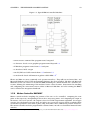
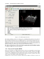
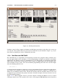
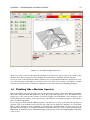
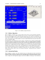
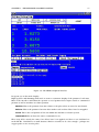


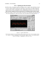

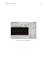


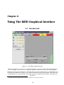
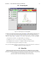


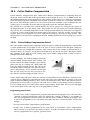


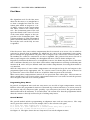
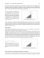

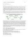


![[U4.82.03] Opérateur CALC_G](http://vs1.manualzilla.com/store/data/006360605_1-366f7ca4dad09cf95f3d589f4c996d79-150x150.png)