1
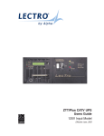
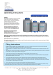
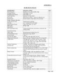
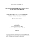
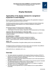
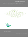
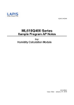
S TAT E B O U R N E
cryogenics
18 Parsons Road,
S TAT E B O U R N E
Parsons
Estate,
c r y o g Industrial
enics
Washington, Tyne and Wear
NE37 1EZ
S TAT E B O U R N E
cryogenics
S TAT E B O U R N E
cryogenics
Operating instructions
CRYOSTOR SERIES USER MANUAL
Models
CRYOSTOR 30
CRYOSTOR 60
CRYOSTOR 90
CRYOSTOR 120
CRYOSTOR 180
CRYOSTOR 240
www.statebourne.com
Tel: +44 (0) 191 416 4104
1
Fax: +44 (0) 191 415 0369
Email: [email protected]
User Manual
Contents
SECTION. CONTENTS.PAGE.
1.
Introduction.
3.
2.
Safety.
4.
3.
Commissioning
7.
4.
Operating.
9.
5.
Routine Maintenance & Siting
15.
6.
Replacement Parts.
16.
7.
Troubleshooting.
18.
8.
Schematic Diagrams.
19.
9.
Warranty.
22.
10.
Revision Log.
23.
11.
CE Declaration Of Conformity
22.
12.
Written Sceme Of Examination
25.
PLEASE READ THIS MANUAL CAREFULLY BEFOR OPERATION.
Check that the filling/delivery adaptors on the Cryostor correspond with those of the delivery tank hoses.
Ensure that all components used for filling or dispensing from the Cryostor are rated for the test pressure and
temperature extremes of the donor or receiver system.
The Cryostor can be filled by pump transfer, by overpressure from medium storage tanks or by gravity from low
pressure storage tanks.
The Trycock is set at 95% of the gross vessel volume.
WARNING: Overfilling of cryogenic vessels is hazardous and could lead to uncontrolled blowing of liquid.
The reason for this is that when the pressure rises, the boiling point also rises, the liquid warms up and expands
significantly.
The Cryostor is designed to be suitable for liquid nitrogen and argon only. The manufacturer does not accept any
responsibility where an unapproved media has been used.
The user is responsible for change in service procedures.
The vessel, pipework and relief system has been designed so that overpressurisation
cannot occur during or as a result of overfilling; however, the vessel should only be filled to trycock level and
never beyond.
Tel: +44 (0) 191 416 4104
2
Fax: +44 (0) 191 415 0369
Email: [email protected]
Section 1. Introduction
General.
The Cryostor Series is a range of stainless steel self pressurizing dewars for the storage of liquefied gases at
Cryogenic temperatures and at low pressures up to 3 Bar.
Whilst the gas is stored as a refrigerated liquid, both gas and liquid dispensing functions can be performed by this
unit to suit a wide range of applications.
Design & Construction.
Design Criteria.
The Cryostor Series are all designed and built to pressure vessel standard PD5500 and CE marked in accordance
with the Pressure Equipment Regulations 1999 No.2001.
Each vessel comprises of an austenitic stainless steel inner tank enclosed in a larger outer tank of similar material.
The isolation system between the two vessels consists of high vacuum and multi-layer high reflectivity
super-insulation.
The materials utilized are compatible with liquid nitrogen and argon.
The inner vessel is supported by its own neck tube at the top and a low loss location support at the bottom.
Vacuum Space Pressure Relief.
The interspace pressure relief function is carried out by the evacuation port, which is a 25mm stainless steel plug
held in place by the atmospheric pressure acting upon the outer shell, and it will simply fall out to relieve pressure
built up in the vacuum space in the event of a catastrophic failure, i.e. the inner vessel fracturing when full.
Safety Devices.
Pressure relief of the inner vessel is by dual safety devices. A spring-loaded pressure relief valve exists as the
primary protection this can be factory set at up to 3 BarG although 1.5 BarG is more usual.
Pressure build-up is released from the vessel as it exceeds the load exerted by the spring in its aperture, as the
pressure drops to below the spring’s rating the aperture closes. The secondary safety device is the “one-shot ”
burst disc, this is a fine nickel disc which has been designed to rupture at 4 BarG in the event of primary relief valve
failure. Once the disc has ruptured the vessel will no longer pressurize until a new unit is fitted.
Both primary and secondary devices on standard 1.5 Bar and 3 Bar units have threaded outlets to allow them to be
“piped away” when the dewar is being used in a confined space.
Other Features.
In addition to above safety devices the Cryostor series also have a pressure gauge, pressure regulator and an
electronic contents indicator, further explanation of the operation of these items is contained in section 4.
All Cryostors 30 up to the 240 are fitted with castors.
Tel: +44 (0) 191 416 4104
3
Fax: +44 (0) 191 415 0369
Email: [email protected]
Section 2. Safety
Introduction.
In all cryogen handling the following appropriate safety guidelines are essential if damage to equipment and personal
injury are to be avoided. The following guidelines provide a basic level of instruction in the precautions necessary but
are by no means exhaustive, a comprehensive approach involving staff training on a recognized course is strongly
recommended.
Liquefied Gases.
The potential hazards associated with liquefied gases are as follows:They are extremely cold and can cause severe burns, any injury of this nature should be treated as frostbite.
Liquid expands when vapourized into a gaseous state by a factor of between 538 ( CO2 ) and 842
( LO2 ) times. This means that a vapourizing liquid can cause a significant danger in an enclosed space.
Fire risk from aids to combustion such as oxygen enrichment.
Liquid Nitrogen.
The boiling point of liquid nitrogen is -196°C, 77K.
The molecular weight of nitrogen is 28.
Nitrogen gas is inert, odourless, tasteless and colourless.
Nitrogen gas is an asphyxiant.
Nitrogen liquid is odourless, colourless, slightly lighter than water and does not produce toxic or irritating vapours.
Liquid Argon.
The boiling point of liquid argon is -186°C, 87K.
The molecular weight of argon is 40.
Argon gas is extremely inert, odourless, tasteless and colourless.
Argon gas is an asphyxiant.
Argon liquid is odourless, colourless, and significantly heavier than water.
Other Liquids.
As the Cryostor series are designed for use with the two liquids described above under no circumstances should
storage of liquid oxygen, helium, carbon dioxide, or nitrous oxide be attempted as personal injury and damage to
equipment may result.
Ventilation.
Oxygen Depletion.
For a variety of reasons liquid gases should always be stored and used in well ventilated areas. In the case of
nitrogen, argon and carbon dioxide the major risks are from asphyxiation and the extreme cold generated by the
liquid and vapour. In a confined space suffocation can occur rapidly as the oxygen is displaced, a drop of only 2% in
the oxygen content is enough to pose a significant risk. In confined areas always use breathing apparatus or carry an
oxygen deficiency monitor.
Condensed Air.
Due to extreme cold air on the outside of transfer tubes and dewars can condense and form liquid air. Adequate
ventilation should ensure that any risk from this occurring is minimized, however, a strict no smoking or naked flame
rule must be observed.
Fire Precautions.
Do not smoke or permit open flames in any area where liquid gases are stored or used.
Ensure that prominent signs are displayed at all times to ensure this.
Safety Signs available from Statebourne go to:
www.statebourne.com
enter part number 3800150 in the search box
Tel: +44 (0) 191 416 4104
4
Fax: +44 (0) 191 415 0369
Email: [email protected]
Section 2. Safety
First Aid.
Asphyxiation.
Loss of consciousness or dizziness while working with liquid gases are obvious signs of asphyxiation due to an
oxygen deprived atmosphere. At the first signs of this the subject should be moved as quickly as possible from the
affected area. If breathing has stopped apply artificial respiration and summon medical assistance immediately.
Cryogenic Burns.
Cryogenic burns have a similar effect on the skin to frostbite. Similar method should be used in the treatment
of both.
Re-warm the affected area as quickly as possible in WARM water at about 40°C or by warm air.
Maintain general body warmth.
Do not rub or massage the affected area as this may cause more serious damage than already exists.
Seek medical advice as soon as possible.
Protective Equipment.
Cryogloves.
The wearing of a suitable pair of gloves is essential for day to day operations with liquefied gases.
Gloves generally fall into two categories. Those for handling objects in cold gas vapours are usually gauntlets of
mid-arm or shoulder length. For handling liquid dispensing hoses and dewars heavy duty leather wrist length gloves
can be used. Both are stocked by Statebourne.
part number 9701113 small
part number 9701115 medium
part number 9701117 large
part number 9701119 xtra large
part number 8701031
Aprons.
Face Shields and Hearing Protection.
Thermal aprons can also be worn to protect against
liquid splashes.
Clear visors are available to protect eyes and face from
liquid splashes.
part number 9701110 small
part number 8701032
part number 9701111 medium
part number 9701112 large
part number 8701007
Tel: +44 (0) 191 416 4104
5
Fax: +44 (0) 191 415 0369
Email: [email protected]
Section 2. Safety
Footwear.
Appropriate safety footwear should be worn at all times. Lightweight footwear and open sandals are not
recommended for obvious reasons. Wellington or loose fitting boots should be tied at the top to ensure that no
liquid can enter. As best protection use only approved safety footwear.
Oxygen Deficiency Monitors.
part number 9702141
part number 9702256
Analysis of the oxygen content in an atmosphere is often overlooked but can be one of the most fundamental safety
measures. A monitor can provide a constant analysis and thus increase safety.
Safety Posters:
part number 3800150
Statebourne’s Customer Service Department will be pleased to help with any queries you might have about safety
equipment. Our advice is FREE.
You may contact us via e mail at: [email protected]
Via the website using the contact us page: www.statebourne.com
Via the website using LIVE CHAT: www.statebourne.com
Customer services +44 (0) 191 416 4104
Tel: +44 (0) 191 416 4104
6
Fax: +44 (0) 191 415 0369
Email: [email protected]
Section 3. Commissioning
Preliminary Inspection.
On receipt of the tank it is worthwhile carrying out some basic checks to ensure that no damage has occurred
during transit and that the unit is in operational condition.
Remove all packaging carefully after first examining its condition, check all external surfaces for damage; dents,
scratches and marks should be noted and Statebourne advised immediately. If there is any doubt as to whether the
container has been damaged then any paperwork from the transporter should have this noted. Never use a
container with apparent physical damage.
Adaptors.
Check if the adaptors on the vessel inlet/outlet connections are compatible for the product to be carried as well as
for the customer’s operation.
Hoses.
Check that hoses are clean, free of moisture contamination and without damage.
Pressure Head Inspection.
Remove the red threaded valve protectors from each outlet valve. Check all valves for correct operation.
All handwheels should move smoothly and all fittings should be securely attached.
If there is any doubt consult Statebourne. Check the pressure gauge for damage, a cracked sight-glass or loose
casing can be dangerous. Check that in an unpressurized condition the pressure gauge reads zero.
Pressure
gauge
Valves
Content
Indicator &
Pressure
Raising Regulator
Valve Protectors
Please consult Statebourne if you have any doubts on the condition of your Cryostor.
Handling and Movement.
Care should always be taken when moving cryogenic equipment.
Failure to observe safe procedures may result in personal injury.
Extreme care should be taken when moving Cryostor units over uneven surfaces, operators should ensure that the
units are always under control and are stable.
If in doubt consult Statebourne Cryogenics or your Safety Officer.
Tel: +44 (0) 191 416 4104
7
Fax: +44 (0) 191 415 0369
Email: [email protected]
Section 3. Commissioning
Controlled Pressure Relief.
Even an extremely well insulated cryo tank will have heat transfer paths into the liquid, and the pressure
will slowly increase. Normally the Cryostor will have a max. working pressure of 3 barG.
Depending on the intended use or national regulations of the country of operation, a lower working
pressure may be required and the relief devices de-rated to suit.
From the top of the inner vessel there are pipe circuits through which gas can be vented.
Two different alternatives are available:
Open TRYCOCK VENT and relieve pressure to the atmosphere.
Trycock Valve
Relief Valve
Should the pressure in the vessel reach the desired MAWP then the safety relief valve will open and
remain open until a controlled pressure has been achieved. A bursting disc is also fitted as a secondary
back-up device.
The capacity of these safety devices are large enough to handle additional generated gases as a result
of loss of vacuum plus fire engulfment.
In an extreme case, should leakage occur on the inner vessel, then the combined vacuum pump down
and outer jacket relief port (shown below) will relieve the interspace overpressure by
dropping out when the pressure reaches 2 to 3 PSIG.
Vacuum pump down/outer jacket relief port
Tel: +44 (0) 191 416 4104
8
Fax: +44 (0) 191 415 0369
Email: [email protected]
Section 4. Operating.
Filling.
With all initial checks completed satisfactorily, the dewar may now be filled.
The operational valve sequence label on the side of the vessel describes the required
valve settings.
1.
Ensure that all valves are CLOSED.
2.
Open the TRYCOCK / VENT valve.
3. Connect the decant hose on the supply dewar to one of the two LIQUID FILL / DECANT
valves on the Cryostor. Ensure an in-line relief valve is connected to one end, between hose end and valve to relieve possible trapped gas in the line between two closed valves.
4. Open the selected LIQUID FILL / DECANT valve on the Cryostor to be filled.
5. Open the liquid supply valve on the supply dewar, liquid transfer should now begin.
The supply dewar pressure must be kept above the receiving dewar pressure to ensure reverse flow does
not occur.
Tel: +44 (0) 191 416 4104
9
Fax: +44 (0) 191 415 0369
Email: [email protected]
Section 4. Operating.
6.
The vapour being displaced through the TRYCOCK / VENT valve will eventually change to a stream of liquid as the Cryostor becomes full.
After this stream becomes constant close the liquid delivery valve on the supply dewar.
Close the LIQUID FILL / DECANT valve on the Cryostor dewar, and close the
TRYCOCK / VENT valve.
Trycock Valve
Relief Valve and Burst Disk
7.
Care must be taken when disconnecting the hose, as pressure may still be present.
8.
The Cryostor may now be pressurized or its contents stored at atmospheric pressure
for later use.
8.
WARNING: Never leave a dewar unattended while filling
NOTES.
Tel: +44 (0) 191 416 4104
10
Fax: +44 (0) 191 415 0369
Email: [email protected]
Section 4. Operating.
Pressure Building.
The Cryostor series have an integral pressure building vapourizer. To withdraw liquid or gas the dewar must first be
pressurized, the procedure for this is as follows.
1.
Ensure that ALL VALVES are closed.
2.
Open the PRESSURE BUILD valve.
The pressure regulator is factory set at 15 PSIG ( 1 BarG ) but may be adjusted to suit user requirements
between 2 PSIG and 20 PSIG, ( 0.1 BarG and 1.4 BarG ).
Regulator adjustments can be made as follows:Adjusting screw
Hexagon locking nut
a). Close PRESSURE BUILD valve, and loosen hexagon locking nut below adjusting screw.
b). Rotate adjusting screw anticlockwise to set to zero.
c). Close TRYCOCK/VENT valve and LIQUID FILL/DECANT valves, and open PRESSURE BUILD valve.
d). Rotate adjusting screw clockwise to increase vessel pressure. Adjust slowly and allow time for pressure
building gas to build up through pressure building vapourizer. Rotate adjusting screw anticlockwise until
desired pressure level is indicated on pressure gauge.
e). The pressure is now set – tighten locknut, to prevent rotation and tampering.
f).
The design of the regulator ensures that when the set pressure is reached the pressure building vapourizer
coil is shut down.
g). Vessels manufactured after Jan.1999 incorporate a self-relieving regulator, which will vent an
excess of gas generated from natural boil-off through a side vent hole when the vessel has not
been used for a few hours.
h). Vessels manufactured before Jan.1999 incorporate a non-relieving regulator, therefore when the
dewar is not being used for periods of longer than 24 hours it’s contents should be stored at
atmospheric pressure
(with the TRYCOCK / VENT valve open and the PRESSURE BUILD valve closed).
3.
WARNING: Never set the regulator pressure above the relief valve setting as excessive boil-off and
wear to the relief valve may occur.
Tel: +44 (0) 191 416 4104
11
Fax: +44 (0) 191 415 0369
Email: [email protected]
Section 4. Operating.
Liquid Withdrawal.
1.
Connect a suitable flexible transfer hose to one or both of the LIQUID FILL / DECANT valves from
which the liquid is to be dispensed.
The outlet fitting on a Cryostor is a
1/2" BSPP Female fitting.
the hose will need to have a
1/2" BSPTM (male) fitting.
2.
Ensure that the pressure within the dewar is sufficient to allow transfer to occur. A pressure of
10 PSIG ( 0.7 BarG ) is enough for most operations.
The Cryostor pressure must be kept above the process pressure to ensure reverse flow does not occur.
3.
Open the relevant LIQUID FILL / DECANT valve, liquid transfer should now occur.
4.
WARNING: Never leave a dewar unattended while transferring liquid.
Gas Withdrawal.
1.
Connect a suitable flexible transfer hose to the TRYCOCK / VENT valve.
2.
Open the PRESSURE BUILD valve. The Cryostor pressure must be kept above the process pressure to ensure reverse flow does not occur.
3
Open the TRYCOCK / VENT valve to begin gas delivery.
The outlet fitting on a Cryostor is a
1/2" BSPP Female.
the hose will need to have a
1/2" BSPT Male fitting.
Adapters.
If the Cryostor is to be disconnected or to be moved it may be better to fit an
adapter so that the female end of the hose together with swivel nut can be
conected. this will make removing the hose a lot easier.
The Adapter has a recessed cone connection so can link to hoses without the
need for Teflon tape. ( see picture)
Part No.1401335
1/2" BSPT MALE TO
1/2" BSPPM ADAPTER.
Part Number 1401335 1/2" BSPT MALE TO 1/2" BSPPM ADAPTER.
Connection to American products.
Connection hoses from american manufactured products are
usually a female CGA 295 fitting.
To connect the Cryostor to such a product you will need a
BSPM1/2" to CGA295 Male connector Part No.1201382
fitted to the fill/decant valve of the Cryostor.
Alternatively you can also use a statebourne hose which is a
1/2" BSPM to CGA295F 2 metre flexible hose Part No.3701106
for connecting the Cryostor directly to the American product.
3/4" fittings can be required for larger hoses.
Tel: +44 (0) 191 416 4104
12
Part Number 1201382
BSPM 1/2" to CGA295
Male connector.
Fax: +44 (0) 191 415 0369
Part Number 1201239
3/4 Male fitting.
(Adapter 1/2" to 3/4")
Email: [email protected]
Section 4. Operating.
LIQUID NITROGEN LEVEL INDICATOR WITH ANALOGUE DISPLAY. PART NUMBER (9702167)
DESCRIPTION AND OPERATION.
The Statebourne Level Indicator is a battery powered device housed in a tough ABS plastic case
with a clear polycarbonate front panel sealed to IP65.
Level indication is displayed by an analogue meter housed within the sealed case yet easily viewed through
the clear front panel.
A sealed “push to read” switch on the front panel activates the indicator when pressed to give a level reading.
A red LED positioned over the meter scale lights to show that the battery condition is OK.
A measurement probe permanently attached to the underside of the unit senses the depth of liquid nitrogen in
which it has been immersed. A simple calibration procedure sets the low and high points to represent a zero and
100 per cent measurement on the meter scale (see calibration). The length of the probe is chosen to suit the
particular vessel in which it is intended to be used.
SPECIFICATION.
INPUTS:
Power: 1 x PP3 Style Battery MN1604 or similar.
Sensor:
7.93mm OD Stainless Steel Coaxial Capacitor.
Length chosen to suit vessel ½” BSPT Male Fixing.
Calibration:
Two point calibration (see fig 2)
Adjustment RV1 – Zero Preset
Adjustment RV2 – Span Preset
OUTPUTS
Level Display: 50mm moving coil analogue meter scaled 0 – 100 to represent a percentage of the full and empty calibrated points. Accuracy
±10%
LED:
Lights when unit is activated.
Lights to show battery condition is OK.
PHYSICAL DIMENSIONS
Height
82mm
Width
80mm
Depth
55mm
Weight
0.25Kg without probe 0.75Kg with Cryostor 240 Probe
Tel: +44 (0) 191 416 4104
13
Fax: +44 (0) 191 415 0369
Email: [email protected]
Section 4. Operating.
CALIBRATION
1. Release the four panel screws and pull the front panel assembly away from the rear casing just enough to gain access to the two pre-sets .
two pre-sets
fig 2.
four panel screws
RV2-Span
2. Using a small trimtool or screwdriver locate the adjustment
pre-set RV2-Span and rotate at least ten times in an anticlockwise direction.
3. Press the push switch on the front panel and rotate the adjustment pre-set
RV1-Zero until the meter needle reads zero (0%).
4.
With the indicator and probe fitted to an empty vessel.
Fill the vessel to trycock level and allow time for the vessel to chill. Top up to trycock level again.
With the indicator and probe not fitted to vessel.
Immerse the probe in liquid nitrogen to desired full level and allow the probe to cool for at least five minutes.
5. Press the push switch on the front panel and rotate the adjustment pre-set RV2-Span until the meter reads full
(100%)
6. Replace the front panel assembly being careful not to trap the wires. Re-fasten the four panel screws.
POINTS TO NOTE
a). It will be necessary to change the battery if the battery condition LED fails to light when the push switch is pressed. The battery is housed behind the clear front panel which can be removed by releasing
the four corner screws (see fig.2) above. The battery can now be removed from it’s seat and replaced with one of similar type. Care should be taken when replacing the front panel that the cable harness lies
correctly, and does not foul any internal parts.
b). In the circumstances of the indicator/probe assembly being used in certain R.F. fields, the accuracy may be less than stated.
FOR SAFETY REASONS
a). DO NOT ATTEMPT TO DISMANTLE THE PROBE ASSEMBLY FITTINGS AT ANY TIME.
b). DO NOT ATTEMPT TO REMOVE THE LEVEL INDICATOR CASE FROM THE PROBE ASSEMBLY, AS THE INTERNAL WIRING MAY BE DAMAGED.
c). WHEN FITTING THE PROBE ASSEMBLY TO THE VESSEL MANIFOLD TIGHTEN ONLY BY THE PART INDICATED IN FIG.1.
Tel: +44 (0) 191 416 4104
14
Fax: +44 (0) 191 415 0369
Email: [email protected]
Section 5. Routine Maintenance and Siting.
SECTION 5 – ROUTINE MAINTENANCE & SITING
External.
By simple periodic care and maintenance the service life of your Cryostor can be extended.
All external surfaces should be kept clean and free from oil and grease.
Servicing should only be carried out by competent personnel.
Check relief valves for satisfactory operation annually and replace if necessary.
Only fit parts compatible with the dewar ( if in doubt consult Statebourne ).
In the United Kingdom the Cryostor series should be inspected to a schedule compatible with the
PRESSURE SYSTEMS SAFETY REGULATIONS 2000 No.128. Failure to comply with the regulations’ requirements
may mean that operating with the dewar is illegal. If in doubt consult Statebourne.
In other countries the Government Health and Safety Authority should be consulted.
PERIODIC INSPECTION & MAINTENANCE
Introduction
In order to ensure the continued safe operation of your Cryostor it is necessary to carry out regular planned period
inspection and preventative maintenance.
The periodic inspection and maintenance regime should, where required meet any local regulations and as an absolute minimum include the following:
•
•
•
Visual inspection of tank, all external components and lines.
Leak testing at the MAWP or main relief valve limit.
Functional testing of valves, relief devices and contents indicator.
The suggested frequency for the above tests depends upon local conditions. As a minimum the intervals between
tests should not exceed three years. The suggested testing scope is as follows:
Periodic Checks (To be performed at between 1 and 3 yearly intervals).
•
•
•
•
•
•
Visual inspection of tank, all external components and lines. Check the dataplate is attached and check the tank is operating within design limits.
Check correct specification relief valve is fitted. Check exhaust ports are free from obstructions.
Lift and reseat testing of relief valve to confirm correct operation.
Check pressure gauge condition and verify accuracy against calibrated unit.
Leak testing of all assembled joints at Primary RV pressure setting.
Check correct function of pressure regulator
Replace contents indicator battery where applicable, check calibration and adjust where necessary.
Records
A qualified or competent person should only carry out all inspection and maintenance operations on the Cryostor
Series.
All operations should follow a written scheme of examination and be noted with all recorded details maintained for
future reference and review.
Users should consult their own particular Health & Safety Regulations to ensure full compliance with local requirements.
User Note
It is the responsibility of the person maintaining the Cryostor that all components used are safe and suitable for the
intended application. If in doubt consult Statebourne’s Technical Department.
SITING
For siting of the Cryostor indoors, the building must be of non-combustible construction, be adequately vented,
and ideally be used exclusively for gas storage. All relief devices should be vented externally. As per above the vessel should not be beneath or exposed by the failure of electrical power lines, flammable or combustible liquid lines,
or flammable gas lines.
You may contact us via e mail at: [email protected]
Via the website using the contact us page: www.statebourne.com
Via the website using LIVE CHAT: www.statebourne.com
Customer services +44 (0) 191 416 4104
Tel: +44 (0) 191 416 4104
15
Fax: +44 (0) 191 415 0369
Email: [email protected]
Section 6. Replacement Parts.
Cryostor 120.
Part No.Description.Inlet.Outlet.No. per vessel.
1901053
Burst disc assembly, 4 Bar.
1/4”NPTM
1/4”NPTF
1
1801102
Relief valve, 1.5 Bar ( 22 PSI )
1/4”NPTM
3/8”NPTF
1*
1801275
Relief valve, 3 Bar 1/4”NPTM
3/8”NPTF
1*
1801255
Relief valve, 1.5 Bar
1/4”NPTM
3/8”BSPPF
1 (BOC ONLY)
2001091
Pressure gauge, 0-60PSI, 63mm.
1/4”NPTM
N/A.
1
2101105
Pressure regulator, 1-50 PSI, set at 15 PSI.
1/4”BSPTF
1/4”BSPTF
1
1701085
Valve repair kit.
N/A.
N/A.
N/A.
2201013
Evacuation port blow out cover.
N/A.
N/A.
1
3101101
4” Swivel castor with brake.
N/A.
N/A.
4
3803001
Operational valve sequence label.
N/A.
N/A.
1
3801071
Trycock vent label.
N/A.
N/A.
1
3801073
Liquid fill / decant label.
N/A.
N/A.
2
3801074
Relief valve label.
N/A.
N/A.
1
3801075
Burst disc label.
N/A.
N/A.
1
3801076
Pressure build label.
N/A.
N/A.
1
9702020
Contents Indicator with Probe
N/A
N/A
1
Cryostor 180.
Part No.Description.Inlet.Outlet.No. per vessel.
1901053
Burst disc assembly, 4 Bar.
1/4”NPTM
1/4”NPTF
1
1801102
Relief valve, 1.5 Bar ( 22 PSI )
1/4”NPTM
3/8”NPTF
1*
1801275
Relief valve, 3 Bar 1/4”NPTM
3/8”NPTF
1*
1801255
Relief valve, 1.5 Bar
1/4”NPTM
3/8”BSPPF
1 (BOC ONLY)
2001091
Pressure gauge, 0-60PSI, 63mm.
1/4”NPTM
N/A.
1
2101105
Pressure regulator, 1-50 PSI, set at 15 PSI.
1/4”BSPTF
1/4”BSPTF
1
1701085Valve repair kit.N/A.N/A.N/A.
2201013
Evacuation port blow out cover.
N/A.
N/A.
1
31011024” Fixed castor.N/A.N/A.2
31011014” Swivel castor with brake.N/A.N/A.2
3803001Operational valve sequence label.N/A.N/A.1
3801071Trycock vent label.N/A.N/A.1
3801073Liquid fill / decant label.N/A.N/A.2
3801074Relief valve label.N/A.N/A.1
3801075Burst disc label.N/A.N/A.1
3801076Pressure build label.N/A.N/A.1
9702021Contents Indicator with ProbeN/AN/A1
Cryostor 240.
Part No.Description.Inlet.Outlet.No. per vessel.
1901053
Burst disc assembly, 4 Bar.
1/4”NPTM
1/4”NPTF
1
1801102
Relief valve, 1.5 Bar ( 22 PSI )
1/4”NPTM
3/8”NPTF
1*
1801275
Relief valve, 3 Bar 1/4”NPTM
3/8”NPTF
1*
1801255
Relief valve, 1.5 Bar
1/4”NPTM
3/8”BSPPF
1 (BOC ONLY)
2001091
Pressure gauge, 0-60PSI, 63mm.
1/4”NPTM
N/A.
1
2101105
Pressure regulator, 1-50 PSI, set at 15 PSI.
1/4”BSPTF
1/4”BSPTF
1
1701085Valve repair kit.N/A.N/A.N/A.
2201013
Evacuation port blow out cover.
N/A.
N/A.
1
31011024” Fixed castor.N/A.N/A.2
31011014” Swivel castor with brake.N/A.N/A.2
3803001Operational valve sequence label.N/A.N/A.1
3801071Trycock vent label.N/A.N/A.1
3801073Liquid fill / decant label.N/A.N/A.2
3801074Relief valve label.N/A.N/A.1
3801075Burst disc label.N/A.N/A.1
3801076Pressure build label.N/A.N/A.1
9702022
Contents Indicator with Probe
N/A
N/A
1
* 1.5 Bar or 3 Bar relief valves are fitted, not both.
Tel: +44 (0) 191 416 4104
16
Fax: +44 (0) 191 415 0369
Email: [email protected]
Section 6. Replacement Parts.
SECTION 6 – REPLACEMENT PARTS
Cryostor 30.
Part No.Description.Inlet.Outlet.No. per vessel.
1901053
Burst disc assembly, 4 Bar.
1/4”NPTM
1/4”NPTF
1
1801102
Relief valve, 1.5 Bar ( 22 PSI )
1/4”NPTM
3/8”NPTF
1*
1801275
Relief valve, 3 Bar 1/4”NPTM
3/8”NPTF
1*
1801255
Relief valve, 1.5 Bar
1/4”NPTM
3/8”BSPPF
1 (BOC ONLY)
2001091
Pressure gauge, 0-60PSI, 63mm.
1/4”NPTM
N/A.
1
2101105
Pressure regulator, 1-50 PSI, set at 15 PSI.
1/4”BSPTF
1/4”BSPTF
1
1701085Valve repair kit.N/A.N/A.N/A.
2201013
Evacuation port blow out cover.
N/A.
N/A.
1
31011003” Swivel castor.N/A.N/A.4
3803001Operational valve sequence label.N/A.N/A.1
3801071Trycock vent label.N/A.N/A.1
3801073Liquid fill / decant label.N/A.N/A.2
3801074Relief valve label.N/A.N/A.1
3801075Burst disc label.N/A.N/A.1
3801076Pressure build label.N/A.N/A.1
9702017Contents Indicator with ProbeN/AN/A1
Cryostor 60.
Part No.Description.Inlet.Outlet.No. per vessel.
1901053
Burst disc assembly, 4 Bar.
1/4”NPTM
1/4”NPTF
1
1801102
Relief valve, 1.5 Bar ( 22 PSI )
1/4”NPTM
3/8”NPTF
1*
1801275
Relief valve, 3 Bar 1/4”NPTM
3/8”NPTF
1*
1801255
Relief valve, 1.5 Bar
1/4”NPTM
3/8”BSPPF
1 (BOC ONLY)
2001091
Pressure gauge, 0-60PSI, 63mm.
1/4”NPTM
N/A.
1
2101105
Pressure regulator, 1-50 PSI, set at 15 PSI.
1/4”BSPTF
1/4”BSPTF
1
1701085Valve repair kit.N/A.N/A.N/A.
2201013
Evacuation port blow out cover.
N/A.
N/A.
1
31011003” Swivel castor.N/A.N/A.4
3803001Operational valve sequence label.N/A.N/A.1
3801071Trycock vent label.N/A.N/A.1
3801073Liquid fill / decant label.N/A.N/A.2
3801074Relief valve label.N/A.N/A.1
3801075Burst disc label.N/A.N/A.1
3801076Pressure build label.N/A.N/A.1
9702018Contents Indicator with ProbeN/AN/A1
Cryostor 90.
Part No.Description.Inlet.Outlet.No. per vessel.
1901053
Burst disc assembly, 4 Bar.
1/4”NPTM
1/4”NPTF
1
1801102
Relief valve, 1.5 Bar ( 22 PSI )
1/4”NPTM
3/8”NPTF
1*
1801275
Relief valve, 3 Bar 1/4”NPTM
3/8”NPTF
1*
1801255
Relief valve, 1.5 Bar
1/4”NPTM
3/8”BSPPF
1 (BOC ONLY)
2001091
Pressure gauge, 0-60PSI, 63mm.
1/4”NPTM
N/A.
1
2101105
Pressure regulator, 1-50 PSI, set at 15 PSI.
1/4”BSPTF
1/4”BSPTF
1
1701085Valve repair kit.N/A.N/A.N/A.
2201013
Evacuation port blow out cover.
N/A.
N/A.
1
31011003” Swivel castor.N/A.N/A.4
3803001Operational valve sequence label.N/A.N/A.1
3801071Trycock vent label.N/A.N/A.1
3801073Liquid fill / decant label.N/A.N/A.2
3801074Relief valve label.N/A.N/A.1
3801075Burst disc label.N/A.N/A.1
3801076
Pressure build label.
N/A.
N/A.
1
9702019Contents Indicator with Probe N/AN/A1
Tel: +44 (0) 191 416 4104
17
Fax: +44 (0) 191 415 0369
Email: [email protected]
Section 7. Trouble shooting
PROBLEM
Vessel builds excessive pressure
or builds pressure too fast.
POSSIBLE CAUSE
CORRECTIVE ACTION
Vessel has been over-filled.
If the vessel is filled past the vent trycock, the
pressure may rise rapidly after a fill.
Pressure build regulator has been set improperly, or
unit is leaking.
If the pressure builds and stays at a level
higher than desired, adjust the regulator to
a new setting (see section 4.)
If the pressure builds to the relief valve setting and
the pressure build coil near the bottom of
the tank is cold or frosted, replace the regulator.
Vacuum is deteriorating.
This can be observed by cold or frost being evenly
distributed over the outer jacket surface. Refer to
the troubleshooting section on frost.
Pressure Build valve is open.
Close the valve.
Pressure build regulator is set too low.
Adjust regulator as section 4.
Pressure build regulator is not operating properly.
Remove and bench test regulator for pressure build
setting.
Vessel has a leak.
Check for frost on lines or on top of head. Listen
for hissing, soap test joints for leaks. Isolate leak
and call Statebourne for repair details.
Frost occurs around the circumference
of the outer jacket 25 to 150mm from the
bottom.
Vessel is building pressure with pressure build circuit.
This is normal if the vessel pressure is lower than
the regulator pressure build setting.
Frost occurs on head or knuckle.
Residual frost remains from last fill or recent product use.
This is normal. Ice may remain for days after a fill
or heavy use.
Frost occurs evenly over the outer jacket
surface.
Vessel has lost vacuum.
This is accompanied by high rate of pressure rise
or high loss rate.Call Statebourne for return
instructions.
Miscellaneous frost spots on vessels.
Vessel may have internal damage.
Call Statebourne for return or repair instructions.
In liquid delivery, liquid is mixed with
high amount of gas.
Vessel pressure is higher than optimum for liquid
withdrawal.
Reset the vessel pressure for liquid use. Also, use a
phase separator in the end of the transfer hose.
Frost is residual from last fill or earlier use.
This is normal a ring of ice often remains on the
vessel after last use or fill.
Flat or faulty battery.
Check and or replace battery.
Cryostor pressure is too low.
Content indicator not working.
Internal connection broken due to the indicator
being turned
The copper joint between the brass screw and the circuit
board should have no signs of damage, if this
has snapped a new content indicator will be required
(possibly a content indicator and full probe depending on
the damage).
Check that this screw is tight.
Tel: +44 (0) 191 416 4104
18
Fax: +44 (0) 191 415 0369
Email: [email protected]
Section 8. Schematic Diagrams
Dispensing Manifold.
9
4
2
5
1
7
8
6
3
Key.
1.
2.
3.
4.
5.
6.
7.
8.
9.
LIQUID FILL DECANT. = 1/2" BSPP Female fitting.
TRYCOCK VENT.
= 1/2" BSPP Female fitting.
LIQUID FILL DECANT. = 1/2" BSPP Female fitting.
PRESSURE BUILD.
PRESSURE REGULATOR.
PRESSURE GAUGE.
BURST DISC.
RELIEF VALVE.
EVACUATION PORT COVER.
4
9
2
5
7
1
6
8
Tel: +44 (0) 191 416 4104
19
3
Fax: +44 (0) 191 415 0369
Email: [email protected]
Section 8. Schematic Diagrams
P & ID DIAGRAM
Key.
1.
LIQUID FILL DECANT VALVE. = 1/2" BSPP Female fitting.
2.
TRYCOCK VENT VALVE.
= 1/2" BSPP Female fitting.
3.
LIQUID FILL DECANT VALVE. = 1/2" BSPP Female fitting.
4.
PRESSURE RAISE VALVE.
5.
PRESSURE REGULATOR.
6.
PRESSURE GAUGE.
7.
BURST DISC.
8.
RELIEF VALVE.
9.
PUMP DOWN PORT.
Tel: +44 (0) 191 416 4104
20
Fax: +44 (0) 191 415 0369
Email: [email protected]
Section 8. Schematic Diagrams
Content indicator. fiq 1.
LED INDICATOR
LEVEL DISPLAY
PUSH TO READ SWITCH
PANEL RELEASE SCREWS
LENGH TO SUIT VESSEL
TIGHTEN PROBE ASSEMBLY BY THIS PART ONLY
Tel: +44 (0) 191 416 4104
21
Fax: +44 (0) 191 415 0369
SENSOR PROBE
Email: [email protected]
Section 8. Schematic Diagrams
VIEW OF PRESETS WITH COVER REMOVED. fig 3.
RV1 - ZERO RESET
RV2 - SPAN RESET
BATTERY FITTED.
Tel: +44 (0) 191 416 4104
22
Fax: +44 (0) 191 415 0369
Email: [email protected]
Section 9 . Warranty.
SECTION 9 - WARRANTY
Product Warranty.
The Cryostor series of low pressure cryogenic dewars carry a vacuum warranty of 5 years from the date of
shipment to the original purchaser of the equipment.
Additionally the Cryostor series is warranted to be free from defects in materials and workmanship for a period of
90 days. Materials and component parts supplied or manufactured by other companies and sold by Statebourne
are warranted for the same period of 90 days but only if so warranted by the original manufacturers and suppliers.
This Product Warranty shall only become operable if the purchaser of the equipment settles all outstanding
amounts to Statebourne Cryogenics Ltd in accordance with its standard terms and conditions of sale.
Purchasers obligations under warranty.
1.
Inspect goods fully upon delivery.
2.
Give Statebourne written notice of any claim or defect within 7 days of the discovery of such defect.
3.
Return the said defective equipment freight prepaid to Statebourne Cryogenics.
4.
Use the equipment supplied in accordance with published operating instructions.
5.
To use only Statebourne approved accessories and spare or replacement parts with the equipment.
6.
Not to permit alteration or repairs by others unless explicitly authorised in writing by
Statebourne Cryogenics.
Failure to observe the above obligations will result in this product warranty being void.
Statebourne Cryogenics will not be liable for defects caused by normal wear and tear, erosion, corrosion, fire or
explosion.
Statebourne Cryogenics liability under this warranty will not exceed repair, replacement or at its option original
purchase price. Additionally, Statebourne will not be liable for any other losses, including consequential losses,
damages or delay.
There are no warranties or guarantees, either express or implied including any warranties of merchantability or
fitness for particular purpose other than those specifically expressed herein.
Tel: +44 (0) 191 416 4104
23
Fax: +44 (0) 191 415 0369
Email: [email protected]
Section 10. Revision log.
Issue No.
Section.
Revision Summary.
Authorized By.
1st Issue
2nd Issue
JCH
4
Filling and dispensing procedures amended suitable for twin fill decant model.
6
Parts amended to show twin fill decant design
Date.
1/96
7
Schematic diagrams amended to illustrate twin fill decant valve arrangement.
JCH
3/96
3rd Issue
3
Handling and Movement para. added.
CR
4/97
4th issue
1
Note regarding oxygen compatibility amended.
KH
1/98
5th
6
Cryostor 200 added to range.
CR
7/98
6th isuue
6
Burst disc was 3/8” NPTf out, now ¼” NPTf
CR
8/98
7th issue
4
Contents indicator instructions added.
KH
1/98
6
Part nos. added for replacement contents
8th issue
6
Part nos. on 3 Bar R.V. and pressure regulator updated.
CR
1/99
9th issue
4
Contents indicator calibration instructions updated.
KH
3/99
10th issue
6
Castor change to CS30/60/90
CR
4/00
Updated for PER 1999 regulations
CR
5/02
3/03
11th issue
12th issue
4
Regulator adjustment update
CR
13th issue
4
New instructions for mk.2 indicator 9702167
CR
6/03
14th issue
6
New part nos. for BOC spec only relief valves added
CR
11/04
15th issue
6
1801275 replaces 1801166
CR
12/06
16th issue
All
New pdf version created using Adobe CS5
TH/CR/AM
12/14
17th issue
5
Product and Part number changed
TH
05/15
18th issue
8
P & ID added to Schematic Diagrams
TH/KH
07/15
USEFUL CONTACT INFORMATION.
www.statebourne.com
E Mail us at [email protected]
Telephone us at +44 (0) 191 416 4104
Use LIve Chat by logging in at www.statebourne.com
Send a diect message by going to www.statebourne.com/contacts/contact-us
Tel: +44 (0) 191 416 4104
24
Fax: +44 (0) 191 415 0369
Email: [email protected]
V3.07-15 17th Issue
Section 11 . Pressure Equipment Directive.
Tel: +44 (0) 191 416 4104
25
Fax: +44 (0) 191 415 0369
Email: [email protected]
Written Scheme Of Examination
Reference No.:
Date of issue:
Revision:
Vessel Type:
Serial Number:
Part Number:
Owner/User:
Design code:
Name of Manufacturer:
Vessel service:
User’s ref/plant No:
Details of site and
application:
The above referenced pressure vessel shall be subject to periodic examination as specified by this scheme in
accordance with the SI 2000 No. 128 The Pressure Systems Safety Regulations 2000.
All examinations shall be carried out by a competent person as defined by the regulations and assigned by
Statebourne Cryogenics Ltd
User Responsibility
The user is responsible to ensure a written scheme is drawn up, modified where necessary and reviewed by
the competent person for continuing suitability for each vessel.
The user shall ensure examination is carried out as defined by the scheme
The user shall ensure the vessel is not operated after
• The date specified for any repair or modification to the safe working limits by the competent person
has elapsed.
• The date specified for next examination under the scheme has elapsed.
• The date for next examination is legibly and durably marked and the mark is clearly visible.
The user is responsible to provide any person operating the vessel with adequate instruction for safe
operation and action to be taken in case of any emergency.
The user shall ensure the vessel is properly maintained and in good repair so as to prevent danger.
Competent person Responsibility
The competent person shall specify the nature and frequency of the examination.
The competent person shall issue a written report to the user within 28 days of completion of examination.
The report shall state
• The parts examined, the condition of those parts and the results of the examinations
• Any repairs or changes to the safe operating limits required to prevent danger. The date by which repairs or modifications must be taken shall be specified.
• Specify the date after which the vessel may not be operated without further examination under the scheme.
• State whether the scheme is suitable for the purpose of preventing danger, and if not any modification required with reasons for the modifications also stated.
Scheme of examination
Yearly Checks
Visual inspection of tank, all external components and lines.
Check the dataplate is attached and check the tank is operating within design limits.
Check correct specification relief valve is fitted.
Check exhaust ports are free from obstructions.
Lift and reseat testing of relief valve to confirm correct operation.
Leak testing of all assembled joints at Primary RV pressure setting.
Check operation of contents indicator. Replace battery, check calibration and adjust where necessary.
Page 1.of 2.
Written Scheme Of Examination
Reference No.:
Date of issue:
Revision:
5 Yearly Checks
Check pressure gauge accuracy against calibrated unit.
Replace pressure regulator
Replace Relief Valve
Replace Burst disc
Action in case of imminent danger
Where in the opinion of the competent person there is imminent danger until repairs or modifications are
carried out, the written report shall be issued to the user directly with a copy sent within 14 days to the
enforcing authority for the premises at which the vessel situated.
The user shall ensure the vessel is not operated until the repairs or modifications have been carried out
Modification and repair
The employer of a person who modifies or repairs the vessel shall ensure the repair does not give rise to
danger or impair the operation of any protective device.
Keeping of records
The user shall keep the last report and any previous reports which will assist in assessing whether
• The vessel is safe to operate, or
• Any repairs can be carried out safely.
Records shall be kept
• For installed systems at the premises where the system is situated.
• For mobile vessels at the premises from which deployment is controlled.
Date:
Issue status:
Written by:
Approved by:__________________________________________
Competent person
for and on behalf of Statebourne Cryogenics Ltd
Accepted by:__________________________________________
Authorised representative
for and on behalf of user/owner
Page 2.of 2.