1
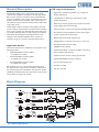
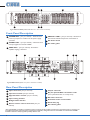
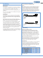
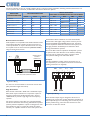
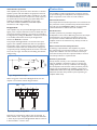
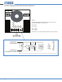
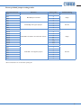
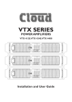
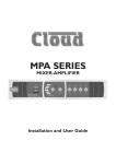
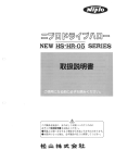
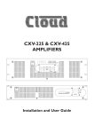
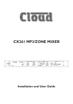
VTX SERIES POWER AMPLIFIERS VTX 4120,VTX 4240,VTX 4400 CHANNEL 1 2 3 4 PROTECT O PEAK SIGNAL I POWER VTX 4120 4x 120W Amplifier CHANNEL 1 2 3 4 PROTECT O PEAK SIGNAL I POWER VTX 4240 4x 240W Amplifier CHANNEL 1 2 3 4 PROTECT O PEAK SIGNAL I POWER VTX 4400 4x 400W Amplifier Installation and User Guide WARNING: To reduce the risk of fire or electric shock, do not expose this appliance to rain of moisture. CAUTION: Use of controls or adjustments or performance of prodedures other than those specified may result in hazardous radiation exposure. CAUTION RISK OF ELECTRIC SHOCK DO NOT OPEN WARNING: SHOCK HAZARD - DO NOT OPEN AVIS: RISQUE DE CHOC ÉLECTRIQUE - NE PAS OUVRIR The lightning flash with the arrowhead symbol within an equilateral triangle, is intended to alert you to the presence of uninsulated dangerous voltages within the product’s enclosure that may be of sufficient magnitude to constitute a risk of electric shock. The exclamation point within and equilateral triangle is intended to alert the user to the presence of important operating and maintenance (servicing) instructions in the literature accompanying the appliance. IMPORTANT SAFETY INSTRUCTIONS 1. Read these Instructions. 2. Keep these Instructions. 3. Heed all Warnings. 4. Follow all instructions. 5. Do not use this apparatus near water. 6. Clean only with a dry cloth. 7. Do not block any ventilation openings. Install in accordance with the manufacturer’s instructions. 8. Do not install near any heat sources such as radiators, heat registers, stoves, or other apparatus (including amplifiers) that produce heat. 9. Do not defeat the safety purpose of the polarized or grounding - type plug. A polarized plug has two blades with one wider than the other. A grounding type plug has two blades and a third grounding prong. The wide blade or the third prong are provided for your safety. When the provided plug does not fit into your outlet, consult an electrician for replacement of the obsolete outlet. 10. Protect the power cord from being walked on or pinched particularly at plugs, convenience receptacles, and the point where they exit from the apparatus. 11. Only use attachments/accessories specified by the manufacturer. 12. Use only with a cart, stand, tripod, bracket, or table specified by the manufacturer, or sold with the apparatus. When a cart is used, use caution when moving the cart/apparatus combination to avoid injury from tip-over. 13. Unplug this apparatus during lightning storms or when unused for long periods of time. 2 VTX Series User Manual v1.0 14. Refer all servicing to qualified service personnel. Servicing is required when the apparatus has been damaged in any way, such as power-supply cord or plug is damaged, liquid has been spilled or objects have fallen into the apparatus, the apparatus has been exposed to rain or moisture, does not operate normally, or has been dropped. Do not expose the apparatus to dripping or splashing, and ensure that no objects filled with liquids, such as vases, are placed on the apparatus. L’appareil ne doit pas être exposé aux écoulements ou aux éclaboussures et aucun objet ne contenant de liquide, tel qu’un vase, ne doit être placé sur l’objet. The mains plug is used as the disconnect device and it should remain readily accessible during intended use. In order to electrically isolate the apparatus from the mains, the mains plug should be completely removed from the mains outlet socket. La prise du secteur ne doit pas être obstruée ou doit être facilement accessible pendant son utilisation. Pour être complètement déconnecté de l’alimentation d’entrée, la prise doit être débranchée du secteur. This apparatus is of Class I construction and must only be connected to a mains outlet socket with a protective earthing connection. Terminals marked with the ( ) symbol may use Class 2 Wiring, but voltages at these terminals may be of sufficient magnitude to constitute a risk of electric shock. The external wiring connected to these terminals requires installation by an instructed person or the use of pre-made leads or cords. Contents Safety Information......................................... 4 Safety Notes regarding Installation......................... 4 Safety Considerations and Information................. 4 General Description....................................... 5 VTX range main features.......................................... 5 Applicable Models....................................................... 5 Block Diagram................................................ 5 Front Panel Description................................ 6 Rear Panel Description.................................. 6 Installation...................................................... 7 Mechanical.................................................................... 7 Ventilation..................................................................... 7 Connections and adjustments.................................. 7 Protection....................................................... 9 Bose® equalisation modules (optional)....................................................... 10 Installation..................................................................10 General Notes.............................................. 10 EMC Considerations................................................10 Earthing.......................................................................10 Appendix....................................................... 11 Technical Specifications...........................................11 General Specifications.............................................11 Location of jumpers and other internal components...............................................................12 Factory default jumper settings table...................13 3 VTX Series User Manual v1.0 Safety Information Caution - High Voltages Safety Notes regarding Installation Do not touch any part or terminal carrying the hazardous live symbol ( ) while power is supplied to the unit. •• Do not expose the unit to water or moisture. •• Do not expose the unit to naked flames. •• Do not block or restrict any air vent. •• Do not operate the unit in ambient temperatures above 35 C. O •• Do not touch any part or terminal carrying the hazardous live symbol ( the unit. ) while power is supplied to •• Do not perform any internal adjustments unless you are qualified to do so and fully understand the hazards associated with mains-operated equipment. •• The unit has no user-serviceable parts. Refer servicing to qualified service personnel. •• If the moulded plug is cut off the AC power lead for any reason, the discarded plug is a potential hazard and should be disposed of in a responsible manner. Conformities This product conforms to the following European EMC Standards: BS EN 55103-1:2009 BS EN 55103-2:2009 This product has been tested for use in commercial and light industrial environments. If the equipment is used in controlled EMC environments, the urban outdoors, heavy industrial environments or close to railways, transmitters, overhead power lines etc. the performance of the unit may be degraded. The product conforms to the following European electrical safety standard: Terminals to which the hazardous live symbol refers require installation by a qualified person. Caution - Mains Breaker VTX Series amplifiers are fitted with a resettable mains circuit breaker instead of a replaceable fuse. This is located on the rear panel above the AC mains input connector. The circuit breaker may be reset by pressing it in; however, its operation may indicate an internal fault. If the circuit breaker operates immediately the power is restored, no further attempt should be made to use the amplifier, and it should be returned to your Cloud service centre or other qualified person for repair. Caution - Servicing The unit contains no user serviceable parts. Refer servicing to qualified service personnel. Do not perform servicing unless you are qualified to do so. Only a qualified service technician should remove the top cover of the unit. Disconnect the power cable from the unit before removing the top panel and do not make any internal adjustments with the unit switched on. Service personnel - do not disconnect the rear panel Earth Safety tag until the unit has been completely isolated from the mains. On re-assembly, ensure that the connection to the Earth Safety tag is replaced before reconnecting the unit to the mains supply. If the unit requires repair, only fit replacement parts specified by the manufacturer, or parts with identical electrical characteristics. Substituting parts which are not authorized by the manufacturer may result in fire, electric shock or other safety hazards. Only reassemble the unit using bolts/screws identical to the original parts. BS EN 60065:2002 The VTX Series was developed and manufactured with high quality materials and components, which can be recycled and/or reused. What’s in the Box Safety Considerations and Information The packing carton should contain the following items: The unit must be earthed. Ensure that the mains power supply provides an effective earth connection using a threewire termination. • VTX amplifier • IEC mains lead • Set of mating screw-terminal connectors • Set of four push-in feet (for free-standing use) • This manual When the mains switch is in the off (‘O’) position the live and neutral conductors of the mains transformer are disconnected. 4 VTX Series User Manual v1.0 Please check the shipping carton for damage; if there is any, please contact your Cloud agent and the shippers. General Description Cloud VTX amplifiers are a range of high power multichannel audio amplifiers intended for use with high quality PA and music systems in locations where unquestionable long-term reliability is the primary consideration. As well as theatres, leisure centres and other major venues, they are also ideal for airport terminals, railways stations and similar large public spaces. VTX amplifiers deliver excellent audio quality at all rated powers and have all the facilities and features that installers have come to expect from Cloud products. The VTX range are the first Cloud products to offer a plug-in surveillance card option, permitting the operating parameters and settings of all networked amplifiers to be monitored anywhere, using any computer’s standard web browser. Applicable Models: This manual describes the installation and operation of the following models: • Cloud VTX4120 4-channel amplifier – 4 x 120 W into 4 ohms • loud VTX4240 4-channel amplifier C – 4 x 240 W into 4 ohms • loud VTX4400 4-channel amplifier C – 4 x 400 W into 4 ohms All models are 2U, 19” rack-mounting units. Apart from the output power rating, the three models are identical for the practical purposes of installation and operation. Unless specifically stated otherwise, the information in this manual may be taken to apply to all models. VTX range main features: • High power multichannel amplifiers for “install-andforget” applications • 120 W, 240 W or 400 W per channel into 4 ohms (model-dependent) • Extensive protection against short-circuit and reactive loads, clipping, DC and overheating • Chs1 & 2 and/or 3 & 4 may be operated in Bridge Mode • Per-channel, front-panel LEDs for power status, signal presence, peak level and protection • Balanced line level inputs with gain trim • Configurable for 4 channel, dual stereo or mono use • Per-channel switched hi-pass filter (18 dB/oct below 65 Hz) • Optional VTX-WM1 card allows amplifier monitoring from a standard web browser • Optional remote volume control (per-channel) • Optional Bose® EQ cards (per-channel) • 2U 19” rackmounting unit • Forced-air cooling • Five year warranty Block Diagram fig.1: VTX Series Block Diagram VTX Series User Manual v1.0 5 6 5 3 4 2 1 6 fig.2: VTX Front Panel (NOTE:VTX4120 shown – other models are identical) Front Panel Description 1 POWER LEDs - (one per channel) – illuminate after power-up sequence to confirm normal power supply operation 2 SIGNAL LEDs – (one per channel) – illuminate when the input signal level exceeds -26dBu 3 PEAK LEDs – (one per channel) - illuminate if amplifier clipping is detected 3 PROTECT LEDs – (one per channel) – illuminate if the internal heatsink temperature exceeds 90 °C 5 AC Power switch 6 Air intake grilles 12 6 5 CHANNEL 2 CHANNEL 3 SPEAKER OUTPUTS 4 OHMS - MIN ON BRIDGE 1-2 CH2 CH4 0V CH3 BRIDGE 3-4 CH4 OFF ON 0V OFF CH3 ON 0V OFF ON BRIDGE 3-4 CH2 OFF 10 CHANNEL 4 BRIDGE 1-2 0V CHANNEL 1 11 5 8 CH1 12 4 POWER ~ 40-60Hz 10% 4 2 4 4 7 1 9 fig.3: VTX Rear Panel (NOTE: rear panel is identical for all models) Rear Panel Description 1 Input connectors (one per channel) 7 Output connector 2 Input level controls (one per channel) 8 3 High Pass Filter controls (one per channel) Bay for optional WM-1 surveillance card* (cover plate fitted when no card present) 4 Input routing switches 9 AC mains connector 5 Bridged mode switches 10 Resettable mains circuit breaker 6 Remote volume control connectors (one per channel) 11 Earth safety tag 12 Air exhaust grilles *The optional WM-1 surveillance card allows remote monitoring of the amplifier’s performance and settings from any computer via a standard web browser. Full instructions regarding the installation, configuration and use of the WM-1 are contained in the WM-1 Installation and User Guide, supplied separately with the card. 6 VTX Series User Manual v1.0 Installation Mechanical VTX amplifiers are designed to be mounted in a standard 19” equipment rack. The front panel is fitted with rackmount ears for this purpose. Each amplifier requires 2U of vertical rack space. See notes below regarding spacing and ventilation. Due to the units’ weight, the use of additional rear supports is strongly recommended. Connections and adjustments Inputs Each amplifier channel has an electronically-balanced input on a 3-pin, 3.5 mm-pitch screw terminal connector.The mating connector is supplied.Twin-core screened cable should be used when driving the amplifier inputs from a device with a balanced output. Single-core screened cable can be used when connecting to an unbalanced source.Wire the inputs to the source devices using the convention shown below: Ventilation VTX amplifiers are force cooled by two thermostaticallycontrolled fans mounted internally on the main PCB. The fans are always operational, and run at a higher speed when required. Always allow adequate space around the amplifier(s) to allow a free flow of air through the unit(s). Ensure that cable bundles or other items do not obstruct any grilles. In 19” rack applications we recommend leaving 1U of rack space above and below each unit. Plain 1U blank panels, not slotted ventilation panels should be used, as the latter reduce the effect of forced-air cooling. The direction of airflow in VTX amplifiers is front-to-rear; it is recommended not to mix these amplifiers with other equipment employing forced-air cooling which acts in the opposite direction within the same rack. If using the amplifier free standing, we recommend fitting the feet supplied and placing the unit on a flat surface, leaving the ventilation grilles free from any obstructions. fig.4: Input Wiring Sensitivity and Gain Control Control of input level is provided by a preset rotary control adjacent to each input connector. The control should be adjusted using a trimtool or small screwdriver. Full attenuation of the input signal – i.e., zero output – is obtained with the control fully anti-clockwise. Maximum sensitivity is with the control fully clockwise; at this setting the maximum output level will be produced for an input signal level of 0.775 Vrms (0 dBu). We recommend that the level for each channel should be adjusted after installation is complete to ensure adequate, but not excessive sound levels are achieved with the programme material that will be used in practice. Input Routing To facilitate the use of the amplifiers in a variety of different multi-channel applications, input selection switches are provided on all channels except Ch1. This gives the installer an easy method of paralleling channels from a single input. Refer also to fig.1 on page 5. The options are summarised in the table below: SOURCE FOR Chs. 2-4 Button position: Channel 2 Channel 3 Channel 4 OUT In 1 In 1 In 2* IN In 2 In 3 In 4 *post Ch 2 switch VTX Series User Manual v1.0 7 The three switches on the rear of VTX amplifiers allow a total of 8 routing possibilities, including 4-channel, dual stereo and mono operation with 4 channels paralleled. The table below clarifies the options: AMPLIFIER CONFIGURATION 4-channel Dual mono + stereo Dual mono + stereo Treble mono + 1 Dual mono + stereo Treble mono + 1 Dual stereo Quad mono BUTTON POSITION CH 2 IN OUT IN OUT IN OUT IN OUT CH 3 CH 4 IN IN OUT OUT IN IN OUT OUT IN IN IN IN OUT OUT OUT OUT Remote Control of Level VTX amplifiers are compatible with standard Cloud remote control plates Type RL-1, allowing control of level from a remote position. RL-1s may be connected at the rear 3-pin, 5 mm-pitch screw terminal connectors (REMOTE LEVEL), using the wiring shown below. REMOTE MUSIC CONTROL CONNECTOR RL-1 1 2 3 1 2 3 INPUT ROUTING: AMPLIFIER CHANNELS FED BY EACH INPUT IN 1 IN 2 IN 3 IN 4 CH 1 CH 2 CH 3 CH 4 CHS 1 & 2 CH 3 CH 4 CHS 1 & 3 CH 2 CH 4 CHS 1, 2 & 3 CH 4 CH 1 CHS 2 & 4 CH 3 CHS 1, 2 & 4 CH 3 CHS 1 & 3 CHS 2 & 4 CHS 1, 2, 3 & 4 Cloud CXL-100T is suitable for use with the VTX4120; transformers with higher ratings will be necessary for use with the VTX4240 and VTX4400). Transformer saturation creates unpleasant distortion and stresses the system, and the high pass filter should always be switched in when driving 100 V/70 V-line systems. Use of the filter with low-impedance loudspeaker systems is optional and at the discretion of the installer; switching it in may help to enhance the clarity of speech, reduce microphone handling noise and breath blasts. Outputs The VTX amplifiers’ speaker output connections are on two adjacent 4-pin, 5 mm-pitch screw-terminal connectors (mating connectors are supplied). CH 1 - + CH 3 CH 2 - + - + CH 4 - + USE TWO-CORE SCREENED CABLE fig.5: RL-1 Wiring Use two-core screened cable to connect the remote level plate (maximum length 100 metres). High Pass Filters Each channel of the VTX is fitted with a switchable hi-pass filter, which may be switched in as required to reject lowfrequency signals below 65 Hz. The filter has a slope of 18 dB/octave, to provide a high degree of low frequency rejection. The primary purpose of the filter is to avoid loudspeaker transformer saturation when driving 100 V/70 V-line speaker systems. (The VTX amplifiers’ outputs are designed to drive low-impedances only, so an external transformer will be necessary for amplifier channels to drive such systems. The 8 VTX Series User Manual v1.0 fig.6: Output Wiring Each channel’s output stage is designed to drive into an impedance of not less than 4 ohms. Check the impedance of the loudspeaker(s) in use and, taking into account any series and/or parallel wiring, ensure that the total load on each channel is not less than 4 ohms. 100 V/70 V-line operation VTX amplifiers may be used to drive 100 V-line or 70 V-line speaker systems with the addition of appropriate external transformers. The Cloud CXL-100T is suitable for use with the Model VTX4120, and one transformer will be required per channel. A 2U rack-mounting tray (CXL-800) is also available to facilitate the installation of up to eight CXL-100Ts. Models VTX4240 and VTX4400 require transformers with a higher rating. Bridged Mode VTX amplifiers may be operated in Bridged Mode to achieve higher power outputs. Channels 2 and 4 are fitted with rear panel mode switches; Channels 1 and 2 may be operated as a bridged pair by setting the BRIDGE 1-2 switch on Channel 2 on; similarly Channels 3 and 4 may be bridged with Channel 4’s BRIDGE 3-4 switch. The principle of Bridged Mode is to feed the same input signal to two amplifier channels, but with one input phaseinverted. The “high” output terminals of the two channels will therefore assume the same instantaneous voltage, but of opposite polarity. In Bridged Mode, the load is connected across the two “high” terminals, thus doubling the effective voltage swing. + Ch. A V 0V 2V PHASE INVERT + Ch. B V 0V fig.7: Bridged Mode Principle Protection The amplifiers include comprehensive protection circuitry to prevent damage to loudspeakers, the output devices and other components in the event of a fault condition. Thermal Protection The output device heatsink temperatures are monitored and the protection circuitry activated if any should exceed 90°C. The red front panel PROTECT LED for the appropriate channel illuminates to indicate the fault condition. DC Protection Crowbar protection is provided to safeguard the loudspeakers in the event of DC being present at the output terminals. This is an emergency protection system, and its operation is liable to blow internal DC rail fuses. The amplifier must be serviced before any attempt is made to use it further. Short-circuit/reactive load protection VI limiting is implemented in the amplifiers to protect the output stage from excessive voltage or current at the output. This condition can arise from a short-circuit (or near-short-circuit) across the output terminals, or from an excessively inductive or capacitive load. Switch-on protection The protection circuitry is also activated immediately after the amplifier is switched on. This is to prevent any voltage spikes due to start-up conditions from damaging the loudspeakers. The duration of the protection period is approx. two seconds. When the amplifier is powered on, all PROTECT LEDs flash briefly; the POWER LEDs do not illuminate until after the protection period (assuming no amplifier faults exist). When using pairs of channels in Bridged Mode, wire the outputs in accordance with the diagram below: CH 1 - + CH 3 CH 2 - + - + CH 4 - + fig.8: Output Wiring - Bridged Mode Note that no connection is made to the ‘0V’ terminal of either channel in the bridged pair. Note also that Channels 1 and 2 may be operated in Bridged Mode while 3 and 4 are in Normal Mode – and vice versa. VTX Series User Manual v1.0 9 Bose® equalisation modules (optional) VTX amplifiers are compatible with Bose® Series II loudspeakers; a single-channel Bose® equalisation module may be fitted to as many channels as necessary. Equalisation modules for the following Bose® models are available: • Panaray MA12 • Panaray 402-II, 502B and 502BEX • Panaray LT Series: Models 3302, 4402, 9402 and 9702 Other modules are available to provide the correct equalisation for loudspeakers from other manufacturers as well as for other Bose® models; please contact Cloud for more details. Installation • With the power turned off and the mains cable removed, remove the top panel. • Refer to the PCB layout diagrams at fig.9 on page 12. The modules plug into the white 12-pin connectors (J104 to J404) on the upper PCB adjacent to the rear panel. Note the header connectors on the PCB have two notches on one side only; these engage with lugs on the equalisation module’s mating connector to ensure correct orientation. • After fitting equalisation modules to any channel(s), the corresponding module bypass jumper(s) (J108 to J408) must be removed in order for the module to function. Refer to the PCB layout diagrams for full details. • Replace the top cover with the original screws after fitting. 10 VTX Series User Manual v1.0 General Notes EMC Considerations Cloud VTX amplifiers fully conform to the relevant electromagnetic compatibility (EMC) standards and are technically well behaved.You should experience no problems interfacing units to other items of equipment and under normal circumstances, no special precautions need to be taken. If the unit is to be used in close proximity to potential sources of HF disturbance such as high power communication transmitters, radar stations and the like, it is suggested that input signal leads be kept as short as possible. Always use balanced interconnections wherever possible. Earthing When several mains powered units are connected together via their signal cables, there is a risk of one or more earth loops which may cause an audible hum on the system even with the gain controls set to minimum. The 0 V rail of a VTX amplifier is directly coupled to the chassis ground. No interconnection problems should be encountered, but if there is any hum or other extraneous noise when source equipment is connected, the situation can generally be remedied by observing the following guidelines: • Always connect sources using balanced connections wherever possible, with the cable screen only connected at the receiving end (amplifier input). • Use audio isolating transformers (readily available from trade suppliers) at the inputs if necessary. These will ensure that the amplifier is electrically isolated from the source equipment. The signal source units should be located as close as possible to the amplifiers and the metal housing of the various units should not be electrically connected together through the equipment rack. If this is a problem, rack isolating kits are available from specialist hardware suppliers. If the problem persists, try to connect all interconnected units, including power amplifiers, to a common power source to ensure a common ground is provided. Appendix Technical Specifications Output (Normal Mode) Output (Bridged Mode) Frequency Response High Pass Filter Distortion VTX4120 VTX4240 120 W (4Ω) 240 W (4Ω) 240 W (8Ω) 480 W (8Ω) 20 kHz to 20 kHz, +0/-1 dB; (HPF bypassed) -3 dB @ 65 Hz, slope 18 dB/octave (switchable) THD + N <0.03% @ 1 kHz, 1 W output, 4 Ω load Crosstalk Sensitivity Input Impedance Noise (rms) < -90 dB @ 1 kHz, -70 dB @ 10 kHz 0.775 Vrms (0 dBu) 10 kΩ, balanced <100 dB below full output power, 20 Hz to 20 kHz VTX4400 400 W (4Ω) 800 W (8Ω) General Specifications Inputs Outputs VTX4120 VTX4240 VTX4400 Electronically balanced; 3-pin 3.5 mm-pitch plug-in screw terminal connectors 2-pin 5 mm-pitch plug-in screw terminal connectors Main Protection By resettable rear-panel circuit breaker Amplifier Protection Status Indicators Cooling Dimensions (mm, W x H x D) Weight Clip Limiting,VI Limiting, DC Offset, Thermal & switch-on delay LED Indicators on each channel for Power Status, Signal Presence, Peak Level & Protection Two mid-mounted variable speed DC fans 482.6 mm x 88.3 mm (2U) x 416 mm (exc. connectors); 450 mm (inc. connectors) 13.8 kg (net) 16.5 kg (net) 20.0 kg (net) VTX Series User Manual v1.0 11 Location of jumpers and other internal components NOTE: The following jumpers and connectors are relevant to the optional VTX-WM1 surveillance card: J109 - J409 J110 - J410 J107 - 407A J801B, J802B Full details are in the VTX-WM1 Installation and User Manual BOSE® EQ Card Sockets BOSE® EQ Card Bypass Jumpers fig.9: Jumper Locations 12 VTX Series User Manual v1.0 Factory default jumper settings table Jumper/Connector J104 J204 J304 J404 J108 J208 J308 J408 J107A J207A J307A J407A J801B J802B J805B* J806B* J109 J209 J309 J409 J110 J210 J310 J410 Function Bose® EQ card sockets Bose® EQ card bypass jumpers VTX-WM1 surveillance card interface sockets VTX-WM-1 card bypass jumpers Channel No. 1 2 3 4 1 2 3 4 1 2 3 4 All All 1&2 3&4 1 2 3 4 1 2 3 4 Default Setting Empty Present Empty Present *These connectors are on the lower (main) pcb. VTX Series User Manual v1.0 13 Bose® is a registered trademark of The Bose Corporation. In the interest of continuing improvements Cloud Electronics Limited reserves the right to alter specifications without prior notice. 14 VTX Series User Manual v1.0 Cloud Electronics Limited 140 Staniforth Road Sheffield S9 3HF England Tel: +44 (0)114 244 7051 Fax: +44 (0)114 242 5462 email: [email protected] web: www.cloud.co.uk