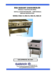
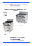
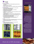
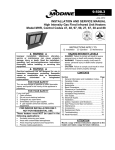
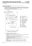
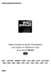
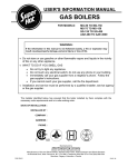
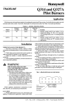
1
GAS FRYERS
PROUDLY AUSTRALIAN MADE
INSTALLATION PROCEDURE – USER MANUAL
SERVICE INSTRUCTION
MODELS FRG-1,2,3 – FRG-24,48,72
GAS APPROVAL NO. 2149/SC333
ESTABLISHED 1911
The Cooking Equipment Professionals
www.goldsteineswood.com.au
TABLE OF CONTENTS
1.
INTRODUCTION
Page 3
2.
INSTALLATION
Page 4 & 5
3.
COMMISSIONING
Page 6
4.
OPERATING INSTRUCTIONS
Page 7-8 & 9
5.
LIGHTING INSTRUCTIONS
Page 10
6.
DRAINING & FILTERING INSTRUCTIONS
Page 11 & 12
7.
TECHNICAL DATA
Page 13
8.
SERVICING
Page 14 & 15
9.
TROUBLE SHOOTING
Page 16-17 & 18
10.
WIRING DIAGRAM
Page 19
11.
CONTROLS
Page 20
12.
DRAWINGS
Page 21 & 22
13.
SPARE PARTS
Page 23 & 24
14.
WARRANTY
Page 25
15.
BRANCHES
Page 26
IM011B2/p2
1.
INTRODUCTION
Congratulations for purchasing your Goldstein commercial cooking appliance.
J. Goldstein & Co. is a wholly owned Australian company and has been
operating since 1911, building high quality products. The information in this
manual will assist your installer and ensure correct location and connection.
Thoroughly read the user instructions and the user maintenance sections, as
understanding your products, its operation, and its cleaning and service
requirements will provide you with long and satisfactory service. Failure to do
so could shorten the life of the product and decrease its efficiency. Please
ensure only authorised service technicians are called to any difficulties that
may arise.
INTRODUCTION
GOLDSTEIN DEEP WELL GAS RESTAURANT FRYER
MODELS FRG-1,2,3 - FRG-24,48,72
GOLDSTEIN FRYERS are designed to give long and satisfactory service and
incorporate the best possible materials and workmanship.
Proper
installation, adjustment and preventative maintenance are vitally important if
efficiency and appearance are to be maintained.
A freestanding 1,2, or 3 deep well automatically controlled gas-operated fryer.
The fryer is mounted on 4 legs with a clearance from floor of 152mm. The
fryer is equipped with a splash back incorporating a top venting flue outlet.
Pan outer case and outer surround of stainless steel, cooking pan of mild
steel, sand blast finish.
Read these instructions carefully as they contain important safety information
regarding the installation, use and maintenance of the appliance.
OIL TEMPERATURE
Keep the oil temperature in the fryer to a maximum of 190ºC. Higher temperatures
will cause rapid breakdown of the oil and give you no faster cooking.
At 205ºC to 210ºC the life of the oil is only one third of its life at 190ºC. In addition
increased decomposition causes the oil to smoke badly even if the temperature is
lowered to 190ºC again.
High temperatures give you no advantage, cost you money and increase the fire
danger.
“THE EQUIPMENT MUST BE INSTALLED BY A
LICENSED GASFITTER
IM011B2/p3
2. INSTALLATION
RECEIVING INSPECTION – PRE-INSTALLATION
• Check crates for handling damage.
After carefully uncrating, check for
“concealed” damage. Report any damage immediately to carrier and to dealer.
• Remove and check all loose items as found on back of Warranty Card.
• Check type and capacity of gas supply.
• The type of gas for which this fryer is factory adjusted can be seen on
the rating plate, located on the inside of the door.
PRE-INSTALLATION OF THE FRYER
• Check that there is sufficient clearance between doors and passageways to
move equipment into the cooking area.
• Check the rating plate to ensure appliance is suitable for the gas supply to which
it will be connected and for information relative to gas input pressure and
consumption.
• SPECIAL attention must be paid to fire hazards from combustible surfaces.
• REGULATOR (The fryer gas control incorporates a regulator so no regulator is
required to be connected into the supply line, unless supply gas pressure is
greater than 3.45 Kpa).
Assemble legs to fryer
Tilt fryer to rear and screw in 2 legs supplied. Tilt fryer to front then screw legs into
rear. The Fryer should be levelled left to right with a 3mm fall to the front.
Ventilation
Adequate ventilation must be provided, preferably by a hood with vent and exhaust
fan. Never make a direct connection between the flue of the appliance and the vent
flue. Refer AS 5601/AG601 Gas Installation Code.
INSTALLATION
NOTE:
IM011B2/p4
The appliance must be installed by an authorised person and in accordance
with the regulations of the local Gas Authority, AS5601/AG601 and any other
authority having jurisdiction. The appliance has been tested and preset
before leaving our factory, but small adjustments may be necessary to suit
local conditions.
Correct operation of the appliance must be tested as part of the installation
procedure.
2. INSTALLATION Cont’d
Please follow these instructions carefully
1.
Set unit in desired position. If rear wall is of combustible material ensure
there is a minimum distance of 100mm between the back of the unit and the
wall.
2.
Adjust feet till they are all touching the floor and using a spirit level from front
to rear and left to right. This operation is important as a floor variation of
25mm to 75mm in a floor is found to be not uncommon.
NOTE: The above levelling procedure is critical for the fryer to work
according to the manufacturers specifications.
3.
Have a licensed gas fitter or your Gas Company connect the appliance to the
mains supply. The fitting is 25mm BSP at the line up manifold and 19mm
BSP for rear gas entry. The appliance must be installed in accordance
with the rules of any authority having jurisdiction.
CAUTION
NEVER ALLOW BURNER TO OPERATE WITH FRYPOT EMPTY
THIS DAMAGES THE FRYPOT AND VOIDS WARRANTY
DO NOT TURN ON MAIN BURNER UNLESS THE OIL IS FILLED
TO THE CORRECT OIL LEVEL MARKED AT THE REAR OF PAN.
IF SOLID SHORTENING IS USED, BE CERTAIN SHORTENING IS
PRE-MELTED, OR AT LEAST TIGHTLY PACKED AGAINST THE
PAN SURFACE DIRECTLY ABOVE THE BURNER FLAME AND
TURN MAIN BURNER OFF IMMEDIATELY IF FAT BEGINS TO
SMOKE WHILE MELTING
NOTICE
PLEASE RETURN YOUR WARRANTY CARD
FAILURE TO DO SO WILL VOID WARRANTY
ON THE EQUIPMENT
IM011B2/p5
3. COMMISSIONING
COMMISSIONING APPLIANCE – DETAILS, TESTING, CHECKING
PRESSURE ETC.
COMMISSIONING CHECK LIST
1.
CHECK FOR DAMAGE AND MISSING PARTS.
2.
REMOVE ALL PLASTIC COATING FROM S/STEEL PANELS.
3.
MAKE SURE ALL PARTS ARE IN THEIR CORRECT POSITION E.G.
TRAYS BURNERS KNOBS.
4.
MAKE SURE ALL ELECTRIC AND GAS CONNECTIONS ARE CORRECT
AND TIGHT.
5.
LEVEL OFF UNIT LEFT TO RIGHT AND ALSO MAKE SURE THAT FRONT
IS JUST 3-4 MM LOWER TO ALLOW FOR FLUING.
6.
TURN ON GAS OR ELECTRICITY.
7.
ADJUST GAS PRESSURE WITH THREE-QUARTERS OF THE UNIT
RUNNING, ADJUST GAS PRESSYRE.
NATURAL GAS
LPG
1.00 KPA
2.75 KPA
8.
TURN ON ONE AT A TIME TO MAKE SURE ALL IS WORKING E.G.
BURNER, RADIANT, GRIDDLE AND OVEN.
9.
SHOW CUSTOMER
A)
B)
C)
D)
10.
HOW TO WORK EQUIPMENT
HOW TO CLEAN
HOW TO PULL IT APART E.G. TRAYS, TRIVETS.
ALSO WHAT NOT TO DO, E.G. WATER WITH ELECTRICAL,
GREASE AND OIL IN CONTROLS.
CHECK TO MAKE SURE MANUALS AND WARRANTY CARDS ARE
THERE.
ALSO GO THROUGH MANUAL WITH CUSTOMER E.G. LIGHTING,
CLEANING.
NOTE
WASH HOSES SHOULD NEVER BE USED ON THE APPLIANCE.
USE OF HOSES WILL VOID WARRANTY
IM011B12p6
4. OPERATING INSTRUCTIONS
1
OPERATING BEFORE FIRST USE
Clean protective oil from bright parts and interior of pan with a solution of washing
soda or other grease dissolving material. Drain through valve in bottom then rinse
thoroughly. (Note: It must be completely rinsed out for even a small particle of
cleaner in the pan will ruin the cooking medium). Also clean baskets and strainer.
Test all gas connections for leaks.
2.
FILLING
Fill pan to level indicated on back of pan. The FRG-1 size fryer takes approximately
20.8 Kgs of oil. It is a good idea to dip out several cupfuls of oil from your pan each
day and add fresh oil to replace it. This keeps acid content down and the oil will last
much longer. The oil dipped out can be used for general-purpose work and is not
wasted. Do not overfill your fryer pan. Overfilling causes “foam over” and messy
frying conditions. The FRG-1 takes approx. 30 litres of oil. The FRG-24 takes
approx. 40 litres.
3.
CLEANING
Your fryer pan deserves the same care you give your cooking pots. It should
be kept clean and bright. Oil in deep well fryer is a food and should be
handled with care.
DAILY OPERATION
OPENING:
At opening time, always visually check the fryer for:
a)
Combination or main gas valve “off”
b)
To light the fryer, see Page 17 or on back of door.
GENERAL USE OF THE FRYER:
a)
For consistent product quality, convenience and long-term savings, use a
high quality liquid frying compound.
b)
If using solid shortening, never attempt to melt a block of shortening by
setting it on base of Fryer Tank. This is inefficient, dangerous and will cause
damage to the frying vessel.
c)
Temperature of frying compound. Although 180 degrees is the usual
temperature recommended for most cooking operations, frying should be
carried out a lowest temperature, which will produce a high quality end
product while ensuring maximum life of the frying compound. When the fryer
is not in use, the temperature controller or operating thermostat should be set
lower than that used during cooking. Light loads, too, may be cooked at
lower temperatures. A good operator will experiment to determine the best
temperature and load conditions for the various foods to be cooked.
IM011B2/p7
4. OPERATING INSTRUCTIONS Cont’d
GENERAL USE OF THE FRYER cont’d
d.
Salting. Operators sometimes salt the food over the frying vessel. This
practice should be avoided, as salt deteriorates the frying compound quickly
and flavours everything being cooked, not just the batch being salted.
FILTERING
The frying compound should be filtered at least daily, or even more frequently if
cooking is heavy. This assures the longest life possible for the frying compound
gives a better taste to the food being prepared and minimizes flavours being
transferred from batch to batch.
When completing a filter cycle, always close the return valve(s) at the fryer (s) to
avoid siphoning oil out of the fryer into the filter and open the valve at the filter to
promote draining of the return lines into the filter pan.
If using solid shortening, always make sure he return lines are clear before turning
off the filter motor and hang any flexible lines up to drain. Solid shortening will
solidify as it cools and clog the lines.
CLOSING
When closing at night, filter the oil in all fryers and drain the filter lines. Cover the
open tanks of oil. Turn the power switch on the fryer panel “off” and turn the control
knob on the combination gas valve to “off”.
SHUT DOWN
When shutting down for longer than just overnight, drain the frying compound clean
the vessel thoroughly, either discard the frying compound or return it filtered to the
vessel and then cover it.
Turn the manual off/on valve on the incoming service line ”off”
CLEANING AND MAINTENANCE
GENERAL
Any piece of equipment works better and lasts longer when maintained properly and
kept clean. Cooking equipment is no exception. Your “Cool Zone” Deep Fat Fryer
must be kept clean during the working day and thoroughly cleaned at the end of
each day.
DAILY
a)
Remove and wash all removable parts.
b)
Clean all exterior surfaces of the body. Do not use cleansers, steel wool, or
any other abrasive material on stainless steel.
c)
Filter the cooking oil and replace if necessary. The oil should be filtered more
often than daily under heavy use.
IM011B2/p8
4. OPERATING INSTRUCTIONS Cont’d
WEEKLY
a)
Completely drain the fryer vessel into either the filter or steel contained. Do
not use a plastic bucket or glass container.
b)
Clean the vessel with a good grade of cleaner or hot water and a strong
detergent.
d)
Bring to a rolling boil, turn the heat down and let the mixture stand until
deposits and/or carbon spots can be rubbed off with the Teflon brush.
e)
Scrub the tank walls, then drain the vessel and rinse in clear water.
f)
Refill with clear water and boil again.
g)
Drain, rinse and dry thoroughly
h)
Refill with cooking oil or frying compound as directed above.
PERIODIC
Your “Cool Zone” Deep Fat Fryer should be checked and adjusted periodically by a
Qualified service personnel as part of a regular kitchen maintenance program.
STAINLESS STEEL
All stainless steel body parts should be wiped regularly with hot, soapy water during
the day and with a liquid cleaner designed for this material at the end of each day.
CAUTION do not let water splash into the tank of hot oil. It will splatter and can
cause severe burns.
DO NOT USE STEEL WOOL, ABRASIVE CLOTHS, CLEANSERS OR
POWDERS!
If it is necessary to scrape stainless steel to remove encrusted materials, soak the
area with hot cloths to loosen the material, and then use a wood or nylon scraper.
DO NOT USE a metal knife, spatula, or any other metal tool to scrape stainless
Steel. Scratches are almost impossible to remove
NOTE: “DO NOT SPRAY AEROSOLS IN THE VICINITY OF THIS APPLIANCE
WHILE IT IS IN OPERATION”
IM011B2/p9
5. LIGHTING INSTRUCTIONS
LIGHTING INSTRUCTIONS
AN ALUMINIUM PLATE INSCRIBED AS SHOWN HEREUNDER
LIGHTING, RELIGHTING AND SHUT DOWN INSTRUCTION
IMPORTANT: DO NOT TURN ON MAIN BURNER UNLESS
THE OIL IS FILLED TO THE CORRECT OIL
LEVEL MARKED AT THE REAR OF THE PAN
1.
Depress and turn gas valve knob to off position. If flame goes out
wait five (5) minutes before reigniting.
2.
Turn knob counter-clockwise to pilot position, depress knob
and light pilot. Continue to depress knob until pilot remains
alight when knob is released (approximately one minute).
Turn knob to ON position.
3.
Set thermostat as desired.
Thermostat will actuate gas flow to the main burner. For
temporary or permanent shutdown, depress and turn gas
Valve knob to OFF position.
JGSD-125-100-0
OVER TEMPERATURE SAFETY CONTROL
(Prevents fryer from going over 235°C) with bulb located front of pan Manual reset
control located underneath thermostat knob.
STRAINING EXCESS CRUMBS
Always drain fryer when cooking medium is warm and in liquid state. A cool fryer will
not drain thoroughly. Open drain valve fully and check for any particles or crumb
residue in valve seat. Clean out with wire or brush before closing.
Straining takes less time than cooking one load of potatoes and will pay dividends in
oil saving and food quality. Close valve and pour fat back into pan to continue day’s
work.
LIGHTING
Follow lighting instructions on plate fastened behind door of unit. (Note: Air trapped
in manifold system required bleed off before pilot burner will ignite causing initial
ignition to be abnormally slow
IM011B2/p10
6. DRAINING & FILTERING INSTRUCTION
A. DRAINING
WARNING
Draining and filtering of shortening must be accomplished with care to avoid the
possibility of a serious burn caused from careless handling.
WARNING
The burner MUST NOT be turned on when the fry pot is empty. A few minutes of
burner operation with an empty fry pot will destroy the fry pot and void the warranty.
1. USE PROTECTIVE CLOTHING GLOVES ETC WHEN HANDLING HOT
LIQUIDS.
2. Position a metal container with sealable cover under the drainpipe. The metal
container must be of sufficient design to withstand the hot shortening and
must be able to hold hot liquids holder and filter cone used when a filter
machine is not available. If you are using the filter cone holder and cone, be
sure that the cone holder rests securely on the metal container.
3. Open the drain slowly to avoid splattering. If splattering occurs, exercise
extreme caution.
3. If the drain valve becomes clogged with food particles, you may wish to use
the Poker like tool. This tool must be used from INSIDE the fry pot ONLY.
Do not hammer on the drain valve, as damage to the ball inside will cause it
to leak. DO NOT insert into front of drain valve in an attempt to unclog the
valve; hot shortening will rush out creating the potential for injury.
5.The drained shortening should be allowed to cool to (38ºC) or lower before
transporting the container and removing drain pipe. Shortening temperature
of
(60ºC) or higher will result in severe burns.
6. After draining the shortening, clean all food particles and residual shortening
from the fry pot before refilling.
7. Close the drain valve and refill the fry pot with clean, filtered shortening.
WARNING
IF GAS ODOURS ARE DETECTED, THE FRYER GAS SUPPLY MUST BE SHUT
OFF AT THE MAIN SHUT-OFF VALVE AND THE LOCAL GAS COMPANY OR
AUTHORIZED SERVICE AGENCY CONTACTED FOR SERVICE.
IM011B2/p11
6. DRAINING & FILTERING INSTRUCTIONS Cont’d
B. BOILING OUT THE FRYPOTS
Clean new fry pots as follows before filling with shortening:
1.
Before operating the burner, close fryer drain valve and fill empty fry pot with
a mixture of cold water and boil-out washing soda solution. Fill to the fry pot
OIL-LEVEL LINE.
2.
To light fryer, follow LIGHTING INSTRUCTIONS on back of fryer door.
3.
Turn the fryer gas valve knob to the ON position. Set thermostat knob to
(135º).
4.
Simmer the solution for one hour. Caution: NEVER leave the fryer
unattended during the boil-out procedure because the solution will foam up
and overflow. To control this condition, turn the fryer gas valve knob to the
PILOT position occasionally.
5.
After the solution has simmered for one hour, turn the fryer gas valve knob to
the PILOT position and allow the solution to cool.
6.
Add (3.8 litres) of cold water and stir. Drain out the solution into a suitable
container and clean the fry pot thoroughly.
7.
Close the drain valve and fill the fry pot with clean water. Using a fry pot
cleaning brush, rinse the fry pot thoroughly. Drain and wipe down with a
clean, dry towel.
CAUTION
ALL DROPLETS OF WATER MUST BE REMOVED FROM THE FRYPOT
BEFORE FILLING WITH SHORTENING.
C.
FILLING WITH SHORTENING
TURN OFF PERIOD
1.
Make sure fryer gas valve knob is at the OFF or PILOT position.
2.
Close fry pot drain valve, remove basket support rack if required.
3.
Fill empty fry pot to the OIL-LEVEL LINE. When solid shortening is used, it
must be thoroughly packed down into the fry pot cold zone.
4.
To melt solid shortening without scorching, the burner should be turned on for
about (3) seconds and OFF for about (10) seconds alternately until melted. If
any smoke is seen during this turn the gas supply OFF.
IM011B2/p12
7. TECHNICAL DATA
C. GAS/INJECTOR DETAILS TABLE
Model
Gas Type
T.P.P.
Mj
Pilot No.
N.G.
2.85
1.00
80
2.6
L.P.G.
1.80
2.65
80
1.6
FRG
Injector (mm)
DIMENSIONS TABLE
WIDTH
(mm)
DEPTH
(mm)
HEIGHT
(mm)
1
FRG
2
1L
FRG
2L 3L
3
457
914
1372
704
704
1120
1120
24
FRG
48
72
457
914
1372
704
800
800
1120
1120
1120
24L
FRG
48L
610
1220
1830
72L
610
1220
1830
800
704
704
704
800
800
800
1120
1120
1120
1120
1120
1120
1120
CONVERSION INSTRUCTIONS N.G. TO L.P.G.
1
Remove injectors from burners and change injector to suitable orifice (see
gas injectors details table above).
2.
Remove pilot assembly. Change pilot injector NG= 2.6 LP = 1.6
Stamped on head pilot this Number not a dimension.
3.
Re-assemble pilot assembly.
4.
Remove the regulator cover screw.
5.
Insert the spring and pin from the F92-0737 N.G. to L.P.G. conversion kit.
6.
Install regulator cover screw onto regulator.
7.
Affix caution label to top of cover screw.
8.
Check all connections for leaks.
9.
Adjust the T.P.P. to suit L.P.G.
10.
Change Rating Plate.
IM011B2/p13
8. SERVICING
ACCESSING FRYERS FOR SERVICING
WARNING
Moving a fryer filled with hot shortening may cause splattering of the hot shortening.
Extreme care must be exercised.
1.
2.
3.
4.
Disconnect quick-disconnect hose.
Remove restraining devices typically applied to the bottom or back of
fryer.
Relocate fryer so that access can be obtained to perform necessary
maintenance.
After servicing has been completed, reconnect quick-disconnect hose;
and attach restraining devices.
SHUTTING FRYER(S) OFF FOR SHORT PERIODS
1.
2.
Open fryer door(s) and rotate gas valve knob(s) to the PILOT position.
Place fry pot covers in place if equipped. (OPTIONAL EXTRA)
SHUTTING FRYER(S) OFF WHEN CLOSING STORE
1.
2.
3.
4.
Open fryer door(s) and rotate gas valve knob(s) to the PILOT position.
Depress gas valve (knob(s) and slightly rotate clockwise.
Release and continue rotating clockwise to OFF.
Place fry pot covers in place if equipped. . (OPTIONAL EXTRA)
VENTILATION AND CLEARANCE.
One of the important considerations of efficient fryer operation is ventilation. The
fryer must be installed so that products of combustion are removed efficiently and
the kitchen ventilation system does not produce drafts that interfere with the proper
burner operation. The fryer flue opening must not be placed close to the intake of
the exhaust fan.
The fryer must never have its flue extended in a “chimney” fashion. An extended
flue will change the combustion characteristics of the fryer causing it to be slow to
recover and frequently causing delayed ignition.
IM011B2/p14
8. SERVICING Cont’d
RECOMMENDED SPARE PARTS
•
•
•
•
•
To ensure minimum downtime of the fryer in case the replacement of a part
is required. It is recommended that one each of the following parts be kept
in local stock.
High temperature limit control.
Gas safety control valve
Thermocouple
Operating thermostat
Illustrations and complete listing of replaceable parts are on pages
FACTORY SERVICE & PARTS ORDERING
SERVICE PROBLEMS
Contact the factory direct by mail or telephone ( no collect calls accepted). Always
give the model and serial numbers of your fryer.
PARTS ORDERING
Customers may order parts directly from their local Authorised Parts Distributor.
For this address and phone number, call the factory. Factory address and phone
numbers are on the back of this manual.
IMPORTANT
GOLDSTEIN & CO WHOSE POLICY IS ONE OF CONSTANT IMPROVEMENT,
RESERVES THE RIGHT TO AMEND SPECIFICATIONS OF ANY PART OR
ASSEMBLY AND THE MATERIALS AND FINISHES COMPRISING THE COOL
ZONE FRYER AND ITS ACCESSORY EQUIPMENT WITHOUT PRIOR NOTICE.
IM011B2/p15
9. TROUBLE SHOOTING
TROUBLE SHOOTING.
These troubleshooting procedures must be carried out only by a Goldstein
Authorised Maintenance & Repair Centre or Company specialising in restaurant
Cooking appliances. The problems and possible solutions given below cover those
Most commonly encountered.
FACTORY APPROVAL MUST BE OBTAINED PRIOR TO ANY WARRANTY
WORK BEING DONE OR GOLDSTEIN CANNOT BE HELD RESPONSIBLE.
PILOT BURNER MALFUNCTIONS
a)
Pilot will not ignite
No evidence of gas at
*
Check that gas valve is open and
gas is present at that valve.
*
Remove pilot gas supply line and
gas check for Dirt.
*
Blow out if necessary then reinstall.
b)
Pilot burner ignites but will
not remain lit when gas cock
Manual knob is released.
*
Check pilot burner orifice for dirt.
*
Check that the thermocouple leads
are firmly screwed into pilotstat
power unit bushing on gas control.
*
Remove end of thermocouple lead
from Pilotstat power unit bushing
and clean with fine sandpaper. Also
check that bushing is clean.
*
Thermocouple defective – replace.
*
Pilot flame may be too high or too
low. adjust flame by turning pilot flow
adjustment on Valve. Also check
over-temperature thermostat reset
button if tripped. Manually reset by
pushing button home.
*
Check milivolts on Power Generator
should be 550-600 with Thermostat
off.
*
Check millivolts on Power generator
with valve on should be no lower
than 220 mv
IM011B2/p16
9. TROUBLE SHOOTING Cont’d
c)
Pilot flame of proper size but
unstable. Flame wavers and
does not envelope the
thermocouple completely at
all times.
*
Check for drafts which might be
caused air conditioning equipment
or make-up air apparatus. Turn
these off and recheck the pilot.
MAIN BURNER MALFUNCTIONS
a)
Main burner will not come on; *
No gas present at main burner.
*
*
b)
d)
be
Main burner flames are small
and appear lazy; frying
compound does not come up
to temperature quickly.
Signs off excessive tem-
Check that the pilot is ignited and
is operating properly. The
combination gas Control valve may
be defective; replace if necessary
(Check owners replacement part
stock)
Check the high temperature safety
switch. Replace if defective.
*
Check gas pressure at the pressure
tap of the combination gas valve
(refer to the illustration of the
Manufacturer’s bulletin). Use a
standard water type U-gauge
manometer. With the burner in
operation, the pressure should be
1.00 kPa and 2.75 kPa on natural
and propane gas respectively.
If not, unscrew cover of pressure
regulator adjustment. Use screwdriver to turn adjusting screw clockwise to increase gas pressure to
burner (or counter clockwise to
to decrease the pressure).
*
Replace cover & plug.
*
Check operating thermostat. May
perature, frying compound
scorches and quickly was
discoloured.
IM011B2/p17
Check that gas valve is open.
out of calibration. Recalibrate in
accordance with instructions
Provided with thermostat when Fryer
purchased.
*
Check gas pressure as outlined
above.Cooking compound of interior
quality or used too long. Replace.
*
Cooking compound of inferior
quality or used too long. Replace.
9. TROUBLE SHOOTING Cont’d
CAUTION
DO NOT ATTEMPT TO TURN THE ADJUSTMENT PAST THE STOPS OR THE
CONTROLLER WILL BE DAMAGED
e)
Fryer will not reach
temperature setting and/
or runs erratic.
f)
Fryer temperature cannot
be controlled runs to high
limit temperature.
g)
Pilot will not stay on
IM011B2/p18
*
Operating thermostat
Operating thermostat
*
Oil level too low
*
Oil was drained when still hot.
*
Solution – reset over temp control
by removing hexagon nut
underneath thermostat knob and
press button in finger to reset
controller. As On Site Fryer Test
must be carried out to ensure that
problem has been resolved.
10. WIRING DIAGRAM
WHITE RODGERS CONTROL
IM011B2/p19
11. CONTROLS
OFF
PI
LO
T
ON
LIGHTING, RELIGHTING AND SHUT DOWN INSTRUCTION
IMPORTANT: DO NOT TURN ON MAIN BURNER UNLESS
THE OIL IS FILLED TO THE CORRECT OIL
LEVEL MARKED AT THE REAR OF THE PAN
1.
Depress and turn gas valve knob to off position. If flame goes out
wait five (5) minutes before reigniting.
2.
Turn knob counter-clockwise to pilot position, depress knob
and light pilot. Continue to depress knob until pilot remains
alight when knob is released (approximately one minute).
Turn knob to ON position.
3.
Set thermostat as desired.
Thermostat will actuate gas flow to the main burner. For
temporary or permanent shutdown, depress and turn gas
Valve knob to OFF position.
JGSD-125-100-0
IM011B2/p20
12. DRAWING
FRG-24,FRG-24L
704
1120
800
1120
610
GASINLET
19mmBSP
245
FRG-24(L)
FRONTVIEW
IM011B2/p21
195
195
GASINLET
19mmBSP
280
FRG-24
SIDEVIEW
GASINLET
FRG-24L
SIDEVIEW
12. DRAWING
26
24
23
25
23
40
19
18
39
11
39
10
22
21
28
20
16
1
12
27
8
5
2
14
36
29
30
13
15
1
17
2
36
4
32
6
3
33
7
31
35
46
47
51
50
16
52
44
33
42
34
48
49
45
43
IM011B2/p22
38
37
24
13 SPARE PARTS
MODEL: FRG-1, FRG-1L
ITEM No.
1.
2.
2.
3.
4.
5.
6.
7.
7.
8.
10.
11.
12.
13.
14.
15.
16.
16.
17.
18.
19.
20.
21.
22.
23.
24.
24.
25.
26.
27.
28.
29.
30.
31.
32.
33.
33.
34.
35.
36.
37.
38.
39.
40.
41.
42.
43.
44.
CODE
GBNFRS00
GIJFR180
GIJFR285
GPIC0007
GPG00900
GPIB0005
GCUFRG00
GPU00001
GPU00002
EPR00101
MTH20205
MKNEP001
MKNPLTS8
MTH00245
ESPLO402
ESP00003
MTAC0025
MTAC0026
FRE18T09
MGLFG00B
MWS00007
GNT00042
MGLFG00A
FRG18P16
MBKFG180
FRG18P27
TGT18P48
FRG18P17
MHDCP001
MHDPL095
MCA00002
MLEPLA01
MLEPLBF1
MSP00009
FRG18A09
MKNPLFR1
MKNPLFRP
ESP00016
GCU00008
MGK00022
MTH00200
MKNFR000
MWS00004
MWS00005
MCK00002
GCUMI002
ESP00006
ESPL0006
IM011B2/p23
DESCRIPTION0
BURNER – FRG (SQUARE AERO BURNER) (26.37MJ)
INJECTOR – FRG 1.80mm L/P
INJECTOR – FRG 2.85mm N/G
ELECTRODE – CERAMIC
GENERATOR – POWER L=900 FRG
BODY – PILOT GPI00005 (WING PILOT)
CONTROL UNIT – GAS FRG ¾” VALVE – STANDARD
PILOT SPUD L.P.G 1.6
PILOT SPUD N/G 2.6
PROBE – 4mm K THERMOCOUPLE, SUIT CONTROL ETC00892
THERMOSTAT – FRG/TGF (95~205 x C) (COLD CON.)
PLATE – ESCUTCHEON
KNOB – FRG THERMOSTAT
THERMOSTAT – GAS OVERTEMP. (245 °C)
LEAD –H/T 400 FOR SPARKER
SPARKER – PIEZO C/W SPRING, WASHER, NUT
BALL VALVE 1” SHORT “T” HANDLE
BALL VALVE 1” LONG HANDLE
DRAIN PIPE
GLAND – FRG PART – B
FLAT WASHER FOR MGLFG00B
LOCK NUT FOR MGLFG00B
GLAND – FRG PART – A
SCRAP ARRESTOR
BASKET – FRG18 (STANDARD)
BASKET HOLDER (OLD)
BASKET HOLDER (NEW)
NIGHT COVER
HANDLE – 266 76 x 8 C/P STEEL (FR)
HANDLE – PLASTIC 3 7/8” (98mm) BLACK FRG DR
CATCH – DOOR MAGNET (FRYER)
STAINLESS STEEL LEG WITH ADJ PLASTIC INSERT
FEET – PLASTIC BULLET 2D
SPRING AND CIRCLIP ASSY FOR MKNPLFRP OLD TYPE
MANIFOLD ASSY 1
KNOB – FRG GAS CONTROL UNIT
KNOB – FRG GAS CONTROL UNIT (OLD STYLE)
SCARICO BOX FOR GAS – ELECTRIC
W/R CONTROL FOR AS ELECTRIC 36C63H435
GASKET FOR INJECTOR 1.80 – 2.85
THERMOSTAT – 145~200 x C WHITE ROGER 2B61-994
KNOB – SUIT 2B61-994 FRYER THERMOSTAT
BRASS WASHER FOR GLAND
RUBBER WASHER FOR GLAND
L.P.G CONVERSION KIT FOR WR438
CONTROL UNIT – GAS MINISIT 120 x ~200 x C (FRYER)
SPARKER – C/W COVER FOR GCUMI001/3 (MINISIT)
LEAD – H.T L=1000mm FOR SPARKER ESP00006
13. SPARE PARTS-Cont’d
MODEL: FRG-1, FRG-1L CONT.
ITEM No.
45.
46.
47.
48.
49.
50.
51.
52.
IM011B2/p24
CODE
GCU00003
ETC00891
EPR00100
MKNPLMS2
GET00005
ETC00892
EPR00102
ETC00893
DESCRIPTION
BULB & CAPILLARY FOR MINISIT
CONTROL – DIGITAL SIT 891 FRYER FRE-D
PROBE – 4mm FOR SIT 891 FRYER FRE-D
KNOB – MINISIT (120 x~200 x C)
ELECTRODE – CERAMIC HEAT ROD SENSOR
CONTROL UNIT – CAHO SR-T701 (UNIT K)
FRYER PROBE – FRE WITH 3 WIRES PT THERMOCOUPLE
CONTROL UNIT – FRE PT 100
14. WARRANTY
installation must be carried out according to local regulations by qualified trade
persons.
Isolating switch(es), shut-off valves etc must be within easy reach of the machine for
future service and maintenance requirements.
If in doubt call GOLDSTEIN/ESWOOD or their representative for further information.
No responsibility will be accepted for defects or damages by improper installation,
for changes to the product not authorised by GOLDSTEIN/ESWOOD or for
operation outside the technical specifications.
GOLDSTEIN/ESWOOD warrants their products to be free from defects in material
and workmanship under “normal use and service”. This does not include normal
wear and tear of parts. GOLDSTEIN/ESWOOD will repair or replace any parts,
which in GOLDSTEIN/ESWOOD’s sole judgement are defective in material or
workmanship, in accordance with the warranty offered.
This undertaking covers the provision of labour and parts for 12 months from the
date of delivery to the purchaser. This undertaking applies only to state capitals.
Remote areas are not covered by this commitment and special enquiries should be
made. (Note: Travel time not covered by warranty).
“To the maximum extent permitted by law, any liability on Goldstein/Eswood’s part or
on the part of its servants or agents for loss or damage of any kind whatsoever in
connection with the products, including liability for or in respect of any claim arising
out of contract, negligence or statute, shall not, in any event, exceed $100”
Labour under warranty is supplied free of charge during normal working hours,
Monday to Friday. Should warranty work be requested outside of our normal
working hours a labour charge will be applied equivalent to a normal hour rate,
without out of hours penalty rates. Refer to last page of this manual for your closest
branch for warranty repair services).
IM011B2/p25
15. GOLDSTEIN/ESWOOD BRANCHES
For inquiries please call your nearest state branch:
Head Office
211-213 Woodpark Road
Smithfield New South Wales 2164
Phone:
02 9604 7333
Fax:
02 9604 5420
Victoria
Unit 13
260-264 Wickham Road
Moorabbin
Victoria 3189
Phone:
03 9553 1488
Fax:
03 9553 0785
Queensland
Nautilus Complex
Unit 12
210 Queensport Road
Murarrie Qld 4172
Phone:
07 3890 1811
Fax:
07 3890 1788
South Australia
Suite 26
283-287 Sir Donald Bradman Drive
Brooklyn Park
South Australia 5032
Phone:
08 8238 3423
Fax:
08 8238 3400
Western Australia
Unit 1/10 Wittenberg Drive
Canning Vale
Western Australia 6155
Phone:
08 9456 0559
Fax:
08 9456 0554
IM011B2/p26