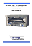
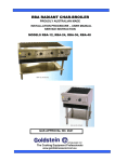
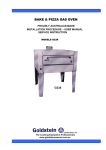
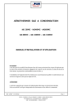
1
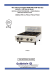
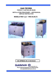
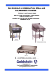
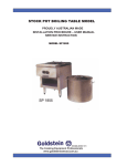
The Heavyweight 800 Series Performance Plus
And Fan Forced Units
PROUDLY AUSTRALIAN MADE
INSTALLATION PROCEDURE – USER MANUAL
SERVICE INSTRUCTION
MODELS PF-6-28, PF-12G-4-28, PF-24G-2-28, PF-36-28, PF-4-28
FAN FORCED
WINER OF
AUSTRALIAN
DESIGN COUNCIL
AWARD 1990
PF-6-28
PF-4-20
GAS APPROVAL 20” No.2494 28” 2498
ESTABLISHED 1911
The Cooking Equipment Professionals
www.goldsteineswood.com.au
TABLE OF CONTENTS
1.
INTRODUCTION
Page 3
2.
INSTALLATION
Page 4 & 5
3.
COMMISSIONING
Page 6
4.
MAINTENANCE
Page 7
5.
TRIVETS
Page 8
6.
PILOT & BURNER OPERATION
Page 9
7.
CONTROL
Page 10
8.
THERMOSTAT SETTING
Page 11 – 12 - 13
9.
PROBLEM SOLVING
Page 14 – 15 - 16
10.
FAN FORCE
Page 17
11.
FAN FORCE WIRING DIAGRAM
Page 18
12.
DRAWINGS
Page 19
13.
SPARE PARTS
Page 20 & 21
14.
WARRANTY
Page 22
15.
BRANCHES
Page 23
IM036B2/2
1. INTRODUCTION
Congratulations for purchasing your Goldstein commercial cooking appliance.
J. Goldstein & Co. is a wholly owned Australian company and have been
operating since 1911, building high quality products. The information in this
manual will assist your installer and ensure correct location and connection.
Thoroughly read the user instructions and the user maintenance sections, as
understanding your products, its operation, and its cleaning and service
requirements will provide you with long and satisfactory service. Failure to do
so could shorten the life of the product and decrease its efficiency. Please ensure
only authorised service technicians are called to any difficulties that may arise.
INTRODUCTION
GOLDSTEIN HEAVYWEIGHT 800 SERIES PERFORMANCE PLUS &
FAN FORCED UNITS
MODELS PF-6-28, PF-12G-4-28, PF-24G-2-28, PF-36G-28, PF-4-28.
GOLDSTEIN RANGES designed to give long and satisfactory service and
incorporate the best possible materials and workmanship. Proper installation,
adjustment and preventative maintenance are vitally important if efficiency and
appearance are to be maintained.
Read these instructions carefully as they contain important safety information
regarding the installation, use and maintenance of the appliance.
RECEIVING INSPECTION
• Check crates for handling damage. After carefully uncrating, check for “concealed”
damage. Report any damage immediately to carrier and to dealer.
• Remove check all loose items from unit and check contents as found on back of
warranty cards.
• Check type and capacity of gas supply.
• The type of gas for which this 800 Series is factory adjusted can be seen on the
rating plate, located on the bottom front panel of the Range.
IMPORTANT
A CLEANER THAT IS COMPATIBLE WITH ALUMINIUM MUST BE USED ON THE
EQUIPMENT OTHERWISE THE GAS PIPING WITHIN THE UNIT WILL BE DAMAGED
AND THIS WILL AUTOMATICALLY VOID THE WARRANTY.
“THE EQUIPMENT MUST BE INSTALLED BY A LICENSED GASFITTER AND
LICENSED CONTRACTOR”
IM036B2/3
2. INSTALLATION
RECEIVING INSPECTION – PRE-INSTALLATION
•
•
•
•
•
•
•
•
•
•
•
•
•
•
Please follow these instructions carefully.
Remove cartons from unit and check for any damages.
Report any damages to the transport company or your dealer.
Lift off base and screw the adjustable legs on the unit,
Set unit into correct position.
Adjust feet till they are touching the floor and using a spirit level, level from left to
right.
Also adjust front to back with a fall of about 2-3mm to the front to help fluing of the
unit.
This operation is important as variation of 25mm to 76mm in a floor level is found to
be common.
Make sure unit is under an exhaust hood that provides adequate ventilation.
Check date plate to ensure appliance is suitable to the gas that it is being connected
to.
The Rating Plate is located on the front bottom left side and has what the unit is set
up for as factory set and tested.
Check all loose items listed on the back of the Warranty Card.
Have your electrician connect a power point as per Electrical Authority and Local
Laws.
Note: The appliance must be installed by an Authorised person and in accordance
with the regulations of the local Gas Authority AS5601/AG601 and any other
authority having jurisdiction
The appliance has been tested and preset before leaving our Factory, but small
adjustments may be necessary to suit pressure supply.
Correct operation of the appliance must be tested as part of the installation
procedure.
1. Have a licensed gas fitter or your Gas Company connect the appliance to the
gas supply, Location of the connection is on the left side 381mm from the rear
and approximately 114mm from the floor. The fitting is 19mm BSP. The
appliance must be installed in accordance with the rules of any authority
having jurisdiction.
2. The pressure regulator (NG) and LPG standards (AS4563/AG300 1.1.05) are
supplied as a loose item and a hand stop tap must be supplied as close to the
appliance as possible to stop and pressure drop.
IM036B2/4
2. INSTALLATION
INSTALLATION
Please follow these instructions carefully
All equipment must be sitting level for proper operation and combustion where plinth
type installation is made, plinth height and front overhang must be 50 mm minimum.
Levelling can be made by the use of metal shims. For performer series where adjustable
legs are provided, levelling can be made easily due to the threaded construction of the
legs.
LIGHTING INSTRUCTIONS
1.
All range and roast ovens are complete with instructions on a Decal attached to
the appliance on the front stainless fascia.
2.
Performer range top arrangement:
A. All open burners may be ignited by the constant pilots.
B. Griddle top and hot top sections are provided with flame failure device gas
cocks Model 21S and is ignited by Piezo ignition.
ADJUSTMENT
Adjustments to burners and burner pilots can be made when necessary by any
qualified service organisation or your local gas utility service department.
NOTICE
PLEASE RETURN YOUR WARRANTY CARD
FAILURE TO DO SO WILL VOID WARRANTY
ON THE EQUIPMENT
IM036B2/5
3. COMMISSIONING
To be carried out be Gasfitter or Authority service person
COMMISSIONING APPLIANCE – DETAILS, TESTING, CHECKING PRESSURE ETC.
COMMISSIONING CHECK LIST
1.
CHECK FOR DAMAGE AND MISSING PARTS ON BACK OF WARRANTY
CARD.
2.
REMOVE ALL PLASTIC COATING FROM S/STEEL PANELS.
3.
MAKE SURE ALL PARTS ARE IN THEIR CORRECT POSITION E.G. TRAYS
BURNERS KNOBS.
4.
MAKE SURE ALL ELECTRIC AND GAS CONNECTIONS ARE CORRECT AND
TIGHT.
5.
LEVEL OFF UNIT LEFT TO RIGHT AND ALSO MAKE SURE THAT FRONT IS
JUST 3-4 MM LOWER TO ALLOW FOR FLUING.
6.
TURN ON GAS OR ELECTRICITY
7.
ADJUST GAS PRESSURE WITH THREE-QUARTERS OF THE UNIT RUNNING,
ADJUST GAS PRESSURE.
NATURAL GAS
LPG
1.00 KPA
2.70 KPA
8.
TURN ON ONE AT A TIME TO MAKE SURE ALL IS WORKING E.G. BURNER,
RADIANT, GRIDDLE AND OVEN.
9.
SHOW CUSTOMER
A)
B)
C)
D)
10.
HOW TO WORK EQUIPMENT
HOW TO CLEAN
HOW TO PULL IT APART E.G. TRAY, TRIVETS
ALSO WHAT NOT TO DO, E.G. WATER WITH ELECTRICAL, GREASE
AND OIL IN CONTROLS.
CHECK TO MAKE SURE MANUALS AND WARRANTY CARDS ARE THERE.
ALSO GO THROUGH MANUAL WITH CUSTOMER E.G. LIGHTING,
CLEANING.
NOTE
WASH HOSES SHOULD NEVER BE USED ON THE APPLIANCE.
USE OF HOSES WILL VOID WARRANTY.
IM036B2/6
4. MAINTENANCE
MAINTENANCE PROCEDURE
USE PROTECTIVE CLOTHING FOR CLEANING TO AVOID DANGEROUS CONTACT
WITH HOT SURFACES.
1.
CAST IRON TRIVET
Wash in WARM soapy water, use Plastic Scourer if necessary. Dry with soft cloth
or paper towel.
2.
STEEL GRIDDLE PLATES, ALL RANGES & GRIDDLE UNITS
Before daily cleaning of the griddle plate, cool the plate to no more than 60C.
Cooling can be accelerated using water applied with a brush or well wetted cloth
whilst wearing gloves. DO NOT pour quantities of water direct onto a hot griddle
plate, as scalding may result.
NB EMPTY THE WASTE GREASE CAN BEFORE WASHING DOWN!!!
3.
RANGE OVENS
The interior surfaces of the oven are porcelain enamel and can be cleaned with
soap and hot water or any approved oven cleaner. The base and two sides are
removable.
4.
HOT TOP PLATES (Target Top)
A.
B.
C.
5.
Burner under the hot top section should be turned on low for the initial
breaking-in. Gradually increase the heat for approximately six hours until
maximum temperature for heavy duty cooking has been reached.
Care of top plate should be limited to periodic wiping off with rough cloth or
burlap.
Do not use water, either hot or cold, to clean plates.
STAINLESS STEEL
Using a liquid cleaner indicated especially for this type metal can clean the
stainless steel finish. NEVER attempt to clean stainless steel with steel wool,
abrasive cloth or powders.
6.
PERIODIC CLEANING.
Keep grease, spillovers and other accumulations out of both top and oven burner
boxes or areas. The exterior painted surface of all appliances can be cleaned
with warm water and soap or a mild detergent. Removable drip or grease pans
are easily cleaned with warm water and soap or a mild detergent.
OPERATIONAL PROBLEMS AND SERVICE
No service is anticipated. However, should the occasion arise that service is required,
call a qualified gas service organisation or your local gas utility service department
DO NOT USE STEEL WOOL, ABRASIVE CLOTHS, CLEANSERS OR POWDERS!
If it is necessary to scrape stainless steel to remove encrusted materials, soak the
area with hot cloths to loosen the material, and then use a wood or nylon scraper.
DO NOT USE a metal knife, spatula, or any other metal tool to scrape stainless
Steel. Scratches are almost impossible to remove
IM036B2/7
5. TRIVETS
ENSURE ALL TRIVET ARE PUT ON AS PER DIAGRAM ABOVE, SO
THAT THE PILOTS ARE UNDER THE CANOPIES.
FAILURE TO PLACE TRIVET CORRECTLY MAY CAUSE A FIRE
HAZARD.
IM036B2/8
6. PILOT OPERATION
A
Q
B
XC
XD
A=
B=
C=
D=
OFF
IGNITION POSITION – LIGHT PILOT – (If flame failure hold in for 10 seconds
to establish pilot flame).
TURN TO FULL ON – MAX GAS FLOW, FURTHER ADJUSTMENT BETWEEN
POSITIONS C & D.
TURN TO MINIMUM FLOW – MIN. GAS FLOW TO MAINTAIN FLAME
(Adjustable to suit type of gas used.) as precise and accurate.
TO OPERATE:
Push in and turn knob to position “B”, light pilot burner and hold in for 10 seconds
to establish Pilot flame, release (pilot burner should remain alight) and turn to
position “C” for full flow of gas, for minimum gas flow turn to position “D”
(Adjustable to suit type of gas used). Further adjustment of gas flow between
position C & D.
IM036B2/9
7. CONTROL
MODEL EUROSIT 630 OVEN CONTROL
IM036B2/10
7. THERMOSTAT SETTING
SETTING
The thermostat must be set for an individual appliance at the factory.
However, if necessary an authorise person can recalibrate as follows:
♦ Remove knob 1
♦ Remove nut 2 and 7mm hexagonal spanner
♦ Operate the appliance until an oven temperature of 200°C is reached (or 160°C for a
fryer)
♦ When the appropriate temperature for the appliance is reached on test thermometer,
slowly rotate Pawl 3 towards the “OFF” position until the main burner snaps off.
Remove Pawl 3 from the splined adjusting screw and relocate so that when Knob 1 is
replaced the correct temperature mark on the Knob 1 corresponds to the oven (or
fryer 0 temperature.
♦ All components are re-assembled in the reverse order.
LOW FIRE ADJUSTMENT
Low fire is regulated by means of the “Min” screw only when the thermostat bulb
temperature is within the range of the control.
• Turn knob 1 to “OFF” position and remove
• Remove the cover by loosening the two fixing screws
• Turn Pawl 3 slowly until the instant that the valve snaps open to give minimum flame
on the main burner]
• To reduce the flame - turn “Min” screw in clockwise direction
• To increase the flame - turn “Min” screw in anticlockwise direction
• The correct flame is achieved when the burner will ignite from the pilot and extinguish
without noise and without burning back on the injector.
• Replace cover and knob 1 in reverse order.
PILOT GAS ADJUSTMENT
• To reduce pilot flame turn “Pil” screw clockwise
• To increase pilot flame turn “Pil” screw anticlockwise
• The pilot flame should be adjusted in conjunction with the air shutter provided on the
pilot to achieve a firm stable flame impinging on the tip of the thermocouple (the last
5-7mm).
IM036B2/11
8. THERMOSTAT SETTING Cont’d
INSTALLATION
630 EUROSIT complies with current safety standards.
Nevertheless, its installation on appliances must be verified in accordance
with specific standards for each installation. In particular, it is necessary
to ensure that requirements relating to the class of flame failure device are
met. All the installation, setting and adjustment operations must be carried
out exclusively by qualified personnel on the basis of the specific characteristics
of the appliance. The valve is not for outdoor use.
MECHANICAL CONNECTIONS
General recommendations
Do not tamper with sealed parts. Do not slacken assembly screws. Do not remove
labels. Avoid blows (knocks, falls etc.). Only remove dust caps when installing.
Do not exceed recommended torques. Ensure that the gas flows in the direction
shown by the arrow on the valve body. Prevent foreign matter from getting into the
valve during installation. In particular, check the cleanliness of the inlet and outlet pipes.
Do not subject the valve to bending in excess of 35 Nm and to torque in excess of 25Nm.
Use only the specified spanner grips when making the connections. The valve has three
pairs of retaining holes.
Main gas connection
The connection must be made using gas pipes with Rp 3/8 ISO 7 thread. Torque 25Nm.
Alternatively, it is possible to use nut and olive connections for Ø 12mm pipe (code
nos.0.958.025 and 0.957.007) (torque 15 Nm) The valve has two main gas inlets (10
and 12) and two outlets (11 and 13). The outlets which are not used must be sealed by
screwing the special plug (code 0.972.061) in flush Torque 7 Nm.
Connection to pilot burner
Ø 4mm, 6mm and ¼” pipes can be used. Use appropriately sized nut and olive. Tighten
to 7Nm torque. After making the gas connections, check seals and ensure appliance
works properly.
IM036B2/12
8. THERMOSTAT SETTING Cont’d
SETTINGS AND ADJUSTMENTS
All adjustments must be made on the basis of the specific characteristics of the
appliance.
Check inlet and outlet pressure using the pressure test points (6 and 7) provided.
After testing, carefully seal test points with the provided screws. Recommended
Torque: 2.5Nm.
Adjustment of maximum and minimum outlet flows
These adjustments must be carried out with the thermostat bulb cold.
Maximum flow
Turn the knob to position 7.
Turn the setting screw (2) fully in.
Turn the setting screw anticlockwise to increase gas flow.
CAUTION: The setting screw should not be unscrewed more than 2 turns from the fullyin position.
Minimum flow
Starting from position 7, turn the knob slowly clockwise to the minimum flow position
(just before the cut-off click).
Turn the screw (3) clockwise to reduce flow.
It is possible to use screws with calibrated bores (available on request) to replace the
Maximum by-pass flow setting screw. In this case it is necessary to screw the calibrated
screw fully in with 7 Nm torque.
Adjustment of gas flow to the pilot burner
Turn the screw (5) clockwise to reduce flow.
IMPORTANT: At the end of all setting and adjustment operations, check gas seals
and the efficiency of the appliance.
After carrying out all adjustments, fit the provided seals and/or block the setting screws
with paint.
IM036B2/13
9. PROBLEM SOLVING
CAUSE AND REMEDY FOR DEFECTIVE OVEN COOKING
1.
2.
3.
Too much bottom heat, which results in burning on the bottom of baked
products also scorching on the sides. Products will be too light on top,
uneven in colour on the top and probably raw in the centre.
(a)
Cause:
Insufficient (BTU) MJ input.
Remedy
Check for line or fit blockage and
clear
(b)
Cause:
Thermostat calibration set too low.
Remedy
Re-calibrate
Too much top heat, which results in Dark top of baked products and light
bottom, possibly not baked in centre.
(a)
Cause:
Excessive (BTU) MJ input.
Remedy
Check burner injector orifice for
correct size also check governor
pressure.
(b)
Cause:
Under active flue or flue restriction.
Remedy
Check for obstruction in flue way.
(c)
Cause:
Thermostat calibration too high.
Remedy
Re-calibrate
Uneven baking characteristics from side to side.
(a)
Cause:
If two burner construction, input
to each burner is not balanced.
Remedy
Clean and check burner jets.
(b)
Cause:
If single burner construction, oven
burner out of alignment.
Remedy
Locate burner on level flame.
(c)
Cause:
Appliance not level side to side.
Remedy
Level appliance with spirit level.
(d)
Cause:
Burner baffle (if fitted) tilted causing
Products of combustion to be
directed to one side.
Remedy
Replace baffle.
IM036B2/14
9. PROBLEM SOLVING Cont’d
4.
Baking characteristics from front to back.
(a)
5.
6.
Remedy
Using spirit from front to back,
level up appliance by means of
adjustable feet.
Dried out Product
(c)
Cause:
Too low a temperature.
Remedy
Adjust thermostat accordingly.
(b)
Cause:
Too long a baking time.
Remedy
Adjust cooking time and
temperature to suit product.
Wide Variation of results from bake to bake.
(a)
7.
Cause:
Unit not level, front to back
Cause:
Fluctuating gas pressure.
Remedy
Fit or adjust governor.
Pilot outage
(a)
Cause:
Fluctuating pressure.
Remedy
Fit or adjust governor.
(b)
Cause:
Contamination of pilot orifice.
Remedy
Clean pilot orifice.
(c)
Cause:
Extreme over-gassing of main
Burner.
Remedy
Check burner jet orifice size or
Governor adjustment.
(d)
Cause:
Defective thermocouple
Remedy
Replace.
(e)
Cause:
Defective safety shut-off valve.
Remedy
Replace.
(f)
Cause:
Remedy
Poor connection between thermocouple Clean
lead and valve.
(g)
Cause:
Too high or too low input to pilot.
Remedy
Adjust
NOTE: Milivoltage tests by screwing an interrupter block into the back of the magnetic
armature and test with a milivolt meter and reading should be between 18-25 milivolts.
IM036B2/15
9. PROBLEM SOLVING Cont’d
8.
Burner goes out and flashes back
(a)
9.
10.
Cause
Excessive aeration.
Yellow Flame
Remedy
Adjust
(a)
Cause
Too much gas to burner.
Remedy
Check gas pressure and burner
Jet orifice.
(b)
Cause
Insufficient aeration.
Remedy
Adjust
Harsh noisy flame
(a)
IM036B2/16
Cause
Excessive aeration
Remedy
Adjust.
10. FAN FORCE
FAN SWITCH
NEEDS TO BE ON ALL
TIME WHEN OVEN IS
USED
SPARKER
Fan Forced Ovens allow a more even cooking of the product due to the air circulating
more freely in the oven and the air movement helps to strip away thin layers of
moisture and cool air from around the product allowing the heat to penetrate and
reduce cooking time.
The fan should always be running when the oven is in use if under unusual
circumstances
the fan can be switched off if the oven temperature is set less than 160ºC.
The warranty on the fan is void if it is not used in temperature over 160ºC.
IM036B2/17
IM036B2/18
No
AMENDMENT
N
SPARKER
FAN
INGITOR
BOX
N
INGITOR
SWITCH
MAIN
SWITCH
N
DATE
N
A
wing
CHECKED
SCALE
DRAWING No
11. FAN FORCE WIRING DIAGRAM
12. DRAWING
MODEL: PF-24, 32, 36 & MILLENIUM RANGE
3
33
6
4
8
36
12
20
1
10
19
58
7
13
42
4
54
9
14
18
8
5
52
38
17
15
25
45
19
1
46 27
26
37
28
22
44
24
39
29
32
40
30
31
21
23
27
34
41
68
64
73
62
67
50 49
60
OF
F
72
NO
69
47
55
65
51
57
43
70
59
71
48
IM036B2/19
56
66
61
63
13. SPARE PARTS
MODEL: PF-24, 32, 36 & MILLENIUM RANGE
ITEM No.
1.
2.
3.
4.
5.
6.
7.
8.
9.
10.
11.
12.
13.
13.
14.
15.
15.
16.
17.
18.
19.
20.
21.
22.
22.
23.
23.
24.
24.
25.
26.
27.
28.
29.
30.
31.
32.
32.
33.
34.
35.
35.
35
35
36.
36.
37.
37
IM036B2/20
CODE
GTR00002
GTC00320
PFG00A02
GTR00003
GBNSP000
GBNBTL00
GBNBTS00
PF-00P33
GBNGR000
GBNOV000
GCUPF006
GCKPF001
GIJBT235
GIJBT140
GCKGR001
GIJPG130
GIJPG205
ESP00003
GPIB0002
GTC01500
GPIC0002
GPI00001
PF-00A05
PF-00M03
PF-00M09
PF-36M04
PF-24M04
PF-24M08
PF-36M08
MKNPLM21
GLA00137
ESP00008
PF-00M07
PF-00M06
PF-00M05
PF-00M13
PF-36A02
PF-24A02
GBNPFG12
ESPL1500
GIJOV165
GIJOV130
GIJOV200
GIJOV255
GIJCH170
GIJCH105
PF-24P24
PF-12P24
DESCRIPTION
TRIVET – 12” PF RANGE
THERMOCOUPLE – L=320 (GRIDDLE)
GREASE CAN ASSY
TRIVET – SOLID TOP FOR 12” x 12” (RAW) PFB
SUPPORT BRACKET (GBNBTL00/GBNBTS00)
BURNER – BOILING TOP REAR 26MJ (LONG)
BURNER – BOILING TOP FRONT 26MJ (SHORT)
AIR INLET CONTROL
BURNER – GRIDDLE PLATE (PFG/GPGD) EXT BUR.
BURNER – PF OVEN (20”=26MJ, 28”=32MJ, 40”=36MJ)
GAS CONTROL – EUROSIT 630 0°C - 340°C
GASCOCK – BOILING TOP BURNER (PFB)
INJECTOR – BOILING TOP 2.35mm N/G
INJECTOR – BOILING TOP 1.40mm L/P
GASCOCK – RBA/GPG/PF WITH F/F DEVICE
INJECTOR – GRIDDLE PLATE 1.3mm L/P
INJECTOR – 2.05mm (GRIDDLE – N/G) (CHDS – L/P)
SPARKER – PIEZO C/W SPRING, WASHER, NUT (GRIDDLE)
BODY – PILOT, POLIDO. PF/PFC OVEN PFG CHD
THERMOCOUPLE – L=1500 (PF OVEN)
ELECTRODE – CERAMIC GPIB0002 (509F)
PILOT – PFB BURNER (SINGLE)
FLAME SPREADER – ASSY (20”, 28” OVEN)
TRAY RUNNER LEFT HAND SIDE
TRAY RUNNER RIGHT HAND SIDE
SHELF – 505 x 675
SHELF – 505 x 470
HANDLE – 20” OVEN (CHROME PLATED)
HANDLE – 28” OVEN
KNOB – GASCOCK GCKPF001/GCKGR001 (PF BOIL.)
EUROSIT LABEL – ARROW FOR KNOB (NEW)
OVEN SPARKER (LARGE)
BOLT – 4 ½” x ¼” EYE
SPRING – PF 20”, 28” OVEN DOOR
ARM LEVER – PF OVEN DOOR “BOOMERANG”
HOOK – LINKAGE HOOK PF & PE OVEN DOOR
BOTTOM TRAY SUB ASSY 28” OVEN
BOTTOM TRAY SUB ASSY 20” OVEN
BURNER FOR 12” GRIDDLE PLATE
LEAD – H.T 1500mm FOR SPARKER (OVEN)OLD STYLE ONLY
INJECTOR – PF 28” OVEN 1.65mm L/P
INJECTOR – PF 20” OVEN 1.30mm L/P
INJECTOR – PF 20” OVEN 2mm N/G
INJECTOR – PF 28” OVEN 2.55mm N/G
INJECTOR – PF 12” GRIDDLE 1.70mm N/G
INJECTOR – SP1855 INNER RING 1.05mm L/P
DRIP TRAY 527mm x 622mm
DRIP TRAY 241mm x 622mm
13. SPARE PARTS Cont’d
MODEL: PF-24, 32, 36 & MILLENIUM RANGE CONT.
ITEM No.
37.
37.
38.
38.
39.
40.
41.
42.
42.
43.
44.
45.
45.
46.
46.
47.
48.
49.
50.
51.
52.
53.
54.
55.
56.
57.
58.
59.
60.
61.
62.
63.
64.
65.
66.
67.
68.
69.
70.
71.
72.
73.
IM036B2/21
CODE
PF-36P24
PF-32P24
GTC00450
GTC00600
MLESSBFA
MLEPLBF1
MB000029
PFPTA001
PFPTA002
GPI00002
MMM00A35
GIJ00022
GIJ00032
GSC00002
GSC00001
GCUMI003
ESP00006
ESPL0006
GCU00005
MKNPLMS3
GMA00001
GLA00138
GMA00002
EPL00016
GTC01000
GPIC0003
ESPL0402
ESW00007
ECNP2S30
ESP00002
ESW00031
EM000014
GCKPF000
MKNSSCKI
GPI00A11
GPI000A8
MKNPLCW0
GCKCWP00
GCUPF002
MKNPLPF0
GLA00031
GCK00005
DESCRIPTION
DRIP TRAY 830mm x 622mm
DRIP TRAY 737mm x 622mm
THERMOCOUPLE – L=450 FRONT BURNER
THERMOCOUPLE – L=600 REAR BURNER
STAINLESS STEEL LEG WITH ADJ PLASTIC INSERT
FEET – PLASTIC BULLET 2D
BOLT 3/8” x 3” FOR ARM LEVER
ALUMINIUM FRONT PILOT TUBE
ALUMINIUM REAR PILOT TUBE
PILOT – TPG (ASSEMBLY) OLD STYLE OVEN
CERAMIC BUSH & CIRCLIP KIT
PILOT SPUD FOR L.P.G (FOR PILOT, POLIDO)
PILOT SPUD FOR N/G (FOR PILOT, POLIDO)
SCREW – N/G 90 (BY PASS) PER 24ST
SCREW – L/P 50 (BY PASS) PER 24ST
MINISIT 100-340
SPARKER – C/W COVER FOR GCUMI001/3 (MINISIT)
LEAD – H.T L=1000mm FOR SPARKER ESP00006
BULB & CAPILLARY 100°-340°
KNOB – MINISIT (100°C - 340°C)
MAGNETIC ARMATURE – (OVEN) N24ST
EUROSIT LABEL – TEMPERATURE READING
MAGNETIC ARMATURE – (OVEN BURNER) N21S
10 AMP PLUG & LEAD 3 MTR
THERMOCOUPLE- L=1000
ELECTRODE – CERAMIC GPI00003 PILOT
LEAD – H.T 402mm FOR GRIDDLE
RED MAIN SWITCH WITH BOOT
2 WAY PORCELAIN CONNECTION
BRAHMA SPARKER BOX
PUSH BUTTON SPARKER
FAN MOTOR ASSY (FAN FORCED OVEN)
GASCOCK – KB134B OLD PF
CHROME KNOB
PILOT ASSY OLD PF
PILOT ASSY ELBOW
PILOT KNOB
PILOT TAP ASSY PT40
THERMOSTAT – FOR OVEN N24ST
KNOB – PF OVEN GAS CONTROL GCUPF002
OVEN THERMOSTAT LABEL
MILLENIUM RANGE GASCOCK - PEL20N
14. WARRANTY
Installation must be carried out according to local regulations by qualified trade persons.
Isolating switch(es), shut-off valves etc must be within easy reach of the machine for
future service and maintenance requirements.
If in doubt call GOLDSTEIN/ESWOOD or their representative for further information. No
responsibility will be accepted for defects or damages by improper installation, for
changes to the product not authorised by GOLDSTEIN/ESWOOD or for operation
outside the technical specifications.
GOLDSTEIN/ESWOOD warrants their products to be free from defects in material and
workmanship under “normal use and service”. This does not include normal wear and
tear of parts. GOLDSTEIN/ESWOOD will repair or replace any parts, which in
GOLDSTEIN/ESWOOD’s sole judgement are defective in material or workmanship, in
accordance with the warranty offered.
This undertaking covers the provision of labour and parts for 12 months from the date of
delivery to the purchaser. This undertaking applies only to state capitals. Remote areas
are not covered by this commitment and special enquiries should be made. (Note:
Travel time not covered by warranty).
“To the maximum extent permitted by law, any liability on Goldstein/Eswood’s part or on
the part of its servants or agents for loss or damage of any kind whatsoever in
connection with the products, including liability for or in respect of any claim arising out of
contract, negligence or statute, shall not, in any event, exceed $100”
Labour under warranty is supplied free of charge during normal working hours, Monday
to Friday. Should warranty work be requested outside of our normal working hours a
labour charge will be applied equivalent to a normal hour rate, without out of hours
penalty rates. (Refer to last page of this manual for your closest branch for warranty
repair services).
IM036B2/22
15. GOLDSTEIN/ESWOOD BRANCHES
For inquiries please call your nearest state branch:
Head Office
211-213 Woodpark Road
Smithfield NSW 2164
Phone:
02 9604 7333
Fax:
02 9604 5420
Victoria
Unit 13
260-264 Wickham Road
Moorabbin
Victoria 3189
Phone:
03 9553 1488
Fax:
03 9553 0785
Queensland
Nautilus Complex
Unit 12
210 Queensport Road
Murarrie Qld 4172
Phone:
07 3890 1811
Fax:
07 3890 1788
South Australia
Suite 26
283-287 Sir Donald Bradman Drive
Brooklyn Park
South Australia 5032
Phone:
08 8238 3423
Fax:
08 8238 3400
Western Australia
Unit 1/10 Wittenberg Drive
Canning Vale
Western Australia 6155
Phone:
08 9456 0559
Fax:
08 9456 0554
IM036B2/23