1
Disclaimer
This manual is intended only as a guide for Antec's Computer Enclosures. For more comprehensive
instructions on installing your motherboard and peripherals, please refer to the user's manuals
which come with your components and drives.
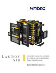
LANBOY User’s Manual
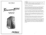
LANBOY - Aluminum Mini Tower Case
The LANBOY case comes with the Antec’s SmartBlue power supply with blue
LED illumination. SmartBlue comes with a main power switch. Make sure you
turn the switch to the ON ( I ) position before you boot up your computer for
the first time. In normal operation there is no need to turn the switch to the
OFF (O) position since the power supply is equipped with a soft on/off feature
which turns your computer on and off through the soft switch on your computer
case.You may need to turn the switch to the OFF position occasionally should
your computer crash and you cannot shut it down through use of the soft
switch.
Set Up
1. Take the case out of the box. Remove the Styrofoam. Remove the plastic bag.
2. Place the case upright with the power supply fan at the back facing you.
You will find an Expansion Slot Protective Cover mounted right above the
expansion slots. This cover has a compartment marked “hardware” to store
your hardware (screws, brass standoffs, plastic stands, etc).
3. Remove the screws from the right side panel. Grip the panel at the fingergrip indent and slide it towards you to open the case.
4. Inside the case you should see the power supply, some wiring with marked
connectors (USB, PWR etc.), an installed I/O panel and a power cord.
5. Press the tab on the Protective Cover to remove the cover for expansion
card installation
Motherboard Installation
This manual is not designed to cover CPU, RAM, or expansion card installation.
Please consult your motherboard manual for specific mounting instructions and
troubleshooting.
1. Lay the case down so that the open side is up. You should be able to see
the drive cage and power supply.
2. Make sure you have the appropriate I/O panel for your motherboard. If the
panel provided is not suitable for your motherboard, please contact your
motherboard manufacturer for the correct I/O panel.
3. Line up your motherboard with the standoff holes, and determine which
ones line up and remember where they are. Not all motherboards will match
with all of the provided screw holes and this is not necessary for proper
functionality. (In other words there will likely be extra holes.) Some standoffs
may be pre-installed for your convenience.
4. Lift up and remove your motherboard.
1
5. Screw in the brass standoffs to the threaded holes that line up with your
motherboard.
6. Place your motherboard on the brass standoffs.
7. Screw in your motherboard to the standoffs with the provided metallic
Phillips-head screws. Your motherboard is now installed.
Power/LED Connections
The Antec SmartBlue power supply is an ATX12V form factor power supply
with a single 20-pin Main Power Connector, a 6-pin AUX Power Connector,
and a 4-pin +12V Power Connector for the motherboard. It also comes with
five to seven 4-pin Peripheral Power Connectors and one to two 4-pin Floppy
Drive Power Connectors for your drives. It is backwards compatible to previous
ATX form factor power supplies. If your motherboard does not support the
AUX Power Connector or the +12V Power Connector, you can still use this
power supply.
The power supply is also equipped with a 3-pin fan signal connector. Connect
it to one of the fan connectors on your motherboard. You may monitor the
speed of the rear power supply fan through your motherboard BIOS or through
the monitoring software that comes with your motherboard. Note: The speed
of the fan may be as low as 1500 RPM when temperatures are low. At these
speeds some motherboards may not be able to properly detect the fan speed
and may generate false warnings of fan failure. Please refer to your motherboard manual for proper fan monitoring set up.
1. Connect the 20-pin ATX power connector (and AUX or +12V connectors
if appropriate) to your motherboard.
2. Reset switch (labeled RESET SW) connects to your motherboard at the RST
connector. The colored wire should be attached to Pin 1 and the black wire
to ground. This applies for all of the following connectors as well.
3. Power Switch (labeled POWER SW) connects to the PWR connector on the
4. The Power LED, Hard Drive LED, and Speaker connectors all share a
single ribbon cable. Attach the POWER LED, HDD LED connector and
SPEAKER connectors to the appropriate headers on your motherboard.
USB Connection
There are 8 wires with connectors coming out from the front mounted USB
ports of the case.
1. Locate the internal USB port on your motherboard. They consist of 10-pins
in two rows. Note: On some motherboards one or two pins may be marked
as NC. This indicates no contact. It is an empty pin. You don’t need to use
it. On some motherboards one pin may be missing on either one or both
rows. Don’t worry about it. You only need 8 pins to connect to.
2. Consult your motherboard manual to get each of the pin-out positions.
3. Power Pins: There are two power pins, one on each row. They are usually
marked as Power, Vcc or +5V. Connect the two +5V connectors to the
two power pins. Each connector can go to either pin.
4. Ground Pins: There are two ground pins, one on each row. They are usually
marked as GROUND or GND. Connect the two GROUND connectors to the
two ground pins. Each connector can go to either pin.
2