1
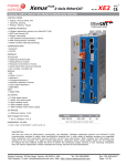
Xenus
PLUS

2-Axis CANopen
Rev 01
XP2
RoHS
digital servo drive for brush & brushless motors
Control Modes
• Indexer, Point-to-Point, PVT
• Camming, Gearing
• Position, Velocity, Torque
Command Interface
• CANopen
• ASCII and discrete I/O
• Stepper commands
• ±10V position/velocity/torque (2 inputs)
• PWM velocity/torque command
• Master encoder (Gearing/Camming)
Communications
• CANopen
• RS-232
Feedback
Incremental
•Digital quad A/B encoder
• Analog sin/cos encoder
• Panasonic Incremental A
• Aux. encoder / encoder out
Absolute
• SSI
•EnDat 2.1 & 2.2
• Absolute A
• Tamagawa Absolute A
• Panasonic Absolute A Format
• BiSS (B&C)
Other
•Digital Halls
I/O Digital
• 12 High-speed inputs
• 2 Motor over-temp inputs
• 8 Opto-isolated inputs
• 5 Opto-isolated outputs
• 2 Opto-isolated motor brake outputs
I/O Analog
• 2 Reference inputs, 14-bit
Safe Torque Off (STO)
• SIL 3, Category 3, PL d
Dimensions: in [mm]
Model
Vac
Ic
Ip
XP2-230-20
100~240
10
20
Add -R to model number for resolver option
• 9.24 [234.7] x 5.42 [137.6] x 3.59 [91.1]
description
XP2 sets new levels of performance, connectivity, and
flexibility. CANopen communication provides a widely used
cost-effective industrial bus. A wide range of absolute
encoders are supported.
Copley Controls, 20 Dan Road, Canton, MA 02021, USA
P/N 16-<tbd> Rev 00 September 23, 2015 High resolution A/D converters ensure optimal current loop
performance. Both isolated and high-speed non-isolated I/O are
provided. For safety critical applications, redundant power stage
enable inputs can be employed.
Tel: 781-828-8090
Fax: 781-828-6547
Page 1 of 36
Xenus
PLUS

2-Axis CANopen
Rev 01
XP2
RoHS
general specifications
Test conditions: Wye connected load: 2 mH line-line. Ambient temperature = 25° C. Power input = 230 Vac, 60 Hz, 1 Ø
MODEL
XP2-230-20
Output CURRENT (each axis)
Peak Current
20 (14)
Adc (Arms, sinusoidal)
Peak time
1
s
Continuous current (Note 1)
10 (7)
Adc (Arms, sinusoidal)
INPUT POWER
Mains voltage, phase, frequency
100~240
Vac, ±10%, 1 Ø or 3 Ø, 47~63 Hz
Mains current
20
Arms
+24 Vdc Control power
+20 to +32 Vdc, 500 mA max
Required for operation
DIGITAL CONTROL
Digital Control Loops
Current, velocity, position. 100% digital loop control
Sampling rate (time)
Current loop: 16 kHz (62.5 µs), Velocity & position loops: 4 kHz (250 µs)
Bus voltage compensation
Changes in bus or mains voltage do not affect bandwidth
Minimum load inductance
200 µH line-line
command inputs (Note: Digital input functions are programmable)
Distributed Control Modes
CANopen
Position, Velocity, Torque (Profile & Interpolated modes), Homing
Stand-alone mode
Analog torque, velocity, position reference
±10 Vdc, 14 bit resolutionDedicated differential analog input
Digital position reference
Pulse/Direction, CW/CCW
Stepper commands (2 MHz maximum rate)
Quad A/B Encoder
2 M line/sec, 8 Mcount/sec (after quadrature)
Digital torque & velocity reference
PWM , Polarity
PWM = 0% - 100%, Polarity = 1/0
PWM 50%
PWM = 50% ±50%, no polarity signal required
PWM frequency range
1 kHz minimum, 100 kHz maximum
PWM minimum pulse width
220 ns
IndexingUp to 32 sequences can be launched from inputs or ASCII commands.
CammingUp to 10 CAM tables can be stored in flash memory
ASCII
RS-232, 9600~115,200 Baud, 3-wire, RJ-12 connector
DIGITAL inputs
Number22
[IN1,11]Digital, Schmitt trigger, 1 µs RC filter, 24 Vdc compatible, programmable pull-up/down to +5 Vdc/ground,
Vt+ = 2.5~3.5 Vdc, VT- = 1.3~2.2 Vdc, VH = 0.7~1.5 Vdc
[IN21, 22]
Same specs as IN1 & IN11, but with fixed pull-up to +5 Vdc
[IN2~5,12~15]
Programmable as single-ended or differential pairs, 100 ns RC filter, 12 Vdc max,
10 kΩ programmable pull-up/down per input to +5 Vdc/ground,
SE: Vin-LO ≤ 2.3 Vdc, Vin-HI ≥ 2.7 Vdc, VH = 45 mV typ, DIFF: Vin-LO ≤ 200 mVdc, Vin-HI ≥ 200 mVdc, VH = 45 mV typ,
[IN6~9,16~19]
Opto-isolated, single-ended, ±15~30 Vdc compatible, bi-polar, 2 groups of 4 with common return for each group
Rated impulse ≥ 800 V, Vin-LO ≤ 6.0 Vdc, Vin-HI ≥ 10.0 Vdc, Input current ±3.6 mA @ ±24 Vdc, typical
[IN10,20]
Motor overtemp signals on feedback connectors, , Schmitt trigger, 24 Vdc compatible
330 µs RC filter, 4.99k pullup to +5 Vdc, Vt+ = 2.5~3.5 Vdc, VT- = 1.3~2.2 Vdc, VH = 0.7~1.5 Vdc
analog inputs
Number
4
[AIN1~2]Differential, ±10 Vdc, 5 kW input impedance, 14-bit resolution
[AIN3~4]
Single-ended, motor temperature sensor, 4.99 kW pulled-up to +5 Vdc, 12-bit resolution
safe torque off (sto)
Function
PWM outputs are inactive and current to the motor will not be possible when the STO function is asserted
Standard
Designed to IEC-61508-1, IEC-61508-2, IEC-61800-5-2, ISO-13849-1
Safety Integrity Level
SIL 3, Category 3, Performance level d
Inputs
2 two-terminal: STO-IN1+,STO-IN1-, STO-IN2+, STO-IN2Type
Opto-isolators, 24V compatible, Vin-LO ≤ 6.0 Vdc or open, Vin-HI ≥ 15.0 Vdc,
Input current (typical) STO-IN1: 9.0 mA, STO-IN2: 4.5 mA
Response time
2 ms from Vin ≤6.0 Vdc to interruption of energy supplied to motor
Reference
Complete information and specifications are in the Xenus Plus 2-Axis STO Manual
digital outputs
Number
[OUT1~5]
[OUT6~7]
RS-232 PORT
Signals
Mode
Protocol
CAN PORT
Signals
Format
Data
Address selection
status indicator LEDs
Drive Status
CAN Status
5V output
Number
Ratings (each)
7
Opto-isolated Darlingtons, 20 mA max, 24 V tolerant, collector & emitter connections
Motor brake control: opto-isolated, current-sinking with flyback diode to +24 Vdc, 1 Adc max
RxD, TxD, Gnd in 6-position, 4-contact RJ-12 style modular connector
Full-duplex, DTE serial communication port for drive setup and control, 9,600 to 115,200 baud
Binary and ASCII formats
CANH, CANL, Gnd in 8-position dual RJ-45 style modular connector, wired as per CAN Cia DR-303-1, V1.1
CAN V2.0b physical layer for high-speed connections compliant
CANopen Device Profile DSP-402
16 position rotary switch on front panel with 3 additional address bits available as
digital inputs or programmable to flash memory (7-bit addressing, 127 nodes per CAN network)
Bicolor LED, drive status indicated by color, and blinking or non-blinking condition
Bicolor LED, status of CAN bus indicated by color and blink codes to CAN Indicator Specification 303-3
4, two on the feedback connectors (J10, J11), two on the control connector (J12) for the A and B multi-mode ports
+5 Vdc @ 500 mA, thermal and overload protected
Copley Controls, 20 Dan Road, Canton, MA 02021, USA
P/N 16-<tbd> Rev 00 September 23, 2015 Tel: 781-828-8090
Fax: 781-828-6547
Page 2 of 36
Xenus
PLUS

2-Axis CANopen
Rev 01
XP2
RoHS
general specifications
REGENERATION
Operation
Cut-In Voltage
Drop-Out Voltage
Tolerance
Internal solid-state switch drives external regen resistor (see Ordering Guide for types)
+HV > 390 Vdc
Regen output is on, (optional external) regen resistor is dissipating energy
+HV < 380 Vdc
Regen output is off, (optional external) regen resistor not dissipating energy
±2 Vdc
For either Cut-In or Drop-Out voltage
protections
HV Overvoltage
HV Undervoltage
Drive over temperature
Short circuits
I2T Current limiting
Motor over temperature
Feedback power loss
+HV > 400 VdcDrive PWM outputs turn off until +HV is less than overvoltage
+HV < 60 VdcDrive PWM outputs turn off until +HV is greater than undervoltage
IGBT > 80 °C ±3 °CDrive PWM outputs turn off until IGBT temperature is below threshold
Output to output, output to ground, internal PWM bridge faults
Programmable: continuous current, peak current, peak time
Programmable input to disable drive when voltage is above or below a set point 0~5 Vdc
Fault occurs if feedback is removed or +5 V is <85% of normal
MECHANICAL & ENVIRONMENTAL
Size
9.24 x 5.42 x 3.59 [234.7 x 137.6 x 91.1] in[mm]
Weight
4.19 lb [1.90kg]
Ambient temperature
0 to +40 °C operating, -40 to +85 °C storage
Humidity
0% to 95%, non-condensing
Contaminants
Pollution degree 2
Vibration
2 g peak, 10~500 Hz (sine), IEC60068-2-6
Shock
10 g, 10 ms, half-sine pulse, IEC60068-2-27
EnvironmentIEC68-2: 1990
OPTIONS
XTL-FA-01 Edge Filter
One used for each motor output. A passive R-L-C filter that reduces capacitive coupling of PWM outputs
to adjacent cabling by lengthening the rise/fall times and providing common-mode filtering of the
PWM outputs. Typically used in systems that have servo drives operating near other cables
carrying low-amplitude sensor or video signals.
Further details on the XTL-RA-04 can be found in the Xenus Regeneration Guide on the Copley Controls web-site
http://www.copleycontrols.com/Motion/pdf/Xenus_regen_guide-03-04.pdf
XTL-RA-04 Regen Resistor
Used when the regenerative energy from a moving load is greater than the absorption
capacity of the internal regen resistor. 15 W, 65 W default continuous power, 400 W max continuous power
10 kW peak power, 1000 ms peak power time.
Further details on the XTL-FA-01 can be found in the XTL-FA-01 Edge Filter for Xenus User Guide on the
Copley Controls web-site: http://www.copleycontrols.com/Motion/pdf/Xenus-Filter.pdf
agency standards conformance
Standards and Directives
Functional Safety
IEC 61508-1:2010, IEC 61508-2:2010, IEC 61508-3:2010, IEC 61508-4: 2010 (SIL 3)
Directive 2006/42/EC (Machinery)
ISO 13849-1/Cor. 1:2009 (Cat 3, PL d)
IEC 61800-5-2:2007 (SIL3)
(see the Xenus Plus Dual Axis STO Manual for further details)
Product Safety
Directive 2006/95/EC (Low Voltage)
IEC 61800-5-1:2007
EMC
Directive 2004/108/EC (EMC)
IEC 61800-3:2004/A1:2011
RoHS
Restriction of the Use of Certain Hazardous Substances (RoHS)
Directive 2011/65/EU (RoHS II)
Approvals
UL and cUL recognized component to:
UL 61800-5-1, 1st Ed.
TÜV SÜD Functional Safety to:
IEC 61508-1:2010, IEC 61508-2:2010, IEC 61508-3:2010, IEC 61508-4: 2010 (SIL 3)
ISO 13849-1/Cor. 1:2009 (Cat 3, PL d)
Copley Controls, 20 Dan Road, Canton, MA 02021, USA
P/N 16-<tbd> Rev 00 September 23, 2015 Tel: 781-828-8090
Fax: 781-828-6547
Page 3 of 36
Xenus
PLUS

2-Axis CANopen
Rev 01
XP2
RoHS
feedback: XP2-230-20
feedback
Incremental:
Digital Incremental Encoder Quadrature signals, (A, /A, B, /B, X, /X), differential (X, /X Index signals not required)
5 MHz maximum line frequency (20 M counts/sec)
MAX3097 differential line receiver with 121 Ω terminating resistor between complementary inputs
Analog Incremental Encoder
Sin/cos format (sin+, sin-, cos+, cos-), differential, 1 Vpeak-peak,
ServoTube motor compatible, BW > 300 kHz, 121 Ω terminating resistor between complementary inputs
Analog Index signalDifferential, 121 Ω terminating resistor between complementary inputs, 1 Vpeak-peak zero-crossing detect
Panasonic Incremental A Format
Sanyo Denki Wire-saving Incremental
Absolute:
SSI
Clock (X, /X), Data (S, /S) signals, 4-wire, clock output from XP2, data returned from encoder
EnDAT
Clock (X, /X), Data (S, /S), sin/cos (sin+, sin-, cos+, cos-) signals
Absolute A, Tamagawa Absolute A, Panasonic Absolute A Format, Sanyo Denki Absolute A
SD+, SD- (S, /S) signals, 2.5 or 4 MHz, 2-wire half-duplex communication
Position feedback: 13-bit resolution per rev, 16 bit revolution counter (29 bit absolute position data)
Status data for encoder operating conditions and errors
BiSS (B&C)
MA+, MA- (X, /X), SL+, SL- (S, /S) signals, 4-wire, clock output from XP2, data returned from encoder
Digital Halls
Type Digital, single-ended, 120° electrical phase difference between U-V-W signals,
Schmitt trigger, 1 µs RC filter, 24 Vdc compatible, programmable pull-up/down to +5 Vdc/ground,
Vt+ = 2.5~3.5 Vdc, VT- = 1.3~2.2 Vdc, VH = 0.7~1.5 Vdc
Inputs
10 kW pullups to +5 Vdc, 1 µs RC filter to Schmitt trigger inverters
multi-mode encoder port
As InputDigital quadrature encoder (A, /A, B, /B, X, /X), 121 Ω terminating resistors between A & /A, B & /B inputs
18 M-counts/sec, post-quadrature (4.5 M-lines/sec)
Digital absolute encoder (Clk, /Clk, Dat, /Dat) half or full-duplex operation, 121 Ω terminating resistors
As Emulated OutputQuadrature encoder emulation with programmable resolution to 4096 lines (65,536 counts) per rev
from analog sin/cos encoders
A, /A, B, /B, outputs from MAX3032 differential line driver, X, /X, S, /S outputs from MAC3362 drivers
As Buffered OutputDigital encoder feedback signals from primary digital encoder are buffered by MAX3032 line driver
ENCODER Power Supplies
Number
Ratings
4, two on the feedback connectors (J10, J11), two on the control connector (J12)
for the A and B multi-mode ports
+5 Vdc @ 500 mA, thermal and overload protected, each output. 2000 mA total for all four outputs)
feedback: XP2-230-20-R
Resolver
Type Brushless, single-speed, 1:1 to 2:1 programmable transformation ratio
Resolution
14 bits (equivalent to a 4096 line quadrature encoder)
Reference frequency
8.0 kHz
Reference voltage
2.8 Vrms, auto-adjustable by the drive to maximize feedback
Reference maximum current 100 mA
Maximum RPM
10,000+
Sin/Cos inputsDifferential, 54k ±1% differential impedance, 2.0 Vrms, BW ≥ 300 kHz
Digital Halls
Type Digital, single-ended, 120° electrical phase difference between U-V-W signals,
Schmitt trigger, 1 µs RC filter, 24 Vdc compatible, programmable pull-up/down to +5 Vdc/ground,
Vt+ = 2.5~3.5 Vdc, VT- = 1.3~2.2 Vdc, VH = 0.7~1.5 Vdc
Inputs
10 kW pullups to +5 Vdc, 1 µs RC filter to Schmitt trigger inverters
multi-mode encoder port
As InputDigital quadrature encoder (A, /A, B, /B, X, /X), 121 Ω terminating resistors between A & /A, B & /B inputs
18 M-counts/sec, post-quadrature (4.5 M-lines/sec)
Digital absolute encoder (Clk, /Clk, Dat, /Dat) half or full-duplex operation, 121 Ω terminating resistors
(See above for listing of absolute encoder types. EnDat Sin/Cos signals are not supported)
As Emulated OutputQuadrature encoder emulation with programmable resolution to 4096 lines (65,536 counts) per rev from
resolver, A, /A, B, /B, outputs from MAX3032 differential line driver, X, /X, S, /S outputs from MAC3362 drivers
ENCODER Power Supplies
Number
Ratings
4, two on the feedback connectors (J10, J11), two on the control connector (J12)
for the A and B multi-mode ports
+5 Vdc @ 500 mA, thermal and overload protected, each output. 2000 mA total for all four outputs)
Copley Controls, 20 Dan Road, Canton, MA 02021, USA
P/N 16-<tbd> Rev 00 September 23, 2015 Tel: 781-828-8090
Fax: 781-828-6547
Page 4 of 36
Xenus
PLUS

2-Axis CANopen
Rev 01
XP2
RoHS
canopen communications
Xenus uses the CAN physical layer signals CANH, CANL, and GND for connection, and CANopen protocol for communication.
Before installing the drive in a CAN system, it must be assigned a CAN address. A maximum of 127 CAN nodes are allowed on a single
CAN bus. The rotary switch on the front panel controls the four lower bits of the seven-bit CAN address. When the number of nodes on
a bus is less than sixteen, the CAN address can be set using only the switch.
For installations with sixteen or more CAN nodes on a network CME 2 can be used to configure Xenus to use the rotary switch,
or combinations of digital inputs and programmed offset in flash memory to configure the drive with a higher CAN node address.
For more information on CANopen communications, download the CANopen Manual from the Copley web-site:
http://www.copleycontrols.com/motion/downloads/pdf/CANopenProgrammersManual.pdf
canopen connectors
Dual RJ-45 connectors that accept standard Ethernet
cables are provided for CAN bus connectivity. Pins
are wired-through so that drives can be daisychained and controlled with a single connection
to the user’s CAN interface. A CAN terminator
should be placed in the last drive in the chain.
The XP2-NK connector kit provides a D-Sub adapter
that plugs into a CAN controller and has an RJ-45
socket that accepts the Ethernet cable.
XP2-NK can connector kit
The kit contains the XP2-CV adapter that converts the CAN interface D-Sub
9M connector to an RJ-45 Ethernet cable socket, plus a 10 ft (3 m) cable and
terminator. Both connector pin-outs conform to the CiA DR-303-1 specification.
1
6
8
J7
RJ-45
D-Sub 9F
CAN_L
Pin 1
1
9
5
CAN_GND
Pin 8
CAN_H
2
2
3
3
7
1
CAN_L
CAN_GND
CAN_H
CAN Status LED
J7
J7 CAN connections
CAN status LED
NET (CAN status) LED
A bi-color LED gives the state of the CAN connection in
accordance with the CAN-CiA specification 303, part 3.
The green (RUN) LED shows the state of the CANopen state
machine. The red (ERR) LED shows the occurrence of errors
(sync, guard, or heartbeat) and of the CAN bus physical
layer.
During a reset condition, the green LED will be off.
In operation, the red & green colors will alternate with the
number of blinks or on/off condition shown in the table to
the right.
Note: Red & green led on-times do not
overlap. LED color may be red, green, off,
or flashing of either color.
Note: Red & green led on-times do not overlap.
LED color may be red, green, off, or flashing of either color.
can network node-id (address)
In an CANopen network, nodes are assigned addresses 1~127. Address 0 is reserved for the CAN bus
master. In the XPL, the node address is provided by two 16-position rotary switches with hexadecimal
encoding. These can set the address of the drive from 0x01~0x7F (1~127 decimal). The chart shows the
decimal values of the hex settings of each switch.
DEVICE ID
X10
X1
x1
S2
S1
x16
Node-ID (Address) Switches
To find the Node-ID given the switch settings:
Node-ID = (S1 * 16) + S2
Example: S1 = 5, S2 = B
S1 value = (5*16) = 80, S2 value = Hex(B) = 11,
Node-ID = 80 + 11 = 91
To find the switch settings for a given address:
S1 = The integer part of (Node-ID / 16)
S2 = Hex (Node-ID - (S1 * 16) )
Example: Node-ID = 91
S1 = 91/16 = 5.69, integer part = 5, (5*16) = 80
S2 = Hex (91 - 80) = 11 = 0xB
S1
Hex
0
0
0
1
16
1
2
32
2
3
48
3
4
64
4
5
80
5
6
96
6
7
112
7
Copley Controls, 20 Dan Road, Canton, MA 02021, USA
P/N 16-<tbd> Rev 00 September 23, 2015 Tel: 781-828-8090
8
8
9
9
A
10
B
C
D
CME2 -> Amplifier -> Network Configuration
S2
Dec
Not
Used
for
CAN
Addr
11
12
13
E
14
F
15
Fax: 781-828-6547
Page 5 of 36
Xenus
PLUS

2-Axis CANopen
Rev 01
XP2
RoHS
communications: rs-232 serial
XP2 is configured via a three-wire, full-duplex DTE RS-232 port that operates from 9600 to 115,200 Baud, 8 bits, no parity, and one stop bit. Signal format
is full-duplex, 3-wire, DTE using RxD, TxD, and Gnd. Connections to the XP2 RS-232 port are through J7, an RJ-11 connector. The XP2 Serial Cable Kit
(SER-CK) contains a modular cable, and an adapter that connects to a 9-pin, Sub-D serial port connector (COM1, COM2, etc.) on PC’s and compatibles.
SER-CK serial cable kit
J6: RS-232 Port
The SER-CK provides connectivity between a D-Sub 9 male connector and the RJ-11
connector on the XP2. It includes an adapter that plugs into the COM1 (or other)
port of a PC and uses common modular cable to connect to the XP2. The connections
are shown in the diagram below.
1
5
Dsub-9F
to RJ11
Adapter
6
9
6
RJ-11 cable
6P6C
Straight-wired
D-Sub 9F
RxD
TxD
Gnd
2
5
3
2
5
3
TxD
RJ-11 receptacle,
6 position, 4 contact
Pin
signal
2
RxD
3,4
Gnd
5
Txd
1
RJ-11
on
Servo
Drive
Don’t forget to order a Serial Cable Kit SER-CK when
placing your order for an XP2!
RxD
Gnd
ascii communication protocol
ASCII communications
The Copley ASCII Interface is a set of ASCII format commands that can be used to operate and monitor Copley Controls Accelnet,
Stepnet, and Xenus series amplifiers over an RS-232 serial connection. For instance, after basic amplifier configuration values have
been programmed using CME 2, a control program can use the ASCII Interface to:
• Enable the amplifier in Programmed Position mode.
• Home the axis.
• Issue a series of move commands while monitoring position, velocity, and other run-time
variables.
Additional information can be found in the ASCII Programmers Guide on the Copley website:
http://www.copleycontrols.com/Motion/pdf/ASCII_ProgrammersGuide.pdf
RS-232 multi-drop
The RS-232 specification makes no allowance for more than two devices on a serial link. But, multiple Xenus drives can communicate
over a single RS-232 port by daisy-chaining a master drive to other drives using CAN cables. In the CAN protocol, address 0 is reserved
for the CAN master and thereafter all other nodes on a CAN network must have unique, non-zero addresses. When the Xenus CAN
address is set to 0, it acts as a CAN master, converting the RS-232 data into CAN messages and passing it along to the other drives
which act as CAN nodes.
RS-232
CANopen
CAN Addr 0
CAN Master
CANopen
CAN Addr 1
CAN Node
CAN Addr n
CAN Node
For Serial-multi-drop you’ll need an Serial Cable Kit SER-CK plus CANopen network cables to connect the drives as shown.
The XP2-NC-01 and XP2-NC-10 are 1 ft (0.3m) and 10 ft (3m) cables that will do the job.
Copley Controls, 20 Dan Road, Canton, MA 02021, USA
Tel: 781-828-8090
P/N
Rev 00
September 23, 2015 Web: http://www.copleycontrols.com
Tech16-<tbd>
Support: E-mail:
[email protected],
Fax: 781-828-6547
6 of 36
Page Page
6 of 36
Xenus
PLUS

2-Axis CANopen
Rev 01
XP2
RoHS
safe torque off (sto)
description
The XP2 provides the Safe Torque Off (STO) function as defined in IEC 61800-5-2. Three opto-couplers are provided which, when de-energized, prevent
the upper and lower devices in the PWM outputs from being operated by the digital control core. This provides a positive OFF capability that cannot be
overridden by the control firmware, or associated hardware components. When the opto-couplers are activated (current is flowing in the input diodes),
the control core will be able to control the on/off state of the PWM outputs.
installation
Refer to the Xenus Plus Dual-Axis STO User Manual
DANGER
The information provided in the Xenus Plus Dual-Axis STO User Manual must be
considered for any application using the XP2 drive’s STO feature.
Failure to heed this warning can cause equipment damage, injury, or death.
sto bypass (muting)
In order for the PWM outputs of the XP2 to be activated, current must be flowing through all of the opto-couplers that are connected to the STO-1 and
STO-2 terminals of J6, and the drive must be in an ENABLED state. When the opto-couplers are OFF, the drive is in a Safe Torque Off (STO) state and
the PWM outputs cannot be activated by the control core to drive a motor. This diagram shows connections that will energize all of the opto-couplers
from an internal current-source. When this is done the STO feature is overridden and control of the output PWM stage is under control of the digital
control core.
If not using the STO feature, these connections must be made in order for the XP2 to be enabled.
sto bypass connections
V_in
Xenus Plus Dual-Axis
PWM Signals
1
6
Note: STO applies to
Axis-A AND Axis-B
Bypass Plug Connections
Jumper pins:
2-4, 3-5, 6-8, 7-9 *
EN
J6
Voltage
Regulator
+VI
Buffer
9
5
+VI
Current must flow
through all of the
opto-couplers before
the XP2
can be enabled
2
3
* STO bypass connections on the XP2 and Xenus
XPL models are different. If both drives are
installed in the same cabinet, the diode should
be wired as shown to prevent damage that could
occur if the STO bypass connectors are installed
on the wrong drive. The diode is not required for
STO bypass on the XP2 and can be replaced by a
wire between pins 7 and 9.
4
5
6
7
*
8
9
1
safety connector J6
Upper IGBT Gate Drive
STO-1(+)
+HV
STO-1(-)
PWM
Outputs
STO-2(+)
STO-2(-)
STO-1(+)
+VI
Lower IGBT Gate Drive
STO-1(-)
STO-24V
STO-GND
Frame Ground
* XE2 and XEL-XPL STO bypass connections are different.
The diode shown should be used if XE2 and XEL-XPL drives are used on the
same equipment. Otherwise, the diode may be replaced by a jumper.
XE2 STO bypass connectors are not compatible with XEL-XPL drives.
J6 signals
SAFETY
Pin
Signal
Pin
Signal
1
Frame Gnd
6
STO-1(+)
2
STO-1(+)
7
STO-1(-)
1
6
9
5
3
STO-1(-)
8
STO-24V
4
STO-2(+)
9
STO-GND
5
STO-2(-)
Copley Controls, 20 Dan Road, Canton, MA 02021, USA
P/N 16-<tbd> Rev 00 September 23, 2015 Tel: 781-828-8090
Fax: 781-828-6547
Page 7 of 36
Xenus
PLUS

2-Axis CANopen
Rev 01
XP2
RoHS
high speed inputs: in2, in3, IN4, in5, in12, in13, in14, in15
DIGITAL position
Digital position commands can be in either single-ended or differential format. Single-ended signals should be sourced from devices with active pull-up
and pull-down to take advantage of the high-speed inputs. Differential inputs have 121 W line-terminators.
Single-ended pulse & Direction
IN4(14)
differential pulse & Direction
IN2(12)
Pulse
PULSE+
IN3(13)
IN5(15)
PULSE-
Direction
IN4(14)
IN5(15)
Single-ended CU/CD
command single-ended
Signal
Axis A
Axis B
Pls, Enc A
J12-10
J12-15
Dir, Enc B
J12-11
J12-30
DIRECTION+
Sgnd
J12-6,16,22,31,37,44
DIRECTION-
Shld
J12-1
differential CU/CD
CU (Count-Up)
CU (Count-Up)
IN4(14)
IN5(15)
IN2(12)
IN3(13)
CU
CD
CD (Count-Down)
CD (Count-Down)
IN4(14)
IN5(15)
QUAD a/b ENCODER SINGLE-ENDED
Encoder ph. A
IN5(15)
command differential
PULSE-
DIRECTION+
DIRECTION-
QUAD a/b ENCODER DIFFERENTIAL
Encoder ph. A
IN4(14)
PULSE+
Enc. A
Enc. B
Encoder ph. B
Encoder ph. B
IN2(12)
Enc. A
IN3(13)
Enc. /A
IN4(14)
Enc B
IN5(15)
Enc /B
Signal
Axis A
Axis B
Pls, Enc A
J12-8
J12-13
/Pls, Enc /A
J12-9
J12-14
Dir, Enc B
J12-10
J12-15
/Dir, Enc /B
J12-11
J12-30
Sgnd
J12-6,16,22,31,37,44
Shld
J12-1
DIGITAL TORQUE, VELOCITY
Digital torque or velocity commands can be in either single-ended or differential format. Single-ended signals must be sourced from devices with active
pull-up and pull-down to take advantage of the high-speed inputs.
Single-ended PWM & Direction
Duty = 0~100%
differential PWM & Direction
IN4(14) Current or
Velocity
Duty = 0 - 100%
IN2(12)
IN3(13)
PWM+
PWM-
IN5(15) Polarity or
Direction
IN4(14)
IN5(15)
Single-ended 50% PWM
Duty = 50% ±50%
<no connection>
IN5(15)
Duty = 50% ±50%
IN2(12)
No function
Axis B
J12-10
J12-15
J12-11
J12-30
Dir
Sgnd
J12-6,16,22,31,37,44
Direction-
Shld
J12-1
Curr/Vel+
Curr/Vel-
IN4(14)
Copley Controls, 20 Dan Road, Canton, MA 02021, USA
P/N 16-<tbd> Rev 00 September 23, 2015 Axis A
PWM
command differential
IN3(13)
<no connection>
Signal
Direction+
differential 50% PWM
IN4(14) Current or
Velocity
command single-ended
IN5(15)
No
Function
Tel: 781-828-8090
Signal
Axis A
Axis B
PWM
J12-8
J12-13
/PWM
J12-9
J12-14
Dir
J12-10
J12-15
/Dir
J12-11
J12-30
Sgnd
J12-6,16,22,31,37,44
Shld
J12-1
Fax: 781-828-6547
Page 8 of 36
Xenus
PLUS

2-Axis CANopen
XP2
Rev 01
RoHS
Multi-mode encoder port as an input
input types
command input
multi-port
POSITION COMMAND INPUTS: DIFFERENTIAL
• Pulse & Direction
• CW & CCW (Clockwise & Counter-Clockwise)
• Encoder Quad A & B
• Camming Encoder A & B input
MAX3097
Input/Output
Select
A/B/X signals from
digital encoder
MAX3097
Input/Output
Select
Pulse/Dir or CU/CD
differential commands
Axis A
Axis B
J12-36
J12-42
/Pls, Enc /A
J12-21
J12-27
Dir, Enc B
J12-35
J12-41
/Dir, Enc /B
J12-20
J12-26
Enc X
J12-34
J12-40
J12-19
J12-25
Enc /X
MAX3032
CURRENT or VELOCITY COMMAND INPUTS: DIFFERENTIAL
• Current or Velocity & Direction
• Current or Velocity (+) & Current or Velocity (-)
Signal
Pls, Enc A
Sgnd
J12-6,16,22,31,37,44
Shld
J12-1
J12 Multi-Port
Frame Ground
A
Enc. A
/A
Incremental
Encoder
B
Enc. B
/B
MAX3032
X
Enc. X
/X
SECONDARY FEEDBACK: INCREMENTAL
• Quad A/B/X incremental encoder
• Quad A/B emulated encoder from sin/cos encoder
Enc. X
Enc. X
MAX3097
Input/Output
Select
A/B/X signals from
digital encoder
Absolute
Encoder
S
Enc. S
/S
MAX3032
Enc. S
+5V output @ 500 mA
Signal Ground
SECONDARY FEEDBACK: ABSOLUTE
• S channel: Absolute A encoders (2-wire)
The S channel first sends a Clock signal and then
receives Data from the encoder in half-duplex mode.
• S & X channels: SSI, BiSS, EnDat encoders (4-wire)
The X channel sends the Clock signal to the encoder,
which initiates data transmission from the encoder
on the S-channel in full-duplex mode
emulated quad a/b/x
multi-port
S
Input/Output
Select
2-Wire digital absolute
encoder signals
Signal
Axis A
Axis B
Enc A
J12-36
J12-42
Enc /A
J12-21
J12-27
Enc B
J12-35
J12-41
Enc /B
J12-20
J12-26
Enc X
J12-34
J12-40
J12-19
J12-25
Enc /X
MAX3032
S
Copley Controls, 20 Dan Road, Canton, MA 02021, USA
P/N 16-<tbd> Rev 00 September 23, 2015 Tel: 781-828-8090
Sgnd
J12-6,16,22,31,37,44
Shld
J12-1
Fax: 781-828-6547
Page 9 of 36
Xenus
PLUS

2-Axis CANopen
Rev 01
general purpose inputs
Input
HS Inputs [IN1~2]
24 Vdc max
+5.0 V
A
74HC14
10k
[IN1]
[IN2]
[IN15]
10k
100p
Vmax
+5V
±10
+12V
Pin
R1
R2
C1
Vm
Input
Pin
R1
R2
C1
Vm
10k
10k
100p
+24
*IN11
J12-12
10k
10k
100p
+24
10k
1k
100p
+12
*IN1
J12-7
*IN2
J12-8
*IN12
J12-13
*IN3
J12-9
*IN13
J12-14
*IN4
J12-10
*IN14
J12-15
*IN5
J12-11
*IN15
J12-30
IN6
J9-2
IN16
J9-7
IN7
J9-3
IN17
J9-8
IN8
J9-4
IN18
J9-9
IN9
J9-5
IN19
J9-18
ICOM1
J9-6
ICOM2
J9-17
10k
1k
100p
Opto
IN10
J10-7
4.99k
10k
33n
±24V
IN21
J10-24
10k
10k
100p
The input resistor of these inputs is programmable to pull-up to
+5V or pull-down to 0V. Pull-up is the default and works with
current-sinking outputs from a controller. Pull-down works with
current-sourcing outputs, typically PLC’s that drive grounded loads.
Six of the inputs have individually settable PU/PD.
The other four have PU/PD control for pairs of inputs.
+5V PullUp = 5V
PullDown = 0V
±24
IN20
J11-7
4.99k
10k
33n
IN22
J11-24
10k
10k
100p
+24
Input
Pin
PU/PD
Input
Pin
PU/PD
IN1
J12-7
1
IN11
J12-12
5
IN2
J12-8
2
IN12
J12-13
6
IN3
J12-9
3
IN13
J12-14
7
IN4
J12-10
IN14
J12-15
IN5
J12-11
IN15
J12-30
4
8
74HC14
[in2~5,12~15] Signals
10k
100p
Single-ended/Differential digital INPUTS [IN2~5,12~15]
These inputs have all the programmable functions of the GP inputs plus these
additional functions which can be configured as single-ended (SE)
or differential (DIFF):
• PWM 50%, PWM & Direction for Velocity or Current modes
• Pulse/Direction, CU/CD, or A/B Quad encoder inputs for Position
or Camming modes
single-ended
12 Vdc max
S.E.
Diff
Input
Input
IN2
IN2+
IN3
IN2-
IN4
IN4+
IN5
IN4-
S.E.
Diff
Input
Input
J12-8
IN12
IN12+
J12-13
J12-9
IN13
IN12-
J12-14
J12-10
IN14
IN14+
J12-15
J12-11
IN15
IN14-
J12-30
Pin
Pin
differential
12 Vdc max
12V
+5V
10k
1k
J12 Control
+5V
+
J12 Control
+
12V
+24
Opto
inputs with programmable pull up/Down
* programmable pull up/down
[INx]
+12
±24
+24V
10k
XP2
RoHS
MAX3096
10k
1k
MAX3096
[IN2,4,12,14]
[IN2,4,12,14]
100 pF
100 pF
2.5V
+5V
10k
10k
1k
1k
[IN3,5,13,15]
[IN3,5,13,15]
100 pF
+5V
+
MAX3096
100 pF
PLC outputs are frequently current-sourcing from 24V for driving grounded loads. PC based digital controllers
commonly use NPN or current-sinking outputs. Set the Xenus inputs to pull-down to ground for current-sourcing
connections, and to pull-up to 5V for current-sinking connections.
Copley Controls, 20 Dan Road, Canton, MA 02021, USA
P/N 16-<tbd> Rev 00 September 23, 2015 Tel: 781-828-8090
Fax: 781-828-6547
Page 10 of 36
Xenus
PLUS

2-Axis CANopen
Rev 01
XP2
RoHS
opto-isolated inputs: IN6, IN7, IN8, IN9, IN16, IN17, IN18, IN19
These inputs have all the programmable functions of the GP inputs plus opto-isolation. There are two groups of four inputs, each with
its’ own common terminal. Grounding the common terminal configures the inputs to work with current-sourcing outputs from controllers
like PLC’s. When the common terminal is connected to +24V, then the inputs will be activated by current-sinking devices such as NPN
transistors or N-channel MOSFETs. The minimum ON threshold of the inputs is ±15 Vdc.
In the graphics below, “24V” is for connections to current-sourcing outputs and
“GND” is for current-sinking outputs on the control system
[IN6~9]
[IN16~19]
±30 Vdc max
24V
±30 Vdc max
J9
GND
24V
+
[COMM1]
[IN6]
4.99k
[IN7]
3
4.99k
[IN8]
4
4.99k
[IN9]
+
5
4.99k
J9
GND
24V
+
6
2
24V
24V
[COMM2]
17
4.7k
4.99k
5.1V
4.7k
5.1V
4.7k
[IN16]
7
±30Vmax
±24V typical
4.7k
[IN17]
8
4.99k
+24V
4.7k
5.1V
4.7k
[IN18]
9
4.99k
5.1V
4.7k
5.1V
5.1V
5.1V
4.7k
[IN19]
18
+
24V
4.99k
5.1V
[in6~9,16~19] Signals
These inputs work with current-sourcing OR current-sinking
connections. Connect the COMM to controller ground/common
for current-sourcing connections and to 15~24V from the
controller for current-sinking connections.
Copley Controls, 20 Dan Road, Canton, MA 02021, USA
P/N 16-<tbd> Rev 00 September 23, 2015 Signal
Pins
Signal
Pins
IN6
J9-2
IN16
J9-7
IN7
J9-3
IN17
J9-8
IN8
J9-4
IN18
J9-9
IN9
J9-5
IN19
J9-18
COMM1
J9-6
COMM2
J9-17
Tel: 781-828-8090
Fax: 781-828-6547
Page 11 of 36
Xenus
PLUS

2-Axis CANopen
Rev 01
XP2
RoHS
analog inputs
The analog inputs have a ±10 Vdc range at 14-bit resolution
As reference inputs they can take position/velocity/torque commands
from a controller. If not used as command inputs, they can be used as
general-purpose analog inputs.
J12
D/A
[AINF.G.
A,B]
1 Frame Ground
3
±10V
[AIN A,B] Signals
2
Signal
Axis A
Axis B
AIN(+)
J12-3
J12-5
AIN(-)
J12-2
J12-4
Sgnd
J12-6,16,22,31,37,44
Shield
J12-1
AIN1+
-
Vref
AIN1-
+
1.5V
5
±10V
4
6
AIN2+
-
Vref
AIN2-
+
1.5V
Sgnd
isolated general purpose outputs out1~5
•
•
•
•
•
Digital, opto-isolated
SSR, 2-terminal
Flyback diode for inductive loads
24V Compatible
Programmable functions
[out1~5] Signals
Signal
Pins
Signal
Pins
[OUT1+]
J9-19
[OUT1-]
J9-10
[OUT2+]
J9-20
[OUT2-]
J9-11
[OUT3+]
J9-21
[OUT3-]
J9-12
[OUT4+]
J9-22
[OUT4-]
J9-13
[OUT5+]
J9-23
[OUT5-]
J9-14
J9
SSR
[OUTn+]
300mA
max
80Ω
min*
1
+
Vdc
36V
[OUTn-]
* at 24 Vdc
HI/LO definitions: [OUT1~5]
Input
OUT1~5
State
Condition
HI
Output transistor is ON, current flows
LO
Output transistor is OFF, no current flows
±30Vmax
±24V typical
+24V
30 Vdc max
Zener clamping diodes across outputs allow driving of resistive-inductive (R-L) loads without external flyback diodes.
Copley Controls, 20 Dan Road, Canton, MA 02021, USA
P/N 16-<tbd> Rev 00 September 23, 2015 Tel: 781-828-8090
Fax: 781-828-6547
Page 12 of 36
Xenus
PLUS

2-Axis CANopen
Rev 01
XP2
RoHS
isolated brake outputs
•
•
•
•
•
J5
Brake outputs Opto-isolated
Flyback diodes for inductive loads
24V Compatible
Connection for external 24V power supply
Programmable functions
5
+24
4
+24
specifications
Axis A
Brake
Output
Data
Voltage Range
Max
+30 Vdc
Output Current
Ids
1.0 Adc
Notes
3
A Brk
Axis B
Brake
HI/LO definitions: outputs
Input
State
Condition
Output transistor is OFF
Brake is un-powered and locks motor
Motor cannot move
Brake state is Active
HI
BRK-A,B
OUT6,7
B Brk
0V
3
+HV
2
0V
1
6
J1
Control
16
22
31
37
44
1
J5
Serial
3
4
J8
Mot A
J9
Mot B
1
1
0
24V RTN
i
J2
I/O
The brake circuits are optically isolated from
all drive circuits and frame ground.
connections
J3
Brake
1
Frame
Gnd
HV Com
5
Brk 24V Input
4
Brk 24V Output
*
Signal Gnd
Signal Gnd
3
Signal Gnd
Brake A
Signal Gnd
Signal Gnd
Signal Gnd
24V
2
Frame Gnd
Brake B
Signal Gnd
1
Signal Gnd
Heatplate/chassis
+
1
CME2 Default Setting for Brake Outputs [OUT6,7] is “Brake - Active HI”
Active =Brake is holding motor shaft (i.e. the Brake is Active)
Motor cannot move
No current flows in coil of brake
CME2 I/O Line States shows Output 6 or 7 as HI
BRK Output voltage is HI (24V), MOSFET is OFF
Servo drive output current is zero
Servo drive is disabled, PWM outputs are off
Inactive= Brake is not holding motor shaft (i.e. the Brake is Inactive)
Motor can move
Current flows in coil of brake
CME2 I/O Line States shows Output 6 or 7 as LO
BRK output voltage is LO (~0V), MOSFET is ON
Servo drive is enabled, PWM outputs are on
Servo drive output current is flowing
J10
Power
24V
2
Output transistor is ON
Brake is powered, releasing motor
Motor is free to move
Brake state is NOT-Active
LO
+Aux
*
Pin
Signal
5
+24V
4
+24V
3
A Brk [OUT6]
2
B Brk [OUT7]
1
24V Return
This diagram shows the
connections to the drive that
share a common ground in
the driver. If the brake 24V
power supply is separate
from the DC supply powering
the drive, it is important
that it connects to an earth
or common grounding point
with the HV power supply.
+
0
24V Return
i
Earth Ground
Earthing connections for power supplies should be as close as possible to elimimate
potential differences between power supply 0V terminals.
Copley Controls, 20 Dan Road, Canton, MA 02021, USA
P/N 16-<tbd> Rev 00 September 23, 2015 Tel: 781-828-8090
Fax: 781-828-6547
Page 13 of 36
Xenus
PLUS

2-Axis CANopen
Rev 01
XP2
RoHS
motor connections: encoder & resolver
Motor connections are of three types: phase, feedback, and thermal sensor. The phase connections carry the drive output currents that
drive the motor to produce motion. A thermal sensor that indicates motor overtemperature is used to shut down the drive to protect the
motor. Feedback can be digital quad A/B encoder, analog sin/cos encoder, resolver or digital Halls, depending on the version of the drive.
quad a/b ENCODER with fault protection
Encoders with differential line-driver outputs are required (single-ended encoders are not supported) and provide incremental position feedback via
the A/B signals and the optional index signal (X) gives a once per revolution position mark. The MAX3097 receiver has differential inputs with fault
protections for the following conditions:
Short-circuits line-line: This produces a near-zero voltage between A & /A which is below the differential fault threshold.
Open-circuit condition: The 121W terminator resistor will pull the inputs together if either side (or both) is open.
This will produce the same fault condition as a short-circuit across the inputs.
Low differential voltage detection: This is possible with very long cable runs and a fault will occur if the differential input voltage is < 200mV.
±15kV ESD protection: The 3097E has protection against high-voltage discharges using the Human Body Model.
Extended common-mode range: A fault occurs if the input common-mode voltage is outside of the range of -10V to +13.2V
connections with a/b/x encoder*
Encoder
FG
J10, J11
Frame Ground
A
A
121
Enc. A
121
Enc. B
/A
B
B
/B
X
Z
+5V
1k
130
Enc. Index
/X
+5V
0V
connections with no index signal*
A/B/X Signals
1k
+5V Out @ 500 mA
Signal
J10,J11
Pin
Enc A
13
Enc /A
12
Enc B
11
Enc /B
10
Enc X
9
Enc /X
8
+5V
6
Sgnd
5
Shld
1
J10, J11
Encoder
FG
Frame Ground
A
A
/A
121
Enc. A
121
Enc. B
B
B
/B
X
Z
/X
+5V
Signal Ground
1k
+5V
Enc. Index
130
1k
+5V Out @ 500 mA
Signal Ground
0V
shielded cable connections
Double-shielded cable is recommended for resolvers and analog sin/cos encoders. The outer shield connects to the motor and drive frames. The inner
shield(s) should only connect to the Signal Ground at the drive. The inner shields shown here are for individually shielded twisted-pair cables. If the
inner shield is a single one, it connects to Signal Ground at the drive. The inner shield should have no connection at the motor, or the the outer shield.
Double-shielding is used less frequently for digital encoders, but the connections are shown here and on following pages for completeness.
ANALOG sin/cos incremental ENCODER**
RESOLVER (XP2-230-20-R)
The sin/cos/idx inputs are differential with 121 Ω terminating
resistors and accept 1 Vp-p signals in the format used by
incremental encoders with analog outputs, or with ServoTube
motors.
Encoder
FG
J10, J11
sin
sin/cos Signals
Frame Ground
Sin(+)
Sin(-)
10k
-
Sin
121
+
10k
Cos(+)
cos
Cos(-)
10k
-
Cos
121
+
10k
1k
Idx(+)
indx
Idx(-)
+5V
0V
Resolver set up, motor phasing, and other commissioning adjustments are made with CME 2 software. There are no hardware
adjustments.
+5V
Indx
121
+5V Out @ 500 mA
Signal Ground
1k
Signal
J10,J11
Pin
Sin(+)
19
Sin(-)
18
Cos(+)
21
Cos(-)
20
Idx(+)
23
Idx(-)
22
Resolver
FG
S3
J10, J11
Signal
J10,J11
Pin
Sin(+) S3
Sin(+) S3
19
Sin(-) S1
Sin(-) S1
18
Cos(+) S2
21
Cos(+) S2
Cos(-) S4
20
Cos(-) S4
Ref(+) R1
23
Ref(-) R2
22
+5V
17
Sgnd
16
Shld
1
Frame Ground
R/D
Conversion
Sin S1
S2
Cos
S4
R2
resolver Signals
Ref R1
+5V
17
Ref(+) R1
Sgnd
16
Ref(-) R2
Shld
1
Signal Ground
Notes for XP2-230-20-R model:
* These connections are not supported on J10 & J11. The Multi-Port on J12 can be programmed to accept these feedback types.
** Sin/Cos feedback is not supported.
Copley Controls, 20 Dan Road, Canton, MA 02021, USA
P/N 16-<tbd> Rev 00 September 23, 2015 Tel: 781-828-8090
Fax: 781-828-6547
Page 14 of 36
Xenus
PLUS

2-Axis CANopen
XP2
Rev 01
RoHS
motor connections: absolute encoders
Ssi absolute Encoder*
The SSI (Synchronous Serial Interface) is an interface used to
connect an absolute position encoder to a motion controller or control
system. The XEL drive provides a train of clock signals in differential
format to the encoder which initiates the transmission of the position
data on the subsequent clock pulses. The polling of the encoder
data occurs at the current loop frequency (16 kHz). The number of
encoder data bits and counts per motor revolution are programmable.
The hardware bus consists of two signals: SCLK and SDATA. Data is sent in
8 bit bytes, LSB first. The SCLK signal is only active during transfers. Data is
clocked out on the falling edge and clock in on the rising edge of the Master.
J10, J11
Encoder
FG
Frame Ground
BiSS absolute Encoder*
BiSS is an - Open Source - digital interface for sensors and actuators.
BiSS refers to principles of well known industrial standards for Serial
Synchronous Interfaces like SSI, AS-Interface® and Interbus® with
additional options.
Serial Synchronous Data Communication
Cyclic at high speed
2 unidirectional lines Clock and Data
Line delay compensation for high speed data transfer
Request for data generation at slaves
Safety capable: CRC, Errors, Warnings
Bus capability incl. actuators
Bidirectional
BiSS B-protocol: Mode choice at each cycle start
BiSS C-protocol: Continuous mode
Clk
Clk
/Clk
A
130
B
Dat
Data
/Dat
A
221
Clk
SSI,BiSS Signals
+5V Out @ 500 mA
+5V
Signal Ground
0V
J10, J11
FG
Frame Ground
Signal
J10,J11
Pin
Clk
9
/Clk
8
Data
15
/Data
14
SL+
+5V
6,17
SL-
Sgnd
5,16
Shld
1
Data
B
BiSS
Encoder
Master
MA+
MA-
Slave
The EnDat interface is a Heidenhain interface that is similar to SSI in the use
of clock and data signals, but which also supports analog sin/cos channels
from the same encoder. The number of position data bits is programmable as
is the use of sin/cos channels. Use of sin/cos incremental signals is optional
in the EnDat specification.
FG
J10, J11
Signal
J10,J11
Pin
Clk
9
/Clk
8
Clk
Clk
/Clk
Dat
Data
/Dat
Sin(+)
sin
Sin(-)
A
130
A
Cos(+)
Cos(-)
B
10k
0V
-
121
10k
+
Sin
-
121
10k
+5V
Data
221
10k
cos
Clk
B
+
Cos
Data
15
/Data
14
Sin(+)
19
Sin(-)
18
Cos(+)
21
Cos(-)
20
+5V
6,17
Sgnd
5,16
Shld
1
+5V Out @ 500 mA
Data
Absolute-a Encoder & incremental A*
The interface is a serial, half-duplex type that is electrically the same as
RS-485.
Absolute-A
Encoder
endat Signals
Frame Ground
221
Signal Ground
J10, J11
Frame
Ground
5V
Encoder
Clk
+5V Out @ 500 mA
V+
V-
endat absolute Encoder*
130
1.2k
Dat
SD+
SD
220
SD-
D-R
Cmd
/Dat
D-R
1.2k
Cmd
V+
MAX3362B
V-
+5V
0V
absolute encoders
Absolute-A
Tamagawa Absolute-A
Panasonic Absolute A Format
Sanyo Denki Absolute-A
INCREMENTAL ENCODERS
Panasonic Incremental A
Signal Ground
SD
+5V Out
@ 500 mA
Signal Ground
absolute-a Signals
Signal
J10,J11
Pin
Data
15
/Data
14
+5V
6,17
Sgnd
5,16
Shld
1
Notes for XP2-230-20-R model:
* These connections are not supported on J10 & J11. The Multi-Port on J12 can be programmed to accept these feedback types.
Copley Controls, 20 Dan Road, Canton, MA 02021, USA
P/N 16-<tbd> Rev 00 September 23, 2015 Tel: 781-828-8090
Fax: 781-828-6547
Page 15 of 36
Xenus
PLUS

2-Axis CANopen
XP2
Rev 01
RoHS
motor connections: motor, Halls, overtemp
J3,J4
motor phase connections
The drive output is a three-phase PWM inverter
that converts the DC buss voltage (+HV) into
three sinusoidal voltage waveforms that drive
the motor phase-coils. Cable should be sized for
the continuous current rating of the motor. Motor
cabling should use twisted, shielded conductors for
CE compliance, and to minimize PWM noise coupling
into other circuits. The motor cable shield should
connect to motor frame and the drive frame ground
terminal (J3,J4-1) for best results.
motor Signals
Signal
J3,J4
Pin
Mot U
4
Mot V
3
Mot W
2
Shield
1
F.G.
PWM
W
+HV
+
V
Motor
3 ph.
U
0V
Grounding
tab
digitAl HALL SIGNALS
Hall signals are single-ended signals that provide
absolute feedback within one electrical cycle of the
motor. There are three of them (U, V, & W) and they
may be sourced by magnetic sensors in the motor,
or by encoders that have Hall tracks as part of the
encoder disc. They typically operate at much lower
frequencies than the motor encoder signals, and are
used for commutation-initialization after startup, and
for checking the motor phasing after the amplifier
has switched to sinusoidal commutation.
hall Signals
Signal
Hall U
1
Hall V
2
Hall W
3
+5V
6,17
Sgnd
5,16
25,26
J10,J11
Halls
J10,J11
Pin
10K
Hall A
Hall U
+5V
10K
100p
10K
Hall B
Hall V
+5V
10K
100p
10K
Hall C
Hall W
+5V
10K
100p
+5V
+5V Out @ 500 mA
0V
Signal Ground
motor over temp input
motemp Signals
Signal
Pin
Motemp A
J10-7
Motemp B
J11-7
Sgnd
J10,J11
-5,16,25,26
Property
Resistance in the temperature range
20°C to +70°C
Resistance at 85°C
Resistance at 95°C
Resistance at 105°C
+30Vmax
+24V typical
The 4.99k pull-up resistor works with PTC (positive temperature
coefficient) thermistors that conform to BS 4999:Part 111:1987 (table
below), or switches that open/close indicating a motor over-temperature
condition. The active level is programmable.
J10,J11
+24V
+5V
4.99k
Motemp
Ohms
60~750
≤1650
Thermistor,
Posistor,
or switch
10k
33n
Signal Gnd
≥3990
≥12000
Copley Controls, 20 Dan Road, Canton, MA 02021, USA
P/N 16-<tbd> Rev 00 September 23, 2015 Tel: 781-828-8090
Fax: 781-828-6547
Page 16 of 36
Xenus
PLUS

2-Axis CANopen
Rev 01
XP2
RoHS
multi-mode encoder port
The multi-mode port can operate as primary or secondary feedback from digital quad A/B/X or absolute encoders.
feedback from digital quadrature encoder
When operating in position mode the multi-mode port
can accept digital command signals from external
encoders. These can be used to drive cam tables, or
as master-encoder signals when operating in a master/
slave configuration.
MAX3097
emulated quad a/b/x
multi-port
Input/Output
Select
A/B/X signals from
digital encoder
MAX3032
feedback from absolute encoders
Digital absolute encoder feedback as motor or load
encoder can come from absolute encoders, too.
Analog sin/cos and index signals are not supported
by the multi-port. The graphic to the right shows
half-duplex format but both full and half-duplex
operation are supported by the multi-port (see
below)
Signal
Axis A
Pin
Axis B
Pin
Enc A
J12-36
J12-42
Enc /A
J12-21
J12-27
Enc B
J12-35
J12-41
Enc /B
J12-20
J12-26
Enc X
J12-34
J12-40
Enc /X
J12-19
J12-25
+5V
32,17
J12-38,23
Sgnd
J12-31,16
J12-37,22
MAX3097
-
Shld
Input/Output
Select
Data & Clk signals from
absolute encoder
J12-1
MAX3032
absolute encoder, full-duplex mode
Full-duplex
Absolute encoder
J12
FG
full-duplex
signals
Frame Ground
Master
MA+
MA-
1k
Slave
SL+
SL-
Clk
130
+5V
Data
221
1k
+5V Out @ 500 mA
V+
full-duplex encoders
SSI
BiSS
EnDat
half-duplex encoders
Absolute-A
Sanyo Denki Absolute-A
Tamagawa Absolute-A
Signal
Axis A
Pin
Axis B
Pin
Clk, MA+
J12-34
J12-40
/Clk, MA-
J12-19
J12-25
Dat, SL+
J12-33
J12-39
/Dat, SL-
J12-18
J12-24
+5V
J12-32,17
J12-38,23
Sgnd
J12-31,16
J12-37,22
Shld
J12-1
Signal Ground
V-
absolute encoder, half-duplex mode
Half-duplex
Absolute encoder
half-duplex
signals
J12
Frame
Ground
5V
1.2k
Dat
SD+
SD
220
SD-
D-R
/Dat
D-R
1.2k
Cmd
V+
MAX3362B
V-
Cmd
+5V
0V
+5V Out
@ 500 mA
SD
Signal
Axis A
Pin
Axis B
Pin
Dat
J12-33
J12-39
/Dat
J12-18
J12-24
+5V
J12-32,17
J12-38,23
Sgnd
J12-31,16
J12-37,22
Shld
J12-1
Signal Ground
Copley Controls, 20 Dan Road, Canton, MA 02021, USA
P/N 16-<tbd> Rev 00 September 23, 2015 Tel: 781-828-8090
Fax: 781-828-6547
Page 17 of 36
Xenus
PLUS

2-Axis CANopen
XP2
Rev 01
RoHS
multi-mode encoder port: command inputs
as a master or camming encoder input
from a digital quadrature encoder
When operating in position mode the multimode port can accept digital command signals
from external encoders. These can be used to
drive cam tables, or as master-encoder signals
when operating in a master/slave configuration.
MAX3097
MAX3097
Input/Output
Select
Input/Output Pulse/Dir or CU/CD
Select
differential commands
A/B/X signals from
digital encoder
MAX3032
MAX3032
Command inputs Multi-port
Signal
as digital command inputs in pulse/
direction, pulse-up/pulse-down, or
digital quadrature encoder format
The multi-mode port can also be used when
digital command signals are in a differential
format. These are the signals that typically
go to single-ended inputs. But, at higher
frequencies these are likely to be differential
signals in which case the multi-mode port
can be used.
Axis A
Pin
Axis B
Pin
Enc A
Pulse
CW
J12-36
J12-42
Enc /A
/Pulse
/CW
J12-21
J12-27
J12-41
Enc B
Dir
CCW
J12-35
Enc /B
/Dir
/CCW
J12-20
J12-26
J12-34
J12-40
Enc X
Enc /X
J12-19
J12-25
+5V
32,17
J12-38,23
Sgnd
J12-31,16
J12-37,22
Frame Gnd
J12-1
multi-mode encoder port: feedback outputs
as buffered outputs from a digital
quadrature primary encoder
When using a digital quadrature feedback encoder,
the A/B/X signals drive the multi-mode port output
buffers directly. This is useful in systems that use
external controllers that also need the motor feedback
encoder signals because these now come from J12,
the Control connector. In addition to eliminating “Y”
cabling where the motor feedback cable has to split
to connect to both controller and motor, the buffered
outputs reduce loading on the feedback cable that
could occur if the motor encoder had to drive two
differential inputs in parallel, each with it’s own
121 ohm terminating resistor.
as emulated quad a/b/x encoder outputs
from an analog sin/cos feedback encoder
Analog sin/cos signals are interpolated in the drive with
programmable resolution. The incremental position
data is then converted back into digital quadrature
format which drives the multi-mode port output
buffers. Some analog encoders also produce a digital
index pulse which is connected directly to the port’s
output buffer. The result is digital quadrature A/B/X
signals that can be used as feedback to an external
control system.
Secondary
Encoder Input
buffered outputs multi-port
MAX3097
Input/Output
Select
Buffered A/B/X signals
from primary encoder
MAX3032
Quad A/B/X primary
encoder
Secondary
Encoder Input
MAX3097
Signal
Axis A
Pin
Axis B
Pin
Enc A
J12-36
J12-42
Enc /A
J12-21
J12-27
Enc B
J12-35
J12-41
Enc /B
J12-20
J12-26
J12-40
Enc X
J12-34
Enc /X
J12-19
J12-25
+5V
32,17
J12-38,23
Sgnd
J12-31,16
F.G.
J12-37,22
J12-1
Input/Output
Select
Emulated A/B signals
MAX3032
Emulated Quad A/B
signals from
analog Sin/Cos encoder
or resolver
Notes for XP2-230-20-R model:
* Buffered outputs from digital encoders on J10 & J11 are not supported.
** Emulated quad A/B outputs are only supported for resolver feedback
Copley Controls, 20 Dan Road, Canton, MA 02021, USA
P/N 16-<tbd> Rev 00 September 23, 2015 Tel: 781-828-8090
Fax: 781-828-6547
Page 18 of 36
Xenus
PLUS

2-Axis CANopen
Rev 01
XP2
RoHS
cme2 & axis a i/o connections
CMe2 screen for inputs [IN1~in10]
input data
Pin
R1
R2
C1
IN1
J12-7
10k
10k
100p
IN2
J12-8
IN3
J12-10
IN5
J12-11
10k
1k
100p
IN6
J10-2
IN7
J10-3
Vmax
IN8
J10-4
J10-6
IN10
J11-7
IN21
24V
+
[COMM1]
6
2
10k
4.7k
5.1V
4.7k
[IN7]
[IN2~5]
3
4.99k
5.1V
J12 Control
12V
+12V
Opto
4.99k
100p
+30Vmax
+24V typical
+24V
ICOM1
J9
GND
[IN6]
[INx]
IN4
J10-5
24V
74HC14
10k
J12-9
IN9
[IN6~9]
+5V PullUp = 5V
PullDown = 0V
+5V
+
Input
[IN1]
10k
4.7k
[IN8]
MAX3096
1k
4
4.99k
5.1V
[IN2,4,12,14]
100 pF
4.99k
J11-24
10k
10k
10k
2.5V
33n
100p
10k
4.7k
[IN9]
+
+5V
5
+
4.99k
5.1V
24V
1k
[IN3,5,13,15]
HI/LO definitions: inputs
Input
IN1,10,21
IN2~5
IN6~9
State
100 pF
MAX3096
Condition
HI
Vin >= 2.5 Vdc
LO
Vin <= 1.3 Vdc
HI
Vin > 2.5 Vdc
LO
Vin < 2.5 Vdc
inputs with
programmable
pull up/Down
Input
Pin
+5V
PU/PD
HI
Input diode ON
IN1
J12-7
1
LO
Input diode OFF
IN2
J12-8
2
IN3
J12-9
3
IN4
J12-10
IN5
J12-11
IN6~9 are optically isolated and work from positive
or negative input voltages. When voltage is applied
to an input and current flows through the input
diode of the opto-coupler the diode condition is
ON. When no voltage is applied to an input and no
current flows through the input diode it is OFF.
Copley Controls, 20 Dan Road, Canton, MA 02021, USA
P/N 16-<tbd> Rev 00 September 23, 2015 [IN21]
[IN10]
+5V
4.99k
[INx]
74HC2G14
10k
[INx]
10k
33n
74HC14
10k
100p
4
Tel: 781-828-8090
Fax: 781-828-6547
Page 19 of 36
Xenus
PLUS

2-Axis CANopen
Rev 01
XP2
RoHS
cme2 & axis B i/o connections
CMe2 screen for inputs [IN11~in20]
input data
[IN11]
Input
Pin
R1
R2
C1
IN11
J12-12
10k
10k
100p
IN12
J12-13
IN13
J12-14
IN14
J12-15
IN15
J12-30
J9-7
IN17
J9-8
IN18
J9-9
+5V PullUp = 5V
PullDown = 0V
[INx]
10k
1k
+24V
J9-17
IN20
J11-7
4.99k
10k
33n
IN22
J11-24
10k
10k
100p
IN11,20,22
IN12~15
IN16~19
4.99k
5.1V
4.7k
[IN17]
8
4.99k
5.1V
J12 Control
+5V
4.7k
[IN18]
10k
9
MAX3096
1k
4.99k
5.1V
[IN2,4,12,14]
100 pF
2.5V
10k
State
18
+
24V
4.99k
5.1V
1k
[IN3,5,13,15]
100 pF
MAX3096
Condition
HI
Vin >= 2.5 Vdc
LO
Vin <= 1.3 Vdc
HI
Vin > 2.5 Vdc
LO
Vin < 2.5 Vdc
HI
LO
4.7k
[IN19]
+
+5V
HI/LO definitions: inputs
Input
4.7k
[IN16]
+12V
ICOM2
[COMM2]
17
7
[IN12~15]
12V
Vmax
J9-18
24V
+
100p
+30Vmax
+24V typical
IN19
J9
GND
10k
100p
Opto
24V
74HC14
10k
+
IN16
[IN16~19]
inputs with
programmable
pull up/Down
+5V
Input
Pin
PU/PD
Input diode ON
IN11
J12-12
5
Input diode OFF
IN12
J12-13
6
IN13
J12-14
7
IN14
J12-15
IN15
J12v-30
IN16~19 are optically isolated and work from
positive or negative input voltages. When voltage
is applied to an input and current flows through the
input diode of the opto-coupler the diode condition
is ON. When no voltage is applied to an input and
no current flows through the input diode it is OFF.
Copley Controls, 20 Dan Road, Canton, MA 02021, USA
P/N 16-<tbd> Rev 00 September 23, 2015 [IN22]
[IN20]
+5V
4.99k
[INx]
74HC2G14
10k
[INx]
10k
33n
74HC14
10k
100p
8
Tel: 781-828-8090
Fax: 781-828-6547
Page 20 of 36
Xenus
PLUS

2-Axis CANopen
Rev 01
XP2
RoHS
cme2 & outputs 1~4 connections
output connections
CMe2 screen for outputs [out1~4]
output data
[OUT1~4]
[out1~4] Signals
Signal
[OUT1+]
Pins
J9-19
Signal
[OUT1-]
J9
Pins
J9-10
[OUT2+]
J9-20
[OUT2-]
J9-11
[OUT3+]
J9-21
[OUT3-]
J9-12
[OUT4+]
J9-22
[OUT4-]
J9-13
SSR
[OUTn+]
1
HI/LO definitions: outputs
OUT1~4
State
300mA
max
+
Vdc
36V
[OUTn-]
Input
80Ω
min*
* at 24 Vdc
Condition
HI
Output transistor is ON, current flows
LO
Output transistor is OFF, no current flow
Copley Controls, 20 Dan Road, Canton, MA 02021, USA
P/N 16-<tbd> Rev 00 September 23, 2015 Tel: 781-828-8090
Fax: 781-828-6547
Page 21 of 36
Xenus
PLUS

2-Axis CANopen
Rev 01
XP2
RoHS
cme2 & outputs 5~7 connections
CMe2 screen for outputs [out5~7]
output data
[out5~7] Signals
Signal
Pins
[OUT5+]
J9-23
[OUT5-]
J9-14
[OUT6]
J5-3
[OUT7]
J5-2
[OUT5]
J9
+30Vmax
+24V typical
SSR
+24V
1
OUT5
State
HI
Output transistor is ON, current flows
Output transistor is OFF, no current flows
HI
Output transistor is OFF
Brake is un-powered and locks motor shaft
Motor cannot move
Brake state is Active
LO
Vdc
[OUTn-]
* at 24 Vdc
Condition
LO
BRK-A,B
OUT6,7
+
36V
HI/LO definitions: outputs
Input
300mA
max
80Ω
min*
[OUTn+]
Output transistor is ON
Brake is powered, releasing motor shaft
Motor is free to move
Brake state is NOT-Active
J5
[BRK-A,B]
[OUT6~7]
Signal
Pins
Brake A
J5-3
Brake B
J5-2
CME2 Default Setting for Brake Outputs [OUT6,7] is “Brake - Active HI”
Active = Brake is holding motor shaft (i.e. the Brake is Active)
Motor cannot move
No current flows in coil of brake
CME2 I/O Line States shows Output 6 or 7 as HI
BRK Output voltage is HI (24V), MOSFET is OFF
Servo drive output current is zero
Servo drive is disabled, PWM outputs are off
Inactive = Brake is not holding motor shaft (i.e. the Brake is Inactive)
Motor can move
Current flows in coil of brake
CME2 I/O Line States shows Output 6 or 7 as LO
BRK output voltage is LO (~0V), MOSFET is ON
Servo drive is enabled, PWM outputs are on
Servo drive output current is flowing
Copley Controls, 20 Dan Road, Canton, MA 02021, USA
P/N 16-<tbd> Rev 00 September 23, 2015 5
+24
4
+24
*
Axis A
Brake
3
A Brk
Axis B
Brake
24V
2
B Brk
+
0
1
i
Tel: 781-828-8090
24V RTN
Fax: 781-828-6547
Page 22 of 36
Xenus
PLUS

2-Axis CANopen
Rev 01
XP2
RoHS
motor connections for digital incremental encoders: XP2-230-20
For XP2-230-20-R, digital encoder feedback is not supported on J10 & J11. Use the Multi-Port on J12 for this type of feedback.
Xenus Plus 2-Axis
Shield
1
A
Enc A 13
/A
Enc /A 12
B
Enc B 11
/B
Enc /B 10
J10
J11
Enc X
9
Enc /X
8
+5V Out
6
X
/X
Vcc
0V
Sgnd 25
FLT
[IN21,22] 24
J5
J3
J4
Hall U
2
Hall V
3
Hall W
4
Signal Gnd
5
Motemp
7
+24V
5
+24V
4
Brake A
3
Brake B
2
Gnd
1
Mot U
4
Mot V
3
Mot W
2
Shield
1
DIGITAL
ENCODER
DIGITAL
HALLS
TEMP
SENSOR
Axis A
Brake
Axis B
Brake
+
24 Vdc
U(+)
U
V
W
BRUSHLESS
MOTOR
V(-)
BRUSH
MOTOR
Grounding
tab
Notes:
1) +5V Out on J10 & J11 are independent power supplies and each is rated for 500 mA
2) CE symbols indicate connections required for CE compliance.
Copley Controls, 20 Dan Road, Canton, MA 02021, USA
P/N 16-<tbd> Rev 00 September 23, 2015 Tel: 781-828-8090
Fax: 781-828-6547
Page 23 of 36
Xenus
PLUS

2-Axis CANopen
Rev 01
motor connections for analog incremental encoders: XP2-230-20
XP2
RoHS
For XP2-230-20-R, Sin/Cos/Index encoder feedback is not supported.
Xenus Plus 2-Axis
Shield
1
Sin+
Enc Sin(+) 19
Sin-
Enc Sin(-) 18
Cos+
Enc Cos(+) 21
Cos-
Enc Cos(-) 20
Ndx+
Enc Index(+) 23
J10
J11
Ndx-
Enc Index(-) 22
+5V Out
Vcc
6
0V
Sgnd 25
FLT
[IN21,22] 24
J5
J3
J4
Hall U
2
Hall V
3
Hall W
4
Signal Gnd
5
Motemp
7
+24V
5
+24V
4
Brake A
3
Brake B
2
Gnd
1
Mot U
4
Mot V
3
Mot W
2
Shield
1
ANALOG
ENCODER
DIGITAL
HALLS
TEMP
SENSOR
Axis A
Brake
Axis B
Brake
+
24 Vdc
U(+)
U
V
W
BRUSHLESS
MOTOR
V(-)
BRUSH
MOTOR
Grounding
tab
Notes:
1) +5V Out on J10 & J11 are independent power supplies and each is rated for 500 mA
2) CE symbols indicate connections required for CE compliance.
Copley Controls, 20 Dan Road, Canton, MA 02021, USA
P/N 16-<tbd> Rev 00 September 23, 2015 Tel: 781-828-8090
Fax: 781-828-6547
Page 24 of 36
Xenus
PLUS

2-Axis CANopen
Rev 01
XP2
RoHS
motor connections for resolvers: XP2-230-20-R
Digital incremental and absolute encoders may be connected to the Multi-Port on J12.
Xenus Plus 2-Axis
Shield
1
Sin+ S3
Rlvr Sin(+) 19
Sin- S1
Rlvr Sin(-) 18
Cos+ S2
Rlvr Cos(+) 21
Cos- S4
Rlvr Cos(-) 20
Ref+ R1
Rlvr Ref(+) 23
J10
J11
Ref- R2
Rlvr Ref(-) 22
+5V Out
RESOLVER
6
Sgnd 25
[IN21,22] 24
J5
J3
J4
Hall U
2
Hall V
3
Hall W
4
Signal Gnd
5
Motemp
7
+24V
5
+24V
4
Brake A
3
Brake B
2
Gnd
1
Mot U
4
Mot V
3
Mot W
2
Shield
1
TEMP
SENSOR
Axis A
Brake
Axis B
Brake
+
24 Vdc
U(+)
U
V
W
BRUSHLESS
MOTOR
V(-)
BRUSH
MOTOR
Grounding
tab
Notes:
1) +5V Out on J10 & J11 are independent power supplies and each is rated for 500 mA
2) CE symbols indicate connections required for CE compliance.
Copley Controls, 20 Dan Road, Canton, MA 02021, USA
P/N 16-<tbd> Rev 00 September 23, 2015 Tel: 781-828-8090
Fax: 781-828-6547
Page 25 of 36
Xenus
PLUS

2-Axis CANopen
Rev 01
XP2
RoHS
connections for XP2-230-20
WARNING: Hazardous
voltages exist on connections
to J1, J2, J3 & J4 when
power is applied, and for up
to 4 minutes
after power is removed.
ISOLATED CIRCUIT
Mains Input L1
1
J2 Regen Resistor
Regen -
2
Regen +
1
2
Frame Ground
1
4
A Brake
3
B Brake
2
24V Return
1
J5
+24
+24
A BRK
B BRK
24V RTN
J11
Signal
Pin
Signal
1
Frame Gnd
6
STO-1(+)
2
STO-1(+)
7
STO-1(-)
3
STO-1(-)
8
STO-24V
4
STO-2(+)
9
STO-GND
5
STO-1(-)
Copley Controls, 20 Dan Road, Canton, MA 02021, USA
P/N 16-<tbd> Rev 00 September 23, 2015 Tel: 781-828-8090
SAFETY
Pin
Xenus Plus
Fax: 781-828-6547
Page 26 of 36
FEEDBACK B
J6
J5 STO
J10
FEEDBACK A
Brake 24V Output
W
5
BRAKE
24V Input
V
Pin
U
Signal
MOTOR B
J5 +24 VDC & Brake
J4
J9
ISOLATED I/O
Motor Phase W
W
3
V
4
Motor Phase V
U
Motor Phase U
MOTOR A
Pin
S1
S2
J3
J3 &J4 Motor Outputs
Signal
H
3
L
Frame Ground
REGEN
Pin
J2
IN
2
OUT
3
B
PE Ground
Mains Input L2
L2 L1
4
POWER
5
Frame Ground
AMP
Pin
Mains Input L3
Signal
L3
Signal
J1
A
J1 Mains Connections

2-Axis CANopen
Rev 01
XP2
RoHS
signal connections for XP2-230-20
J12 Control (on end panel)
Pin
A
RS-232
AMP
L3
J7
B
L/A
RUN
NETWORK
OUT
L2 L1
L/A
IN
Signal
Pin
Signal
1
Frame Gnd
16
Signal Gnd
31
Signal Gnd
2
Ref1(-)
17
5V Out3
32
5V Out3
3
Ref1(+)
18
A-MultiEnc /S
33
A-MultiEnc S
4
Ref2(-)
19
A-MultiEnc /X
34
A-MultiEnc X
5
Ref2(+)
20
A-MultiEnc /B
35
A-MultiEnc B
6
Signal Gnd
21
A-MultiEnc /A
36
A-MultiEnc A
7
[IN1] GP
22
Signal Gnd
37
Signal Gnd
8
[IN2] GP
23
5V Out4
38
5V Out4
9
[IN3] GP
24
B-MultiEnc /S
39
B-MultiEnc S
[IN4] GP
25
B-MultiEnc /X
40
B-MultiEnc X
11
[IN5] HS
26
B-MultiEnc /B
41
B-MultiEnc B
[IN11] HS
27
B-MultiEnc /A
42
B-MultiEnc A
12
13
[IN12] HS
28
n.c.
43
n.c.
x1
10
14
[IN13] HS
29
n.c.
44
Signal Gnd
15
[IN14] HS
30
[IN15]
DEVICE ID
S2
Pin
x10
H
S1
J8
Signal
ERR
L
J9
U
V
J9 isolated I/O
ISOLATED I/O
W
Pin
U
Signal
Pin
Signal
Pin
Signal
9
[IN18] GPI
18
[IN19] GPI
26
n.c.
8
[IN17] GPI
17
[IN16~19] COMM
25
n.c.
7
[IN16] GPI
16
n.c.
24
n.c.
V
6
[IN6~9] COMM
15
n.c.
23
[OUT5+]
W
5
[IN9] GPI
14
[OUT5-]
22
[OUT4+]
J10
FEEDBACK A
+24
+24
A BRK
[IN8] GPI
13
[OUT4-]
21
[OUT3+]
[IN7] GPI
12
[OUT3-]
20
[OUT2+]
2
[IN6] GPI
11
[OUT2-]
19
[OUT1+]
1
Frame Ground
10
[OUT1-]
Pin
J11
1
5 min
Plus
4
3
J10, J11 feedback
B BRK
24V RTN
FEEDBACK B
s
Xenus
PLUS
Signal
Frame Gnd
Pin
10
Signal
Enc /B
Pin
19
Signal
Sin1(+)
2
Hall U
11
Enc B
20
Cos1(-)
3
Hall V
12
Enc /A
21
Cos1(+)
4
Hall W
13
Enc A
22
Indx(-)
5
Signal Gnd
14
Enc /S
23
Indx(+)
6
+5V Out1(2)
15
Enc S
24
EncFault
7
Motemp IN10(20)
16
Signal Gnd
25
Signal Gnd
8
Enc /X
17
+5V Out1(2)
26
Signal Gnd
9
Enc X
18
Sin1(-)
Note: Signals unique to axis A or axis B are shown as “Xxx A(B)”
All other signals are common to both axes A & B
Copley Controls, 20 Dan Road, Canton, MA 02021, USA
P/N 16-<tbd> Rev 00 September 23, 2015 Tel: 781-828-8090
Fax: 781-828-6547
Page 27 of 36
Xenus
PLUS

2-Axis CANopen
Rev 01
XP2
RoHS
connections for XP2-230-20-R
WARNING: Hazardous
voltages exist on connections
to J1, J2, J3 & J4 when
power is applied, and for up
to 5 minutes
after power is removed.
ISOLATED CIRCUIT
Pin
2
Mains Input L1
1
J2 Regen Resistor
3
Regen -
2
Regen +
1
2
Frame Ground
1
4
A Brake
3
B Brake
2
24V Return
1
J5
+24
+24
A BRK
B BRK
24V RTN
J11
Signal
Pin
Signal
1
Frame Gnd
6
STO-1(+)
2
STO-1(+)
7
STO-1(-)
3
STO-1(-)
8
STO-24V
4
STO-2(+)
9
STO-GND
5
STO-1(-)
Copley Controls, 20 Dan Road, Canton, MA 02021, USA
P/N 16-<tbd> Rev 00 September 23, 2015 Tel: 781-828-8090
SAFETY
Pin
Xenus Plus
Fax: 781-828-6547
Page 28 of 36
FEEDBACK B
J6
J5 STO
J10
FEEDBACK A
Brake 24V Output
W
5
BRAKE
24V Input
V
Pin
U
Signal
MOTOR B
J5 +24 VDC & Brake
J4
J9
ISOLATED I/O
Motor Phase W
W
3
V
4
Motor Phase V
U
Motor Phase U
MOTOR A
Pin
S1
S2
J3
J3 &J4 Motor Outputs
Signal
H
Frame Ground
L
Pin
REGEN
Signal
J2
IN
3
OUT
PE Ground
Mains Input L2
B
4
L2 L1
5
Frame Ground
POWER
Mains Input L3
AMP
L3
Signal
J1
A
J1 Mains Connections

2-Axis CANopen
Rev 01
XP2
RoHS
signal connections for XP2-230-R
J12 Control (on end panel)
Pin
A
RS-232
AMP
L3
J7
B
L/A
RUN
NETWORK
OUT
L2 L1
L/A
IN
J8
ERR
Signal
Pin
Signal
16
Signal Gnd
31
Signal Gnd
2
Ref1(-)
17
5V Out3
32
5V Out3
3
Ref1(+)
18
A-MultiEnc /S
33
A-MultiEnc S
4
Ref2(-)
19
A-MultiEnc /X
34
A-MultiEnc X
5
Ref2(+)
20
A-MultiEnc /B
35
A-MultiEnc B
6
Signal Gnd
21
A-MultiEnc /A
36
A-MultiEnc A
7
[IN1] GP
22
Signal Gnd
37
Signal Gnd
8
[IN2] GP
23
5V Out4
38
5V Out4
9
[IN3] GP
24
B-MultiEnc /S
39
B-MultiEnc S
10
[IN4] GP
25
B-MultiEnc /X
40
B-MultiEnc X
11
[IN5] HS
26
B-MultiEnc /B
41
B-MultiEnc B
[IN11] HS
27
B-MultiEnc /A
42
B-MultiEnc A
13
[IN12] HS
28
n.c.
43
n.c.
x1
S2
Pin
Frame Gnd
12
14
[IN13] HS
29
n.c.
44
Signal Gnd
15
[IN14] HS
30
[IN15]
DEVICE ID
H
S1
Signal
1
x10
L
J9
U
V
J9 isolated I/O
ISOLATED I/O
W
Pin
Signal
Pin
Signal
Pin
Signal
9
[IN18] GPI
18
[IN19] GPI
26
n.c.
8
[IN17] GPI
17
[IN16~19] COMM
25
n.c.
U
7
[IN16] GPI
16
n.c.
24
n.c.
V
6
[IN6~9] COMM
15
n.c.
23
[OUT5+]
5
[IN9] GPI
14
[OUT5-]
22
[OUT4+]
J10
W
FEEDBACK A
+24
+24
A BRK
[IN8] GPI
13
[OUT4-]
21
[OUT3+]
[IN7] GPI
12
[OUT3-]
20
[OUT2+]
19
[OUT1+]
2
[IN6] GPI
11
[OUT2-]
1
Frame Ground
10
[OUT1-]
Pin
J11
5 min
Plus
4
3
J10, J11 feedback
B BRK
24V RTN
FEEDBACK B
s
Xenus
PLUS
Signal
N.C. = No Connection
Pin
Signal
Pin
Signal
1
Frame Gnd
10
N.C.
19
Sin1(+) S3
2
Hall U
11
N.C.
20
Cos1(-) S4
3
Hall V
12
N.C.
21
Cos1(+) S2
4
Hall W
13
N.C.
22
Ref(-) R2
5
Signal Gnd
14
N.C.
23
Ref(+) R1
6
+5V Out1(2)
15
N.C.
24
EncFault
7
Motemp IN10(20)
16
Signal Gnd
25
Signal Gnd
8
N.C.
17
+5V Out1(2)
26
Signal Gnd
9
N.C.
18
Sin1(-) S1
Note: Signals unique to axis A or axis B are shown as “Xxx A(B)”
All other signals are common to both axes A & B
Copley Controls, 20 Dan Road, Canton, MA 02021, USA
P/N 16-<tbd> Rev 00 September 23, 2015 Tel: 781-828-8090
Fax: 781-828-6547
Page 29 of 36
Xenus
PLUS

2-Axis CANopen
Rev 01
XP2
RoHS
wiring
AC power, regen, and Motor outputs: J1~J4
J1
Wago MCS-MIDI Classic: 231-305/107-000 (J1) 231-303/107-000 (J2),
231-304/107-000 (J3, J4), female connector; with screw flange;
3-pole; pin spacing 5.08 mm / 0.2 in
Conductor capacity
Bare stranded: AWG 28~14 [0.08~2.5 mm2]
Insulated ferrule: AWG 24~16 [0.25~1.5 mm2]
Stripping length:
8~9 mm
Operating Tool:
Wago MCS-MIDI Classic: 231-159
J2
J3, J4
Tool
ferrule part numbers: single wire insulated
AWG
mm2
Color
Mfgr
PNUM
A
B
C
D
E
SL
14
2.5
Blue
Wago
216-206
15.0 (0.59)
8.0 (0.31)
2.05 (.08)
4.2 (0.17)
4.8 (0.19)
10 (0.39)
16
1.5
Black
Wago
216-204
14.0 (0.59
8.0 (0.31)
1.7 (.07)
3.5 (0.14)
4.0 (0.16)
10 (0.39)
8 (.31)
18
1.0
Red
Wago
216-223
12.0 (.47)
6.0 (.24)
1.4 (.055)
3.0 (.12)
3.5 (.14)
20
0.75
Gray
Wago
216-222
12.0 (.47)
6.0 (.24)
1.2 (.047)
2.8 (.11)
3.3 (.13)
8 (.31)
22
0.5
White
Wago
216-221
12.0 (.47)
6.0 (.24)
1.0 (.039)
2.6 (.10)
3.1 (.12)
7.5 (.30)
notes
PNUM = Part Number
SL = Stripping length
Dimensions: mm (in)
D
C
E
B
A
24V & brake: J5
Wago MCS-MINI: 734-105/107-000, female connector; with screw flange,
5-pole; pin spacing 3.5 mm / 0.138 in
Conductor capacity
Bare stranded: AWG 28~16 [0.08~1.5 mm2]
Insulated ferrule: AWG 24~16 [0.25~1.5 mm2]
Stripping length:
0.24~0.28 in[6~7 mm]
Operating tool:
Wago MCS-MINI: 734-231
J5
Tool
ferrule part numbers: single wire insulated
AWG
mm2
Color
Mfgr
PNUM
18
1.0
Red
Wago
216-223
A
B
C
D
E
SL
12.0 (.47)
6.0 (.24)
1.4 (.06)
3.0 (.12)
3.5 (.14)
8 (.31)
20
0.75
Gray
Wago
216-222
12.0 (.47)
6.0 (.24)
1.2 (.05)
2.8 (.11)
3.3 (.13)
8 (.31)
22
0.5
White
Wago
216-221
12.0 (.47)
6.0 (.24)
1.0 (.04)
2.6 (.10)
3.1 (.12)
7.5 (.30)
ferrule part numbers: double wire insulated
AWG
mm2
Color
Mfgr
PNUM
A
B
C
D
E
SL
2 x 18
2 x 1.0
Red
Altech
2776.0
15.4 (.61)
8.2 [.32]
2.4 (.09)
3.2 (.13)
5.8 (.23)
11.0 (.43)
2 x 18
2 x 1.0
Gray
Altech
2775.0
14.6 (.57)
8.2 (.32)
2.0 (.08)
3.0 (.12)
5.5 (.22)
11.0 (.43)
2 x 20
2 x 0.75
White
Altech
2794.0
14.6 (.57)
8.2 (.32)
1.7 (.07)
3.0 (.12)
5.0 (.20)
11.0 (.43)
2 x 20
2 x 0.75
Gray
TE
966144-2
15.0 (.59)
8.0 (.31)
1.70 (.07)
2.8 (.11)
5.0 (.20)
10 (.39)
2 x 22
2 x 0.50
White
TE
966144-1
15.0 (.59)
8.0 (.31)
1.40 (.06)
2.5 (.10)
4.7 (.19)
10 (.39)
SINGLE WIRE
DOUBLE WIRE
E
D
C
E
B
C
D
B
A
Copley Controls, 20 Dan Road, Canton, MA 02021, USA
P/N 16-<tbd> Rev 00 September 23, 2015 A
Tel: 781-828-8090
Fax: 781-828-6547
Page 30 of 36
Xenus
PLUS

2-Axis CANopen
Rev 01
XP2
RoHS
power & grounding
Drive POWER SOURCES
An external +24 Vdc power supply is
required, and powers an internal DC/
DC converter that supplies all the control
voltages for drive operation. Use of
an external supply enables CANopen
communication with the drive when the
mains power has been removed.
Power distribution in XP2 is divided into
three sections: +24 Vdc, signal, and highvoltage. Each is isolated from the other and
all are isolated from the chassis.
EXTERNAL +24 Vdc
The primary side of the DC/DC converter
operates directly from the external +24
Vdc supply and is isolated from other drive
power sections. The Brake outputs operate
in this section and are referenced to the +24
Vdc return (0V). They sink current from an
external load connected to the external +24
Vdc power source.
INTERNAL SIGNAL POWER
The signal power section supplies power for
the control circuits as well as logic inputs
and outputs. Motor feedback signals such
as Halls, encoder, and temperature sensor
operate from this power source. All signal
circuits are referenced to signal ground. This
ground should connect to the control system
circuit ground or common so that drive and
controller inputs and output voltage levels
work properly with each other.
MAINS POWER
Mains power drives the high-voltage
section. It is rectified and capacitorfiltered to produce +HV which the PWM
stages convert into voltages that drive
either three phase brushless or DC brush
motors. An internal solid-state switch
together with an external power resistor
provides dissipation during regeneration
when the mechanical energy of the motors
is converted back into electrical energy
that must be dissipated before it charges
the internal capacitors to an overvoltage
condition. All the circuits in this section are
“hot”, that is, they connect directly to the
mains and must be considered high-voltages
and a shock hazard requiring proper
insulation techniques during installation.
GROUNDING
A grounding system has three primary
functions: safety, voltage-reference, and
shielding. As a safety measure, the primary
ground at J1-3 will carry fault-currents from
the mains in the case of an internal failure
or short-circuit of electronic components.
Wiring to this is typically done with the
green conductor with yellow stripe using the
same gauge wire as that used for the mains.
The pin on the drive at J1-3 is longer than
the other pins on J1 giving it a first-make,
last-break action so that the drive chassis is
never ungrounded when the mains power is
connected. This wire is a ‘bonding’ conductor
that should connect to an earthed ground
point and must not pass through any circuit
interrupting devices.
power sections
The graphic below shows the different power sections of the Xenus Plus drive
and the isolation barriers between them. Only one motor is shown but all
motor PWM drivers are in the mains-connected section.
REGENERATION
The chart below shows the energy
absorption in W·s for an XP2 drive operating
at some typical mains voltages. When
the load mechanical energy is greater
than these values an external regen
resistor is available as an accessory.
The capacitor bank is 2350 uF and the
energy absorption is shared with both axes.
SHIELD
REGEN(-)
FRAME GROUND
L1
J1
MAINS
L2
L3
+
~
J2
U
DC BUS(+)
+
~
DC BUS(-)
-
~
REGEN(+)
2350 µF
PWM
INVERTER
V
J3, J4
MOTOR
W
CASE
FRAME GROUND
(SAFETY GROUND)
J5
energy absorption
PWM
STAGE
CONTROL
POWER
+24 Vdc
180
ISOLATION BARRIER
BRAKES
A, B
BRAKE
RTN
CONTROL
SYSTEM
DC/DC
Converter
+24 Vdc
GROUND
160
SHIELD
DC/DC
Cntrl
LOGIC
&
SIGNAL
POWER
FEEDBACK
POWER &
DECODING
+5 Vdc
J12 ENABLE [IN1]
140
J10, J11
CONTROL
LOGIC
SIGNAL GND
FEEDBACK
Joules (W·s)
+24
VDC
All of the circuits on J1, J2, J3, and J4
are mains-connected and must never be
grounded. The frame ground terminals at
J1-3, J2‑3, J3-1, J4-1, J6-1, J9-1, J10-1,
J11-1, and J12-1 all connect to the drive
chassis and are isolated from all drive
internal circuits.
Signal grounding references the drive
control circuits to those of the control
system. These controls circuits typically
have their own earth connection at some
point. To eliminate ground-loops it is
recommended that the drive signal ground
be connected to the control system circuit
ground. When this is done the drive signal
voltages will be referenced to the same 0 V
level as the circuits in the control system.
Small currents flow between controller and
drive when inputs and outputs interact. The
signal ground is the path for these currents
to return to their power sources in both
controller and drive.
Shields on cables reduce emissions from the
drive for CE compliance and protect internal
circuits from interference due to external
sources of electrical noise. Because of their
smaller wire gauge, these should not be
used as part of a safety-ground system.
Motor cases can be safety-grounded either
at the motor, by earthing the frame, or by
grounding conductors in the motor cables
that connect to J3-1 & J4-1. These cables
should be of the same gauge as the other
motor phase cables.
For CE compliance and operator safety,
the drive heatplate should be earthed to
the equipment frame. An unplated tab is
provided on the heatplate (near to J1) for
this connection.
120
100
80
60
40
20
Copley Controls, 20 Dan Road, Canton, MA 02021, USA
P/N 16-<tbd> Rev 00 September 23, 2015 Tel: 781-828-8090
VAC mains
270
260
250
240
230
220
210
200
190
180
170
160
150
140
130
120
110
0
90
FRAME GROUND
(SAFETY GROUND)
100
CONTROL
SIGNAL
GROUND
Fax: 781-828-6547
Page 31 of 36
Xenus
PLUS

2-Axis CANopen
Rev 01
XP2
RoHS
power, regen, & brake connections
DANGER: HIGH VOLTAGE
CIRCUITS ON J1, J2, J3, J4
ARE CONNECTED TO
MAINS POWER
SPD = Surge Protection Device
Xenus Plus 2-Axis
POWER
SPD
L3 5
4
J1
L2
LINE
FILTER
3
2
L1 1
BRAKE
A
*
Fuse
*
Fuse
*
Fuse
REGEN
+
BRAKE
J2
5
+24V
4
+24V
+24 Vdc
0.5 Adc
3
A BRK
2
B BRL
-
1
24V RTN
J5
H
1
L
2
1Ø
N L2
H
Earth
BRAKE
B
3Ø
L3
*
Fuse
*
Fuse
L1
AC MAINS:
100~240 Vac
1Ø or 3Ø
47~63 Hz
3
Frame Ground
*Optional
External Regen
Resistor
24V Power Supply
Required for
Drive Operation
Frame Grounding Tab
Keep the chassis grounding
connections short for best
shielding performance
Notes:
1) Items marked with CE are required for standards conformance.
2) In the end product installation, a UL RC (Recognized Component) SPD (Surge Protective Device) type 1CA, 2CA, 3CA
or a UL Listed (VZCA) SPD type 1, 2, or 3 rated 2500 V, with a minimum SCCR of 5 kA, 240 Vac, and surge voltage
monitoring needs to be provided if the over-voltage category of the installation is greater than Category II.
When this occurs, the purpose of the SPD is to establish an over-voltage CAT II environment for the drives.
3) The line filter used in CE conformance testing was a Filter Concepts 3F15.
4) Fuses and/or circuit breakers are optional and can be selected by the user to meet local codes and/or
machine construction requirements.
5) The internal regen resistor of the XP2 must be unplugged when using an external regen resistor.
Only one regen resistor can be connected to the Regen connector J2.
Copley Controls, 20 Dan Road, Canton, MA 02021, USA
P/N 16-<tbd> Rev 00 September 23, 2015 Tel: 781-828-8090
Fax: 781-828-6547
Page 32 of 36
Xenus
PLUS

2-Axis CANopen
Rev 01
XP2
RoHS
grounding & shielding
Grounding for Safety
The protective earth (PE) ground at J1-3
(for both single and dual axis drives), is
the electrical safety ground and is intended
to carry the fault currents from the mains
in the case of an internal failure or shortcircuit of electronic components. Wiring to
this ground should be done using the same
gauge wire as that used for the mains. This
wire is a “protective bonding” conductor that
should be connected to an earthed ground
point and must not pass through any circuit
interrupting devices. The PE ground also
connects to the drive heatplate (Frame
Ground, FG). Connections of the regen
and motor cable shields to the FG points
(J2-1, J3-1) is done to prevent the motor
or regen resistor housing from becoming
hazardous in the event of an insulation
failure. Protective earth connections for
the motor and regen resistor housings are
subject to local electrical codes and must be
reviewed for compliance with those codes.
It is the responsibility of the end user to
ensure compliance with local electrical
codes and any other applicable standards.
It is strongly recommended that motor and
regen resistor housings also be connected to
protective earth connection points located
as close to the motor and regen resistor as
possible. In many applications, the machine
frame is used as a primary or supplemental
protective earth connection point for the
motor and regen resistor housings
Grounding and Shielding
for CE Compliance
These connections are the means of
controlling the emission of radio frequency
energy from the drive so that it does not
interfere with other electronic equipment.
The use of shielded cables to connect the
drive to motors and feedback devices is a
way of extending the chassis of the drive
out to these devices so that the conductors
carrying noise generated by the drive are
completely enclosed by a conductive shield.
The FG ground terminals provide cable
CONTROLLER
shield connection points for the motor,
feedback, and regen resistor cables.
By connecting the shields for these devices
at the drive and at the device, the connection
is continuous and provides a return path for
radio-frequency energy to the drive.
To further minimize electrical noise it is
important to keep the connection between
the drive heatplate and earth/equipment
frame as short as possible. A Heatplate
Grounding Screw is provided for making
this connection.
Grounding for Leakage Current
Requirements
The connection to the Heatplate Grounding
Screw also provides a second protective
earthing conductor to address the touch
current requirements of IEC 61800-5-1.
Further information on this topic can
be found in the Xenus Plus User Guide.
J10
J11
J9
Heatplate Grounding Screw
CONTROLLER
J3
J4
J12
XENUS
Plus
2-Axis
24 V
POWER
SUPPLY
Keep the chassis grounding
connections short for best
shielding performance
J5
FEEDBACK
MOTOR
J1
LINE
FILTER
MAINS
PE
Protective
Earth
SAFE
TORQUE
OFF
J6
J2
EXTERNAL
REGEN
RESISTOR
Heatplate Grounding Screw
Notes:
1) Shielded cables required for CE are shown in the diagram above.
2) Line filter required for CE
Copley Controls, 20 Dan Road, Canton, MA 02021, USA
P/N 16-<tbd> Rev 00 September 23, 2015 Tel: 781-828-8090
Fax: 781-828-6547
Page 33 of 36
Xenus
PLUS

2-Axis CANopen
Rev 01
XP2
RoHS
regeneration
The drive has has an internal regen resistor which can handle regenerative energy that exceeds the absorption capacity of the
internal bus capacitance. The internal regen resistor will be switched on when the energy shown in the table has been absorbed
and the bus voltage driven up to 390 Vdc at which point the internal regen resistor will be switched to absorb the kinetic energy
of the load.
Absorption
Vac
100
120
200
240
E
155
145
85
43
Absorption is the energy that can be transferred to the
internal capacitors during deceleration. This table shows
the energy absorption in W·s for a drive operating at some
typical mains voltages. The capacitor bank is 2350 uF and
the energy absorption is shared with both axes.
If the deceleration energy is less than the absorption
capacity of the drive, then a regeneration resistor will not
be used because the bus voltage will not rise enough to hit
the over-voltage level that would disable the PWM outputs.
Terms:
EEnergy
J
Rotary Moment of Inertia
P
Power
Calculating the regen repetition frequency
E = J * RPM2 = 75 J
182
Absorption
Joules; kg·m2, RPM
Bus
Vdc
Step 2: Subtract the absorption at your mains voltage to get the energy that must
be dissipated in the regen resistor. Use 240 Vac:
75J - 43J = 32 J
Decel time
Velocity
Step 1: Find the energy of motion for a rotating load, for this example let it be
75 Joules:
Joules; Joules
390
HVdc
Regen time
Active
Step 3: Divide the regen energy by the continuous power rating of 20 Watts
to get the dwell time that can dissipate the regen energy in the resistor:
Dwell Time = 32 Joules = 1.6 sec
20 Watts
Joules, Watt·seconds
kg·m2
Watts
Regen
Resistor
Off
Seconds; Joules, Watts
Step 4: Find the total regen cycle time by adding the deceleration time
to the dwell time:
Decel Time = 1.25 sec
Dwell Time = 1.60 sec
Cycle Time = 2.85 sec
Velocity
internal regen resistor
Max Energy
100 W·s (J)
Resistance
18 W
Power, continuous
20 W
Power, peak
70 W
Time
2000 ms
Bus
Voltage
Regen
Active
Regen
Dwell Time
Regen
Cycle Time
Copley Controls, 20 Dan Road, Canton, MA 02021, USA
P/N 16-<tbd> Rev 00 September 23, 2015 Tel: 781-828-8090
Fax: 781-828-6547
Page 34 of 36
Xenus
PLUS

2-Axis CANopen
Rev 01
XP2
RoHS
dimensions
Units: in [mm]
9.240 234.7
.19 4.83
8.86 225.04
.56 14.19
1.00 25.4
.19 4.75
2.32 58.9
5.617 142.68
5.417 137.6
3.588 91.13
Weight:
4.19 lb [1.90kg]
Copley Controls, 20 Dan Road, Canton, MA 02021, USA
P/N 16-<tbd> Rev 00 September 23, 2015 Tel: 781-828-8090
Fax: 781-828-6547
Page 35 of 36
Xenus
PLUS

2-Axis CANopen
Rev 01
XP2
RoHS
ordering information
XP2-230-20
XP2 Servo Drive 10/20 Adc, Encoder feedback
XP2-230-20-R
XP2 Servo Drive 10/20 Adc, Resolver feedback
Example: Order one Xenus Plus XP2 drive, resolver version, solder-cup connector Kit, CME 2 CD, serial cable kit
Qty
Item
Remarks
1XP2-230-20-R-H Xenus Plus XP2 servo drive with resolver
1XP2-CK-02
Connector Kit
1
CME 2
CME 2 CD
1
SER-CK
Serial Cable Kit
Accessories
Qty
Ref
1
1
1
1
2
2
AC Pwr
J2
Regen
Motor
Manufacturer P/N
Plug, 5 position, 5.08 mm, female
Wago: 231-305/107-000 (Note 1)
Strain relief, snap-on, 5.08 mm, 5 position, orange
Wago: 232-635
Plug, 3 position, 5.08 mm, female
Wago: 231-303/107-000 (Note 1)
Strain relief, snap-on, 5.08 mm, 3 position, orange
Wago: 232-633
Plug, 4 position, 5.08 mm, female
Wago: 231-304/107-000 (Note 1)
Strain relief, snap-on, 5.08 mm, 4 position, orange
Wabo: 232-634
Plug, 5 position, 3.5 mm, female
Wago: 734-105/107-000 (Note 1)
Strain relief, snap-on, 3.5 mm, 5 position, grey
Wago: 734-605
Brake
1
J5
Tool
Tool, wire insertion & extraction, 734 series
Wago: 734-231
4
J1, J2,
J3, J4
Tool
Tool, wire insertion & extraction, 231 series
Wago: 231-159
Connector, DB-9M, 9-position, standard, male
TE/AMP: 205204-4
AMPLIMITE HD-20 Crimp-Snap contacts, 24-20AWG, AU flash
TE/AMP: 66506-4
Metal Backshell, DB-9, RoHS
3M: 3357-9209
Jumper, with pins crimped on both ends
Copley: 10-75177-01
1
9
1
J6
Note 2
Safety
4
1
J12
1
SER-CK
Description
J5
1
XP2-CK
Connector
Kit
J1
J3,J4
1
Name
1
J9
Connector, high-density DB-44M, 44 position, male, solder cup
Norcomp: 180-044-103L001
Metal Backshell, DB-25, RoHS
3M: 3357-9225
I/O
Connector, high-density DB-26F, 26 position, female, solder cup
Norcomp: 180-026-203L001
Feedback
Connector, high-density DB-26M, 26 position, male, solder cup
Norcomp: 180-026-103L001
Metal Backshell, DB-15, RoHS
3M: 3357-9215
Serial Cable Kit
Control
2
J10~11
3
J9~11
1
J7
RS-232
J8
Network
XP2-NC-10
1
XP2-NC-01
1
CAN network cable, 10 ft (3 m)
CAN network cable, 1 ft (0.3 m)
Note 1: For RoHS compliance, append “/RN01-0000” to the Wago part numbers listed above
Note 2: Insertion/extraction tool for J6 contacts is AMP/Tyco 91067-2 (not included in XP2-CK)
Regeneration Resistor (Optional)
XTL-RA-04
1
J2
Regeneration resistor assembly, 15 W
Edge Filter (Optional, One required for each axis. Quantities below are for one filter and one connector kit)
XTL-FA-01
Edge Filter
Connector Kit
XTL-FK
1
J3~4
Edge filter
1
Plug, 4 position, 5.0 mm, female
Wago: 721-104/026-047 (Note 1)
1
Plug, 5 position, 5.0 mm, male
Wago: 721-605/000-044 (Note 1)
2
Tool, wire insertion & extraction
Wago: 231-131
Note: Specifications are subject to change without notice
Copley Controls, 20 Dan Road, Canton, MA 02021, USA
P/N 16-<tbd> Rev 00 September 23, 2015 Rev 6.02-tu 10/19/2015
Tel: 781-828-8090
Fax: 781-828-6547
Page 36 of 36