1
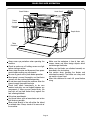
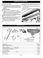
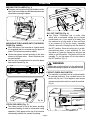
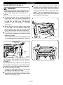
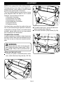
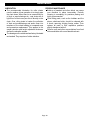
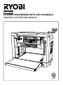
AP13AK
PLANER THICKNESSER WITH ANTI KICKBACK
OWNER’S OPERATION MANUAL
N197
TABLE OF CONTENTS
Table of Contents
1
Specificatons
1
Rules for Safe Operation
2-4
Loose Parts List
4
Operation
5
Adjustment
6-9
Maintenance
10
Troubleshooting
11
PRODUCT SPECIFICATIONS
Input
2000 watt
No Load Speed
9000 R.P.M.
Min Planing Length
127 mm
Max Planing Width
318 mm
Planing Height
5 - 153 mm
Depth Per Pass
3 mm
Feeding Speed
8m / min
Binder
48mm with 2 blades,
9000 R.P.M. ie 18000 C.P.M.
Weight
32 - 30.5 kg
Look for this symbol to point out important safety precautions. It means attention!!!
Your safety is involved.
Page 1
RULES FOR SAFE OPERATION
The purpose of safety rules is to attract your attention to
possible dangers. The safety symbols and the explanations with
them, require your careful attention and understanding.
The safety warnings by themselves do not elimimate any danger.
The instruction or warnings they give are not substitutes for
proper accident prevention measures.
SAFETY ALERT SYMBOL. Indicates caution or
warning. May be used in conjunction with other
symbols or pictures.
WARNING: Failure to obey a safety warning can
result in serious injury to yourself or to others. Always
follow the safety precautions to reduce the risk of fire,
electric shock and personal injury.
DOUBLE INSULATION
Double insulation is a concept in safety in electric power tools,
which eliminates the need for earth grounding. Whenever
there is electric current in the tool there are two complete sets
of insulation to protect the user. All exposed metal parts are
isolated from the internal metal motor components with
protecting insulation.
WARNING: The double insulated system is intended to protect
the user from shock resulting from a break in the tool's internal
wiring. Observe all normal safety precautions related to avoiding
electrical shock.
IMPORTANT: Servicing of a tool with double insulation requires
extreme care and knowledge of the system and should be
performed only by a qualified service technician. For service we
suggest you return the tool to your nearest Ryobi Authorised
Service Centre for repair. When servicing, use only identical
Ryobi replacement parts.
WARNING: Do not attempt to operate this tool until you have
read thoroughly and completely understood the safety rules, etc.
contained in this manual. Failure to comply can result in accidents
involving fire, electric shock or serious personal injury. Save
owners manual and review frequently for continual safe operation
and for instructing others who may use this tool.
The operation of any tool can result
in foreign objects being thrown into
your eyes, which can result in severe
eye damage. Before beginning power
tool operation, always wear safety
goggles or safety glasses with side
shields and a full face shield when
needed. We recommend Wide Vision Safety Mask for use over
eye glasses or standard safety glasses with side shields.
6. STORE IDLE TOOLS. When not in use, tools should be stored
in a dry and high or locked-up place, out of reach of children.
7. DON'T FORCE TOOL. It will do the job better and safer at the
rate at which it was designed.
8. USE RIGHT TOOL. Don't force a small tool or attachment to
do the job of a heavy duty tool. Don't use tool for any purpose
not intended.
9. DRESS PROPERLY. Do not wear loose clothing or jewellery.
They can be caught in moving parts. Rubber gloves and
non-skid footwear are recommended when working outdoors.
Also wear protective hair covering to contain long hair.
10. ALWAYS WEAR SAFETY GLASSES. Everyday eyeglasses
have only impact resistant lenses, they are not safety glasses.
11. PROTECT YOUR LUNGS. Wear a dust mask if operation is dusty.
12. PROTECT YOUR HEARING. Wear hearing protection during
extended periods of operation.
13. DON'T OVERREACH. Keep proper footing and balance at all
times. Do not use tool on a ladder or unstable support.
Secure tools when working at elevated levels.
14. MAINTAIN TOOLS WITH CARE. Keep tools sharp and clean
for better and safer performance. Follow instructions for
lubricating and changing accessories.
15. DISCONNECT TOOLS. When not in use, before servicing, or
when changing attachments, blades, bits, cutters, etc. all
tools should be disconnected.
16. REMOVE ADJUSTING KEYS AND WRENCHES. Before
turning it on, Form a habit of checking to see that keys and
adjusting wrenches are removed from tool.
17. NEVER USE IN AN EXPLOSIVE ATMOSPHERE. Normal
sparking of the motor could ignite fumes.
18. KEEP HANDLES DRY, CLEAN AND FREE FROM OIL AND
GREASE. Always use a clean cloth when cleaning. Never use
brake fluids, gasoline, petroleum based products, or any
strong solvents to clean your tool.
19. STAY ALERT AND EXERCISE CONTROL. Watch what you
are doing and use common sense. Do not operate tool when
you are tired. Do not rush.
20. CHECK DAMAGED PARTS. Before further use of the tool, a
guard or any other part that is damaged should be carefully
checked to determine that it will operate properly and perform
its intended function. Check for alignment of moving parts,
binding of moving parts, breakage of parts and any other
conditions that may affect its operation. A guard or any other
part that is damaged should be properly repaired or replaced
by an authorised service centre.
1. KNOW YOUR POWER TOOL. Read owners manual carefully.
Learn its applications and limitations as well as the specific
potential hazards related to this tool.
2. GUARD AGAINST ELECTRICAL SHOCK BY PREVENTING
BODY CONTACT WITH GROUNDED SURF ACES.
For example, pipes, radiators, ranges, refrigerator enclosures.
3. KEEP WORK AREA CLEAN. Cluttered areas and benches
invite accidents.
4. AVOID DANGEROUS ENVIRONMENT. Don't use power
tools in damp or wet locations or expose to rain. Keep work
area well lit.
5. KEEP CHILDREN AND VISITORS AWAY. Visitors should wear
safety glasses and be kept a safe distance from work area.
Do not let visitors contact tool or extension cord.
21. DO NOT USE TOOL IF SWITCH DOES NOT TURN IT ON
AND OFF. Have defective switches replaced by authorised
service centre.
22. DO NOT OPERATE THIS TOOL WHILE UNDER THE
INFLUENCE OF DRUGS, ALCOHOL OR ANY MEDICATION.
23. SUPPLY CORD. If the supply cord is damaged, it must be
replaced by the manufacturer or its service agent or similarly
qualified person in order to avoid a hazard.
Due to Ryobi's continued product refinement policy,
product features and specifications can and will change
without notice. Check current features and specifications with your Ryobi retailer.
Page 2
SAVE THESE INSTRUCTIONS
RULES FOR SAFE OPERATION
Hand Crank
Stock Rollers
Power
Switch
Overload
Switch
Depth Scale
Table
Extention
Always wear eye protection when operating the
machine.
Check to make sure all holding screws are tight
before starting machine.
Always stop the motor and disconnect from power
source before making any adjustments.
Be sure all guards are in place before operation.
Read owner’s manual thoroughly and familiarise
yourself with the machine before operation.
Do not force work through the machine. Allow the
planer to apply the proper feed rate.
Check feed rollers occasionally to be sure
sawdust and chips are not lodged between any
components. If rollers are not seated firmly, the
feed rolls will not hold timber firmly against the
bed, allowing kickback.
Only plane wood boards.
Use sound timber, with no loose knots and as few
tight knots as possible.
Never stand directly in line with either the infeed
or outfeed sides. Always stand off to one side of
the machine.
Page 3
Make sure the workpiece is free of from nails,
screws stones and other foreign objects which
could damage the blades.
Make sure the blades are attached correctly as
described in the instructions.
Use caution when handling the blades and
cutterhead assembly. The blades are sharp and
can easily cut your hand.
Allow the cutterhead to reach full speed before
using.
RULES FOR SAFE OPERATION
Anti-Kickback Pawls
Device which, when properly installed and maintained,
is designed to stop the workpiece from being kicked
back toward the front of the Blade during a Planer
operation.
Avoiding kickback
Always use the correct Blade depth setting.
Inspect the work for knots or nails before
beginning a cut. Knock out any loose knots with a
hammer, never cut into a loose knot or nail.
Always use clear, sharp, and properly-set blades.
Never make planer with dull blades.
To avoid pinching the Blade, support the work
properly before beginning a planer operation.
When making a planer operation, use steady,
even pressure, never force to plane.
Do not plane wet or warped timber.
Always hold your workpiece firmly with both
hands, keep your body in a balanced position to
be ready to resist kickback. Never stand directly
in line with timber.
LOOSE PARTS LIST
1
2
9
4
3
7
5
6
10
8
• Properly assembled
blade setting guage.
1) “C” Circlip ......................................................................................................................................... 4 pieces
2) Blade Setting Guide ..........................................................................................................................2 pieces
3) Blade Setting Guage Shaft .................................................................................................................1 piece
4) Base Lock Screw ......................8mm x 50(L)................................................................................... 4 pieces
5) Elevation Knob Lock Screw ......6mm x 15(L)..................................................................................... 1 piece
6) Cutterhead Raising Hand Crank ........................................................................................................1 piece
7) Allen Wrenches ............................................................................................................................... 4 & 5mm
8) Open End Wrench ..........................8 x 10..........................................................................................1 piece
9) Dust Chute..........................................................................................................................................1 piece
10) Philip Screws...................................................................................................................................4 pieces
Page 4
OPERATION
MOVING THE PLANER (Fig. 1)
The planer can be carried using the handles on either
side of the frame. Make sure the table extensions are
closed before moving the planer.
Fig. 3
Fig. 1
MOUNTING THE PLANER ONTO THE WOOD
BASE (Fig. 2a&2b)
When the planer is not mounted on a planer stand,
it is suggested that it be mounted onto two pieces of
timber. This will ensure maximum stability.
Choose two pieces of wood according to the sizes
shown on the figure below . Mount the planer onto
the wood surface.
Use four long, furnished screws to mount the planer
base onto the wood (Fig. 2a)
2-Ø9
ON / OFF SWITCH (Fig. 4)
Your Planer Thicknesser has a rocker style
switch with a removable locking key to prevent
unauthorised use. If you intend to be away from
the machine for a long period of time and there
is any chance of it’s use by others, especially
children, remove the locking key with the switch in
the OFF position. Store the locking key in a safe,
inconspicuous place in your workshop. To turn
the planer on, insert the locking key and turn the
switch to the ON position. The planer will then be
operable. To turn the planer off, turn the switch to
the OFF position. (Fig. 4)
WARNING:
Always be sure the switch is in the off position
before connecting the planer to the power source.
50.8
Ø9
50.8
Mounting
Hole
Planer Base
Hole
15
Ø15
m8 crew
CIRCUIT OVERLOAD SWITCH
The machine is provided with an overload switch
for overload protection. If an overload occurs, the
switch will pop out. If this happens, wait several
minutes and press the switch to reset the machine.
(Fig. 4)
Fig. 2a
On/Off Switch
Circuit Overload
Switch
Fig. 2b
STOCK ROLLERS (Fig. 3)
Two rollers are built on top of the planer, providing
convenient handling of stock for consecutive cutting
operations. Stock placed on the top of the machine
can be easily pulled to the operator for planing.
Page 5
On/Off Switch
Locking Key
Fig. 4
ADJUSTMENT
ADJUST DEPTH OF CUT (Fig. 5)
When you have properly adjusted the depth of
cut scale, test your reading by planing a piece of
scrap timber. After planing, measure the planed
thickness and double check it against the scale
reading. The two measurements should be the
same, re-adjust your depth of cut scale to read the
planed thickness if necessary.
WARNING:
Never plane more than 3mm in one pass and
never attempt to plane a board under 127mm
(5”) in length. Always wear a protective face
shield.
To adjust the depth of cut, turn the cutterheadraising hand crank in the direction marked on top
of the planer. The depth of cut adjustment can
be read from the depth scale. The adjustment
gradation is 2mm per revolution of the hand
crank.(Fig. 5)
Always start your work by making a light planing
cut. The depth of cut on subsequent passes may
be increased by up to 3mm, but remember that a
light cut creates a finer finish than a heavier cut.
The thickness of timber running through the planer
is controlled by the distance you adjust the cutting
blade from the table.
• Do not plane timber which is less than 5mm thick.
• Do not plane timber which is thicker than 153mm (6”).
Screws
Chip Deflector
Safety Guard
Fig. 6
Cutterhead Raising
Hand Crank
Depth
Scale
Plastic Pointer
Fig. 5
Screws
ADJUSTING THE DEPTH OF CUT SCALE
(Fig 6&7)
For safe operation of your planer, it is very important
that the depth of cut scale is read accurately. To adjust
the depth of cut scale, follow the steps outlined below:
Try to feed a board for planing.
Compare the measured thickness of the board to
the reading on the depth of cut scale.
If the reading on the depth of cut scale is incorrect,
loosen the screw which tightens the plastic pointer
and adjust accordingly (Fig. 5)
Page 6
Fig. 7
ADJUSTMENT
REMOVING THE PLANER BLADES (Fig. 7a)
To remove the planer blades, follow the steps outlined
below:
WARNING:
Unplug your planer from the power source before
removing the planer blades.
Remove the chip guard by removing the wing nut
on each side.
Loosen the lock bar (B) and blade by turning the
lock screws (A) clockwise. The blades are spring
loaded, and will push out when the assembly is
loosened. (Fig. 7a)
Take out the blade (C), and then the blade lock
bar (B).
SETTING THE BLADE HEIGHT (Fig. 8&8a)
To obtain a blade projection of 1.5mm, place the
blade setting gauge (E) on the cutterhead with both
guides resting firmly against the blade. (Fig. 8)
Loosen the assembly by turning the 7 screws (A)
clockwise with an open end wrench.
When the blade is pressed to the required height
by guides on the gauge, retighten the assembly by
turning the screws counter clockwise. Make sure
all seven lock screws are tightened securely.
WARNING:
The blade edge is very susceptible to chipping.
Use caution when handling the gauge near the
blades to avoid damaging them.
WARNING:
The assembly must be tightened securely to
prevent accidents during planing.
Fig. 7a
INSTALLING THE PLANER BLADES (Fig. 7a)
WARNING:
Unplug your planer from the power source before
removing the planer blades.
To install the planer blades, follow the steps outlined
below:
Remove the blades according to the instructions
for “ REMOVING THE PLANER BLADES”
Fit the blade lock bar (B) into the slot on the
cutterhead.
Fit the blade into the slot on the cutterhead, and
tighten the lockbar blade assembly by turning the
screws counter clockwise. Make sure the blade is
facing the correct direction.
Set the blade heights according to the instructions
as shown below. The blade height must be reset
every time the blades are taken out for any
reason.
Be sure to replace the chip guard after blades
are installed.
Page 7
Fig. 8
Fig. 8a
ADJUSTMENT
MAKING THE CUTTERHEAD AND WORKTABLE
PARALLEL (Fig. 9~12)
Plane a workpiece and measure thickness after the
cut. If the thickness is not the same on both sides of
the workpiece, perform the following action.
Adjust the cutter shaft and the worktable so they are
parallel. The tools used for checking are shown below
. Please use hardwood to make a tool guage block
according to the size shown in the figure 9. Make the
adjustments as per the following procedures.
Remove height adjustment handle and both top
and side covers by removing allen screws (Fig.11)
to expose height adjustment lock nuts. (Fig.12)
Loosen adjustment lock nut. (Fig.12)
Adjust height nut up or down as required to suit
guage block. (Fig.10)
When desired height setting is reached, tighten
lock nuts inposition. (Fig.12)
Reassemble side and top covers and replace
height adjustment handle.
20mm
34mm
135°
Fig. 10
Height Adjustment
Crank Handle
Allen
Screws
5mm
33mm
33mm
Fig. 11
100mm
Height
Adjustment Nut
3mm
120°
70mm
15mm
30mm
100mm
Fig. 12
Fig. 9
Page 8
ADJUSTMENT
NOTE: Remove gauge block before starting machine.
Thickness planing is the sizing of the material to a
desired thickness, while creating a smooth surface
parallel to the opposite side of the board.
The art of thickness planing consists mainly of using
good judgement about the depth of cut in various
situations. You must take into account:
1) The width of the timber
2) The hardness of the board
3) The dampness of the board
4) The straightness of the board
5) The grain direction
6) The grain structure
How these factors can effect the quality of the work
can only be learned through experience. Whenever
working with a new type of wood, or one with unusual
problems, always make test cuts on scrap material
prior to working on the actual piece.
FOR ADDITIONAL PLANING
If additional planing is needed to obtain the desired
thickness or finish, hand crank the cutterhead no more
than 3mm (at any one time) and complete another
pass.
Wing Nuts
Steel Cover
Fig. 13a
To install the dust chute , remove the steel cover
first by unscrewing the 2 wing nuts.
Fix the dust chute with 4 philip screws (Fig 13b)
Dust Chute
WARNING:
Never plane more than 3mm in one pass and
never attempt to plane a board under 127mm
(5”) in length. Always wear a protective face
shield.
Screws
INSTALLING THE DUST CHUTE
Currently, the planer is assembled with a steel
cover , which is fixed by 2 wing nuts (Fig. 13 & 13a)
Wing Nuts
Fig. 13
Page 9
Fig. 13b
MAINTENANCE
LUBRICATION
The recommended lubrication for roller chains
used in medium to low operation is to simply wipe
the chain clean. When there is an excess build up
of dust or wood shavings etc., coat chain with a
light film of oil but never pour the oil directly on the
chain. Over -oiling tends to hasten the collection
of dust and woodshavings and works them into
members of the chain leading to increased wear
and premature replacement. This applies to the
speed reduction and height adjustment chains as
well as the elevation screws.
The bearings on the cutterhead are factory lubricated
and sealed. They require no further attention.
PERIODIC MAINTENANCE
Build-up of sawdust and other debris can cause
your machine to plane inaccurately. Periodic
cleaning is mandatory for precision planing and
highly recommended.
Close fitting parts, such as the lockbars and the
planer cutterhead slots, should be cleaned with
a brush; removing clinging foreign matter. Then
replace all parts in their respective positions
slightly dampened with oil.
Remove resin and other accumulations from feed
rollers and table with a non-flamable solvent.
Page 10
TROUBLESHOOTING
PROBLEM
POSSIBLE CAUSE
REMEDY
FUZZY GRAIN
1. Planing wood with high moisture
content.
1. Dry the wood
2. Sharpen Blades.
2. Dull Blades.
TORN GRAIN
1. Too heavy a cut.
2. Blades cutting against the grain.
3. Dull Blades.
1. Review proper depth of cut
2. Feed wood with the grain, or turn
workpiece around.
3. Sharpen Blades.
RO U G H / R A I S E D
GRAIN
1. Dull Blades.
2. Tool heavy a cut.
3. Moisture content too high
4. Cutterhead bearings damages.
1. Sharpen Blades.
2. Review proper depth of cut
3. Dry the wood.
4. Replace bearings.
UNEVEN DEPTH OF
CUT SIDE TO SIDE
1. Blade projection not uniform.
2. Cutterhead not levelled to planer
bed.
1. Adjust Blade projection.
2. Level cutterhead to table.
BOARD THICKNESS
D O E S N ' T M AT C H
DEPTH OF CUT SCALE
1. Depth of cut scale incorrect.
1. Adjust depth of cut scale.
CHAIN JUMPING
1. Sprockets misaligned.
2. Sprockets worn.
1. Align sprockets.
2. Replace sprockets.
MACHINE WON'T
START / RESTART
1. Not plugged in.
2. Circuit breaker / fuse.
3. Motor failure.
4. Loose wire.
5. Overload reset has not reset.
6. Motor starter failure.
1. Check power source.
2. Check power source.
3. Have motor checked.
4. Have motor checked by authorised
Ryobi service agent.
5. Allow machine to cool down and restart.
6. Have motor starter checked by authorised
Ryobi service agent.
REPEATED CIRCUIT 1. Extension cord too long or too thin. 1. Use a shorter or thicker extension cord.
TRIPPING RESULTING 2. Blades too dull.
2. Sharpen or replace Blades.
IN MOTOR STOPPAGE 3. Low voltage running.
3. Check voltage.
POOR FEEDING OF 1. Planer table dirty.
TIMBER
2. Feed roller damaged
3. Sprocket damaged.
4. Gear box malfunction.
1. Clean off pitch and residue, and lubricate
planer table.
2. Replace.
3. Replace.
4. Check gear box.
WORKPIECE JAMMED
1. Set the Blade to the correct height.
1. Inadequate Blade setting height.
Page 11
NOTE
Page 12
RYOBI TECHNOLOGIES AUSTRALIA PTY. LTD.
GUARANTEE
Subject to the guarantee condition below, this Ryobi tool
(hereinafter called “the product”) is guaranteed by Ryobi
(hereinafter called “the Company”) to be free from
defects in material or workmanship for a period of 24
months from the date of original purchase covering
both parts and labour. Under the terms of this
guarantee, the replacement shall be the opinion of
the Company or its authorised agent. Should service
become necessary during the warranty period,
the owner should contact the RYOBI HELPLINE
1300 361505, or the Ryobi retailer from where the
product was purchased.In order to obtain guarantee
service, the owner must present the sales docket and
Guarantee Certificate to confirm date of purchase. This
product is sold by the dealer or agent as principal and
the dealer has no authority from the Company to give
any additional guarantee on the Company’s behalf
except as herein contained or herein referred to.
Guarantee Conditions
This guarantee only applies provided that the Product
has been used in accordance with the manufacturer’s
recommendations under normal use and reasonable
care (in the opinion of the Company) and such
guarantee does not cover damage, malfunction or
failure resulting from misuse, neglect, abuse, or
used for a purpose for which it was not designed
or is not suited and no repairs, alterations or
modifications have been attempted by other than
an Authorised Service Agent. This guarantee will not
apply if the tool is damaged by accident or if repairs
arise from normal wear and tear.
The Company accepts no additional liability pursuant to
this guarantee for the costs of travelling or
transportation of the Product or parts to and from the
service dealer or agent - such costs are not included
in this guarantee.
Certain legislation, including the Trade Practices Act,
1974 (as amended) and other state and territorial laws
give rights to the buyer and impose liability on the seller
in certain circumstances. Nothing herein shall have the
effect of excluding, restricting or modifying any
condition, guarantee, right or liability imposed, to the
extent only that such exclusion, restriction or
modification would render any term herein void.
RYOBI TECHNOLOGIES AUSTRALIA PTY. LTD.
A.B.N. 98 002 277 509
SYDNEY: 359-361 Horsley Road, Milperra, N.S.W. 2214.
Contact during normal business hours.
Tel: (02) 9792 9800 - Fax: 1800 807 993 - www.ryobi.com.au
BRISBANE:
TOWNSVILLE:
MELBOURNE:
All enquiries Tel : 1300 361 505
All enquiries Tel : 1300 361 505
960 Stud Road, Rowville,Vic. 3178
Tel : (03) 9764 8656
HOBART:
All enquiries Tel : 1300 361 505
ADELAIDE:
All enquiries Tel : 1300 361 505
PERTH:
33-35 Sorbonne Cres., Canning Vale,W.A. 6155.
Tel : (08) 9455 7775
RYOBI NEW ZEALAND PTY. LTD.
AUCKLAND: 27 Clemow Drive, Mt Wellington, N.Z.
Tel: (09) 573 0230 - Free Call: 0800 279 624 - Fax: (09) 573 0231 - www.ryobi.co.nz
Contact during normal business hours.
This Guarantee Form Should Be Retained By The Customer At All Times
For your record and to assist in establishing date of purchase (necessary for in-guarantee service)
please keep your purchase docket and this form completed with the following particulars.
Purchased From
Address Of Dealer
Date
Model No
Serial No
Present This Form With Your Purchase Docket When Guarantee Service Is Required.