1
The WellPro Automated
Liquid Handling System
ProGroup
Instrument Corp.
1-800-471-1916
www.wellpro.us
WellPro 96 and 384 Liquid Handler
User Manual
User Manual Rev. 2.0; November 2004
tm
NOTE: This manual is written to be used for either the WellPro 96 or WellPro 384 instruments. The
instruments vary in that the liquid heads are specifically designed for either a 96 or 384 well
microplate. The WellPro 96 uses a 12 channel liquid head with 200ul capacity tips, and the WellPro 384
uses a 24 channel liquid head with 50ul capacity tips.
The examples given in the text have been written for the WellPro 384 ie; Rows A to P, Columns 1 to 24,
transfer volumes 50ul max, etc. When using the WellPro 96 the appropriate volumes and positions will
be displayed on the hand controller. The tutorial examples given can be followed for either instrument.
WellPro 96 specs are included on this CD-ROM under the WellPro 96 Brochure. If you prefer a hard copy
of this manual exclusively for the WellPro 96 please contact Customer Service at 1-800-471-1916, 1-618258-7393, or www.wellpro.us
Trademarks
WellPro Automated Liquid Handling System is a registered trademark of ProGroup Instrument Corp. All
other trademarks and registered trademarks are property of their respective holders.
Disclaimer
ProGroup reserves the right to change its products and services at any time to incorporate technological
developments. This manual is subject to change without prior notice as part of a continuous product
development. Although this manual has been prepared with every precaution to ensure accuracy,
ProGroup assumes no liability for any errors or omissions, nor for any damages resulting from the
application or use of this information. This manual supersedes all previous editions.
No liability for consequential damages
ProGroup shall not be liable for any damages whatsoever arising out of the use or inability to use this
product.
Printed in the United States
Safety Sybols and Markings
SAFETY SYMBOLS AND MARKINGS
These symbols are intended to draw your attention to essential information and alert you to the
presence of hazards as indicated. Some of these symbols may not appear in the manual or on the
product:
SAFETY SYMBOLS used in the WellPro Model 384 Liquid Handler
Power ON
Power OFF
WARNING MARKINGS used in the documentation
Caution: risk of electric shock.
Caution: biohazard risk.
Caution: risk of personal injury to the operator or a safety hazard to the
surrounding area.
Caution: risk of damage to the instrument, other equipment or loss of
performance or function in a specific application.
WellPro User Manual
01.11.04
iii
About the User Manual
ABOUT THE USER MANUAL
This User Manual has been written for the user (e.g. laboratory technician) and provides information on
the WellPro Model 384 Liquid Handler. This manual contains the installation and operating instructions
for the WellPro Model 384 Liquid Handler. Read the manual in its entirety prior to operating the
instrument.
This User Manual has been designed to give you the information you need to:
•
•
•
•
Review safety precautions.
Install the WellPro Model 384 Liquid Handler.
Use the WellPro Model 384 Liquid Handler in routine analyses and research.
Perform basic maintenance procedures.
This User Manual also describes features and specifications of the WellPro Model 384 Liquid Handler
hardware and on-board software.
WellPro User Manual
01.11.04
iv
Table of Contents
TABLE OF CONTENTS
SAFETY SYMBOLS AND MARKINGS....................................................................................................................................III
ABOUT THE USER MANUAL ............................................................................................................................................... IV
TABLE OF CONTENTS .......................................................................................................................................................... V
1
INTRODUCTION............................................................................................................................................................. 1
1.1
OVERVIEW .................................................................................................................................................................... 1
1.2
PRINCIPLE OF OPERATION .............................................................................................................................................. 2
1.2.1
Controller ........................................................................................................................................................ 2
1.2.2
Liquid Handling Unit ...................................................................................................................................... 2
1.2.3
WellPro Reagent Containers....................................................................................................................... 2
1.2.4
WellPro Templates ........................................................................................................................................ 3
1.3
ABOUT THE USER MANUAL ............................................................................................................................................ 4
2
INSTALLATION PROCEDURES ..................................................................................................................................... 5
2.1
2.2
2.3
2.4
2.5
3
SYSTEM COMPONENTS ............................................................................................................................................... 7
3.1
3.2
3.3
3.4
4
OVERVIEW .................................................................................................................................................................... 5
LOCATION OF THE UNIT IN THE LABORATORY .................................................................................................................. 5
POWER REQUIREMENTS ................................................................................................................................................. 5
UNPACKING AND INSPECTION ......................................................................................................................................... 6
INITIAL INSTALLATION OF THE WELLPRO 384 LIQUID HANDLER ....................................................................................... 6
INTRODUCTION .............................................................................................................................................................. 7
WELLPRO WP384 CONTROLLER ................................................................................................................................... 7
THE WELLPRO WP384 LIQUID HANDLING UNIT ............................................................................................................. 7
THE WELLPRO REAGENT CONTAINER ............................................................................................................................. 7
ESTABLISHING A FILE USING THE CONTROLLER ...................................................................................................... 8
4.1
INTRODUCTION .............................................................................................................................................................. 8
4.2
THE KEYPAD CONTROLLER ............................................................................................................................................ 8
4.2.1
The Display ...................................................................................................................................................... 8
4.2.2
The Keypad ..................................................................................................................................................... 9
4.2.3
Clear .................................................................................................................................................................. 9
4.2.4
Start.................................................................................................................................................................. 9
4.2.5
Step.................................................................................................................................................................10
4.2.6
Stop.................................................................................................................................................................10
4.2.7
Help .................................................................................................................................................................10
4.2.8
File ...................................................................................................................................................................10
4.2.9
Yes/No ...........................................................................................................................................................11
4.2.10 Enter ...............................................................................................................................................................11
4.3
ENTERING DATA INTO A FILE........................................................................................................................................11
4.4
FILE 0 ........................................................................................................................................................................11
5
PLATE FILLING ............................................................................................................................................................ 12
5.1
5.2
5.3
5.4
5.5
OVERVIEW ..................................................................................................................................................................12
EDITING A PLATE FILLING FILE......................................................................................................................................12
STORING/OVERWRITING THE FILE ................................................................................................................................16
RUNNING A PLATE FILLING FILE ....................................................................................................................................16
SAMPLE PLATE FILLING EXPERIMENT............................................................................................................................17
WellPro User Manual
01.11.04
v
Table of Contents
6
SERIAL DILUTION........................................................................................................................................................ 19
6.1
6.2
6.3
6.4
6.5
7
OVERVIEW ..................................................................................................................................................................19
EDITING A SERIAL DILUTION FILE ..................................................................................................................................19
STORING/OVERWRITING THE FILE ................................................................................................................................23
RUNNING A SERIAL DILUTION FILE.................................................................................................................................23
SAMPLE SERIAL DILUTION EXPERIMENT ........................................................................................................................24
PLATE TO PLATE TRANSFER ................................................................................................................................... 26
7.1
7.2
7.3
7.4
7.5
7.6
8
OVERVIEW ..................................................................................................................................................................26
TYPES OF PLATE TO PLATE TRANSFER .........................................................................................................................26
EDITING A PLATE TO PLATE TRANSFER FILE .................................................................................................................27
STORING/OVERWRITING THE FILE ................................................................................................................................31
RUNNING A PLATE TO PLATE TRANSFER .......................................................................................................................31
SAMPLE SERIAL DILUTION EXPERIMENTS ......................................................................................................................32
EMPTYING A PLATE................................................................................................................................................... 36
8.1
8.2
8.3
8.4
9
OVERVIEW ..................................................................................................................................................................36
EDITING AN EMPTYING A PLATE FILE ............................................................................................................................36
STORING/OVERWRITING THE FILE ................................................................................................................................39
RUNNING AN EMPTY A PLATE FILE ...............................................................................................................................39
TIME DELAY FILE........................................................................................................................................................ 40
9.1
9.2
9.3
9.4
10
10.1
10.2
10.3
11
OVERVIEW ..................................................................................................................................................................40
EDITING A TIME DELAY FILE.........................................................................................................................................40
STORING/OVERWRITING THE FILE ................................................................................................................................42
USING A TIME DELAY FILE ...........................................................................................................................................42
LINKING FILES ......................................................................................................................................................... 43
OVERVIEW ..............................................................................................................................................................43
USING LINKED FILES ................................................................................................................................................43
A TYPICAL SERIES OF OPERATION USING LINKED FILES .............................................................................................43
ADJUSTING THE TIP HEIGHT ................................................................................................................................ 45
11.1
OVERVIEW ..............................................................................................................................................................45
11.1.1 Editing/Running the Tip Height Adjustment File ...............................................................................45
11.1.2 Setting the Tip Height ...............................................................................................................................46
12
CALIBRATION PROCEDURES ................................................................................................................................. 49
12.1
INTRODUCTION ........................................................................................................................................................49
12.2
THE GRAVIMETRIC METHOD ....................................................................................................................................49
12.2.1 Materials Required ......................................................................................................................................50
12.3
CALIBRATION PROCEDURE .......................................................................................................................................51
12.4
CALCULATIONS........................................................................................................................................................53
12.5
CALIBRATION OF NON-AQUEOUS OR VISCOUS SOLUTIONS...........................................................................................55
12.5.1 Introduction..................................................................................................................................................55
12.5.2 Procedure......................................................................................................................................................55
12.6
QUALITY CONTROL PROCEDURES .............................................................................................................................57
12.6.1 Verification ...................................................................................................................................................58
WellPro User Manual
01.11.04
vi
Table of Contents
13
OPERATING HINTS AND MAINTENANCE............................................................................................................. 59
13.1
OVERVIEW ..............................................................................................................................................................59
13.2
TIPS .......................................................................................................................................................................59
13.3
POWER INTERRUPTIONS ...........................................................................................................................................59
13.4
MAINTENANCE ........................................................................................................................................................60
13.4.1 Preventive Maintenance ...........................................................................................................................60
13.4.2 Cleaning up Spills .........................................................................................................................................60
13.4.3 Piston Plungers ............................................................................................................................................60
13.4.4 Table Rails......................................................................................................................................................60
13.4.5 Cleaning the Plastic Cover ........................................................................................................................60
13.4.6 Fuse Replacement.......................................................................................................................................61
13.5
TROUBLESHOOTING .................................................................................................................................................61
14
WELLPRO WP384 SPECIFICATIONS..................................................................................................................... 62
WellPro User Manual
01.11.04
vii
Section 1: Introduction
1 INTRODUCTION
1.1
Overview
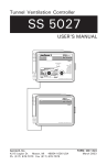
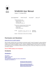
The ProGroup WP384 Liquid Handler (Figure 1.1) is designed to perform the following liquid handling
activities on a user-programmable basis:
•
•
•
•
•
•
•
Precisely transfer liquids in volumes from 1 µL to 50 µL using disposable tips
Perform serial dilutions in almost any ratio,
Perform serial dilutions of 16 wells or 24 wells simultaneously
Precisely mix the contents of a microplate
Transfer samples to or from microplates
Perform mother-daughter “repli-plating”
Add a reagent to the wells on a plate at a user specified time
Fig 1.1 WellPro WP384 Liquid Handler
1
Section 1: Introduction
1.2
Principle of Operation
The WellPro WP384 Liquid Handler consists of a hand-held controller and a liquid handling unit. A variety
of reagent containers can be used to hold liquids that will be added to the cells in a plate (or have been
removed from a plate).
1.2.1 Controller
The WellPro WP384 Liquid Handler includes a keyboard and display that are used to program all
operations of the unit. The controller allows the user to control parameters such as the volumes to
transfer, mix, or dispense, the transfer speed, and whether to change tips between transfers.
1.2.2 Liquid Handling Unit
The WellPro WP384 Liquid Handler is an electro-mechanical transfer unit that is comprised of two basic
parts: a table and a vertical head assembly.
The table accommodates a series of interchangeable templates which position the reagent containers
and a magazine with the disposable tips, etc. During operation, the table slides back and forth to bring
the appropriate component under the head assembly.
The head assembly consists of three basic parts:
•
•
•
a plunger housing which contains nozzles that press into the tips to form airtight seals
a plunger block which moves up and down to aspirate and deliver samples
a tip ejector plate which removes used tips
The head assembly slides up and down to bring the tips to the appropriate height to perform the
designated operations.
In most instances, a 24 channel (tip) air displacement pipetting head is used on the WellPro WP384 Liquid
Handler and most protocols are designed to be performed in the 24 channel mode, but serial dilutions
can be performed in the 16 channel mode to allow for maximum dilution capability with the 384 well
plate.
1.2.3 WellPro Reagent Containers
The WellPro liquid handler can be used with a variety of MICROTROF reagent containers, each of which
consists of three reservoirs. Each reservoir holds a different amount of liquid: (e.g. 20 mL, 58 mL, and 77
mL). You can use the reservoirs to hold reagents that will be added to a plate or waste that has been
removed from a plate. In addition, some MICROTROFs include a station for storage of microtips.
2
Section 1: Introduction
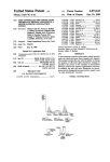
1.2.4 WellPro Templates
The WellPro WP384 liquid handler uses a template to position microplates, reagent containers and tip
magazines on the movable table.
Two templates are provided:
•
Standard Template (24 Across)
A general purpose template (Template 1 - "24 Across") is used for liquid handling operations when
the 24 well rows on the plate are oriented across the front of the instrument as shown in Figure 1.2.
Fig 1.2 Standard Template
•
Serial Dilution Template (16 Across)
The Serial Dilution template "16 Across") is used when serial dilution is to be performed lengthwise
on a plate. In this case, the plate is oriented such that the 16 wells of a column face the front of the
instrument. (Figure 1.3).
Fig. 1.3 Serial Dilution Template
3
Section 1: Introduction
1.3
About the User Manual
This User Manual has been written for the end user of the system (e.g. a laboratory technician) and
provides information about the operation and maintenance of the WellPro WP384 Liquid Handler.
Read the manual in its entirety prior to operating the instrument.
This User Manual has been designed to give you the information you need to:
•
•
•
•
Review safety precautions.
Install the system
Use the system in routine jobs and research.
Perform basic maintenance procedures.
This User Manual also describes features and specifications of the WellPro WP384 Liquid Handler.
This manual includes the following sections:
•
•
•
•
•
•
•
•
•
•
•
•
•
Installation (Chapter 2)
System Components (Chapter 3)
Establishing a File (Chapter 4)
Plate Filling (Chapter 5)
Serial Dilution (Chapter 6)
Plate to Plate Transfer (Chapter 7)
Emptying a Plate (Chapter 8)
Time Delay Files (Chapter 9)
Linking Files (Chapter 10)
Adjusting the Tip Height (Chapter 11)
Calibration Procedures (Chapter 12)
Operating Hints and Maintenance (Chapter 13)
Specifications (Chapter 14)
In addition, a series of appendices include the warranty and ordering information.
4
Section 2: Installation Procedures
2 INSTALLATION PROCEDURES
2.1
Overview
The WellPro 384 Liquid Handler is designed to be installed by the operator. This chapter describes how
the unit is to be unpacked and assembled.
2.2
Location of the Unit in the Laboratory
The unit should be installed in a facility with the following conditions:
•
•
•
•
The temperature should be maintained between 20-26oC (68-79oF). To prevent temperature
fluctuations, do not place the WellPro 384 liquid handler in direct sunlight, near equipment that gives
off heat, or under heating or air conditioning outlets.
If flammable or toxic solvents are to be used, a suitable ventilation system should be provided.
The use of open flames in the laboratory should be prohibited.
Corrosive vapors or dust should not be present as these materials can adversely affect the long-term
performance of the system.
The Well-Pro fluidics module requires approximately xx mm (yy”) of linear bench space. In addition, the
controller requires xx cm (yy”).
Note: Place the WellPro 384 on a stable, level bench or hood. Excessive jarring or vibration during
operation may affect its performance.
2.3
Power Requirements
The WellPro 384 Liquid Handler to designed to operate at 100, 120, 220 or 240 V (50/60 Hz) with a
maximum power consumption of 360 watts. The operating potential is set at the factory and is
indicated on the serial number tag on the rear panel of the system.
WARNING
WARNING: Verify that this voltage is correct for your location before installation.
CAUTION
CAUTION: WellPro 384 Liquid Handlers shipped to locations in the United States and Canada are
supplied with a standard three-conductor power cable and a three-terminal plug that provides
an earth ground. The unit MUST be connected to a three-terminal socket that is properly wired
according to the U.S. National Electrical Code and is grounded to a true earth ground. The use
of an adapter to a two-terminal outlet is PROHIBITED.
5
Section 2: Installation Procedures
2.4
Unpacking and Inspection
The WellPro 384 Liquid Handler is shipped in one carton that contains the items listed in Table 2.1. When
the system is received, carefully unpack the unit and verify receipt of all components. We recommend
that you save the shipping container and packing material in case you need to move or ship the
instrument.
Table 2.1 PACKING LIST
Quantity
1
1
1
1
1
1
1
1
1
Description
WellPro WP384 Automated Liquid Handler
Controller
Controller Cord
Plastic Cover
Operators Manual
Microtrof
Pipette Tip Rack
Template - Horizontal Format (24 Across)
Template - Vertical Format (16 Across)
Part Number
If there is external damage to the shipping carton, report the damage to the shipping company and your
local representative. If internal parts are missing or damaged, report this to the shipping company and
your local representative as soon as the problem is observed.
Note: If there us any apparent damage to the system, the user should investigate the nature of
the damage before plugging the unit into the mains to ensure that powering up of the system
will not create a hazardous condition or damage internal components. If the damage appears
significant, call your local representative before connecting the unit to the mains.
2.5
Initial Installation of the WellPro 384 Liquid Handler
Assembly, installation and final inspection of the WellPro 384 Liquid Handler will be done by the user. To
install the unit:
1.
Connect the Controller Cord to the Controller and the rear on the liquid handling unit.
2.
Place the power cord to the line into the socket into the rear panel of the liquid handling unit and
plug the unit into the line.
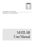
Power up the unit. The liquid handler will initialize and the controller will present Figure 2.1. The pipette
tip will move to determine the zero. If the head does not move, contact your local service representative
for assistance.
HOME
START TO RUN FILE #0
Figure 2.1: The Keypad Controller
Press the START button. The pipette tip will move in the X, Y and Z direction. If the head does not move,
contact your local service representative for assistance.
6
Section 3: System Components
3 SYSTEM COMPONENTS
3.1
Introduction
The WellPro 384 Liquid Handler system includes the following components:
•
•
•
3.2
WellPro Controller (Section 3.2)
WellPro WP384 Liquid Handling Unit (Section 3.3)
WellPro Reagent Containers
WellPro WP384 Controller
The WellPro WP384 Controller includes a keyboard and display which provides the operator with
complete control of all liquid handling operations. The basis of operation is via a user generated method
which includes a series of primary operations. The method can be stored and retrieved as desired.
Each primary operations provides for user control of a given aspect of the operation. Typical operations
include the volumes to transfer, mix, or dispense, the transfer speed, and whether to change tips
between transfers.
3.3
The WellPro WP384 Liquid Handling Unit
The WellPro WP384 Liquid Handling Unit is an electro-mechanical transfer unit that includes a table and a
vertical head assembly. The table accommodates interchangeable templates which position reagent
containers, a magazine with rows of disposable tips, etc. During operation, the table slides back and forth
horizontally to bring the appropriate workstation under the head.
The head assembly consists of three basic parts:
•
•
•
A plunger housing which contains nozzles that press into the tips to form airtight seals
A plunger block which moves up and down to aspirate and deliver samples,
A tip ejector plate which removes used tips. The head assembly slides up and down vertically to
bring the tips to the appropriate height to perform the designated operations.
A 24 channel (tip) air displacement pipetting head is included on the WellPro liquid handler as most
protocols are designed to be performed in the 24 channel mode, but serial dilutions can be performed in
the 16 channel mode to allow for maximum dilution capability with the 384 well plate.
The table assembly drives the plate which holds the well plates and the Microtrof reagent containers.
3.4
The WellPro Reagent Container
The WellPro liquid handler is used with a Microtrof which is a reagent container. The Microtrof container
consists of up to three reservoirs, each of which is used to contain a reagent or solution. In some cases,
fluid from the wells is deposited in the Microtrof.
The WellPro WP384 liquid handler uses templates to position microplates, reagent containers and tip
magazines on the movable table. Two templates are provided as described in Section 1.3.4.
7
Section 4: Establishing a File using the Controller
4 ESTABLISHING A FILE USING THE CONTROLLER
4.1
Introduction
The basis of operation of the WellPro 384 Liquid Handler is the file, which is a set of instructions and
conditions that are used to perform the desired operation. The operator can establish, store and execute
files via the controller module.
The system includes a number of template files that can be used to establish files for actual operation.
To establish a file for a specific operation:
•
•
•
Open the template file that corresponds to the action that you want to perform.
Edit the method to meet the specific requirements of your operation.
Save the file.
As an example; if you want establish a file to be used to add 20 µL to each well in a plate, open File 61
(which is the template file for adding fluid to a plate), edit the file as appropriate and save it using a
different file number (e.g. File 27). When you are ready to run the operation, simply recall the file and
press Start. When a file is executed, the steps are performed in the indicated order.
In this chapter, we describe the keypad controller and explain the general approach to file editing.
Discussion of the individual file templates is presented in Chapters 5-9.
4.2
The Keypad Controller
4.2.1 The Display
When the system is powered up, the display will be as shown in Figure 4.1. The nature of the information
on the display will depend on the status of the system, as described below.
HOME
START to run file #0
Figure 4.1: The Keypad Controller
8
Section 4: Establishing a File using the Controller
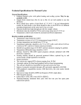
Figure 4.2 The Controller
4.2.2 The Keypad
The controller includes ten alphanumeric keys and nine control keys. The general role of the control keys
is described below. For many keys, the action is dependent on the status of the program.
4.2.3 Clear
1.
Removes information that you have entered on the display before it is entered into the WellPro
controller. This key is most commonly to erase information and start over when you are editing a
file.
2.
Erases an entire user-created file by pressing the File key, the appropriate number keys, the Enter
key, the File key and the Clear key in that order.
4.2.4 Start
1.
Instructs the system to start to carry out the instructions and conditions in the active file.
2.
Restarts a file that has been paused by the user before completion. The file will start where it left
off when it was paused.
9
Section 4: Establishing a File using the Controller
4.2.5 Step
The Step key has several uses:
•
•
•
•
At the start of a file, Step indicates that you want to edit or review the file.
While editing a file, Step is used to indicate that the present setting for the parameter is acceptable,
and you want to see the next parameter.
When the End of File message is displayed, start of the file will be presented for editing or review.
After you have pressed Stop during the execution of a file, the activity indicated in the next line in
the file will be performed.
4.2.6 Stop
The Stop Function has several uses:
•
•
•
•
If you are editing a file, the END OF FILE message will be presented. At this point you have two
choices: If you press Enter and the press Start, the file will be run. If you press Stop again, you will
be able to enter a new file.
If you are running a file, the WellPro liquid handler will pause (stop) the present operation. Once the
WellPro liquid handler has paused, you may either abort the file by pressing the Stop key again), or
go through the file one motion at a time by pressing the Step.
If you are using the Tip Height File (File 70), the Stop key is also used to exit from the file
If you are using the Home-Pump Prime File, the Stop key will stop priming the pump.
4.2.7 Help
1.
Help is normally used to determine the numeric range for a key sequence.
2.
During file editing, the Help key allows you to override the range limits on many parameters.
Normally, the WellPro WP384 Liquid Handler will verify the validity of a parameter (e.g. the transfer
volume) when it is entered by checking against the allowable range of values for the parameter
(which is shown on the display). By pressing the "help" key, the controller in instructed to accept
ANY entered value, subject only to physical limitations of the instrument.
4.2.8 File
A File is a stored set of instruction and conditions which the WellPro WP384 Liquid Handler uses to
perform the desired activity. The user selects the desired file via the alphanumeric keypad and presses
the File followed by the Enter key to load it. 70 files are available.
Files 51 through 70 are pre-programmed in WellPro WP384; and you can modify them to create new files.
Files 1 through 45 are user-storage files. The initial standard files are as follows:
0
61
62
63
70
HOME-PUMP PRIME
PLATE FILLING
SERIAL DILUTION
PLATE TO PLATE
TIP HEIGHT
10
Section 4: Establishing a File using the Controller
4.2.9 Yes/No
The Yes and No keys are used to respond to questions asked by the WellPro controller and tell it whether
you want it to do certain tasks. Each option will be underlined in sequence until you press "step".
4.2.10 Enter
1.
If the Enter key is pressed after an alphanumeric key has been selected, the indicated value is
included in the file.
2.
If the Enter key is pressed at the END OF FILE (RUN), the run will start.
4.3
Entering Data into a File
Each of the template files contains a series of steps that are used to enter the appropriate data for the
task to be performed and you can scroll through the steps via the Step key. When you come to a step
that must be edited, the appropriate selection can be made in one of two ways:
•
The user must enter a numeric value within the range. As an example, the VOLUME IN WELL AT START
step (Figure 4.3) is used to tell the liquid handler how much liquid is in each well before any transfer
has been made. The WellPro uses this number to determine how far down into the wells the tips
should go and also to prevent the instrument from attempting to add more liquid than each well can
hold.
VOLUME IN WELL AT START
(0-350)
0ul
Fig 4.3 The Volume in Well at Start Step
You can set the value of this parameter from 0 to 50 µL in 1 µL increments via the numeric keypad.
After the desired value has been entered, press Enter.
****the range says 350?
•
The user must choose one of a set of discrete values or selections. As an example, the PLATE TYPE
step (Figure 4.4) is used to tell the WellPro liquid handler whether your plate has a FLAT, U-shaped, or
V-shaped bottom. The WellPro liquid handler uses this information to determine the height of the
liquid in each well and thus how far down into the wells the tips should go. One, and only one value is
used for a given plate.
PLATE TYPE
FLAT -U-V-HEIGHT-TUBE
Fig 4.4 The Plate Height Step
To select the desired option, press the YES/↑ or NO/↓ key until it the desired type is highlighted, then
press Enter.
4.4
File 0
File 0 (which is presented when the unit is powered up) is used to initialize the system.
11
Section 5: Plate Filling
5 PLATE FILLING
5.1
Overview
Plate filling refers to the addition of a user specified quantity of liquid to the wells in a plate. The
template for plate filling is File 61, which is used to establish a user file which can be stored and used as
desired (and can be as a template for additional plate filling files).
5.2
Editing a Plate Filling File
When you open file 61 (or any other plate filling file), the opening step is presented and the step
command should be employed to view the file on a screen-by-screen basis. You can change the value of
each parameter to provide the desired program to fill the plates. After a value is entered, press ENTER.
To advance to the next step, press STEP. A detailed discussion of role of each key is presented in Chapter
4.
1.
OPENING STEP
PLATE FILLING
STEP TO EDIT FILE # 61
When File 61 is opened, the OPENING STEP display is presented. If you want to view/edit the file,
press STEP.
2.
PLATE POSITION STEP
PLATE POSITION
1-2
PLATE POSITION is used to whether the plate to be filled is in the FRONT cavity of the template
(Position 1), the second cavity of the template (Position 2) or both. Underline the desired position(s).
3.
VOLUME IN WELL AT START
VOL IN WELL AT START
(0-350)
0ul
VOLUME IN WELL AT START is used to indicate tell how much liquid is in each well before any transfer
has been made. This number is used to determine how far down into the wells the tips should go
and also to prevent the instrument from attempting to add more liquid than each well can hold. This
parameter can be set from 0 to 50 µL in 1 µL increments.
4.
DELIVER FROM
DELIVER FROM
T1 - T2 - T3
DELIVER FROM is used to indicate the MICROTROF reservoir that contains the liquid to be dispensed.
T1, T2, T3 refers to the front, middle, and rear reservoirs of a MICROTROF container. Underline the
desired choice.
12
Section 5: Plate Filling
5.
MIXES IN MICROTROF
MIXES IN MICROTROF
9
3
MIXES IN MICROTROF is used to specify mixing of the MICROTROF contents before an aliquot is taken.
Mixing of a MICROTROF is especially important with cells or other inhomogeneous samples. This
parameter can be set between 0 and 9 (0 indicates no mixing).
6.
MICROTROF MIX VOLUME
MICROTROF MIX VOLUME
(0-200)
50ul
MICROTROF MIX VOLUME is used to indicate how much liquid to aspirate into the tip and dispense
back into the MICROTROF in order to mix the MICROTROF contents. This parameter can be set from 050 in 1 µl increments (0 indicates no mixing). Mix efficiency may vary with MICROTROF volume.
7.
DELIVERY VOLUME
DELIVERY VOLUME
(0-200)
50ul
DELIVERY VOLUME indicates how much solution should be dispensed into each well from the
MICROTROF reservoir. This parameter can be set from 0-50 in 1 µL increments.
8.
MIXES AFTER TRANSFER
MIXES AFTER TRANSFER
(0-9)
2
MIXES AFTER TRANSFER is used to specify the number of mixes after the aliquot has been delivered
to the plate. This parameter may be set from 0-9 in increments of 1 (0 indicates no mix after
transfer).
9.
MIX VOLUME
MIX VOLUME
(0-50)
50ul
MIX VOLUME is used to specify the volume of the aspirate/delivery cycles used to mix the contents
of the well after transfer. The upper limit is calculated as 75% of the transfer (fill) volume. This
parameter can be set from 0 to the upper limit in increments of 1 µL.
10. PLATE TYPE
PLATE TYPE
FLAT-U-V-HEIGHT-TUBE
PLATE TYPE is used to indicate the design of the bottom of the plate. This information is used to
determine the height of the liquid in each well and thus calculate how far down into the wells the
tips should go. If you are not using a standard microplate, select HEIGHT and determine the amount
to raise or lower the tip height by using File 70, the Tip Height File (Section 11). The height
parameter can be set from 100 to 3500 in increments of 1.
13
Section 5: Plate Filling
11. FILL PLATE ROWS
FILL PLATE ROWS
A-B-C-D-E-F-G-H-I-J-K-L-M-N-O-P
FILL PLATE ROWS is used to indicate the rows of the plate to fill and which to leave unfilled. Rows are
designated by letters A through P. To select row A, press YES. The underline will remain and B will be
active (if you do not want to use a row, press NO to advance to the next row). If you want all rows to
be filled, press the STEP key. After the last NO selection has been made, press STEP (i.e. if you want
all rows except for A, press NO for A. The active row will become B. If you press STEP, rows B-P will be
active.
12. MICROTROF VOLUME AT START
MICROTROF VOL AT START
(20-80)
77ml
MICROTROF VOLUME AT START is used to indicate how much liquid is in the reservoir you have chosen
before any liquid has been removed. The system uses the delivery volume and the number of rows
to be filled to calculate the minimum volume needed to run the file and indicates it on the display as
the lower limit. You can set the value of this parameter in 1 mL increments from this lower limit to
20 mL, 60 mL, or 80 mL for the front, middle, and rear reservoirs respectively for the MICROTROF
reservoir.
After the file has been run, the display will update the value to reflect the decreased amount of
liquid in the reservoir.
13. CHANGE TIPS
CHANGE TIPS? YES/NO
YES
CHANGE TIPS is used to indicate if the tips should be removed after the first liquid is dispensed and a
new set of tips from the tip magazine should be placed on the pipette head, thus decreasing
carryover. If you don't want to change tips, then the same tips will be used throughout the entire
operation.
14. LIQUID HANDLING SPEED
LIQ HANDLING SPEEDS
RAPID-MEDIUM-SLOW
LIQUID HANDLING SPEEDS is used to select the rate sample delivery from the tips (rapid, medium, or
slow).
14
Section 5: Plate Filling
15. LINK TO STORED FILE
LINK TO STORED FILE
(0-45, 0=STOP)
0
LINK TO STORED FILE is used to indicate what the system should do after it completes the file it is
currently running.
If you want the system to stop at the end of the file, enter 0.
If you want the system to perform another file after the present file is complete, enter the desired
file number. The LINK TO STORED FILE command permits more efficient operation because you don't
need to start each individual file manually with the "file", "##" A detailed discussion of Linked files is
presented in Section 10.
16. END OF FILE
END OF FILE
RUN-STORE
END OF FILE is used to indicate what the system should do after you have completed the editing of
the file:
•
•
If you select RUN, the file will start.
If you select STORE, the file will be copied into memory (see Section 5.3 for additional
information about storing files).
Note: You can also review the file you have just made by continuing to press the STEP key.
17. ENTER FIRST TIP ROW
ENTER FIRST TIP ROW
(A-P)
P
15
Section 5: Plate Filling
5.3
Storing/Overwriting the File
To store a new file:
1.
At the END OF FILE statement (item p, Section 5.2), select STORE. The display will appear as shown
below.
FILE STORE
ENTER USER # ____
2.
Enter your user number or project number (this number is provided for reference only and does not
affect the use of the system), then press ENTER. The display will indicate:
FILE STORE
ENTER FILE #XX
where xx is the file number assigned by the system (it will be the lowest unoccupied file). If you
want to assign a different number, enter it.
3.
Press ENTER. The display will present:
YES TO STORE
USER #zzzz FILE #XX
4.
5.4
Press YES to accept the assignment.
Running a Plate Filling File
When you are ready to run a Plate Filling file:
1.
Select the desired file
2.
Press START
If the MICROTROF does not contain the required amount of liquid to perform the desired operation, the
message PLEASE FILL MICROTROF will appear on the screen. This prompt allows you to simply enter the
volume you are adding to the MICROTROF reservoir without requiring you to step back through each of
the file's parameters.
At the conclusion of the operation, the system will stop or proceed to the file that is linked to it.
16
Section 5: Plate Filling
5.5
Sample Plate Filling Experiment
File 61: Plate Filling
The following example will show you how to perform a plate filling operation using a 24 across template.
The plate will be in position 1.
Each well of the plate will be pre-filled with 25 µL of solution. There will be four mixes in each well after
every transfer.
1.
Fill an empty plate with 25 µL of diluent.
2.
Place a "24 across" template on the table.
3.
Place the magazine of tips in the back cavity of the template.
4.
Place the plate in the front cavity of the template with samples.
5.
Press "file", "61", and then "enter" to access File 612.
6.
Edit the file using the following keystrokes:
17
Section 5: Plate Filling
Display Before Editing
Keystrokes
Display After Editing
PLATE FILLING
STEP TO EDIT FILE #61
STEP
-
PLATE POSITION STEP
1
1
VOL IN WELL AT START
(0-50)
25 ul
25; ENTER
VOL IN WELL AT START
(0-50)
25 ul
DELIVER FROM
T1
T2
T1: ENTER
DELIVER FROM
T1
T3
MIXES IN MICROTROF
9
3
5, ENTER
5
MICROTROF MIX VOLUME
(0-200)
50ul
STEP
DELIVERY VOLUME
0-200 50
T3
MIXES IN MICROTROF
MICROTROF MIX VOLUME
3 ul
(0-3)
DELIVERY VOLUME
75
MIXES AFTER TRANSFER
T2
4
0-200
75
MIXES AFTER TRANSFER
MIX VOLUME
0-50
50
25
MIX VOLUME
25
PLATE TYPE
FLAT-U-V-HEIGHT-TUBE
U
PLATE TYPE
FLAT-U-V-HEIGHT-TUBE
FILL PLATE ROWS
A-B-C-D-E-F-G-H-I-J-K-L-M-N-O-P
C
FILL PLATE ROWS
A-B-C-D-E-F-G-H-I-J-K-L-M-N-O-P
MICROTROF VOL AT START
(20-80)
77 mL
70
MICROTROF VOL AT START
20-80 70
CHANGE TIPS
YES/NO YES
YES
CHANGE TIPS
YES/NO YES
LIQ HANDLING SPEEDS
RAPID-MEDIUM-SLOW
LINK TO STORED FILE
(0-45, 0=STOP)
LIQ HANDLING SPEEDS
RAPID-MEDIUM-SLOW
0
0
LINK TO STORED FILE
(0-45, 0=STOP)
END OF FILE
RUN-STORE
18
0
Section 6: Serial Dilution
6 SERIAL DILUTION
6.1
Overview
Serial Dilution is the progressive dilution and redilution of a liquid. In this process, a sample is added to a
diluent and the two are mixed. An aliquot is then removed for addition to the next diluent-containing
well. This sequence is repeated until the desired number of dilutions have been obtained ("serial
dilutions"). As an example, if equal volumes of sample and diluent were mixed during each step of the
series, the sample concentration would be 1:2, 1:4, 1:8, 1:16, 1:32, and so on in sequential rows.
The template for Serial Dilution is File 62. This file can be used as a template to establish a user file which
can be stored and used as desired (and it can be as a template for additional serial dilution files).
6.2
Editing a Serial Dilution File
When you open File 62 (or any other Serial Dilution file), the opening step is presented and the step
command should be selected to view the file on a screen-by-screen basis. You can change the value of
each parameter as desired to provide the desired program to fill the plates. After a value is entered,
press ENTER. To advance to the next step press STEP. A detailed discussion of role of each key is
presented in Chapter 4.
1.
OPENING STEP
SERIAL DILUTION
STEP TO EDIT FILE # 62
When File 62 is opened, the OPENING STEP display is presented. If you want to view/edit the file,
press STEP.
2.
VOL IN WELL AT START STEP
VOL IN WELL AT START
(0-350)
20 ul
VOLUME IN WELL AT START is used to tell the system how much diluent is in each well before any
transfer has been made. This parameter does not pertain to the first row, which contains the
sample. The system uses this number to determine how far down into the wells the tips should go,
and also to prevent the instrument from attempting to withdraw more sample than is actually
present. This parameter can be set from 0 to 50 µL in 1 µL increments.
*****screen says 0-350 but text says 50
3.
TRANSFER VOLUME
TRANSFER VOLUME
(0-100)
5 ul
TRANSFER VOLUME indicates how much sample should be withdrawn from the original well for
transfer to the new well during a serial dilution. This parameter can be set from 0 to 50 µL in 1 µL
increments. A transfer volume of 0 may be used if you wish to simply mix the contents of the well.
19
Section 6: Serial Dilution
4.
MIXES BEFORE TRANSFER
MIXES BEFORE TRANSFER
(0-9)
3
MIXES BEFORE TRANSFER is used to indicate the number of aspiration/delivery cycles that should be
performed before transferring a sample. As an example, if you are diluting cells which may settle,
the MIX BEFORE TRANSFER step might be used to agitate them back into suspension before transfer
by mixing. This parameter can be set from 0 to 9 (0 indicates no mixing).
5.
MIX VOLUME
MIX VOLUME
(0-75)
5ul
MIX VOLUME is used to tell the system how much solution should be used in the Mix step. Typically
this volume is set to 50% of the total volume in the well to be mixed, but will be more or less
depending on the application (when mixing cells, it may be desirable to use a lower percentage of the
total volume). The value of this parameter may not exceed 75% of the total volume in the well you
are mixing. The system will automatically calculate this amount and indicate it on the display as the
upper limit in the range. This parameter can be set in 1 µL increments from 0 µL to the upper limit.
6.
CHANGE TIPS
CHANGE TIPS? YES/NO
YES
CHANGE TIPS is used to indicate if the tips should be removed after the first liquid is dispensed and a
new set of tips from the tip magazine should be placed on the pipette head, thus decreasing
carryover. If you don't want to change tips, then the same tips will be used throughout the entire
operation.
7.
PLATE TYPE
PLATE TYPE
FLAT-U-V-HEIGHT-TUBE
PLATE TYPE is used to indicate the design of the bottom of the plate. This information is used to
determine the height of the liquid in each well and thus calculate how far down into the wells the
tips should go. If you are not using a standard microplate, select HEIGHT and determine the amount
to raise or lower the tip height by using File 70, the Tip Height File (Section x.xx). The height
parameter can be set from 100 to 3500 in increments of 1.
8.
PLATE ORIENTATION
PLATE ORIENTATION
24-16 WELLS ACROSS
PLATE ORIENTATION is used to indicate how the plate is positioned. The value that is selected
indicates the number of wells that will be under the pipette tips at one time.
20
Section 6: Serial Dilution
9.
ROWS TO DILUTE
ROWS TO DILUTE
A-B-C-D-E-F-G-H-I-J-K-L-M-N-O-P
ROWS TO DILUTE is used to indicate the rows of the plate are to be included in the serial dilution.
Rows are designated by letters A through P (back to front) in the "24 across" configuration and 1
through 16 in the "16 across" configuration. To select row A, press YES. The underline will remain and
B will be active (if you do not want to use a row, press NO to advance to the next row). If you want all
rows to be filled, press the STEP key. After the last NO selection has been made, press STEP (i.e. if
you want all rows except for A, press NO for A. The active row will become B. If you press STEP, rows
B-P will be active.
10. EMPTY LAST ROW TO
EMPTY LAST ROW TO
OFF-1ST ROW-MAG-MICROTROF3
EMPTY LAST ROW TO is used to tell the system where to place the extra volume of liquid transferred
into the last row of wells after a serial dilution.
1.
If you select OFF, the extra liquid will be left in the last row of wells.
2.
If you select 1ST ROW, the extra liquid will be removed from the last row of wells and return it to
the first row of wells you chose in ROWS TO DILUTE.
3.
If you select MAG, the system will remove the extra liquid and discard it into the tip magazine.
4.
If you select MICROTROF3, the system will remove the extra liquid and discard it into the rear
reservoir of a MICROTROF container located in the P2 cavity of the template.
Note: Note: MICROTROF3 will appear on the display only when the 24 wells across PLATE
ORIENTATION is selected.
11. LIQUID HANDLING SPEED
LIQ HANDLING SPEEDS
RAPID-MEDIUM-SLOW
LIQUID HANDLING SPEEDS is used to select the rate sample delivery from the tips (rapid, medium, or
slow).
21
Section 6: Serial Dilution
12. LINK TO STORED FILE
LINK TO STORED FILE
(0-45, 0=STOP)
0
LINK TO STORED FILE is used to indicate what the system should do after it completes the file it is
currently running.
If you want the system to stop at the end of the file, enter 0.
If you want the system to perform another file after the present file is complete, enter the desired
file number. The LINK TO STORED FILE command permits more efficient operation because you don't
need to start each individual file manually with the "file", "##" A detailed discussion of Linked files is
presented in Section 10.
13. END OF FILE
END OF FILE
RUN-STORE
END OF FILE is used to indicate what the system should do after you have completed the editing of
the file.
If you select RUN, the file will start and step 14 will be presented.
If you select STORE, the file will be copied into memory (see Section 6.3 for additional information
about storing files).
14. ENTER FIRST TIP ROW
ENTER FIRST TIP ROW
(A-P)
P
ENTER FIRST TIP ROW is used to specify which row of tips to use. Rows of the tip magazine are
designated by letters A through P (back to front).
22
Section 6: Serial Dilution
6.3
Storing/Overwriting the File
To store a new file:
1.
At the END OF FILE statement (item p, Section 5.2), select STORE. The display will appear as shown
below.
FILE STORE
ENTER USER # _____
2.
Enter your user number or project number (this number is provided for reference only and does not
affect the use of the system), then press ENTER. The display will indicate:
FILE STORE
ENTER FILE #XX
Where xx is the file number assigned by the system, which will be the lowest unoccupied file. If you
want to assign a different number, enter it.
3.
Press ENTER. The display will present:
YES TO STORE
USER #zzzz FILE #XX
4.
6.4
Press YES to accept the assignment.
Running a Serial Dilution File
When you are ready to run a Serial Dilution:
1.
Select the desired file.
2.
Press START.
If the MICROTROF does not contain the required amount of liquid to perform the desired operation, the
message PLEASE FILL MICROTROF will appear on the screen. This prompt allows you to simply enter the
volume you are adding to the MICROTROF reservoir without requiring you to step back through each of
the file's parameters.
At the conclusion of the operation, the system will stop or proceed to the file that is linked to it.
23
Section 6: Serial Dilution
6.5
Sample Serial Dilution Experiment
File 62: Serial Dilution: 1:2 Ratio
The following example will show you how to perform a simple 1:2, 1:4, 1:8, 1:16, etc. serial dilution on 5 µL
samples in an "16 across" microplate. Each well of the plate will be pre-filled with 25 µL of solution.
There will be four mixes in each well after every transfer.
1.
Fill an empty plate with 25 µL of diluent.
2.
Place a "16 across" template on the table.
3.
Place the magazine of tips in the back cavity of the template.
4.
Manually pipette 50 µL samples into row 1 of the plate. Use water in this example.
5.
Place the plate in the front cavity of the template with samples.
6.
Press "file", "62", and then "enter" to access File 62.
7.
Edit the file using the following keystrokes:
24
Section 6: Serial Dilution
Display Before Editing
Keystrokes
Display After Editing
SERIAL DILUTION
STEP TO EDIT FILE #62
STEP
-
VOL IN WELL AT START
(0-50)
25 ul
25; ENTER
VOL IN WELL AT START
(0-50)
TRANSFER VOLUME
(0-50)
5 ul
MIXES BEFORE TRANSFER
(0-9)
3
MIX AFTER TRANSFER
(0-9)
3
MIX VOLUME
(0-3)
3 ul
PLATE TYPE
FLAT-U-V-HEIGHT-TUBE
TRANSFER VOLUME
(0-50)
STEP
STEP
MIX AFTER TRANSFER
(0-9)
3
MIX VOLUME
(0-3)
STEP
STEP
STEP
5 ul
MIXES BEFORE TRANSFER
(0-9)
3
STEP
CHANGE TIPS?
YES-NO
25 ul
YES-NO
NO;
3 ul
CHANGE TIPS?
PLATE TYPE
FLAT-U-V-HEIGHT-TUBE
PLATE ORIENTATION
24-16 WELLS ACROSS
NO;
STEP
PLATE ORIENTATION
24-16 WELLS ACROSS
DILUTE ROWS 1-2-34-5-6-7-8-9-10-11-12
13-14-15-16-17-18-19
-20-21-22-23-24
STEP
DILUTE ROWS 1-2-34-5-6-7-8-9-10-11-1213-14-15-16-17-18-19
20-21-22-23-24
EMPTY LAST ROW TO
OFF-1ST ROW-MAG-TROF3
STEP
EMPTY LAST ROW TO
OFF-1ST ROW-MAG-TROF3
LIQ HANDLING SPEEDS
RAPID-MEDIUM-SLOW
STEP
LIQ HANDLING SPEEDS
RAPID-MEDIUM-SLOW
LINK TO STORED FILE
(0-45, 0=STOP) 0
STEP
LINK TO STORED FILE
(0-45, 0=STOP) 0
END OF FILE
RUN-STORE
ENTER
-
SERIAL DILUTION
START TO RUN FILE #62
START
-
Serial dilutions can be very cumbersome and time consuming when performed manually. The WellPro
liquid handler has the capability to perform very complex serial dilution sequences. As you gain
familiarity with the WellPro liquid handler and especially the powerful FILE LINKING features, experiment
with the range of possible sequences to customize your own complex serial dilution files.
25
Section 7: Plate to Plate Transfer
7 PLATE TO PLATE TRANSFER
7.1
Overview
Transferring an aliquot of sample from one plate to another is called "plate-to-plate" transfer or "replica
plating." This technique allows for transfer of samples in a SOURCE plate to a RECEIVER plate for assay,
culture, etc.
The steps required to perform the plate transfer are:
1.
Aspirate sample from source plate.
2.
Deliver sample to receiver plate.
3.
Replace used tip with fresh one and proceed to next sample row, etc.
The template for Plate to Plate Transfer is File 63, which is used as a template to establish a user file
which can be stored and used as desired (and it can be as a template for additional serial dilution files).
7.2
Types of Plate to Plate Transfer
There are two general types of Plate to Plate Transfer:
1.
transfer any single row in one plate to any other single row in another plate.
2.
transfer any single row in one plate to two or more rows in another plate.
The program allows you to specify the direction of the transfer. The default direction is from plate 2 to
plate 1, but the system also allows you to transfer from plate 1 to plate 2, so that either plate can be
used as the DESTINATION plate. As examples, you can transfer from row A of plate 1 to row B of plate 2
or you can transfer from row A of plate 2 to rows A, B, and C of plate 1. This enables you to set up an
assay plate to do duplicates, triplicates, etc.
The TRANSFER MODE/DIRECTION is a feature that is especially useful when it is combined with FILE LINK
because it allows you to transfer duplicate samples from the rows of one plate to another plate. Thus,
using these functions in combination makes it possible to transfer from row A of plate 1 to rows A and B
of plate 2, then automatically continue with another file which transfers from row B of plate 1 to rows C
and D of plate 2, and so on.
TRANSFER MODE/DIRECTION also allows you to use a 384 well plate as a reagent MICROTROF to deliver
multiple reagents to a single assay plate. You can place the same or different reagents in each of the 24
columns, and/or each of the 16 rows of the source plate. These reagents can be delivered to specified
rows on the destination plate. This arrangement minimizes reagent waste.
When you use TRANSFER MODE/DIRECTION feature with the TUBE HANDLING feature option, you can carry
out transfers from larger containers such as micro test tubes or segmented troughs and use them as
reagent containers. Using the "help" key enables you to extend the acceptable range for TRANSFER
VOLUME and VOLUME IN WELL AT START, so you can make full use of the larger volume capacity of these
containers
26
Section 7: Plate to Plate Transfer
7.3
Editing a Plate to Plate Transfer File
When you open file 63 (or any other Serial Dilution file), the opening step is presented and the step
command should be selected to view the file on a screen-by-screen basis. You can change the value of
each parameter as desired to provide the desired program to fill the plates. After a value is entered,
press ENTER. To advance to the next step press STEP. A detailed discussion of role of each key is
presented in Chapter 4.
1.
OPENING STEP
PLATE TO PLATE
STEP TO EDIT FILE #63
When File 63 is opened, the OPENING STEP display is presented. If you want to view/edit the file,
press STEP.
2.
TRANSFER DIRECTION
TRANSFER DIRECTION
P2 to P1 - P1 to P2
TRANSFER DIRECTION is used to indicate whether the system should transfer from plate 2 to plate 1
or from plate 1 to plate 2 (i.e. either plate 1 (the plate in the front cavity of the template) or plate 2
(the plate in the middle cavity) can be used as the source plate.
3.
VOL IN WELL PLATE 1
VOL IN WELL PLATE 1
(0-50)
0 ul
VOLUME IN WELL PLATE 1 is used to indicate how much liquid is in each well of plate 1. The system
uses this value to determine how far down into the wells the tips should go and also to prevent
exceeding the volume capacity of the wells. This parameter can be set from 0 to 50 µL in 1 µL
increments.
4.
VOL IN WELL PLATE 2
VOL IN WELL PLATE 2
(0-50)
50 ul
VOLUME IN WELL PLATE 2 is used to indicate how much liquid is in each well of plate 2. The system
uses this value to determine how far down into the wells the tips should go and also to prevent
exceeding the volume capacity of the wells. This parameter can be set from 0 to 50 µL in 1 µL
increments.
5.
TRANSFER MODE
TRANSFER MODE
1 TO 1-1 TO SEVERAL
TRANSFER MODE is used to tell the system whether to transfer one row of plate 1 to the
corresponding row of plate 2, or to transfer one row of plate 1 to several different or multiple rows
of plate 2.
27
Section 7: Plate to Plate Transfer
6.
TRANSFER VOLUME
TRANSFER VOLUME
(0-50)
25 ul
TRANSFER VOLUME is used to tell the system how much sample to withdraw from a source well for
transfer to a new well during a plate transfer. This parameter can be set from 0 to 50 µL in 1 µL
increments. The system calculates the maximum TRANSFER VOLUME for the row by dividing the
VOLUME IN WELL AT START by the number of transfers specified for that row.
7.
MIXES BEFORE TRANSFER
MIXES BEFORE TRANSFER
(0-9)
0
MIXES BEFORE TRANSFER is used to indicate the number of aspiration/delivery cycles that should be
performed before transferring a sample. For example, when you are diluting cells which may settle,
you should agitate them back into suspension before transfer by mixing. This parameter can be set
from 0 to 9 (0 indicates no mixing).
8.
MIXES AFTER TRANSFER
MIXES AFTER TRANSFER
(0-9)
0
MIXES AFTER TRANSFER is used to indicate the number of aspiration/delivery cycles that should be
performed after transferring a sample. For example, when you are diluting cells which may settle,
you should agitate them back into suspension after transfer by mixing. This parameter can be set
from 0 to 9 (0 indicates no mixing).
9.
MIX VOLUME
MIX VOLUME
(0-25)
25 ul
MIX VOLUME is used to tell the system how much solution should be used in the Mix step. Typically
this volume is set to 50% of the total volume in the well to be mixed, but will be more or less
depending on the application. For example, when mixing cells it may be desirable to use a lower
percentage of the total volume. The value of this parameter may not exceed 75% of the total
volume in the well you are mixing. The system will automatically calculate this amount and indicate
it on the display as the upper limit in the range. This parameter can be set in 1 µL increments from 0
µL to the upper limit.
10. CHANGE TIPS
CHANGE TIPS?
YES-NO
CHANGE TIPS is used to indicate if the tips should be removed after the first liquid is dispensed and a
new set of tips from the tip magazine should be placed on the pipette head, thus decreasing
carryover. If you don't want to change tips, then the same tips will be used throughout the entire
operation.
28
Section 7: Plate to Plate Transfer
11. PLATE 1 TYPE
PLATE 1 TYPE
FLAT-U-V-HEIGHT-TUBE
PLATE 1 TYPE is used to indicate the design of the bottom of plate 1. This information is used to
determine the height of the liquid in each well and thus calculate how far down into the wells the
tips should go. If you are not using a standard microplate, select HEIGHT and determine the amount
to raise or lower the tip height by using File 70, the Tip Height File (Section x.xx). The height
parameter can be set from 100 to 3500 in increments of 1.
12. PLATE 2 TYPE
PLATE 2 TYPE
FLAT-U-V-HEIGHT-TUBE
PLATE 2 TYPE is used to indicate the design of the bottom of plate 2. This information is used to
determine the height of the liquid in each well and thus calculate how far down into the wells the
tips should go. If you are not using a standard microplate, select HEIGHT and determine the amount
to raise or lower the tip height by using File 70, the Tip Height File (Section x.xx). The height
parameter can be set from 100 to 3500 in increments of 1.
13. SOURCE ROW
SOURCE ROW
A-B-C-D-E-F-G-H-I-J-K-L-M-N-O-P
SOURCE ROW is used to indicate which row of the SOURCE plate is used to withdraw samples from.
This parameter only appears if the "1 to SEVERAL" mode is selected in this file. In that instance, the
SOURCE row specified acts as the single source row for transfer to several receiving or DESTINATION
rows.
14. TRANSFER ROW
TRANSFER ROW
A-B-C-D-E-F-G-H-I-J-K-L-M-N-O-P
TRANSFER ROW is used to indicate which row of the TRANSFER plate is used to place liquid in during
transfer. This parameter only appears if the "1 to SEVERAL" mode is selected in this file. In that
instance, the SOURCE row specified acts as the single source row for transfer to several receiving or
DESTINATION rows.
15. DESTINATION ROWS
DESTINATION ROWS
A-B-C-D-E-F-G-H-I-J-K-L-M-N-O-P
DESTINATION ROW is used to indicate which row of the DESTINATION plate is used to place liquid in
during transfer. This parameter only appears if the "1 to SEVERAL" mode is selected in this file. In
that instance, the SOURCE row specified acts as the single source row for transfer to several
receiving or DESTINATION rows.
29
Section 7: Plate to Plate Transfer
16. LIQ HANDLING SPEEDS
LIQ HANDLING SPEEDS
RAPID-MEDIUM-SLOW
LIQ HANDLING SPEEDS is used to select the rate of sample delivery from the tips (rapid, medium, or
slow).
17. LINK TO STORED FILE
LINK TO STORED FILE
(0-45, 0=STOP)
0
LINK TO STORED FILE is used to indicate what the system should do after it completes the file it is
currently running.
If you want the system to stop at the end of the file, enter 0.
If you want the system to perform another file after the present file is complete, enter the desired
file number. The LINK TO STORED FILE command permits more efficient operation because you don't
need to start each individual file manually with the "file", "##" A detailed discussion of Linked files is
presented in Section 10.
18. END OF FILE
END OF FILE
RUN-STORE
END OF FILE is used to indicate what the system should do after you have completed the editing of
the file:
If you select RUN, the file will start.
If you select STORE, the file will be copied into memory (see Section 6.3 for additional information
about storing files).
19. ENTER FIRST TIP ROW
ENTER FIRST TIP ROW
(A-P)
P
ENTER FIRST TIP ROW is used to specify which row of tips to use. Rows of the tip magazine are
designated by letters A through P (back to front).
30
Section 7: Plate to Plate Transfer
7.4
Storing/Overwriting the File
To store a new file:
1.
At the END OF FILE statement (item p, Section 5.2), select STORE. The display will appear as shown
below.
FILE STORE
ENTER USER # _____
2.
Enter your user number or project number (this number is provided for reference only and does not
affect the use of the system, then press ENTER. The display will indicate:
FILE STORE
ENTER FILE #XX
Where xx is the file number assigned by the system, which will be the lowest unoccupied file. If you
want to assign a different number, enter it.
3.
Press ENTER. The display will present:
YES TO STORE
USER #zzzz FILE #XX
4.
7.5
Press YES to accept the assignment.
Running a Plate to Plate Transfer
When you are ready to run a plate to plate transfer:
1.
Select the desired file.
2.
Press START.
If the MICROTROF does not contain the required amount of liquid to perform the desired operation, the
message PLEASE FILL MICROTROF will appear on the screen. This prompt allows you to simply enter the
volume you are adding to the MICROTROF reservoir without requiring you to step back through each of
the file's parameters.
At the conclusion of the operation, the system will stop or proceed to the file that is linked to it.
31
Section 7: Plate to Plate Transfer
7.6
Sample Serial Dilution Experiments
File 63: Plate to Plate Transfer
The following example will show you how to perform a simple transfer of 30 µL of a simulated cell
suspension from plate 2 to plate 1 which contains no liquid in its wells prior to transfer. There will be
four 30 µL medium-speed mixes in each well before solution is transferred, as might be the case when
you want to gently agitate cells into suspension before transferring them. You will be using flatbottomed plates.
1.
Place a "24 across" template on the table.
2.
Place a magazine of tips in the back cavity of the template.
3.
For demonstration purposes, manually pipette 50 µL of water into each of the 384 wells of plate #2.
4.
Place the plate in the middle cavity of the template.
5.
Place an empty plate in the front cavity of the template.
6.
Press "file", "63", and then "enter" to access File 63.
7.
Edit the file using the following keystrokes:
32
Section 7: Plate to Plate Transfer
Display Before Editing
Keystrokes
Display After Editing
PLATE-TO-PLATE
STEP TO EDIT FILE #63
STEP
-
TRANSFER DIRECTION
P2 TO P1 - P1 TO P2
STEP
TRANSFER DIRECTION
P2 TO P1 - P1 TO P2
VOL IN WELL PLATE 1
(0-50)
0 ul
STEP
VOL IN WELL PLATE 1
(0-50)
0 ul
STEP
VOL IN WELL PLATE 2
(0-50)
50 ul
VOL IN WELL PLATE 2
(0-50)
50 ul
TRANSFER MODE
1 TO 1-TO SEVERAL
TRANSFER VOLUME
(0-50)
TRANSFER MODE
1 TO 1-TO SEVERAL
STEP
70; ENTER
30ul
TRANSFER VOLUME
(0-50)
30ul
MIXES BEFORE TRANSFER
(0-9)
0
4; ENTER
MIXES BEFORE TRANSFER
(0-9)
4
MIXES AFTER TRANSFER
(0-9)
0
STEP
MIXES AFTER TRANSFER
(0-9)
0
MIX VOLUME
(0-22)
22; ENTER
22 ul
MIX VOLUME
(0-22 ul)
CHANGE TIPS?
YES-NO
STEP
PLATE 1 TYPE
FLAT-U-V-HEIGHT-TUBE
STEP
PLATE 1 TYPE
FLAT-U-V-HEIGHT-TUBE
PLATE 2 TYPE
FLAT-U-V-HEIGHT-TUBE
STEP
PLATE 2 TYPE
FLAT-U-V-HEIGHT-TUBE
YES-NO
22 ul
CHANGE TIPS?
TRANSFER ROWS
A-B-C-D-E-F-G-H
I-J-K-L-M-N-O-P
STEP
TRANSFER ROWS
A-B-C-D-E-F-G-H
I-J-K-L-M-N-O-P
LIQ HANDLING SPEEDS
RAPID-MEDIUM-SLOW
NO; STEP
LIQ HANDLING SPEEDS
RAPID-MEDIUM-SLOW
LINK TO STORED FILE
(0-45, 0-STOP)
0
STEP
LINK TO STORED FILE
(0-45, 0-STOP)
0
END OF FILE
RUN-STORE
ENTER
-
PLATE TO PLATE
START TO RUN FILE #63
START
-
33
Section 7: Plate to Plate Transfer
File 63: Plate to Plate Transfer Mode and Direction
The following example will show you how to use the TRANSFER MODE capability in combination with File
63: Plate-to-Plate Transfer to transfer 35 µL of water, simulating sample. The WellPro liquid handler
allows you to specify the direction of the transfer. You can designate either plate as the SOURCE or the
DESTINATION plate.
In this case the transfer will be from row B of plate 1 to rows C and D of plate 2.
1.
Place a "24 across" template on the table.
2.
Place a magazine of tips in the back cavity of the template.
3.
Place the source plate into the front cavity of the template. This will be the source plate.
4.
Place an empty plate in the middle cavity of the template. This will be the destination plate, plate
#2.
5.
Press "file", "63", and then "enter" to access File 63.
6.
Edit the file using the following keystrokes:
Display Before Editing
Keystrokes
Display After Editing
PLATE TO PLATE
STEP TO EDIT FILE #63
STEP
-
TRANSFER DIRECTION
P2 TO P1 - P1 TO P2
NO;STEP
VOL IN WELL PLATE 1
(0-50)
50 ul
VOL IN WELL PLATE 2
(0-50)
0 ul
TRANSFER MODE
1 TO 1-1 TO SEVERAL
TRANSFER DIRECTION
P2 TO P1 - P1 TO P2
STEP
VOL IN WELL PLATE 1
(0-50)
50 ul
STEP
VOL IN WELL PLATE 2
(0-50)
0 ul
TRANSFER MODE
1 TO 1- 1 TO SEVERAL
STEP
SOURCE ROW
A-B-C-D-E-F-G-H
STEP
NO;
SOURCE ROW
A-B-C-D-E-F-G-H
DESTINATION ROWS
A-B-C-D-E-F-G-H
NO; NO; YES; YES;
NO; NO; NO; NO; STEP
- -C-D- - - -
DESTINATION ROWS
Note: In the next step, the WellPro controller automatically calculates the acceptable range of
the TRANSFER VOLUME by dividing the VOL IN WELL PLATE 1 (50 µl) by the number of rows a
transfer will be made to (two rows, C and D). The maximum acceptable volume for the transfer
is therefore 25 µl.
34
Section 7: Plate to Plate Transfer
Display Before Editing
Keystrokes
TRANSFER VOLUME
(0-50)
50 ul
Display After Editing
25; ENTER
TRANSFER VOLUME
(0-50)
25 ul
MIXES BEFORE TRANSFER
(0-9)
0
STEP
MIXES BEFORE TRANSFER
(0-9)
0
MIXES AFTER TRANSFER
(0-9)
0
STEP
MIXES AFTER TRANSFER
(0-9)
0
CHANGE TIPS?
YES-NO
STEP
PLATE 1 TYPE
FLAT-U-V-HEIGHT-TUBE
STEP
PLATE 1 TYPE
FLAT-U-V-HEIGHT-TUBE
PLATE 2 TYPE
FLAT-U-V-HEIGHT-TUBE
STEP
PLATE 2 TYPE
FLAT-U-V-HEIGHT-TUBE
LIQ HANDLING SPEEDS
RAPID-MEDIUM-SLOW
YES-NO
STEP
CHANGE TIPS?
LIQ HANDLING SPEEDS
RAPID-MEDIUM-SLOW
LINK TO STORED FILE
(0-45, 0=STOP) 0
STEP
LINK TO STORED FILE
(0-45, 0=STOP) 0
END OF FILE
RUN-STORE
ENTER
-
PLATE TO PLATE
START TO RUN FILE #63
START
-
Note: The WellPro liquid handler allows you to create and store multiple versions of File 63: Plateto-Plate Transfer, so as to transfer from row A of plate 1 to rows A and B of plate 2, from row B
to rows C and D, from row C to rows E and F, from row D to rows G and H, and then link these
files together. The result is that you can conveniently transfer from the rows of one plate to
duplicate rows of another plate for assay, using a single "start" keystroke. Details on file linking
are provided in Section 10.
35
Section 8: Empting a Plate
8 EMPTYING A PLATE
8.1
Overview
The WellPro liquid handler can remove all or part of the solution in a plate and replace it with another
solution which is delivered from a MICROTROF reservoir.
The steps that the WellPro liquid handler uses to empty a plate.are:
1.
Aspirate sample from plate.
2.
Deliver to "T3" waste reservoir.
The template for Emptying a plate is File 64, which is used as a template to establish a user file that can
be stored and used as desired (and it can be used as a template for additional Emptying a plate files
Note: This file is designed to make rapid exchanges of culture media, reagents, diluents, etc.
within a single plate. For refilling with a new reagent, link to an edited FILE # 61, plate fill file.
8.2
Editing an Emptying a Plate File
When you open file 64 (or any other Serial Dilution file) the opening step is presented and the step
command should be selected to view the file on a screen-by-screen basis. You can change the value of
each parameter as desired to provide the desired program to fill the plates. After a value is entered,
press ENTER. To advance to the next step press STEP. A detailed discussion of role of each key is
presented in Chapter 4.
1.
OPENING STEP
PLATE EMPTY
STEP TO EDIT FILE # 64
When File 64 is opened, the OPENING STEP display is presented. If you want to view/edit the file, press STEP.
2.
VOL IN WELL AT START
VOL IN WELL AT START
(0-50)
50 ul
VOLUME IN WELL AT START is used to how much liquid is in each well before any solution has been
removed. The system uses this number to determine how far down into the wells the tips should go
and also to prevent the instrument from attempting to withdraw “present”. This parameter can be
set from 0 to 50 µL in 1 µL increments.
36
Section 8: Empting a Plate
3.
VOLUME TO EMPTY
VOLUME TO EMPTY
(0-50)
50 ul
VOLUME TO EMPTY: is used to indicate how much liquid to remove from each well and transfer to
the waste container, a reservoir or the MICROTROF container. This parameter can be set from 0 to 50
µL in 1 µL increments.
4.
WASTE TO MICROTROF
WASTE TO MICROTROF
T1-T2-T3
WASTE TO MICROTROF is used to indicate which reservoir of the MICROTROF container to deliver its waste
solution to. This parameter can be set to T1, T2, or T3, which indicate respectively the front, middle, and
rear reservoirs.
5.
CHANGE TIPS
CHANGE TIPS
YES-NO
CHANGE TIPS is used to indicate whether you want it to get new tips from the tip magazine during
the waste removal, thus decreasing carryover. If you don't want to change tips, the system will use
the same tips for the whole plate.
6.
PLATE TYPE
PLATE TYPE
FLAT-U-V-HEIGHT-TUBE
PLATE TYPE is used to indicate the design of the bottom of the plate. This information is used to
determine the height of the liquid in each well and thus calculate how far down into the wells the
tips should go. If you are not using a standard microplate, select HEIGHT and determine the amount
to raise or lower the tip height by using File 70, the Tip Height File (Section 10). The height
parameter can be set " from 100 to 3500 in increments of 1.
7.
MIXES BEFORE EMPTY
MIXES BEFORE EMPTY
(0-9)
0
MIXES BEFORE EMPTY is used to tell the system how many mixes (aspiration/delivery cycles) should be
performed during the mixing process before waste removal. You can set the value of this parameter
from 0 to 9 mixes in increments of 1. The numeral 0 indicates no mixing
37
Section 8: Empting a Plate
8.
ROWS TO EMPTY
ROWS TO EMPTY
A-B-C-D-E-F-G-H-I-J-K-L-M-N-O-P
ROWS TO EMPTY is used to indicate the rows of the plate to empty and which to leave illed. Rows are
designated by letters A through P. To select row A, press YES. The underline will remain and B will be
active (if you do not want to use a row, press NO to advance to the next row). If you want all rows to
be emptied, press the STEP key. After the last NO selection has been made, press STEP (i.e. if you want
all rows except for A, press NO for A. The active row will become B. If you press STEP, rows B-P will be
active.
9.
LIQUID HANDLING SPEEDS
LIQ HANDLING SPEEDS
RAPID-MEDIUM-SLOW
LIQUID HANDLING SPEEDS is used to select the rate sample withdrawal by the tips (rapid, medium, or
slow).
10. LINK TO STORED FILE
LINK TO STORED FILE
(0-45, 0=STOP)
0
LINK TO STORED FILE is used to indicate what the system should do after it completes the file it is
currently running.
If you want the system to stop at the end of the file, enter 0.
If you want the system to perform another file after the present file is complete, enter the desired
file number. The LINK TO STORED FILE command permits more efficient operation because you don't
need to start each individual file manually with the "file", "##" A detailed discussion of Linked files is
presented in Section 10.
11. END OF FILE
END OF FILE
RUN-STORE
END OF FILE is used to indicate what the system should do after you have completed the editing of
the file.
If you select RUN, the file will start.
If you select STORE, the file will be copied into memory (see Section 5.3 for additional information
about storing files).
Note: You can also review the file you have just made by continuing to press the STEP key.
38
Section 8: Empting a Plate
12. ENTER FIRST TIP ROW
ENTER FIRST TIP ROW
(A-P)
P
ENTER FIRST TIP ROW is used to specify which row of tips to start with. Rows of the tip magazine are
designated by letters A through P (from back to front).
8.3
Storing/Overwriting the File
To store a new file:
1.
At the END OF FILE statement (item 11, Section 8.2), select STORE. The display will appear as shown
below.
FILE STORE
ENTER USER # _____
2.
Enter your user number or project number (this number is provided for reference only and does not
affect the use of the system, then press ENTER. The display will indicate:
FILE STORE
ENTER FILE #XX
Where xx is the file number assigned by the system, which will be the lowest unoccupied file. If you
want to assign a different number, enter it.
3.
Press ENTER. The display will present:
YES TO STORE
USER #zzzz FILE #XX
4.
8.4
Press YES to accept the assignment.
Running an Empty a Plate File
When you are ready to run an Empty a Plate file
1.
Select the desired file.
2.
Press START.
At the conclusion of the operation, the system will stop or proceed to the file that is linked to it.
39
Section 9: Time Delay File
9 TIME DELAY FILE
9.1
Overview
A Time Delay file allows you to insert a delay between two files that have been linked into a sequence.
This time delay can be specified from 1 second in length up to several hours. Extremely long time delays
are possible by linking two or more delay files in sequence. This lets you more fully automated the liquid
handling portions of assays.
As an example of the utility of this feature, you can direct the system to add a reagent, wait a specified
period of time and then add another reagent. You can also use a plate-to-plate transfer to start a
reaction, pause to incubate and then use a plate fill operation to stop the reaction.
9.2
Editing a Time Delay File
When you open file 65 (or any other Time Delay file) the opening step is presented and the step command
should be selected to view the file on a screen-by-screen basis. You can change the value of each parameter
as desired to provide the desired program to fill the plates. After a value is entered, press ENTER. To
advance to the next step press STEP. A detailed discussion of role of each key is presented in Chapter 4.
1.
OPENING STEP
TIME DELAY
STEP TO EDIT FILE #65
When File 65 is opened, the OPENING STEP display is presented. If you want to view/edit the file, press
STEP.
2.
DELAY
DELAY
0 MINS 0 SEC
DELAY is used to indicate to the system to wait a specified interval after completing a file in a linked
sequence before beginning the next file in that sequence. You can set the length of the delay from
0 to 999:59 (minutes:seconds. When the DELAY prompt first appears, the underline will allow you to
enter the minutes field. When you press the Enter key, the seconds field will be activated.
****in the orig. that I have, the delay parameter only is 0-999 and 0-99
DELAY
(0-99) 0 MIN 0 SEC
40
Section 9: Time Delay File
3.
PAUSE WHEN LINKING
PAUSE WHEN LINKING
NO-YES
PAUSE WHEN LINKING is used to tell the system whether to pause and await re-start after operator
attention or whether it should continue on to the next file without halting. This feature is useful for
changing plates or tips, adding reagents, etc.
4.
LINK TO STORED FILE
LINK TO STORED FILE
(0-45, 0 = STOP)
0
LINK TO STORED FILE is used to indicate what the system should do after it completes the file it is
currently running.
If you want the system to stop at the end of the file, enter 0.
If you want the system to perform another file after the present file is complete, enter the desired
file number. The LINK TO STORED FILE command permits more efficient operation because you don't
need to start each individual file manually with the "file", "##" A detailed discussion of Linked files is
presented in Section 10.
5.
END OF FILE
END OF FILE
RUN-STORE
END OF FILE is used to indicate what the system should do after you have completed the editing of
the file:
•
•
If you select RUN, the file will start.
If you select STORE, the file will be copied into memory (see Section 5.3 for additional
information about storing files).
Note: You can also review the file you have just made by continuing to press the STEP key.
41
Section 9: Time Delay File
9.3
Storing/Overwriting the File
To store a new file:
1.
At the END OF FILE statement (item 5, Section 8.2), select STORE. The display will appear as shown
below.
FILE STORE
ENTER USER # _____
2.
Enter your user number or project number (this number is provided for reference only and does not
affect the use of the system, then press ENTER. The display will indicate:
FILE STORE
ENTER FILE #XX
Where xx is the file number assigned by the system, which will be the lowest unoccupied file. If you
want to assign a different number, enter it.
3.
Press ENTER. The display will present:
YES TO STORE
USER #zzzz FILE #XX
4.
9.4
Press YES to accept the assignment.
Using a Time Delay File
A time delay file is used with linked files. A detailed discussion of linked files is presented in Section 10.
While a Time Delay file is active, the display will show the time remaining.
42
Section 10: Linking Files
10 LINKING FILES
10.1
Overview
The FILE LINK feature is provided to allow you to join two (or more) stored files as a sequence enabling
the user to automate very complex liquid-handling operations. A file parameter, LINK TO STORED FILE,
appears just before the END OF FILE in each file type (e.g. see Chapter 7). This prompt permits you to
direct the WellPro liquid handler to transfer control to another file immediately after completing the file
that it is currently running instead of terminating the operation of the file.
10.2
Using Linked Files
When the system is operating using a linked file sequence, the sequence will use the tips indicated in the
ENTER FIRST TIP ROW prompt for the first file in the sequence. This prompt appears regardless of
whether the tips are to be changed in the first file. The user should respond by specifying the row of tips
(A-P, the standard magazine plus the tips for the MICROTROF container) that you want the WellPro liquid
handler to select first.
The WellPro uses the same "counter" to keep track of which tips have been used, whether you have
specified tip changes or not. Accordingly, each time the WellPro liquid handler links to the next file in a
chain, it sequences through the tip magazine to select the next row of fresh, uncontaminated tips.
Likewise, if you start a new file, or restart the same file, the counter automatically increments, causing
the WellPro liquid handler to select the next row of unused tips.
When the last row of tips (row A) has been used, the WellPro liquid handler stops automatically and
displays the ENTER FIRST TIP ROW prompt again. Change the magazine and specify the row of tips that
you want to start with (usually row H for the magazine, or row J if you have also changed the tips for the
MICROTROF container).
10.3
A Typical Series of Operation Using Linked Files
This section describes the use a linked file in a typical scenario.
In this example:
1.
A sample will be diluted (File 21).
2.
A small fraction of the diluted sample will be transferred to a new plate (File 22).
3.
A reagent is added to each well (File 34).
File 21 is a user-customized Serial Dilution file. The last line in the file indicates that the operation should
be transferred to file 22 at the termination of File 21.
LINK TO STORED FILE
(0-45, 0=STOP) 22
43
Section 10: Linking Files
File 22 is a plate-to-plate transfer, in which a small sample from the diluted plate (from File 21) is pipetted
to a new assay plate. The last line in the file indicates that the operation should be transferred to File 34
at the termination of File 22.
LINK TO STORED FILE
(0-45, 0=STOP) 34
After the WellPro liquid handler has finished File 22, the operation of the system is transferred to File 34,
which is used to add reagent via the manifold system. This is the final step in the overall operation as
indicated by:
LINK TO STORED FILE
(0-45, 0=STOP) 0
Note: The number of the files that are linked can be in any order (i.e. the file number is merely
used for identification purposes.
44
Section 11: Adjusting the Tip Height
11 ADJUSTING THE TIP HEIGHT
11.1
Overview
The depth of the tips in the wells must be properly set in order for the system to accurately aspirate
fluid. When standard microplates are used, this depth is set by choosing one of the preset values -"FLAT", "U", or "V" that is presented in the PLATE TYPE parameter in the various files. However, when
other plates are used (in a few special situations), it will be necessary to manually set the tip height using
File 70.
The figures below illustrate the height positions that this file provides:
Fig. 11.1 Important "Height" Values
11.1.1 Editing/Running the Tip Height Adjustment File
When you open file 70 (the opening step is presented and the Start command should be selected to view
the file on a screen-by-screen basis. You can change the value of each parameter as desired to provide
the desired program to fill the plates. After a value is entered, press ENTER. To advance to the next step
press STEP. A detailed discussion of role of each key is presented in Chapter 4.
45
Section 11: Adjusting the Tip Height
1.
TIP HEIGHT
TIP HEIGHT
START TO RUN FILE #70
Press Start to initiate the file
2.
SELECT FUNCTION
SELECT FUNCTION
TIPS - WASH HEAD
Select Function is used to select measuring plate dimensions for use with the disposable tips.
3.
TIP NOW AT xxxx
TIP NOW AT xxxx
(20 - 3500) GO TO
___
TIP NOW AT is used to raise (lower) the tips so that the tip is in a position that approximates the
position you are trying to determine. You can set this parameter is desired from 20 to 3500 in
increments of 1. Each step is equivalent to lowering the tip by approximately 0.00124 inch. As an
alternative, you can use the "↑" OR "↓" keys to either raise or lower the tips ten steps at a time
(0.0124 inch) in order to "fine adjust" the position of the tips.
When the tip is properly adjusted, press Enter to present the Tip Height screen.
4.
TIP HEIGHT
TIP HEIGHT
COMPLETE FILE #70
11.1.2 Setting the Tip Height
Lower the tips until they are level with the top of the tubes. Record the TIP NOW AT number on a
worksheet as the TUBE HEIGHT.
Note: Note the maximum number in the acceptable range at the lower left of the display.
Subtract the TIP NOW AT number from the maximum that is indicated. The resulting value is
very important. This difference allows you to determine which operations you can safely carry
out with the tubes in question.
Figure 10.2 defines the operations you can and cannot carry out for differences in particular ranges. D is
the difference between two values: The height of tube as it stands in the rack, and the maximum
number shown in the range for the TIP NOW AT prompt of File 70: Tip Height File.
46
Section 11: Adjusting the Tip Height
Fig 11.2. Tube Heights
Using Tall or Narrow Tubes
If your tubes are very tall and narrow, it is possible that the tips may not be able to reach the bottom of
the tubes without forming a seal with the tube, or the "fins" on their upper edges may strike the top of
the tubes. In the same vein, if the bottom of the tube is a sharply angled "V", the tips may get stuck in
the tubes.
Fig.11 3 Tall and Narrow Tubes
If any of these problems are observed, it will be necessary to establish an artificial WELL BOTTOM HEIGHT
above this point as described below:
1.
Take a tube in one hand, and with the other hand lower a tip into the tube just far enough so that
the "fins" don't touch the top of the tube, and the tip doesn't seal with the sides of the tube.
2.
Mark the tube to show the position o the bottom of the tip. This will represent the artificial bottom.
Manually pipette water into the tube until the meniscus reaches the mark you have made. This
volume of water represents the "void volume". Record the value for "void volume" on the worksheet.
3.
Place the tube into a rack and insert the rack in the middle cavity.
4.
Use File 70 to determine the height of the water in the tube and record the TIP NOW AT number on a
worksheet as the value for WELL BOTTOM HEIGHT.
5.
Pipet 50 µl of water into the tube. Determine the height of liquid in the tube and record the TIP NOW
AT number on a worksheet as the 50 UL HEIGHT.
47
Section 11: Adjusting the Tip Height
Note: When using tall or narrow tubes, respond to the prompts on the display by entering the
values you have just determined for WELL BOTTOM HEIGHT and 50 UL HEIGHT. Before carrying
out any liquid-handling operations that involve tips, you must add an extra volume of liquid to
each tube that equals the "void volume" determined above.
The VOLUME IN WELL AT START does not include this "void volume". The "void volume" is excluded
because it is below the artificial well bottom level, so the value you give for VOLUME IN WELL AT START
reflects only the amount of liquid above the artificial well bottom level. So, for example if the "void
volume" of a set of tubes was 100 µl and the tube contained 1700 µl in all, the VOLUME IN WELL AT START
would be1600 µl.
File 70: Tip Height
The following example shows how to determine experimentally the two numbers required to edit a file
so that a microtitration plate other than a standard microplate can be used.
1.
Place a "24 across" template on the table.
2.
Place the magazine in the back cavity of the template.
3.
Accurately fill row P of a microtitration plate with 50 µl of water.
4.
Place the plate in the middle cavity of the template.
5.
Press "file", "70", and then "enter" to access File 70.
6.
Press "start".
7.
When TIP NOW AT "XXXX" is displayed, press "2800" and then "enter." This will bring the tips down to
the plate.
8.
Press the ↑ (yes) or ↓ (no) keys to raise or lower the tips until they just touch the meniscus of the
water. Record the TIP NOW at number on a photocopy of the Tip Height Worksheet as the "50 ul
Height."
9.
Press the ↓ (no) key or enter numbers until the tips are just above the bottom of the wells. Record
the TIP NOW at number on the worksheet as the WELL BOTTOM HEIGHT.
10. Press the "stop" key, and the display will read TIP HEIGHT COMPLETE FILE #70.
11. Press "file", the new file number that you want to use, and then "enter."
48
Section 12: Calibration Procedures
12 CALIBRATION PROCEDURES
12.1
Introduction
This section describes how to verify the accuracy and precision of the performance of the WellPro 384
Liquid Handler using a gravimetric procedure which utilizes the weight of water to determine the volume
dispensed. While this method is the most accurate and controllable method, other methods could be
used.
Alternative methods which could be used involve the transfer of:
•
•
•
a solution of chromophore such as potassium dichromate and the determination of the absorbance.
a solution of fluorescein or rhodamine and the determination of the fluorescence.
a solution of a radioisotope and the determination of the radioactivity.
These methods are more difficult to perform and are subject to variations in detection; therefore they
are to be considered secondary and are not recommended.
The frequency of calibration is dependent on the needs of your facility and is based on parameters such
as the types of samples used, how frequently the WellPro liquid handler is used, and the maintenance
program you have instituted.
When you are using a new WellPro liquid handler you should test eight samples from each tip to
determine precision and accuracy. Subsequent verification can be carried out using the procedures in
the "Quality Control" section (Section 12.6). We recommend that you maintain a log of calibration reports
as this collected data will help you and WellPro Technical Service to identify any problems.
The WellPro Liquid Handler is factory calibrated and tested to insure the proper volume delivery. It is
recommended that only qualified personnel be permitted to calibrate the instrument. If recalibration
becomes necessary, you should call ProGroup Technical Service at 1-800-471-1916.
12.2
The Gravimetric Method
The gravimetric method of verification involves weighing each individual well containing water dispensed
from the WellPro Liquid Handler. The analytical balance used in the procedure should be well-maintained,
calibrated with an appropriate set of National Institute of Science and Technology certified weights (NIST
Class S Weights; NBS Handbook 105-1, Circular 547; or equivalent), and should be capable of reading 0.001
g ± 0.0003 g. The gravimetric method also requires a thermometer which should be calibrated and
readable to 0.5O C.
49
Section 12: Calibration Procedures
CAUTION
CAUTION: Since It is possible that water which has been added to the wells may evaporate during
the calibration, we strongly recommend that you perform this procedure by dispensing water
into one row at a time, then weighing the amount of water added to each well. (A row of 24
wells typically takes 10 minutes to weigh). Repeat this procedure for each subsequent row until
all sixteen rows have been weighed.
Note: The WellPro liquid handler has been calibrated in the operational range of 20-26oC (68-79oF).
Operation outside this range may affect the volumetric calibration and the system should
be.calibrated if you intend to work outside the normal operating range.
If desired, you can make a volume correction by modifying the volume settings entered into the WellPro
liquid handler when creating a "file". For example, if the operating temperature is 35oC and 51 µL are
dispensed when 50 µL is anticipated, you may enter 49 µL into the file to compensate for the change.
If you will be continually working outside the specified temperature range, a permanent change can be
made to make the volume correction automatically. For details, call ProGroup Technical Service at 1-800471-1916.
12.2.1 Materials Required
To perform a gravimetric verification you will need the following:
1.
Analytical Balance
2.
Calibrated Thermometer
3.
Calibration Weighing Wells
4.
Calibration Plate
5.
Forceps
6.
Water (high purity)
7.
New WellPro Tip Magazine and Tips
8.
Photocopy of the Gravimetric Worksheet From This Manual (Table 12-2)
50
Section 12: Calibration Procedures
12.3
Calibration Procedure
1.
Assemble all items and allow them to equilibrate at room temperature for at least one hour. During
this time, use File 70 to determine the well bottom and 200 µL heights for the calibration plate. A
detailed discussion of this procedure is presented in Chapter 10.
2.
Weigh each well of the calibration plate. Record this and all other data on the worksheet.
3.
Place a "24 across" template on the table.
4.
Place a magazine of tips in the back cavity of the template.
5.
Manually pipette 50 µl of water into each of the 384 wells of plate 26.Place plate 2 in the middle
cavity of the template.
6.
Place the calibration plate containing the pre-weighed wells in the front cavity of the template.
7.
Access File 63 by pressing File, 63 and Enter.
8.
Edit File 63 as described below:
51
Section 12: Calibration Procedures
Display Before Editing
Keystrokes
PLATE TO PLATE
STEP TO EDIT FILE#63
STEP
Display During Review
TRANSFER DIRECTION
P2 TO P1 - P1 TO P2
STEP
TRANSFER DIRECTION
P2 TO P1 - P1 TO P2
VOL IN WELL PLATE 1
(0-50)
0 uL
STEP
VOL IN WELL PLATE 1
(0-50)
0 UL
VOL IN WELL PLATE 2
(0-50)
50 UL
STEP
TRANSFER MODE
1 TO 1 - 1 TO SEVERAL
STEP
TRANSFER MODE
1 TO 1 - 1 TO SEVERAL
TRANSFER VOLUME
(0-50)
50 UL
40, ENTER
TRANSFER VOLUME
(0-100)
40 UL
MIXES BEFORE TRANSFER
(0-9)
0
STEP
MIXES BEFORE TRANSFER
(0-9)
0
MIXES AFTER TRANSFER
(0-9)
0
STEP
CHANGE TIPS?
YES-NO
PLATE 1 TYPE
FLAT-U-V-HEIGHT-TUBE
TRANSFER ROWS
A-B-C-D-E-F-G-H
I-J-K-L-M-N-O-P
LIQ HANDLING SPEEDS
RAPID-MEDIUM-SLOW
MIXES AFTER TRANSFER
(0-9)
STEP
YES-NO
CHANGE TIPS?
PLATE 1 TYPE
FLAT-U-V-HEIGHT-TUBE
STEP
PLATE 2 TYPE
FLAT-U-V-HEIGHT-TUBE
VOL IN WELL PLATE 2
50 UL
(0-50)
STEP
PLATE 2 TYPE
FLAT-U-V-HEIGHT-TUBE
TRANSFER ROWS
A-B-C-D-E-F-G-H
I-J-K-L-M-N-O-P
STEP
STEP
LIQ HANDLING SPEEDS
RAPID-MEDIUM-SLOW
LINK TO STORED FILE
(0-45, 0 = STOP)
0
STEP
LINK TO STORED FILE
(0-45, 0 = STOP)
0
END OF FILE
ENTER
--
RUN-STORE
PLATE TO PLATE
START TO RUN FILE #63
START
--
52
0
Section 12: Calibration Procedures
9.
Quickly weigh each well of the row dispensed.
10. Repeat steps eight through ten for each row.
11. Subtract the initial weighing from the final weighing for each well.
12.4
Calculations
To calculate the accuracy and precision of the WellPro liquid handler:
1.
Determine the arithmetic mean (average) weight of each column by adding all sample
(net) weights together and dividing by the number of samples.
2.
Calculate the mean volume at the determined water temperature using the mean weight and
Volume Conversion Factor (Table 12-1) using equation 12-1:
Volume = Weight x Volume Conversion Factor
12-1
Table 12.1 Volume Conversion Factor
Water Temperature oC
15.0
17.5
20.0
22.5
25.0
27.5
30.0
3.
Conversion Factor
1.002
1.002
1.003
1.003
1.004
1.005
1.005
Determine the standard deviation (SD) of the individual volumes within each column using the
equation 11-2:
SD = ΣI Wi-WI2 x 1
N-1
density
= ΣI
Vi-VI2 Volume Conversion Factor
N-1
12-2
Where: Wi is the weight of an individual well
WI is the average of the weight of the individual wells
Vi is the volume of an individual well
VI is the average of the volume of the individual wells
N is the number of wells (24)
4.
Determine the coefficient of variation (CV) using the equation 12-3.
12-3
CV = SD X 100%
Mean Volume
A Gravimetric Worksheet presented as Table 12-2 can be used to assist in calculating the CV. (Four
columns are shown for the sake of clarity. This worksheet should contain 12 columns).
53
Section 12: Calibration Procedures
TABLE 12-2 Gravimetric Worksheet
Date:__________
Tech:__________
Temperature:__________
GRAVIMETRIC WORKSHEET
ROW
A
B
C
D
E
F
G
H
W
Vol
SD
CV
IW *
___
___
___
___
___
___
___
___
1
FW*
___
___
___
___
___
___
___
___
NW*
___
___
___
___
___
___
___
___
___
___
___
___
IW
___
___
___
___
___
___
___
___
2
FW
___
___
___
___
___
___
___
___
NW
___
___
___
___
___
___
___
___
___
___
___
___
IW
___
___
___
___
___
___
___
___
*IW = Initial Weight, FW = Final Weight, NW = Net Weight
54
3
FW
___
___
___
___
___
___
___
___
NW
___
___
___
___
___
___
___
___
___
___
___
___
IW
___
___
___
___
___
___
___
___
4
FW
___
___
___
___
___
___
___
___
NW
___
___
___
___
___
___
___
___
___
___
___
___
Section 12: Calibration Procedures
12.5
Calibration of Non-Aqueous or Viscous Solutions
12.5.1 Introduction
The WellPro is normally calibrated with water as it is the most common liquid used in clinical and
biological applications. Water has unique viscosity, surface tension, and binding characteristics. If you are
using a different solvent; it is probable that these characteristics will differ radically from that of water,
and the calibration using water might not be valid. Alternatively, if you are pipetting viscous fluids, the
procedure described below should be used to calibrate the system.
Note: Many solutions, such as 20% glycerol, exhibit radical viscosity changes when cooled.
12.5.2 Procedure
1.
Determine the weight of a specific volume of the test solution at the temperature you plan to use
routinely by weighing a known volume in a volumetric flask.
2.
Calculate the density of the solution using the following formula:
d= weight
volume
3.
Perform a shortened version of the "Calibration Procedure" at the temperature and with the file
sequence you plan to use routinely. Weigh the wells of Row B at this same temperature.
4.
Calculate the arithmetic mean (average) weight (W) by adding all sample weights together and
dividing by the number of samples (24).
5.
Calculate the volume dispense by dividing the mean weight dispensed by the density.
6.
Calculate the standard deviation (SD) of the individual volumes using equation 12-4.
SD =
7.
8.
ΣIWi-WI2 x
23
1
= ΣIVi-VI2
density
12-4
23
Calculate the coefficient of variation (CV) using equation 12-5:
12-5
CV = SD x 100%
mean volume
If desired, a volume correction can be made by modifying the volume setting entered into WellPro
liquid handler when creating a "File." for example, if 46 µL is dispensed for a viscous solution when 50
µL are anticipated, enter 54 µL (50 x 50/46) into the WellPro controller to compensate for the
change.
The Non-Aqueous or Viscous Solution Worksheet presented as Table 12-3 can be used to assist in
calculating the coefficient of variation. This worksheet can be reproduced as desired for calibration
activities.
55
Section 12: Calibration Procedures
Table 12.3 Non-Aqueous or Viscous Solutions
Date:________
Solution:________
Temperature:________
Tech:________
Density:
Volume Weighed: ________
D = Density_________
Weight: _________
WellPro Weighing:
Row B
1
______
2
______
3
______
4
______
5
______
6
______
7
______
8
______
9
______
10
______
11
______
12
______
W = Mean Weight =
W = _______
24
Volume Dispensed =
W = ______
D
_
Standard Deviation = _IVi - VI2
23
Coefficient of Variation = SD x 100% = ________
W
Calibration Setting = ______
56
Weight =________
Volume
Section 12: Calibration Procedures
12.6
Quality Control Procedures
Note: All laboratories should have a functioning quality control program to provide verification
of the accuracy and precision of its test results.
The use of assayed control samples is helpful in monitoring the overall performance of the WellPro liquid
handler and the reagents used in an assay. For example, when serum samples are studied, it is a good
practice to assay serum controls in the normal and abnormal ranges with each batch of samples. When
using commercial control sera, the value of each control should fall within the manufacturer's stated
acceptable range for the analyte.
When a commercial control is not available, a control can be generated by adding known amounts of the
analyte to a normal serum pool. For research specimens add known amounts of analyte to the
appropriate matrix. Aliquot into containers and store at a temperature that is optimum for the sample's
stability. For maximal control choose at least three levels of concentration: low, mid-range, and high.
You may wish to choose additional concentrations at decision points or at questionable points on the
standard curve where necessary.
A Levey-Jennings control chart, as shown in Figure 12.1, provides the simplest way to present daily
control data. The chart is a sheet of rectangular coordinate graph paper marked with days on the
horizonal axis and assay units on the vertical axis. The mean value, as well as the "limits of acceptable
error", are indicated on the chart and are based on past laboratory experience (typically, mean ± 2
standard deviations). Plot the daily value on the control chart so you can easily see any trends or any
point falling beyond the "limits of acceptable error."
Figure 12.1 Levey-Jennings Control Chart
57
Section 12: Calibration Procedures
12.6.1 Verification
Verification of the WellPro liquid handler calibration without the contribution of the reagents can also be
part of the quality control system in your laboratory. Weigh only Row A wells or a "T" of wells consisting
of Row A and Column 6, as illustrated in Figure 12.2, and construct a Levey-Jennings control chart using
the mean (average) values for the Row and for the Column.
58
Section 13: Operating Hints and Maintenance
13 OPERATING HINTS AND MAINTENANCE
13.1
Overview
The WellPro 384 Liquid Handler is designed to be used with a minimum of maintenance. In this chapter,
we describe routine operations that can be performed by the operator
CAUTION
WARNING
13.2
CAUTION: Do not open the "Backpack Electronics" or disassemble the controller unit. There are
no operator serviceable components in the instrument other than those describe in the SERVICE
AND MAINTENANCE and OPERATING INSTRUCTIONS sections.
WARNING: For protection from injury by the WellPro liquid handler moving parts, Do Not Remove
the blue plastic cover while the WellPro liquid handler is operating or the power is on.
Tips
The WellPro liquid handler has been calibrated using WellPro 384 disposable tips. The design of the tips
and the manufacture of their internal volumes, orifice diameters, lengths, etc. to tight tolerance limits,
assure the accuracy and precision of the liquid handler system. The length of the tips is of particular
importance, since the proper "draw-off" of liquid from the tip depends heavily on its depth in the liquid
that it is in contact with. Tips not manufactured by ProGroup may decrease the accuracy and precision
of the system.
13.3
Power Interruptions
If the power supplied to the WellPro has been interrupted, the following actions will happen when the
power is restored:
1.
If you were editing a file, you will lose the file and will have to re-edit the file.
2.
If you had just stored a file, the WellPro will store the file.
3.
If you are in the middle of a run, you will lose the run. Homing the instrument will sequence it back
to a point where you can start over.
59
Section 13: Operating Hints and Maintenance
13.4
Maintenance
13.4.1 Preventive Maintenance
To ensure trouble-free operation, keep the WellPro liquid handler clean and free of chemicals, dirt, and
dust. To ensure trouble-free operation, you should keep your WellPro liquid handler clean and free of
chemicals, dirt, and dust. Any liquids spilled on the WellPro liquid handler should be wiped off
immediately.
Keep your WellPro liquid handler free of any corrosive reagents. Wipe spills immediately. Clean non
contaminated work surfaces regularly with a damp cloth
13.4.2 Cleaning up Spills
If solution is accidentally spilled on the instrument, clean them up immediately. Although all electrical
components within the instrument have been either shielded or sealed against fluid contact, there may
be long-term deleterious effects from corrosion or salt accumulation. To ensure maximal safety and
trouble-free operation, clean up spills immediately. Turn off and unplug the WellPro liquid handler before
wiping up spills
13.4.3 Piston Plungers
On a periodic basis, gently apply a light silicone grease to the piston plungers of the 24-channel liquid
head using a clean cloth or lint-free towel. This will keep them sealing well and inhibit corrosion.
13.4.4 Table Rails
The rails on which the WellPro table runs must be kept clean and free of foreign matter to ensure
smooth operation. Periodically clean these by wiping with a clean cloth. ALWAYS BE CERTAIN POWER IS
TURNED "OFF" BEFORE CLEANING THE TABLE RAILS.
13.4.5 Cleaning the Plastic Cover
The plastic covers should be cleaned using a dilute solution of a mild, nonabrasive cleaner, and then
rinsed with a soft clean damp cloth.
Note: Do not use organic solvents that may damage the cover.
Decontamination may be performed by chemical means.
Chlorine bleach is an acceptable
decontamination solution. Ethanol and gluteraldehyde should not be used on the plastic surfaces. DO
NOT AUTOCLAVE.
60
Section 13: Operating Hints and Maintenance
13.4.6 Fuse Replacement
Turn the power switch off and disconnect the power cord from the power outlet before replacing the
fuse. This procedure will insure against electrical shocks.
For continued protection against electrical overload and fire hazard, replace the fuse only with one of
the same type and rating (3 amps, 250V, Normal blow.)
13.5
Troubleshooting
If you encounter difficulties in the use of the instrument, please contact your local ProGroup Technical
Service Department. A technical service representative may be able to resolve the problem over the
telephone using a basic check-out procedures. If the problem cannot be resolved in this manner, the
technical service representative will arrange for a field service representative to visit your lab to repair
the unit. If the unit cannot be repaired in your lab, arrangements will be made to return the unit to
ProGroup for factory repair
Only qualified personnel should attempt service or repair work on the WellPro operating circuits or
mechanism.
61
Section 13: WellPro WP384 Specifications
14 WELLPRO WP384 SPECIFICATIONS
Dimensions:
Height:
Width:
Depth:
Controller
2 ½"
6 ¼"
6 ¾"
Liquid-Unit
16"
12"
28 ½"
Weight: 70 lbs. (30.2kg)
Power Requirements: 120/220/240 VAC, 47-63 Hz, 2 amps at 120 VAC, 1 amp at 240 VAC.
Fuse: 3 amps, 250V, Normal blow
Room Temperature: 23± 30C (68-790F).
Volume Range: 0 to 50 µl programmable in 1 µl increments.
Accuracy: Typically 50 µl ± .5 µl, 10 µl + .1 µl with phosphate buffered saline at 230C.
Precision: Single and multi-channel head; typical coefficient of variation: less than ± 1% at 10 ul with
deionized water at 230C.
Time Delay: Programmable from 1 second to 999 minutes in 1 second steps. Accurate to 1 part in 1000
or better over ambient temperature range.
384 Well Microtitration Plates: 384-well (24 X 16), 5" X 3 ¼" microtitration plates typically used.
62