1
WellPro 3000
Liquid Handler
WellPro 3000 Liquid Handler
User Manual
User Manual Rev. 2.4; February 18, 2007
Copyright
Copyright 2005 ProGroup Instrument Corporation. All rights reserved. Reproduction of the
accompanying user documentation in whole or in part is prohibited.
Trademarks
WellPro Automated Liquid Handling System is a registered trademark of Progroup Instrument
Corporation.
All other trademarks and registered trademarks are property of their respective holders.
Disclaimer
ProGroup Instrument Corporation reserves the right to change its products and services at any time to
incorporate technological developments. This manual is subject to change without prior notice as part of a
continuous product development. Although this manual has been prepared with every precaution to
ensure accuracy, ProGroup assumes no liability for any errors or omissions, nor for any damages
resulting from the application or use of this information. This manual supersedes all previous editions.
No liability for consequential damages
ProGroup Instrument Corporation shall not be liable for any damages whatsoever arising out of the use or
inability to use this product.
Printed in the United States
SAFETY SYMBOLS AND MARKINGS
These symbols are intended to draw your attention to essential information and alert you to the presence
of hazards as indicated. Some of these symbols may not appear in the manual or on the product:
SAFETY SYMBOLS used in the WellPro Model 3000 Liquid Handler
Power ON
Power OFF
WARNING MARKINGS used in the documentation
Caution: risk of electric shock.
Caution: biohazard risk.
Caution: risk of personal injury to the operator or a safety hazard to the
surrounding area.
Caution: risk of damage to the instrument, other equipment or loss of
performance or function in a specific application.
WellPro User Manual
01.03.07
iii
ABOUT THE USER MANUAL
This User Manual has been written for the user (e.g. laboratory technician) and provides information on
the WellPro Model 3000 Liquid Handler. This manual contains the installation and operating instructions
for the WellPro Model 3000 Liquid Handler. Read the manual in its entirety prior to operating the
instrument.
This User Manual has been designed to give you the information you need to:
•
•
•
•
Review safety precautions.
Install the WellPro Model 3000 Liquid Handler.
Use the WellPro Model 3000 Liquid Handler in routine analyses and research.
Perform basic maintenance procedures.
This User Manual also describes features and specifications of the WellPro Model 3000 Liquid Handler
hardware and on-board software.
This manual includes various options that may not be installed in your
instrument. If you desire to add these options, please contact ProGroup
Instrument Corporation or your local distributor for further information.
WellPro User Manual
01.03.07
iv
TABLE OF CONTENTS
SAFETY SYMBOLS AND MARKINGS ................................................................................... III
ABOUT THE USER MANUAL............................................................................................IV
TABLE OF CONTENTS .................................................................................................. V
1
INTRODUCTION..................................................................................................... 1
1.1
OVERVIEW .........................................................................................................1
1.2
PRINCIPLE OF OPERATION ..........................................................................................2
1.2.1
Touch Screen Controller ................................................................................2
1.2.2
Liquid Handling Standard Base Unit...................................................................2
1.2.3
WellPro Reagent Containers............................................................................4
1.2.4
WellPro Templates and configurations ...............................................................5
2
INSTALLATION PROCEDURES ................................................................................... 14
2.1
2.2
2.3
2.4
2.5
3
SYSTEM COMPONENTS ........................................................................................... 17
3.1
3.2
3.3
3.4
4
OVERVIEW ....................................................................................................... 47
TYPES OF PLATE TO PLATE TRANSFER ............................................................................ 47
CREATING AND EDITING A PLATE TO PLATE TRANSFER FILE ....................................................... 48
HOST CONTROL AND MANAGING FILES ....................................................................... 60
8.1
9
OVERVIEW ....................................................................................................... 34
CREATING AND EDITING A SERIAL DILUTION FILE ................................................................. 34
PLATE TO PLATE TRANSFER ................................................................................... 47
7.1
7.2
7.3
8
OVERVIEW ....................................................................................................... 20
CREATING AND EDITING A PLATE FILLING FILE.................................................................... 20
SERIAL DILUTION ................................................................................................. 34
6.1
6.2
7
TOUCH SCREEN INTRODUCTION .................................................................................. 19
PLATE FILLING .................................................................................................... 20
5.1
5.2
6
INTRODUCTION .................................................................................................. 17
WELLPRO WP3000 TOUCH SCREEN CONTROLLER ............................................................... 17
THE WELLPRO WP3000 LIQUID HANDLING UNIT ................................................................ 17
THE WELLPRO REAGENT CONTAINER ............................................................................ 18
USER INTERFACE ................................................................................................. 19
4.1
5
OVERVIEW ....................................................................................................... 14
LOCATION OF THE UNIT IN THE LABORATORY ..................................................................... 14
POWER REQUIREMENTS .......................................................................................... 15
UNPACKING AND INSPECTION ..................................................................................... 16
INITIAL INSTALLATION OF THE WELLPRO 3000 LIQUID HANDLER ................................................. 16
OVERVIEW ....................................................................................................... 60
SETTINGS CONTROL.............................................................................................. 62
9.1
OVERVIEW ....................................................................................................... 62
WellPro User Manual
01.03.07
v
10
ADJUSTING THE TIP HEIGHT................................................................................. 70
10.1
OVERVIEW .................................................................................................... 70
10.1.1
Editing/Running the Position Adjustment Menu ................................................ 71
11
11.1
11.2
12
LINKING FILES .................................................................................................. 78
OVERVIEW .................................................................................................... 78
USING LINKED FILES .......................................................................................... 79
OPERATING HINTS AND MAINTENANCE .................................................................... 80
12.1
OVERVIEW .................................................................................................... 80
12.2
TIPS .......................................................................................................... 80
12.3
POWER INTERRUPTIONS ....................................................................................... 80
12.4
MAINTENANCE ................................................................................................ 80
12.4.1
Preventive Maintenance............................................................................ 80
12.4.2
Cleaning up Spills.................................................................................... 81
12.4.3
Piston Plungers ...................................................................................... 81
12.4.4
Table Rails............................................................................................ 81
12.4.5
Cleaning the Plastic Cover ......................................................................... 81
12.4.6
Fuse Replacement................................................................................... 81
12.5
TROUBLESHOOTING ........................................................................................... 81
WellPro User Manual
01.03.07
vi
1 INTRODUCTION
1.1
Overview
THANK YOU ...
... for purchasing the WellPro 3000 multichannel automated pipetting workstation. We are proud to send
you our flexible 12 or 24 channel automated workstation, which is capable of performing various routine
liquid manipulations. It is an intelligent alternative to tedious and potentially error-prone manual pipetting
operations. Now, applications such as reagent addition, serial dilution, microplate replication and sample
dilution can be easily performed.
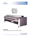
The ProGroup Instrument Corporation WellPro WP3000 Liquid Handler (Figure 1.1) is designed to
perform the following liquid handling activities on a user-programmable basis:
•
•
•
•
•
•
•
•
•
Precisely transfer liquids in volumes from 1 µL to 50 µL using disposable tips with the 24 channel
head
Precisely transfer liquids in volumes from 1 µL to 200 µL using disposable tips with the 12 channel
head
Perform serial dilutions in almost any ratio,
Perform serial dilutions of 16 wells or 24 wells simultaneously with 24 channel head
Perform serial dilutions of 8 wells or 12 wells simultaneously with 12 channel head
Precisely mix the contents of a microplate
Transfer samples to or from microplates
Perform mother-daughter “repli-plating”
Perform well to well transfer / Cherry Picking (Optional Feature and is not standard w/ instrument)
Fig 1.1 ProGroup Instrument Corporation WellPro WP3000 Liquid Handler
1
1.2
Principle of Operation
The ProGroup Instrument Corporation WellPro WP3000 Liquid Handler consists of a hand-held touch
screen controller and a liquid handling unit. A variety of reagent containers can be used to hold liquids
that will be added to the wells in a plate (or have been removed from a plate).
1.2.1 Touch Screen Controller
The ProGroup Instrument Corporation WellPro WP3000 Liquid Handler includes a touch screen display
that is used to program all operations of the unit. The controller allows the user to control parameters
such as the volumes to transfer, mix, or dispense, the transfer speed, and whether to change tips
between transfers.
1.2.2 Liquid Handling Unit
The ProGroup Instrument Corporation WellPro WP3000 Liquid Handler is an electro-mechanical transfer
unit that is comprised of two basic parts: a table and a vertical head assembly.
The table accommodates a series of interchangeable templates for the short base unit and a single
template for the long base that position the reagent containers and a magazine with the disposable tips,
etc. During operation, the table slides back and forth to bring the appropriate component under the head
assembly.
The short base unit is several inches shorter so that it can fit inside a hood. The shorter base unit does
not have the plate filling in portrait mode feature like the long base due to the table space being shorter.
The head assembly consists of three basic parts:
•
•
•
a plunger housing which contains nozzles that press into the tips to form airtight seals
a plunger block which moves up and down to aspirate and deliver samples
a tip ejector plate which removes used tips
The head assembly slides up and down to bring the tips to the appropriate height to perform the
designated operations.
The WellPro WP3000 can be configured with, a 24 channel (tip) air displacement pipetting head or a 12
channel (tip) air displacement pipetting head. Serial dilutions can be performed in the 16 or 24 channel
mode with 24 channel head to allow for maximum dilution capability with the 384 well plate or can be
performed in the 8 or 12 channel mode with 12 channel head to allow for maximum dilution capability with
the 96 well plate.
An optional single channel well to well / cherry picker head can be added to the instrument. The single
channel head can perform well to well transfers and dilutions in a 1-200 ul range for the 96 WellPro and 150 ul for the 384 WellPro. This module uses an excel spreadsheet and requires a computer to operate.
2
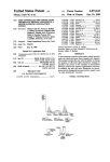
Standard WellPro (Optional single channel cherry picking head not shown)
12 Channel Liquid Head
24 Channel Liquid head
Cherry Picking Single Channel Head not shown (Refer to manual for this module)
3
1.2.3 WellPro Reagent Containers
The WellPro liquid handler can be used with the MICRO-TROUGH reagent container, each of which
consists of three reservoirs. Each reservoir holds a different amount of liquid: (e.g. 20 mL, 58 mL, and
77 mL). You can use the reservoirs to hold reagents that will be added to a plate or waste that has
been removed from a plate.
The WellPro liquid handler can be used with a 100 ml chilled reagent container. You can use this
reservoir to hold reagents that does or does not required chilled. The trough also has disposable liners
as an added benefit.
4
1.2.4 WellPro Templates
The WellPro WP3000 liquid handler uses a template to position microplates, reagent containers and tip
magazines on the movable table.
Standard templates provided:
•
Standard Template for WellPro with a Long Bed
One general purpose template is used for WellPro long bed liquid handling operations. The well
plates can be orientated with the (96 well plates) 12 well rows (A-H) or (384 well plates) 24 well rows
(A-P) landscape as shown in Figures 1.2, 1.3, 1.4, 1.5, . With the same template the plates can be
placed in a portrait orientation (96 well plates) 1-12 or (384 well plates) 1-24 well columns as shown in
Figures 1.6 and 1.7.
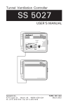
Fig 1.2 Standard Template for Long Bed WellPro showing plates positioned in landscape orientation
5
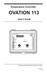
Fig 1.3 Standard Template for Long Bed WellPro showing plates positioned in landscape orientation
6
Fig 1.4 Standard Template for Long Bed WellPro showing plates positioned in landscape orientation
7
Fig 1.5 Standard Template for Long Bed WellPro showing plates positioned in landscape orientation
8
Fig 1.6 Standard Template for Long Bed WellPro showing plates positioned in portrait orientation
9
Fig 1.7 Standard Template for Long Bed WellPro showing plates positioned in portrait orientation
10
•
Standard Templates for WellPro with a Short Bed
The short bed requires two templates. One template is for positioning plates in a landscape
orientation and the other template for portrait orientation. Landscape template can accept well plates
orientated (96 well plates) 12 well rows (A-H) or (384 well plates) 24 well rows (A-P) landscape as
shown in Figure 1.8. The portrait template accepts plates in a portrait orientation (96 well plates) 1-12
or (384 well plates) 1-24 well columns as shown in Figure 1.9.
Fig 1.8 Standard Landscape Template for Short Bed WellPro showing plates positioned in landscape (note:
for portrait orientation this template must be removed and replaced with a portrait template)
11
Fig 1.9 Standard Portrait Template for Short Bed WellPro showing plates positioned in Portrait (note: for
landscape orientation this template must be removed and replaced with a landscape template)
12
About the User Manual
This User Manual has been written for the end user of the system (e.g. a laboratory technician) and
provides information about the operation and maintenance of the ProGroup Instrument Corporation
WellPro WP3000 Liquid Handler. Read the manual in its entirety prior to operating the instrument.
This User Manual has been designed to give you the information you need to:
•
•
•
•
Review safety precautions.
Install the system
Use the system in routine jobs and research.
Perform basic maintenance procedures.
This User Manual also describes features and specifications of the ProGroup Instrument Corporation
WellPro WP3000 Liquid Handler.
This manual includes the following sections:
•
•
•
•
•
•
•
•
•
•
•
Installation
System Components
Plate Filling
Serial Dilution
Plate to Plate Transfer
Position Settings
Managing Files
Linking Files
Adjusting the Tip Position for Custom Well Plates
Operating Hints and Maintenance
Specifications
13
2 INSTALLATION PROCEDURES
2.1
Overview
The ProGroup Instrument Corporation WellPro 3000 Liquid Handler is designed to be installed by the
operator. This chapter describes how the unit is to be unpacked and assembled.
2.2
Location of the Unit in the Laboratory
The unit should be installed in a facility with the following conditions:
•
•
•
•
The temperature should be maintained between 20-26oC (68-79oF). To prevent temperature
fluctuations, do not place the WellPro 3000 liquid handler in direct sunlight, near equipment that gives
off heat, or under heating or air conditioning outlets.
If flammable or toxic solvents are to be used, a suitable ventilation system should be provided.
The use of open flames in the laboratory should be prohibited.
Corrosive vapors or dust should not be present as these materials can adversely affect the long-term
performance of the system.
The Well-Pro 3000 module requires approximately 24.5” x 11.50” x 16.5” of lab bench space.
14
Note: Place the ProGroup Instrument Corporation WellPro 3000 on a stable, level bench or hood.
Excessive jarring or vibration during operation may affect its performance.
2.3
Power Requirements
The ProGroup Instrument Corporation WellPro 3000 Liquid Handler is designed to operate at 100, 120,
220 or 240 V (50/60 Hz) with a maximum power consumption of 360 watts. The operating potential is set
at the factory and is indicated on the serial number tag on the rear panel of the system.
WARNING
WARNING: Verify that this voltage is correct for your location before installation.
CAUTION
CAUTION: ProGroup Instrument Corporation WellPro 3000 Liquid Handlers shipped to
locations in the United States and Canada are supplied with a standard three-conductor
power cable and a three-terminal plug that provides an earth ground. The unit MUST be
connected to a three-terminal socket that is properly wired according to the U.S. National
Electrical Code and is grounded to a true earth ground. The use of an adapter to a twoterminal outlet is PROHIBITED.
15
2.4
Unpacking and Inspection
The ProGroup Instrument Corporation WellPro 3000 Liquid Handler is shipped in one carton that contains
the items listed in Table 2.1. When the system is received, carefully unpack the unit and verify receipt of
all components. We recommend that you save the shipping container and packing material in case you
need to move or ship the instrument.
Table 2.1 PACKING LIST
Quantity
Description
1
1
1
1
1
1
1
1
WellPro 96 Long base
WellPro 96 Long base w/ Single Channel
WellPro 96 short base
WellPro 96 short base w / Single Channel
WellPro 384 Long base
WellPro 384 Long base w / Single Channel
WellPro 384 short base
WellPro 384 short base w / Single Channel
1
1
1
2
1
1
1
1
WellPro 3000 Operators Manual
Controller Touch Screen
Plastic Cover Tinted
Templates for Short Bed Instrument
Template for Long Bed Instrument
Micro Trough 4 per pack
Chilled Reservoir
Benchtop Ionizer for the 384 Instrument only
Part Number
WP3000-96
WP3000-96-CP
WP3000-96S
WP3000-96S-CP
WP3000-384
WP3000-384-CP
WP3000-384S
WP3000-384S-CP
OM3000
8025
76090
SAMPLE
SAMPLE
4009885
If there is external damage to the shipping carton, report the damage to the shipping company and your
local ProGroup Instrument Corporation representative. If internal parts are missing or damaged, report
this to the shipping company and your local ProGroup Instrument Corporation representative as soon as
the problem is observed.
Note: If there is any apparent damage to the system, the user should investigate the nature
of the damage before plugging the unit into the mains to ensure that powering up of the
system will not create a hazardous condition or damage internal components. If the
damage appears significant, call your local ProGroup Instrument Corporation
representative before connecting the unit to the mains.
2.5
Initial Installation of the WellPro 3000 Liquid Handler
Assembly, installation and final inspection of the WellPro 3000 Liquid Handler will be done by the user. To
install the unit:
1. Connect the Touch Screen Cord to the back of the WellPro and slide the Touch Screen onto the
bracket connected to side of the unit.
2. Place the power cord to the line into the socket into the rear panel of the liquid handling unit and plug
the unit into the line.
16
Figure 2.1: The Controller Screen when Powered Up
Power up the unit. The liquid handler will initialize and the controller will present Figure 2.1. The
pipette tip head will move in the Z upward direction and the table will move in the Y outward direction
to determine the zero. If the head does not move, contact your local ProGroup Instrument Corporation
service representative for assistance.
3 SYSTEM COMPONENTS
3.1
Introduction
The ProGroup Instrument Corporation WellPro 3000 Liquid Handler system includes the following
components:
•
•
•
3.2
WellPro Controller (Section 3.2)
WellPro WP3000 Liquid Handling Unit (Section 3.3)
WellPro Reagent Troughs and Pipette Tips
WellPro WP3000 Touch Screen Controller
The WellPro WP3000 Controller includes a touch screen display which provides the operator with
complete control of all liquid handling operations. The basis of operation is via a user generated method
which includes a series of primary operations. The method can be stored and retrieved as desired.
Each primary operations provides for user control of a given aspect of the operation. Typical operations
include the volumes to transfer, mix, or dispense, the transfer speed, and whether to change tips between
transfers.
3.3
The WellPro WP3000 Liquid Handling Unit
The WellPro WP3000 Liquid Handling Unit is an electro-mechanical transfer unit that includes a table and
a vertical head assembly. The table accommodates templates which position reagent containers, a
magazine with rows of disposable tips, etc. During operation, the table slides back and forth horizontally to
bring the appropriate workstation under the head.
17
The standard head assembly consists of three basic parts:
•
•
•
A plunger housing which contains nozzles that press into the tips to form airtight seals
A plunger block which moves up and down to aspirate and deliver samples,
A tip ejector plate which removes used tips. The head assembly slides up and down vertically to bring
the tips to the appropriate height to perform the designated operations.
(A single channel nozzle for cherry picking is an additional configuration option)
A 12 or 24 channel (tip) air displacement pipetting head is included on the WellPro liquid handler as most
protocols are designed to be performed in the 12 or 24 channel mode, but serial dilutions can be
performed in the 8 or 16 channel mode to allow for maximum dilution capability with the 96 or 384 well
plate.
The table assembly drives the plate which holds the well plates and the Micro-Trough reagent containers.
The precision of this sensitive device is affected by a series of variables. These include the degree to which
the pipette tips are able to be wet, which is dependent on the viscosity of the pipetted liquid, the dimensional
accuracy of the tip orifice, piston speed and delay time. Therefore, please keep the following in mind when
using the WellPro. Liquid is pipetted with vacuum pressure generated by the pistons.
This technique requires dwell time to equalize air pressure in the pipet tips during pipetting. Pipetting time is
highly dependent upon the properties of the liquid factors. It is necessary to allow some dwell time during
pipetting operations, particularly for smaller volumes and viscous liquids. Changing the aspirate speed to a
lower setting of medium or slow will provide more dwell time.
Rinsing if dry tips are used, more time is required to saturate the dry air with moisture. Vapor pressure
increases above the pipetted liquid inside a dry tip. As a result, dry tips may cause liquid to be driven out,
compromising accuracy. To avoid this, use the mix option prior to a programmed aspiration to equalize the air
in the tips before pipetting the liquid. Proper vapor pressure will be maintained even if the device is left idle with
filled tips for a prolonged period. Tip Immersion is important to ensure that pipet tips are properly immersed in
liquid before aspirating. Tips should be immersed just below the level of the liquid and the depth should be
consistent throughout the pipetting cycle. This will prevent air from being aspirated into the tips as well as
avoid extra liquid adhering to the outside of the tip.
3.4
The WellPro Reagent Trough
The WellPro liquid handler is used with a Micro-Trough which is a reagent container. The Micro-Trough
container consists of up to three reservoirs, each of which is used to contain a reagent or solution. In
some cases, fluid from the wells is deposited in the Micro-Trough.
The WellPro also uses a 1 ml chilled trough with disposable liners for reagents that require to be kept cool
during transfer.
The WellPro WP3000 liquid handler uses templates to position microplates, reagent containers and tip
magazines on the movable table.
*Note that all WellPro’s can fill plates in landscape mode but the long bed WellPro is the only
instrument that can fill plates in both landscape and portrait orientation. The short bed can not fill in
portrait orientiation.
18
4 USER INTERFACE
4.1
Touch Screen Introduction
The basis of operation of the ProGroup Instrument Corporation WellPro 3000 Liquid Handler is the file,
which is a set of instructions and conditions that are used to perform the desired operation. The operator
can establish, store and execute files via the touch screen controller module.
The WellPro user interface consists of a touch panel that activates the liquid crystal display (LCD). From this
touch panel all program modes and variables can be easily accessed and adjusted. To pause a program,
simply press the STOP Icon on the touch panel during a run. Touching the GO Icon resumes the program.
All modes, commands and data input operations are accomplished using the touch panel. The
instructions and prompts are in dialog format. Variables can be changed by touching the text
highlighted in blue.
.
Figure 4.1
When the system is powered up, the display will be as shown in Figure 4.1. Touching the Main Menu
button will pop up the main menu screen shown below. At the main menu screen you have the option of
selecting a process and creating a file with your parameters and saving the file.
19
5 PLATE FILLING
5.1
Overview
Plate filling refers to the addition of a user specified quantity of liquid to the wells in a plate from a MicroTrough/Reservoir. The Plate Filling button is used to establish a user file which can be stored.
5.2
Creating and Editing a Plate Filling File
When you touch the Plate Filling button, the opening plate filling screen is presented. You can change the
value of each parameter to provide the desired program to fill the plates. To change a plate filling
parameter, touch the text in blue and enter the desired value.
20
Press the Def. Values button to change back to system default values
ACTUAL VOLUME IN WELL AT START is used to indicate how much liquid is in each well before any
transfer has been made. This number is used to determine how far down into the wells the tips should go
and also to prevent the instrument from attempting to add more liquid than each well can hold. This
parameter can be set from 0 to 2000 µL in 1 µL increments. Do not exceed the volume capacity of the
plate type you are using: ie. 350 µL in a standard 96 well flat plate or 1.2mL in a 1.2mL deep well plate,
etc.
21
DELIVER FROM is used to indicate the MICRO-TROUGH reservoir that contains the liquid to be
dispensed.
MIXES IN MICRO-TROUGH is used to specify mixing of the MICRO-TROUGH contents before an
aliquot is taken. Mixing of a MICRO-TROUGH is especially important with cells or other
inhomogeneous samples. This parameter can be set between 0 and 9 (0 indicates no mixing).
22
MICRO-TROUGH MIX VOLUME is used to indicate how much liquid to aspirate into the tip and
dispense back into the MICRO-TROUGH in order to mix the MICRO-TROUGH contents. This
parameter can be set from 0 to 200 µL in 1 µL increments (0 indicates no mixing) for 12 channel head
and 0 to 50 µL in 1 µL increments for 24 channel head.
DELIVERY VOLUME indicates how much solution should be dispensed into each well from the
MICRO-TROUGH reservoir. This parameter can be set from 0 to 200 µL in 1 µL increments for 12
channel head and 0 to 50 µL in 1 µL increments for 24 channel head.
23
MIXES AFTER TRANSFER is used to specify the number of mixes after the aliquot has been
delivered to the plate. This parameter may be set from 0-9 in increments of 1 (0 indicates no mix after
transfer)
PLATE ORIENTATION is used to indicate how the plate is positioned. The value that is selected
indicates the number of wells that will be under the pipette tips at one time. (Important this must be
set at A-H landscape at all times if you have a short bed WellPro) The short bed can only fill
plates in landscape but the long bed WellPro can fill in landscape and portrait orientation.
A-H for 96 well plate landscape orientation
1-12 for 96 well plate portrait orientation
A-P for 384 well plate landscape orientation
1-24 for 384 portrait orientation
MIX VOLUME is used to specify the volume of the aspirate/delivery cycles used to mix the contents of
the well after transfer.
PLATE TYPE is used to indicate the design of the bottom of the plate (V shape, U shape, Flat). This
information is used to determine the height of the liquid in each well and thus calculate how far down
24
into the wells the tips should go. If you are not using a standard microplate, select custom one of the
ten custom programs. The custom programs for non-standard plates are configured in the settings
configuration from the main menu. In the settings menu you can set the HEIGHT and determine the
amount to raise or lower the tip height. The height parameter can be set from 100 to 3500 in
increments of 1 or 25.
MICRO-TROUGH VOLUME AT START is used to indicate how much liquid is in the reservoir you
have chosen before any liquid has been removed. The system uses the delivery volume and the
number of rows to be filled to calculate the minimum volume needed to run the file and indicates it on
the display as the lower limit. You can set the value of this parameter in 1 mL increments from this
lower limit to 20 mL, 58 mL, or 77 mL for the front, middle, and rear reservoirs respectively for the
MICRO-TROUGH reservoir.
The Cool Trof can hold 100 mL
Enter the amount of liquid volume present in trof at start of the program and press OK.
Note: If tracking of volume of liquid in trof during change of programs or linking of programs then set
Track on. See screen below.
25
Pressing the Track button will turn and activate the tracking volume feature of software on. Press Rst
Volume and then Track and OK.
After pressing Rst Vol , Track and OK the program takes you back to screen 1 of 3. When you press
GO to run the program you will then be prompted to enter volume in Trof
Enter Volume in Trof:
New Volume:__________ The software will now keep track of volume used
in the trof during operation and running various programs and linking of programs.
LIQUID HANDLING SPEEDS is used to select the rate sample delivery from the tips (rapid, medium,
or slow).
LINK FILE is used to link and run a previously saved program immediately after current program. If
link file is left blank then system will run current program only. The area immediately to the right of link
file displays a number which represents a time delay between the link files if desired.
If you want the system to perform another file after the present file is complete, enter the desired file
name and time delay between programs if desired. Use the displayed keypad to enter the text of the
program to link with in the Enter Name field and select enter. Use the displayed keypad to enter the
seconds in the delay time field. When complete click on Exit
Now the Link File field should display the file you linked to and the specified time delay.
Pause
Enter Delay Time: Instead of a time delay you also have the option to have a pop up screen prompt
you to press continue before starting the next program. This is done by entering the number “9999”
which will create the pause before proceeding command.
26
The above display is for the WellPro 12 channel (96 well plate) in landscape or portrait
The above display is for WellPro 24 channel head (384 well plate)
27
FILL PLATE ROWS is used to indicate the rows of the plate to fill and which to leave unfilled. Rows
are designated by letters A through P for 384 well plates and A through H for 96 well plates. To select
row A, press the A button which will then fill in with red. If you want all rows to be filled, press each
button. For rows that you don’t want filled then do not press the button with corresponding row letter.
Non filled rows will have no red filled in on the box.
ENTER FIRST TIP ROW is used to specify which row of tips to use. Rows of the tip magazine are
designated by letters A through P (back to front) or A through H. The program will start with first tip
row specified and if the change tips is YES it will go to change tip row. For example:
The screen above will start with row P of tips and fill row A of well plate. It will then eject tips and pick
up row O of tips and then fill row B of well plate etc.
If change tips is set to NO then program will use row P of tip rack to fill all the rows selected for well
plate.
CHANGE TIPS is used to indicate if the tips should be removed after the first liquid is dispensed and
a new set of tips from the tip magazine should be placed on the pipette head, thus decreasing
carryover. If you don't want to change tips, then the same tips will be used throughout the entire
operation.
Note: The above does not track tip rows used. If tip row tracking is needed for tasks such as linking
programs or if you need to keep track of last row used after running a program so you know where to
start with next available tip row then use the following setup below.
28
First Tip Row NAT - Setting the next First Tip Row to NAT will keep track of next available tip that
has not been used. This should be set at NAT if you are linking programs or wanting to keep track of
next row of tips to be used while manual running programs. If you want to reset the next available tip
row to the beginning then at screen one press Rst NAT. See below.
When you press Rst NAT located on screen one a Pop Up screen will be displayed asking to make
sure the deck is OK. If you press OK another screen will Pop Up asking;
Change the magazine and select the next tip row, Next tip row:
Note: Changing magazine is not required if you would like to continue to use same tips.
CHANGE TIPS is used to indicate if the tips should be removed after the first liquid is dispensed and
a new set of tips from the tip magazine should be placed on the pipette head, thus decreasing
carryover. If you don't want to change tips, then the same tips will be used throughout the entire
operation.
29
Touching/Pressing the GO button will pop up a message to confirm that the appropriate plates are in
position on the deck. Once you have confirmed then touch/press the OK button.
The above display is for the WellPro 12 channel head (96 well plate)
30
The above display is for the WellPro 24 channel head (384 well plate)
The plate filling will begin with a status screen showing the rows as they are being filled. Pressing the
STOP button while program is running will cause a pause in the program and pop up a program paused
message with option to abort or continue or abort and return tips.
Pressing the STOP button while program is running will cause a pause in the program and pop up a
program paused message with option to abort, continue or abort and return tips.
Pressing the Abort button will abort the program or pressing the continue button will continue with the
program. The abort and return tips option will return the tips to the rack and abort the program.
31
Saving a Program After setting the variables to desired value go back to screen 1 of the plate filling
menu and press the Save button to save the parameters as a program file. Use the display keypad to
enter the desired program name. The name can be any alpha numeric name. After entering the name
click on enter button and then the save button. You are now ready to click on the exit button and go
back to main plate filling screen.
The save can be performed after setting the variables and before pressing GO to run the program. Or
the program can be saved after running the program by pressing the back button to screen 1 of the
plate filling menu and then press save button.
To load a saved program use the up or down arrow keys to scroll and select the program to load and
run. This will load the parameters for the program to be run. Then go to the next screen and press
“GO” button to run program.
32
To delete a program you can choose delete to delete specific files you have saved in the serial
dilution, plate to plate and filling sections. Choose delete file to delete a specific file/program.
A message will pop up “Do you want to delete this file?” you can choose yes or no to continue.
Rst NAT – Reset next available tip row. Pressing this will reset the next available tip row to the first
row in the tip rack. Rst NAT is only active when NAT is selected on last screen in the First Tip Row
field.
Rst VOL – Will reset the volume in the trough. This allows tracking the level of liquid in the trough as it
is used. This is only active if Tracking is set to ON.
A “GO” button exists at the lower right hand corner of every screen. This can be pressed at anytime to
run the current program loaded into the system.
33
6 SERIAL DILUTION
6.1
Overview
Serial Dilution is the progressive dilution and redilution of a liquid. In this process, a sample is added to a
diluent and the two are mixed. An aliquot is then removed for addition to the next diluent-containing well.
This sequence is repeated until the desired number of dilutions have been obtained ("serial dilutions"). As
an example, if equal volumes of sample and diluent were mixed during each step of the series, the
sample concentration would be 1:2, 1:4, 1:8, 1:16, 1:32, and so on in sequential rows.
6.2
Creating and Editing a Serial Dilution File
At the main menu screen you have the option of selecting a process and creating a file with your
parameters and saving the file. Pressing the Serial Dilution button will open up a screen for changing the
serial dilution parameters.
Press the Def. Values button to change back to system default values
34
Pressing the text values/parameters in blue will lead to other screens shown below so that parameters
can be changed.
Rst NAT – Reset next available tip row. Pressing this will reset the next available tip row to the first
row in the tip rack. Rst NAT is only active when NAT is selected on last screen in the First Tip Row
field.
A “GO” button exists at the lower right hand corner of every screen. This can be pressed at anytime to
run the current program loaded into the system.
VOLUME IN SOURCE WELL AT START is used to tell the system how much volume is in the initial
source row.
35
ACTUAL VOLUME IN WELL is used to tell the system how much diluent is in each well before any
transfer has been made. This parameter does not pertain to the first row, which contains the sample.
The system uses this number to determine how far down into the wells the tips should go, and also to
prevent the instrument from attempting to withdraw more sample than is actually present. This
parameter can be set from 0 to 2000 µL in 1 µL increments. Verify the capacity of the plate type you
are using is greater than the volume selected.
The above display is for WellPro 12 channel (96 well plate)
36
The above display is for WellPro 24 channel (384 well plate)
TRANSFER VOLUME indicates how much sample should be withdrawn from the original well for
transfer to the new well during a serial dilution. This parameter can be set from 0 to 50 µL in 1 µL
increments for 384 well plates and 0 to 200 µL in 1 µL increments for 96 well plates. A transfer
volume of 0 may be used if you wish to simply mix the contents of the well.
MIXES BEFORE TRANSFER is used to indicate the number of aspiration/delivery cycles that should
be performed before transferring a sample. As an example, if you are diluting cells which may settle,
the MIX BEFORE TRANSFER step might be used to agitate them back into suspension before
transfer by mixing. This parameter can be set from 0 to 9 (0 indicates no mixing).
37
MIXES AFTER TRANSFER is used to indicate the number of aspiration/delivery cycles that should be
performed after transferring a sample. This parameter can be set from 0 to 9 (0 indicates no mixing).
MIX VOLUME is used to tell the system how much solution should be used in the Mix step. Typically this
volume is 50% of the total volume in the well to be mixed, but will be more or less depending on the
application (when mixing cells, it may be desirable to use a lower volume of the total volume).
38
PLATE TYPE is used to indicate the design of the bottom of the plate (V shape, U shape, Flat). This
information is used to determine the height of the liquid in each well and thus calculate how far down
into the wells the tips should go. If you are not using a standard microplate, select custom for one of
the ten custom plate types available. The custom programs for non-standard plates are configured in
the settings configuration from the main menu. In the settings menu you can set these parameters
and determine the amount to raise or lower the tip height. The height parameter can be set from 100
to 3500 in increments of 1 or 25.
39
Empty Last Row to: This parameter determines where to place the extra volume transferred into the
last row.
PLATE ORIENTATION is used to indicate how the plate is positioned. The value that is selected
indicates the number of wells that will be under the pipette tips at one time.
A-H for 96 well plate landscape orientation
1-12 for 96 well plate portrait orientation
A-P for 384 well plate landscape orientation
1-24 for 384 portrait orientation
40
EMPTY LAST ROW TO is used to tell the system where to place the extra volume of liquid
transferred into the last row of wells after a serial dilution.
1. If you select OFF, the extra liquid will be left in the last row of wells.
2. If you select 1ST ROW, the extra liquid will be removed from the last row of wells and return it to
the first row of wells you chose in ROWS TO DILUTE.
3. If you select MAGAZINE, the system will remove the extra liquid and discard it into the tip
magazine.
4. If you select MICRO-TROUGH, the system will remove the extra liquid and discard it into the rear
reservoir of a MICRO-TROUGH container located in the P2 cavity of the template.
Note: MICRO-TROUGH will appear on the display only when the 12 or 24 wells (landscape)
across PLATE ORIENTATION selected. If performing a serial dilution in portrait then this
option is not available.
LIQUID HANDLING SPEEDS is used to select the rate sample delivery from the tips (rapid, medium,
or slow).
LINK TO FILE is used to indicate what the system should do after it completes the file it is currently
running.
If you want the system to stop at the end of the file do not enter anything in the link file field.
If you want the system to perform another file after the present file is complete, link to the desired file.
CHANGE TIPS is used to indicate if the tips should be removed after the first liquid is dispensed and
a new set of tips from the tip magazine should be placed on the pipette head, thus decreasing
carryover. If you don't want to change tips, then the same tips will be used throughout the entire
operation.
41
Above screen represents WellPro 12 channel (96 well plate)
Above screen represents WellPro 24 channel (384 well plate)
FILL PLATE ROWS TO DILUTE is used to indicate the rows of the plate are to be included in the
serial dilution. Rows are designated by letters A through P (back to front) for 384 well plates in the "24
across" configuration and 1 through 16 in the "16 across" configuration. Rows are designated by
letters A through H for 96 well plates in “12 across” configuration and 1 through 8 in the “8 across”
configuration. To select row A, press the A button which will then fill in with red. If you want all rows to
be filled, press each button. For rows that you don’t want filled then do not press the button with
corresponding row letter. Non filled rows will have no red filled in on the box.
ENTER FIRST TIP ROW is used to specify which row of tips to use. Rows of the tip magazine are
designated by letters A through P (back to front) or A through H.
42
First Tip Row NAT - Setting the next First Tip Row to NAT will keep track of next available tip that
has not been used. This should be set at NAT if you are linking programs or wanting to keep track of
next row of tips to be used while manual running programs. If you want to reset the next available tip
row to the beginning then at screen one press Rst NAT. See below.
When you press Rst NAT located on screen one a Pop Up screen will be displayed asking to make
sure the deck is OK. If you press OK another screen will pop up asking;
Change the magazine and select the next tip row, Next tip row:
Note: Changing magazine is not required if you would like to continue to use same tips.
43
Touching/Pressing the GO button will pop up a message to confirm that the appropriate plates are in
position on the deck. Once you have confirmed then touch/press the OK button.
Above screen is for WellPro 12 channel (96 well plate)
44
Above screen is for WellPro 24 channel (384 well plate)
The serial dilution will begin with a status screen showing the rows as they are being filled. Pressing
the STOP button while program is running will cause a pause in the program and pop up a program
paused message with option to abort or continue.
Pressing the STOP button while program is running will cause a pause in the program and pop up a
program paused message with option to abort, continue or abort and return tips.
Pressing the Abort button will abort the program or pressing the continue button will continue with the
program. The abort and return tips option will return the tips to the rack and abort the program.
45
Saving a Program after setting the variables to desired value go back to screen 1 of the serial dilution
menu and press the Save button to save the parameters as a program file.
Use the keyboard on the display to enter the alpha numeric name of the program and then press enter
and save.
The save can be performed after setting the variables and before pressing GO to run the program. Or
the program can be saved after running the program by pressing the back button to screen 1 of the
serial dilution menu and then press save button.
To load a saved program press the load button and then select a file to load by using the up or down
arrow scroll buttons. Press the load button then go to next screen and press GO button to run program.
46
7 PLATE TO PLATE TRANSFER
7.1
Overview
Transferring an aliquot of sample from one plate to another is called "plate-to-plate" transfer or "replica
plating." This technique allows for transfer of samples in a SOURCE plate to a RECEIVER plate for
assay, culture, etc.
The steps required to perform the plate transfer are:
1. Aspirate sample from source plate.
2. Deliver sample to receiver plate.
3. Replace used tips with fresh ones and proceed to the next sample row, etc.
7.2
Types of Plate to Plate Transfer
There are two general types of Plate to Plate Transfer:
1. transfer any single row in one plate to any other single row in another plate.
2. transfer any single row in one plate to two or more rows in another plate.
The program allows you to specify the direction of the transfer. The default direction is from plate 2 to
plate 1, but the system also allows you to transfer from plate 1 to plate 2, so that either plate can be used
as the DESTINATION plate. As examples, you can transfer from row A of plate 1 to row B of plate 2 or
you can transfer from row A of plate 2 to rows A, B, and C of plate 1. This enables you to set up an assay
plate to do duplicates, triplicates, etc.
At the main menu screen you have the option of selecting a process and creating a file with your
parameters and saving the file. Select the Plate to Plate button for changing plate transfer parameters.
47
7.3
Creating and Editing a Plate to Plate Transfer File
Transferring an aliquot of sample from one plate to another is called "plate-to-plate" transfer or "replica
plating." This technique allows for transfer of samples in a SOURCE plate to a RECEIVER plate for
assay, culture, etc. The Plate To Plate button is used to establish a user file which can be stored and used
as desired.
Press the Def. Values button to change back to system default values
Above display for WellPro 12 channel (96 well plate)
48
Above display for WellPro 24 channel (384 well plate)
The TRANSFER MODE/DIRECTION is a feature that is especially useful when it is combined with FILE
LINK because it allows you to transfer duplicate samples from the rows of one plate to another plate.
Thus, using these functions in combination makes it possible to transfer from row A of plate 1 to rows A
and B of plate 2, then automatically continue with another file which transfers from row B of plate 1 to
rows C and D of plate 2, and so on.
TRANSFER MODE/DIRECTION also allows you to use a 384 well plate (24 channel head) or 96 well
plate (12 channel head) as a reagent reservoir to deliver multiple reagents to a single assay plate. You
can place the same or different reagents in each of the 24 or 12 columns, and/or each of the 16 or 8 rows
of the source plate. These reagents can be delivered to specified rows on the destination plate. This
arrangement minimizes reagent waste.
TRANSFER DIRECTION is used to indicate whether the system should transfer from plate 2 to plate 1 or
from plate 1 to plate 2 (i.e. either plate 1 (the plate in the front cavity of the template) or plate 2 (the plate
in the middle cavity) can be used as the source plate.
VOLUME IN WELL PLATE 1 is used to indicate how much liquid is in each well of plate 1. The
system uses this value to determine how far down into the wells the tips should go and also to prevent
exceeding the volume capacity of the wells.
49
VOLUME IN WELL PLATE 2 is used to indicate how much liquid is in each well of plate 2. The
system uses this value to determine how far down into the wells the tips should go and also to prevent
exceeding the volume capacity of the wells.
TRANSFER MODE is used to tell the system whether to transfer 1 to 1 one row of plate 1 to the
corresponding row of plate 2, or to transfer one row of plate 1 to several different or multiple rows of
plate 2.
50
TRANSFER VOLUME is used to tell the system how much sample to withdraw from a source well for
transfer to a new well during a plate transfer. This parameter can be set in 1 µL increments. The
system calculates the maximum TRANSFER VOLUME for the row by dividing the VOLUME IN WELL
AT START by the number of transfers specified for that row.
MIXES BEFORE TRANSFER is used to indicate the number of aspiration/delivery cycles that should be
performed before transferring a sample. For example, when you are diluting cells which may settle, you
should agitate them back into suspension before transfer by mixing. This parameter can be set from 0 to
9.
MIXES AFTER TRANSFER is used to indicate the number of aspiration/delivery cycles that should be
performed after transferring a sample. For example, when you are diluting cells which may settle, you
should agitate them back into suspension after transfer by mixing. This parameter can be set from 0 to 9.
MIX VOLUME is used to tell the system how much solution should be used in the Mix step.
CHANGE TIPS is used to indicate if the tips should be removed after the first liquid is dispensed and a
new set of tips from the tip magazine should be placed on the pipette head, thus decreasing carryover. If
you don't want to change tips, then the same tips will be used throughout the entire operation.
51
Above display for WellPro 12 channel (96 well plate)
Above display for WellPro 24 channel (384 well plate)
ENTER FIRST TIP ROW is used to specify which row of tips to use. Rows of the tip magazine are
designated by letters A through P (back to front 24 channel head) or A through H (back to front for 12
channel head).
SOURCE ROW is used to indicate which row of the SOURCE plate is used to withdraw samples
from. This parameter only appears if the "1 to SEVERAL" mode is selected in this file. In that
instance, the SOURCE row specified acts as the single source row for transfer to several receiving or
DESTINATION rows.
First Tip Row NAT - Setting the next First Tip Row to NAT will keep track of next available tip that
has not been used. This should be set at NAT if you are linking programs or wanting to keep track of
next row of tips to be used while manual running programs. If you want to reset the next available tip
row to the beginning then at screen one press Rst NAT. See below.
52
When you press Rst NAT located on screen one a Pop Up screen will be displayed asking to make
sure the deck is OK. If you press OK another screen will pop up asking;
Change the magazine and select the next tip row, Next tip row:
Note: Changing magazine is not required if you would like to continue to use same tips.
PLATE 1 TYPE is used to indicate the design of the bottom of plate 1. This information is used to
determine the height of the liquid in each well and thus calculate how far down into the wells the tips
should go. If you are not using a standard microplate, select CUSTOM and determine the amount to
raise or lower the tip height.
53
PLATE 2 TYPE is used to indicate the design of the bottom of plate 2. This information is used to
determine the height of the liquid in each well and thus calculate how far down into the wells the tips
should go. If you are not using a standard microplate, select CUSTOM and determine the amount to
raise or lower the tip height.
LINK TO FILE is used to indicate what the system should do after it completes the file it is currently
running.
If you want the system to stop at the end of the file do not enter anything in the link file field.
If you want the system to perform another file after the present file is complete, enter the name of the
file in the enter name field and enter amount of seconds would like for time delay before running the
next file. Press enter after entering text in the fields to accept and then exit.
Pause
Enter Delay Time: Instead of a time delay you also have the option to have a pop up screen prompt
you to press continue before starting the next program. This is done by entering the number “9999”
which will create the pause before proceeding command.
54
1 to 1transfer, Above display for WellPro 12 channel (96 well plate)
1 to 1transfer, Above display for WellPro 24 channel (384 well plate)
TRANSFER ROW is used to indicate which row of the source TRANSFER plate is used to place
liquid in during transfer to the corresponding row on destination plate.
55
1 to Several, Above display for WellPro 24 channel (384 plate)
SOURCE ROW, the SOURCE row specified acts as the single source row for transfer to several
receiving or DESTINATION rows.
DESTINATION ROW is used to indicate which row of the DESTINATION plate is used to place liquid
in during transfer. This parameter only appears if the "1 to SEVERAL" mode is selected in this file. In
that instance, the SOURCE row specified acts as the single source row for transfer to several
receiving or DESTINATION rows.
Touching/Pressing the GO button will pop up a message to confirm that the appropriate plates are in
position on the deck. Once you have confirmed then touch/press the OK button.
56
Above display for WellPro 12 channel (96 well plate)
Above display for WellPro 24 channel (384 well plate)
The plate filling will begin with a status screen showing the rows as they are being filled. Pressing the
STOP button while program is running will cause a pause in the program and pop up a program paused
message with option to abort or continue
57
Pressing the STOP button while program is running will cause a pause in the program and pop up a
program paused message with option to abort or continue.
Pressing the Abort button will abort the program and pressing the continue button will continue with
the program.
After setting the variables to desired value go back to screen 1 of the plate to plate transfer menu and
press the Save button to save the parameters. Enter the desired file name in the Enter Name field and
click on enter button then the save button.
The save can be performed after setting the variables and before pressing GO to run the program. Or
the program can be saved after running the program by pressing the back button to screen 1 of the
plate to plate transfer menu and then press save button.
58
To load a saved program press the load button and then use the up or down scroll button to select the
program to run.
Rst NAT and NAT is used to reset the next available tip row to be used in the tip rack. This will set
the tip tracking feature and will keep track of last tip row used.
59
8 HOST CONTROL / CHERRY PICKING
8.1
Overview
Host Control is the process for sending commands from a computer into the serial port of the WellPro.
This is also used for sending information from a computer such as excel spreadsheet data to the WellPro
for our cherry picker single channel nozzle. Refer to cherry picking manual for more information on the
operation of the single channel module.
Pressing the Host Control button will open up the Host Control screen.
Host Control / Cherry Picking Screen allows for connection to a computer or other device via the serial
port. Head position, Deck position and Tip Volume can be programmed from software such as hyper
terminal, .net and others. This function is used when the WellPro needs to be integrated into a larger
platform which controls the software commands.
60
Implemented Serial Commands
Commands
HOME(Arg)
Example
WellPro Response
HOME(ALL)\r
HOME(ALL)OK\r
Arg: X, Y, Z, ALL
MOVE(Arg,Pos,Spd)
Arg: X, Y, Z
Pos: 0 to axis limit
Spd: 1 - 4
FILL_TIPS()
MOVE(X,125,2)\r
MOVE(X,125,2)OK\r
FILL_TIPS()\r
FILL_TIPS()OK\r
HOME_TIPS()
HOME_TIPS ()\r
HOME_TIPS ()OK\r
WITHDRAW(value)
WITHDRAW(50)\r
WITHDRAW(50)OK\r
DISPENSE(41)\r
DISPENSE(41)OK\r
REMAINING()
REMAINING()\r
25\r
PICK_TIPS(col, mag)
Column: 1- 8
Magazine: LAND - PORT
PICK_TIPS(3,PORT)\r
PICK_TIPS(3,PORT)OK\r
EJECT_TIPS(column)
Column: 1- 8
Column: 0 (eject only,
no
motion)
Magazine: LAND - PORT
EJECT_TIPS(2)\r
EJECT_TIPS(2))OK\r
DELAY_SEC(value)
DELAY_SEC(5)\r
DELAYSEC(5)OK\r
Value: 1 - 200
DISPENSE(value)
Value: 1 - 200
Delay for the number of
seconds specified.
61
Comments
Initialize the WellPro machine.
It’s also highly recommended
that you use it inside your
programs to update the
remaining volume in the
controller and avoid float
calculation’s offset.
It makes an absolute
movement in the specified
axis.
Fills the tips to maximum
volume from any previous
position.
Dispense all the remaining
volume in the tips from any
previous position.
This command indicates to the
WellPro the amount of liquid to
withdraw in uL. Value must be
an integer number in the
range of 1 to 200.
This command indicates to the
WellPro the amount of liquid to
dispense in uL. Value must be
an integer number in the
range of 1 to 200.
Returns the remaining volume
in uL.
The WellPro will pick up the
tips from the specified column.
You must specifie the
orientation of the tip magazine
(LAND or PORT).
The WellPro will eject the tips
to the specified column. When
column=0, the machine will
eject the tips in it’s actual
position.
You must specifie the
orientation of the tip magazine
(LAND or PORT).
Causes the program to pause
for the number of seconds
specified. Seconds must be a
whole number in the range of 1
to 1x10⁸.
DELAY_MS(value)
DELAY_SEC(5)\r
DELAYSEC(5)OK\r
RATE(2)\r
RATE(2)OK\r
RATE?()
RATE?()\r
2\r
BEEP(value)
BEEP(350)\r
BEEP(350)OK\r
Causes the controller to
‘beep’ for the number
of milliseconds
specified.
WARNING()
WARNING()\r
WARNING()OK\r
Delay for the number of
milliseconds specified.
RATE(speed)
Speed: 1-4
Causes the program to pause
for the number of milliseconds
specified. Milliseconds must be
a whole number in the range of
1 to 1x10⁸.
Changes the withdraw and
dispense speed. 1 is the lowest
speed and 4 is the highest
speed.
Returns the current rate speed.
Returns an integer number
between 1 and 4.
Causes the controller to emit a
‘beep’ sound for the number of
milliseconds specified.
Causes the controller to emit a
3-beep tone. Useful as an
attention getting warning
signal.
9 SETTINGS CONTROL
9.1
Overview
Settings section allows the user to set the internal clock and alter the settings for serial port configuration.
It also allows position adjustment for non standard microplates in a custom file and manual moving head
and deck positions.
Pressing the Settings button will open the Settings screen.
62
Pressing the Set Clock button will open a screen where the settings can be changed. Pressing the Set
Serial Port will open the screen for changing the Serial Port configuration. These settings will be set at
the factory.
Pressing the text in blue will allow you to change the variable date settings. Press OK button after
changing the variable to accept the change.
63
The serial port configuration allows for setting values required to communicate to external computers
or other devices. The values are preset at the factory.
The Manage user files ………………….
DownLoad Position Settings and Files from Computer to the WellPro
•
•
•
Connect serial cable to back of WellPro and to Computer
Confirm on Touch screen that settings are
Baud Rate: 9600
Parity: None
Data Bits: 8
Stop Bits: 1
Before performing the procedure the first time you need to setup the Hypterminal parameters
located on your computer. Go to start menu/All programs/Accessories /Communications then
choose Hyperterminal. A popup up menu will now appear for you to enter a name for this. You
can enter a name such as WellPro and continue or give it no name to continue. Now you should
see the following popup menu
64
•
•
Hyperterminal –
65
66
•
•
•
Go to Touch Screen and into Manage Files
Click on “Restore settings from PC”
Go back to Hyperterminal menu on computer and “Transfer” then Click on “Send Text File” and
pick the file to send from “WellPro Backup” folder on desktop.
67
•
•
IMPORTANT WAIT FOR THE END COMMAND TO SHOW IN HYPERTERMINAL MENU AND LISTEN FOR
A “BEEP” sound before disconnecting. Now you can press “call” disconnect and close the
Hyperterminal menu.
For downloading the program files to Wellpro repeat the same process used for downloading
the settings except for now click on “Restore all files from PC” in the manage user file section
of touchscreen instead of “Restore all files from PC”.
68
Upload Customer Settings and Files from WellPro to a Computer
•
•
Connect serial cable to back of WellPro and to Computer
Confirm on Touch screen that settings are
Baud Rate: 9600
Parity: None
Data Bits: 8
Stop Bits: 1
•
•
Click on the Hypterminal Icon located on Desktop
Go back to Hyperterminal menu on computer and “Transfer” then Click on “Capture Text” and
pick the location and file name you would like to save it as.
69
•
•
•
•
Press “Start”
Go to Touch Screen and into Manage Files
Click on “Download Settings to PC”
IMPORTANT WAIT FOR THE END COMMAND TO SHOW IN HYPERTERMINAL MENU AND LISTEN FOR
A “BEEP” sound (could take a couple of minutes ) before you continue. Now press “capture
text” and then “Stop” (very important) now you can disconnect and close the Hyperterminal
menu.
•
For downloading the customer backup program files to Wellpro repeat the same process used
for downloading the settings except for now click on “Download all files to PC” in the manage
user file section of touchscreen.
10 ADJUSTING THE TIP HEIGHT – POSITION ADJUST SECTION
10.1
Overview
The depth of the tips in the wells must be properly set in order for the system to accurately aspirate fluid.
When standard microplates are used, this depth is set by choosing one of the preset values --"FLAT", "U",
or "V" that is presented in the PLATE TYPE parameter in the various files. However, when other plates
are used (in a few special situations), it will be necessary to manually set the tip height using custom file in
the settings menu under the position adjust section.
70
This position adjust screen allows for setting of positions for non standard plates. This menu also
allows for manual positioning of the head and deck positions.
10.1.1 Editing/Running the Position Adjustment Menu
You can change the value of each parameter as desired to provide the desired program to fill the plates.
Positions can be moved at one or at twenty five microsteps at a time.
Caution; Only change settings for Custom under actual rack. Do not change settings for any
other type of plate under the actual rack options. All other actual rack options besides custom
are set at the factory and changing could result in damage to the instrument and misalignment during
operation.
For setting positions of your non standard plate;
1.
2.
3.
4.
Press Home All button will home the machine.
Place non standard plate onto deck of Wellpro.
Manual press a pipette tip onto nozzle one of liquid head.
Choose the custom plate number you want associated with this plate. Have option to choose
from 1 to 10 custom files.
5. Select land (landscape) or Port (portrait) for the well plate in the Orient button.
71
6. Using the arrow keys press left or right until deck moves the plate so the pipette tip on head is
aligned to center of the plate well. When aligned then press the deck pos button in the “save
current position as:” and enter the deck position value.
7. Using the arrow keys press up or down arrow to move the tip to the top surface of the well
plate. Then press the “tip top button” in the “save current position as:” and enter the value
shown for the head position.
72
8. Using the arrow down key move the pipette tip head position until the tip touches the bottom
of the well. Use caution when moving the head down with arrow key, when nearing the bottom
of well use the microstep 1 arrow. When the tip touches bottom of well enter the value shown
in head position into the tip bottom value shown under “save current position”.
To determine if tip is at bottom of well try slightly moving plate by hand while moving head
down. Once you feel resistance then that means tip has reached bottom of well. At the correct
tip bottom position the plate can be moved side to side but not up or down.
73
9. Using the arrow up key move the head pipette tip above the top surface of plate. The bottom
of the tip should be moved to a position above the plate that it has no chance of hitting any
objects on the deck if the deck was to be moved. This is the position that the tip will be at
while the deck is moving the plate so that it will clear the plate. This is considered the tip safe
position. Enter the Head position value into the “save current position as:” tip safe value.
10. Enter the volume of liquid in the wells of the well plate.
To enter values in the “save current position as:” click on the blue text next to position that requires
changing. After clicking on text a pop up screen with numbers will be shown. Click on the numbers of
desired value and click on enter when finished.
74
Calibrating Liquids
For liquids that require an accuracy adjustment during volume dispensing, you can determine the
calibration factor that adjusts to the specific gravity of the liquid. The Volumetric Calculation Settings
adjusts the movement of the piston motor to improve pipetting accuracy of specified liquids.
WellPro is factory calibrated for distilled water at room temperature; however, you can add calibration
values to improve pipetting accuracy of liquids with specific gravity that is significantly different from water.
This is the calibration screen for adjusting settings of pipetting accuracy. These settings should only be
changed by an authorized technician or designated quality control technician.
Backlash – This setting will compensate for backlash effects resulting from mechanical components. To
set the backlash setting you must first place a pipette tip on a nozzle. Next fill a trough with distilled
water and aspirated 5ul. To aspirate 5ul perform the following;
1. Click on the Plunger:
Enter in a 1200 value and press enter (The liquid head will move down)
2. Click on the plunger:
Enter in a 1100 value and press enter (The liquid head will move up)
3. Pick and place the trough so that the end of the pipette tip is submerged into the distilled
water.
4. While the tip is submerged enter a value of 1000 in the Plunger setting and press enter. This
will aspirate 5ul of water.
5. Next remove the trough and press the -25 (negative arrow key) ONCE. Now take a fine tip felt
pin and carefully mark a line where the bottom of water line is located on the tip while still on
the nozzle.
6. Now press -25 arrow once and then plus 25 arrow once. Perform this sequence 16 times. After
performing this operation the water line should be at the original position and at the felt tip
marked line. If it is below the line then the backlash setting needs to be reduced and if water
level is above the felt tip marked line then the backlash number needs to be increased.
Continue this process until a backlash setting is found so that the water movement distance
level is repeatable.
75
Tip Volume – Volume pipette tip being used. This will usually be 200ul for 96 well plate (12 channel
head) WellPro or 50ul for 284 well plate (24 channel head) WellPro.
EJECT – This setting determines how far the tip ejection bar moves to eject tips. This setting should
never need adjusting. If tips are not ejecting from nozzle then please contact a ProGroup technician
for technical assistance. Adjusting this setting can result in damage to the liquid head.
Offset – Is for adjusting volume for viscous liquids. Contact ProGroup technician for technical
assistance.
Max Vol – This will set the upper liquid calibration limit. The max volume should initial be set at 1000
for a 50ul tip (24 channel head) and 4000 for a 200ul tip (12 channel head) and then press home all.
Now use the plate filling routine to fill with volume of 50ul (24 channel) or volume of 200ul (12
channel) then use a gravametric method or reader to determine accuracy. Determine the percentage
difference from the actual result to the theoretical value. Now reduce or increase the 1000 for 50ul tip
or the 4000 for a 200ul tip setting by the same percentage difference. Run the plate routine again with
200ul or 50ul and record the results. The results should now be in acceptable range.
1 ul Steps- This will set the lower liquid calibration limit. To calibrate this setting the value should be
changed to 8 steps for 12 channel head and 20 steps for 24 channel head. Now use the plate filling
routine to fill with volume of 1ul and then use a gravimetric method or reader to determine accuracy.
Determine the difference from actual result to the theoretical value. If the liquid is low then increase
the motor step by 1 if the liquid result is high then decrease the value by 1 step. Run the plate routine
again and record the results. Repeat process until acceptable results are produced.
Air Gap – This feature moves the liquid head one extra position after each dispense. This feature helps
dispense all liquid that remains in the tip after each dispense. Factory settings should be acceptable
for most applications but may need to be changed depending on viscosity of fluid.
A value of 20 steps for 24 channel head will result in approximately 1ul air gap. A value of 8 steps for
12 channel head will result in approximately 1ul air gap.
The air volume should be sufficient to assist the separation of the droplet from the tip to the well bottom,
but not so great that air bubbles become a problem. The air gap is parameter that is often optimized by
trial and error.
Buzzer – Clicking on the Disable/Enable button will toggle the buzzer to disable or enable. This will
enable or disable sound when you touch icons/buttons on the touch screen.
Backlight – This feature will put the touch screen in a sleep mode after not using for a specified
amount of minutes. Sleep mode will extend the life of the touch screen.
Password – The password comes with a factory setting of 1234. The password can be changed to your
personal preference. After choosing a password you should document the password and store in a safe
place. The password is required to access the settings area of the software.
+/- Feature increases or decreases the contrast of the touch screen display.
Battery – Tracks the battery life of the touch screen display
Optimizing Pipetting Performance for Small Volumes
Precision and accuracy can be difficult to obtain when pipetting small liquid volumes, such as 1.0 µL.
76
Critical parameters affecting performance included: Pipetting speed (slower is better for small volumes),
Plate height (tip should be 0.1-0.3 mm above the well bottom). Slower pipetting speed prevented droplets
that formed at the ends of the tips from contacting the sides or top of the wells as the plate was raised.
Optimal plate height ensured that the droplets made contact with the well bottom and were removed from
the tip during the dispense step.
Piston Speed: Slow piston speed is recommended for small volume aspiration and dispensing.
Plate Height: Plate height requires some trial and error to determine the optimal distance from the well
bottom. A height that places the tips too deep in the wells will seal the tip to the well bottom and not allow
the liquid to leave the tip. If the tips are not deep enough, the dispensed droplet will not make contact with
the well bottom and will not remove the droplet from the tip (see the following diagrams).
Position of the tip in the plate before dispense
Position of the pipet tip during dispense of
Liquid and air blowout/ air gap
When positioning the plate under the tips for a small volume dispense, allow approximately 0.1-0.3mm of
space above the well bottom prior to executing the dispense step to allow the droplet to contact the
bottom of the well.
Air Gap:
The air volume should be sufficient to assist the separation of the droplet from the tip to the well bottom,
but not so great that air bubbles become a problem. The air gap is parameter that is often optimized by
trial and error. Approximately every 20 steps = 1ul of air gap for 24 channel head and 8 steps = 1ul of air
gap for 12 channel head.
77
WellPro Support screen can be accessed from the support button located in lower right corner of the main
menu. This screen lists available pipette tips and troughs with corresponding part numbers. Please use
these part numbers when ordering supplies.
11 LINKING FILES
11.1
Overview
The FILE LINK feature is provided to allow you to join two (or more) stored files as a sequence enabling
the user to automate very complex liquid-handling operations. This prompt permits you to direct the
WellPro liquid handler to transfer control to another file immediately after completing the file that it is
currently running instead of terminating the operation of the file.
78
11.2
Using Linked Files
When the system is operating using a linked file sequence, the sequence will use the tips indicated in the
ENTER FIRST TIP ROW prompt for the first file in the sequence. This prompt appears regardless of
whether the tips are to be changed in the first file. The user should respond by specifying the row of tips
that you want the WellPro liquid handler to select first.
The WellPro uses the same "counter" to keep track of which tips have been used, whether you have
specified tip changes or not. Accordingly, each time the WellPro liquid handler links to the next file in a
chain, it sequences through the tip magazine to select the next row of fresh, uncontaminated tips.
Likewise, if you start a new file, or restart the same file, the counter automatically increments, causing the
WellPro liquid handler to select the next row of unused tips.
When the last row of tips (row A) has been used, the WellPro liquid handler stops automatically and
displays the ENTER FIRST TIP ROW prompt again. Change the magazine and specify the row of tips
that you want to start with.
Pause - Enter Delay Time: Instead of a time delay you also have the option to have a pop up screen
prompt you to press continue before starting the next program. This is done by entering the number
“9999” which will create the pause before proceeding command
79
12 OPERATING HINTS AND MAINTENANCE
12.1
Overview
The WellPro 3000 Liquid Handler is designed to be used with a minimum of maintenance. In this chapter,
we describe routine operations that can be performed by the operator
CAUTION
CAUTION: Do not open the "Backpack Electronics" or disassemble the controller unit.
There are no operator serviceable components in the instrument other than those describe
in the SERVICE AND MAINTENANCE and OPERATING INSTRUCTIONS sections.
WARNING
WARNING: For protection from injury by the WellPro liquid handler moving parts, Do Not
Remove the blue plastic cover while the WellPro liquid handler is operating or the power is
on.
12.2
Tips
The WellPro liquid handler has been calibrated using WellPro 96 or 384 disposable tips. The design of the
tips and the manufacture of their internal volumes, orifice diameters, lengths, etc. to tight tolerance limits,
assure the accuracy and precision of the liquid handler system. The length of the tips is of particular
importance, since the proper "draw-off" of liquid from the tip depends heavily on its depth in the liquid that
it is in contact with. Tips not manufactured by ProGroup Instrument Corporation may decrease the
accuracy and precision of the system.
12.3
Power Interruptions
If the power supplied to the WellPro has been interrupted, the following actions will happen when the
power is restored:
1. If you were editing a file, you will lose the file and will have to re-edit the file.
2. If you had just stored a file, the WellPro will store the file.
3. If you are in the middle of a run, you will lose the run. Homing the instrument will sequence it back to
a point where you can start over.
12.4
Maintenance
12.4.1 Preventive Maintenance
To ensure trouble-free operation, keep the WellPro liquid handler clean and free of chemicals, dirt, and
dust. To ensure trouble-free operation, you should keep your WellPro liquid handler clean and free of
chemicals, dirt, and dust. Any liquids spilled on the WellPro liquid handler should be wiped off
immediately.
80
Keep your WellPro liquid handler free of any corrosive reagents. Wipe spills immediately. Clean non
contaminated work surfaces regularly with a damp cloth
12.4.2 Cleaning up Spills
If solution is accidentally spilled on the instrument, clean them up immediately. Although all electrical
components within the instrument have been either shielded or sealed against fluid contact, there may be
long-term deleterious effects from corrosion or salt accumulation. To ensure maximal safety and troublefree operation, clean up spills immediately. Turn off and unplug the WellPro liquid handler before wiping
up spills
12.4.3 Piston Plungers
On a periodic basis, gently apply a light silicone grease to the piston plungers of the 12 or 24-channel
liquid head using a clean cloth or lint-free towel. This will keep them sealing well and inhibit corrosion.
12.4.4 Table Rails
The rails on which the WellPro table runs must be kept clean and free of foreign matter to ensure smooth
operation. Periodically clean these by wiping with a clean cloth. ALWAYS BE CERTAIN POWER IS
TURNED "OFF" BEFORE CLEANING THE TABLE RAILS.
12.4.5 Cleaning the Plastic Cover
The plastic covers should be cleaned using a nonabrasive cleaner, and then rinsed with a soft clean
damp cloth.
Decontamination may be performed by chemical means.
Chlorine bleach is an acceptable
decontamination solution. Ethanol and gluteraldehyde should not be used on the plastic surfaces. DO
NOT AUTOCLAVE.
12.4.6 Fuse Replacement
Turn the power switch off and disconnect the power cord from the power outlet before replacing the fuse.
This procedure will insure against electrical shocks.
For continued protection against electrical overload and fire hazard, replace the fuse only with one of the
same type and rating (3 amps, 250V, Normal blow.)
12.5
Troubleshooting
If you encounter difficulties in the use of the instrument, please contact your local ProGroup Technical
Service Department. A ProGroup Instrument Corporation technical service representative may be able to
resolve the problem over the telephone using a basic check-out procedures. If the problem cannot be
resolved in this manner, the technical service representative will arrange for a field service representative
to visit your lab to repair the unit. If the unit cannot be repaired in your lab, arrangements will be made to
return the unit to ProGroup for factory repair.
Only qualified personnel should attempt service or repair work on the WellPro operating circuits or
mechanism.
81
Performance Specifications
3000 (12 way format)
3000 (24 way format)
Pipetting Channels
Volume Range
Precision
@ 100µl
@ 50µl
@ 10µl
@ 5µl
@ 1µl
Accuracy
@ 100µl
@ 50µl
@ 10µl
@ 5µl
@ 1µl
Throughput
Serial Dilution
50µl Transfer Volume
No Mixing, No Tip Change
Landscape Format
Plate to Plate Transfer
50µl Transfer Volume
No Mixing, With Tip
Change on each row
Landscape Format
Plate Filling
100µl Transfer Volume
No Mixing, No Tip Change
Landscape Format
12 way format
1µl to 200µl in 1µl increments
24 way format
1µl to 50µl in 1µl increments
Plate Formats
Functions
<1.0% CV
<1.0%CV
<2.0% CV
< 3.0% CV
< 3.0% CV
< 5.0% CV
< +/- 1.0%
< +/- 1.0%
< +/- 3.0%
< +/- 3.0%
< +/- 2.0%
< +/- 3.0%
25 seconds
40 seconds
1 minute, 25 seconds
2 minutes, 50 seconds
50 seconds
1 minute, 30 seconds
96 well standard, shallow, deep
well, microtube, V, U, and flat
bottom
Serial dilution, reagent addition,
mixing, plate replication, sample
transfer (plate to plate and within
plate)
384 well standard, shallow,
deep well, V, U, and flat bottom
Serial dilution, reagent addition,
mixing, plate replication,
sample transfer (plate to plate
and within plate)
Technical Specifications
Dimensions
Height
Width
Depth
Weight
Power Requirements
Fuse
Operating Temperature
Controller
Main Unit
6.0”
16”
9.5”
12”
8.5”
28.5”
3 lbs.
70 lbs.
120/220/240 VAC, 47-63 Hz, 2A @ 120 VAC, 1A @ 240 VAC
3A normal blow
23 +/- 3° C (68-79° F)
82
83