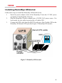
1
® RemotEye II User Manual Document Number: 50024-008 November, 2005 About This Manual This manual was written by the TOSHIBA Engineering and Marketing Groups. These groups are tasked with providing technical documentation for the RemotEye II system. Every effort has been made to provide accurate and concise information to you, our customer. This manual provides information on how to safely install, operate, and maintain your RemotEye II system. This manual includes a section of general safety instructions that describes the warning labels and symbols that are used throughout the manual. Read the manual completely before installing, operating, or performing maintenance on this equipment. The information in this manual is subject to change without notice. The Toshiba International Corporation shall not be liable for direct, indirect, special, or consequential damages resulting from the use of the information contained within this manual. This manual is copyrighted. No part of this manual may be photocopied or reproduced in any form without the prior written consent of the Toshiba International Corporation. TOSHIBA is a registered trademark of the TOSHIBA Corporation. RemotEye is a registered trademark of the Toshiba International Corporation. All other product or trade references appearing in this manual are registered trademarks of their respective owners. © Copyright 2005 Toshiba International Corporation. All rights reserved. 2 Contacting TOSHIBA’s Customer Support Center TOSHIBA’s Customer Support Center can be contacted to obtain help in resolving any RemotEye II system problem that you may experience or to provide application information. The Support Center can be reached at 800-231-1412 (toll free) or 713-466-0277. The center is open from 8 a.m. to 5 p.m. (CST), Monday through Friday. You may also contact TOSHIBA by writing to: TOSHIBA International Corporation 13131 West Little York Road Houston, Texas 77041-9990. For further information on TOSHIBA’s products and services, please visit our website at WWW.TIC.TOSHIBA.COM. 3 Important Notice This user manual may not cover all of the variations in equipment, nor may it provide information on every possible contingency concerning installation, operation, or maintenance. The contents of this manual shall not become a part of or modify any prior agreement, commitment, or relationship between the customer and the TOSHIBA International Corporation's UPS Division. The sales contract contains the entire obligation of the TOSHIBA International Corporation's UPS Division. The warranty contained in the contract between the parties is the sole warranty of the TOSHIBA International Corporation's UPS Division, and any statements contained herein do not create new warranties or modify the existing warranty. Any electrical or mechanical modifications to this equipment without prior written consent of the TOSHIBA International Corporation will void all warranties and may void the UL/CUL listing or other safety certifications. Unauthorized modifications may also result in equipment damage or personal injury. When used on UPS supporting safety critical equipment, carefully analyze the impact of allowing remote access of the UPS control features. 4 Table of Content About This Manual ....................................................................................................... 2 Contacting TOSHIBA’s Customer Support Center ...................................................... 3 Important Notice ........................................................................................................... 4 General Safety Instructions .......................................................................................7 Important Safety Instructions...................................................................................10 Introduction................................................................................................................. 12 Package Contents ....................................................................................................13 RemotEye II Features ..............................................................................................15 Installation .................................................................................................................. 17 System Compatibility ...............................................................................................17 Installing RemotEye II/Internal ...............................................................................18 Installing RemotEye II/External ..............................................................................19 Making the Network Connection .............................................................................20 Configuration.............................................................................................................. 21 Preliminary Issues ...................................................................................................21 Configuring the RemotEye II via Terminal..............................................................23 Connecting to the RemotEye II via Terminal...........................................................24 RemotEye II Configuration Menu Navigation .........................................................26 Configuring the RemotEye II via Telnet ..................................................................42 Connecting to the RemotEye II via Telnet ...............................................................44 RemotEye II Telnet Menu Navigation......................................................................44 Configuring the RemotEye II via HTTP...................................................................45 Connecting to the RemotEye II via HTTP...............................................................47 RemotEye II Web Menu Navigation.........................................................................48 Configuring the Remoteye II via SNMP...................................................................84 Connecting to the RemotEye II via SNMP...............................................................95 MIB ........................................................................................................................100 5 Toshiba RemotEye II Application Program.............................................................. 108 Toshiba RemotEye II Client Software....................................................................108 Auto Save-Log Software ........................................................................................123 Upgrade RemotEye II ............................................................................................128 Hardware Specifications ........................................................................................... 132 RemotEye II/Internal Hardware Specification ......................................................132 RemotEye II/External Hardware Specification......................................................135 Cables Definition ...................................................................................................137 6 General Safety Instructions DO NOT attempt to install, operate, maintain or dispose of this equipment until you have read and understood all of the product safety information and directions that are contained in this manual. Safety Alert Symbol The Safety Alert Symbol indicates that a potential personal injury hazard exists. The symbol is comprised of an equilateral triangle enclosing an exclamation mark. SIGNAL WORDS Listed below are the signal words that are used throughout this manual followed by their descriptions and associated symbols. When the words DANGER, WARNING and CAUTION are used in this manual they will be followed by important safety information that must be carefully adhered to. The word DANGER preceded by the safety alert symbol indicates that an imminently hazardous situation exists that, if not avoided, will result in death or serious injury to personnel. DANGER The word WARNING in capital letters preceded by the safety alert symbol indicates that a potentially hazardous situation exists that, if not avoided, could result in death or serious injury to personnel. 7 WARNING The word CAUTION or ATTENTION in capital letters preceded by the safety alert symbol indicates that a potentially hazardous situation exists which, if not avoided, may result in minor or moderate injury. CAUTION / ATTENTION The word CAUTION in capital letters without the safety alert symbol indicates a potentially hazardous situation exists which, if not avoided, may result in equipment and property damage. Special Symbols To identify special hazards, other symbols may appear in conjunction with the DANGER, WARNING and CAUTION signal words. These symbols indicate areas that require special and/or strict adherence to the procedures to prevent serious injury to personnel or death. Electrical Hazard Symbol A symbol which indicates a hazard of injury from electrical shock or burn. It is comprised of an equilateral triangle enclosing a lightning bolt. Explosion Hazard Symbol A symbol which indicates a hazard of injury from exploding parts. It is comprised of an equilateral triangle enclosing an explosion image. 8 Equipment Warning Labels DO NOT attempt to install, operate, maintain, or dispose of this equipment until you have read and understood all of the product warnings and user directions that are contained in this instruction manual. DO NOT remove or cover any of the labels. If the labels are damaged or if additional labels are required, contact your Toshiba representative for additional labels. Labels attached to the equipment are there to provide useful information or to indicate an imminently hazardous situation that may result in serious injury, severe property and equipment damage, or death if the instructions are not followed. 9 Important Safety Instructions This manual contains important instructions that should be followed during the installation, maintenance, and operation of the UPS and its batteries to assure safe and proper operation. Turn off, lockout, and tagout all power sources before connecting the power wiring to the equipment or when performing maintenance. Unauthorized personnel should not service batteries. Contact your nearest Toshiba authorized service center for battery replacement. Qualified Personnel ONLY! Qualified Personnel is one that has the skills and knowledge relating to the construction, installation, operation, and maintenance of the electrical equipment and has received safety training on the hazards involved (Refer to the latest edition of NFPA 70E for additional safety requirements). Qualified Personnel shall: Have read the entire operation manual of the system being serviced. Be trained and authorized to safely energize, de-energize, ground, lockout and tag circuits and equipment, and clear faults in accordance with established safety practices. Be trained in the proper care and use of protective equipment such as safety shoes, rubber gloves, hard hats, safety glasses, face shields, flash clothing, etc., in accordance with established safety practices. Be trained in rendering first aid. Be knowledgeable of batteries and the required handling and maintenance precautions. 10 WARNING Misuse of this equipment could result in injury and equipment damage. In no event will Toshiba Corporation be responsible or liable for either indirect or consequential damage or injury that may result from the misuse of this equipment. CAUTION Installation Precautions Install the unit in a well-ventilated location; allow at least 10 cm (4 inches) on all sides for air ventilation and for maintenance. Install the unit in a stable level and upright position that is free of excessive vibration. Install the unit where the ambient temperature is within the specified range. Do not install the unit in areas that are subject to high humidity. Do not install the unit in areas that allow exposure to direct sunlight. Do not install the unit in areas that allow exposure to high levels of airborne dust, metal particles, or flammable gases. Do not install the unit in areas near sources of electrical noise. Ensuring a proper earth ground will reduce the effects of electrical noise and will reduce the potential for electrical shock. Do not install the unit in areas that would allow fluids or any foreign object to get inside the unit. For further information on workplace safety visit www.osha.gov. 11 Introduction Congratulations on the purchase of your new Toshiba Uninterruptible Power Supply (UPS) system management tool: the RemotEye II! The RemotEye II supplies a 10/100 base-T network card that allows network administrators to monitor and control Toshiba UPS systems remotely via Simple Network Management Protocol (SNMP) and Hypertext Transfer Protocol (HTTP) methods. This user manual describes the configuration and operation of the RemotEye II. The RemotEye II is available as a circuit board that is inserted into the option slot of the UPS or as an external device that connects to the UPS via a provided cable. The RemotEye II/Internal is designed for the Toshiba UPS that has the option slot. The circuit board is connected to the UPS via the RemotEye II/Internal card edge connector. The RemotEye II/External is designed primarily for use with the Toshiba UPS that does not have the extension option slot, but it may also be used in a UPS system that has an extension option slot. The RemotEye II/External communicates with the UPS via a provided cable. 12 Package Contents Listed below are the items included in the RemotEye II/Internal and RemotEye II/External packages. RemotEye II/Internal Contents The RemotEye II/Internal printed circuit board and bracket for securing the board within the UPS extension slot. A CD-ROM containing the following: Toshiba.mib, the Toshiba version 1.2 MIB file (RFC1628-compatible), Tupgrade.exe, the RemotEye II upgrade utility, Tsb3xx.bin, the Current RemotEye II image file, Window.exe, Toshiba RemotEye II Client Software installation file for Window, Unix.exe, Toshiba RemotEye II Client Software installation file for UNIX OS, and RemotEye II User Manual in PDF format. PC cable, a DB9 female to RJ45 cable (Workstation COM port to RemotEye II/Internal COM port). The RemotEye II User Manual. 13 RemotEye II/External Contents The RemotEye II/External device. A power adapter. A CD-ROM containing the following: Toshiba.mib, the Toshiba version 1.2 MIB file (RFC1628-compatible), Tupgrade.exe, the RemotEye II upgrade utility, Tsb3xx.bin, the Current RemotEye II image file, Window.exe, Toshiba RemotEye II Client Software installation file for Window, Unix.exe, Toshiba RemotEye II Client Software installation file for UNIX OS, and RemotEye II User Manual in PDF format. PC cable, a DB9 female to RJ45 cable (Workstation COM port to RemotEye II/External PC port). UPS cable, a DB9 male to RJ45 cable (Toshiba UPS RS232 port to RemotEye II/External UPS port). The RemotEye II User Manual. 14 RemotEye II Features Included in the RemotEye II are several support options for managing Toshiba UPS. BOOTP/DHCP Requests The RemotEye II can automatically retrieve its network identity from a network server using the Boot Protocol (BOOTP) or Dynamic Host Configuration (DHCP) automatic configuration technique. HTTP Web Access Web access includes Secure Sockets Layer (SSL) Configurations. This allows users to access data from RemotEye publicly or privately using the web. Telnet, Terminal Access Telnet includes Secure Shell (SSH) protocol configuration. SNMP Access RemotEye II provides enhanced SNMP security with option of SNMPv3, default protocol is SNMPv1. It is compatible with the United States Standard UPS MIB, RFC1628 and also with Japanese Standard UPS MIB. Additional features of the RemotEye II include: Real-Time Clock The RemotEye II contains its own RTC. This clock is used for time-stamping of its data log and for executing any scheduled events. UPS Event Notification RemotEye II sends out notification of UPS events via Email, SNMP Traps and Java Applets. Graphic User Interface (GUI) User-friendly GUI for web pages and Java applets Power Quality Monitor Java applets provide on-screen visual indication of power quality through dynamic graphics. Versatile Remote UPS Management Allows monitoring of the UPS via SNMP and HTTP communication. Also provides Java monitoring applets accessible through an internet browser. Versatile UPS Configuration RemotEye II has the ability to set the UPS parameters from any SNMP management station or through internet web browsers using HTTP forms and objects. 15 Data Log Retention RemotEye II stores history file containing UPS power events, power quality, UPS status, and battery condition in non-volatile memory. Automatic UPS Shutdown The Toshiba RemotEye II Client Software provides unattended and on-demand UPS shutdown; either pre-programmed by the administrator or when the UPS reports a low battery condition. RemotEye II also supports the following external applications: Network Upgrade Tupgrade.exe, a network upgrade utility, allows user to upgrade to a newer version of the RemotEye. Auto Save Log This utility allows users to save logs from several RemotEye(s) at the same time to a same or different computer. Client Shutdown The Toshiba RemotEye II Client Software can broadcast system failure messages via an IP (Internet Protocol) packet and perform unattended shutdown of multiple servers operating under a variety of platforms. Environmental Monitoring Device (EMD) (Optional) EMD allows monitoring of the environment temperature and humidity. Also provides 2 contact closures. 16 Installation System Compatibility The RemotEye II is supported by workstations using the following operating systems: Windows 95/98/NT/2000/XP, Macintosh, and Unix. The RemotEye II supports the following Toshiba UPS system families: 1000 Series 1400 S(E) (Plus), 1400 XL Plus, 1400 Super XL Plus Series, 1500 (Plus) Series, 1600 (Plus) Series, 1700 (Plus) Series, 4200 (Plus) Series, and G8000 Series. 17 Installing RemotEye II/Internal Follow these steps to install the RemotEye II/Internal card. 1. 2. 3. Turn the UPS off using the proper shutdown procedure as explained in the UPS manual. Slide the RemotEye II/Internal printed circuit board into the extension option slot of the UPS. Secure the printed circuit board using the UPS supplied screws.(See Figure 1: RemotEye II/Internal) Figure 1: RemotEye II/Internal 18 Installing RemotEye II/External Follow these steps to install the RemotEye II/External device. 1. 2. 3. Insert the power adapter cable of the RemotEye II into the 12 VDC power receptacle of the RemotEye II device. Plug the RemotEye II power adapter into a 120/220 VAC power source. For best results, be sure outlet is powered by a Toshiba UPS. Connect the UPS cable from the RS232 serial port of the Toshiba UPS to the RemotEye II/External UPS port.(See Figure 2: RemotEye II/External) Figure 2: RemotEye II/External 19 Making the Network Connection Each Ethernet network is different. Therefore, the following steps should be used as an outline for connecting the RemotEye II to a network: 1. 2. 3. 20 Connect one end of a Category 5 cable to the NETWORK RJ45 receptacle of RemotEye II. Connect the other end of the Category 5 cable to a designated network switch or hub. A network administrator will allocate an available port. Verify a network link has been established. On RemotEye II/External, confirm Traffic LED on RemotEye II is illuminated. On RemotEye II/Internal, confirm the leftmost, green LED is illuminated. Configuration RemotEye II must be configured for proper operation on its network. The RemotEye II offers three convenient methods for configuration. Preliminary Issues RemotEye II is a network device. Several items should be considered prior to communicating with RemotEye II over the network. The following sections cover important topics when placing a device on an Ethernet network. MAC Address The Media Access Control (MAC) address is an identification number which uniquely identifies each Ethernet device on a network. The MAC address (sometimes called the physical address) is made up of 6 hexadecimal bytes. A label marked with the MAC address is included with each RemotEye II. This label is affixed to the bottom of every RemotEye II /External, and this label is affixed to the top of every RemotEye II /Internal printed circuit board. For each RemotEye II, the MAC address is created using the following format: 00 E0 D8 LL MM NN. The first half of this code, 00 E0 D8, identifies the manufacturer of the Ethernet board. Since every RemotEye II is produced by the same manufacturer, these 3 hexadecimal bytes remain constant. The LL MM NN characters identify the serial number of the device in hexadecimal form. The serial number is unique for each RemotEye II device. 21 Default IP Address The RemotEye II is initially configured with a default Internet Protocol (IP) address. By default, the 4 bytes composing the default IP address are derived from the MAC address in the following way: 172.18.xxx.yyy where xxx is the decimal value of the MM MAC address byte and yyy is the decimal value of the NN MAC address byte. Example: A RemotEye II MAC address of 00 E0 D8 0C 01 3F would have a default IP address of 172.18.1.63. This places RemotEye II on a 172.18.0.0 IP network. Default Network Mask The RemotEye II is initially configured with a default Network Mask. This default value is always: 255.255.0.0. This places RemotEye II on a Class B network. Default Gateway The RemotEye II is initially configured with a Gateway address of 0.0.0.0. This value indicates RemotEye II will not attempt to use a gateway when transmitting. 22 Configuring the RemotEye II via Terminal The RemotEye II can be configured by directly connecting to the device. Hardware Setup Direct configuration is accomplished through the provided cable. Follow these steps to setup the hardware for direct RemotEye II configuration: Connect the DB9 female end of the PC cable to the terminal or workstation COM port. Connect the RJ45 end of the PC cable to the PC port of RemotEye II/External or the COM port of the RemotEye II/Internal. Software Setup The direct configuration is accomplished by using the RS232 communication protocol. The direct communication can be performed from a workstation running Terminal Emulator Software (TES) 23 Connecting to the RemotEye II via Terminal A direct configuration session can easily be established once the hardware and software are properly set up. Follow these steps to begin configuration: Terminal Emulator Example To configure the RemotEye II from a Windows platform, use Hyperterminal. Hyperterminal is a standard terminal emulator packaged with any Windows operating system. Launch the Hyperterminal program by navigating to Start →Programs →Accessories →Hyperterminal →Hyperterminal, and follow the prompts. Enter a name and select an icon for the application at the Connection Dialog box. Select a direct connection to an appropriate com port listed in the pull-down menu. Ensure that the Properties dialog box is setup according to preceding . Baud Rate — 9600 Data Bits — 8 Parity — None Stop Bits — 1 Flow Control —- None Press [Enter] and the RemotEye II version and Password field will be displayed (see Figure 3: Console Login Screen). Enter the password (default is “public”) and press [Enter] to display the RemotEye II Main Menu. +====================================================================+ | [ TIC RemotEye II Login Menu ] | +====================================================================+ Enter Password: ****** Figure 3: Console Login Screen 24 The seven options provided in the RemotEye II Main Menu provide access to all system RemotEye II configuration parameters. These options (see the Main Menu Description on Figure 4: Console Main Menu) and their submenus are discussed in more detail in the next section. +====================================================================+ | [ TIC RemotEye II Main Menu ] | +====================================================================+ 1. TIC RemotEye Configuration 2. SNMP Communities 3. SNMPV3 USM Table 4. Trap Receiver Table 5. Reset Configuration To Default 6. Save and Exit 7. Save and Restart Agent Please Enter Your Choice => Figure 4: Console Main Menu 25 RemotEye II Configuration Menu Navigation The main menu of the RemotEye II provides access to configuration parameters. The table below (table 1) provides an overview of the entire menu structure. When navigating through these menus, all alpha-numeric characters are acceptable and are case-sensitive. RemotEye II Main Menu (1) Toshiba RemotEye (1) System Group II Configuration RemotEye II Agent Version Ethernet Address (1) IP Address (2) Gateway Address (3) Network Mask (4) System Date and Time (0) Return to Previous Menu (2) Control Group (1) HTTP Login Username (2) Community Read-On1y (3) Community Read/Write (4) BOOTP/DHCP Control (5) Telnet Control (6) Network Upgrade Control (7) HTTP Security Control (8) SNMP Version Control (0) Return to Previous Menu (3) Parameter Group (1) System Contact (2) System Name (CID) (3) System Location (4) Poll Rate (0) Return to Previous Menu (4) Email Group (1) Mail Server (2) User Account (3) User Password (4) Domain Name (5) DNS IP Address (6) Daily Status Report 26 (4) EMD Group (2) SNMP Communities (3) SNMPV3 USM Table (4) Trap Receiver Table (7) Mail Receivers (8) Test Email Configuration (0) Return to Previous Menu (1) Temperature Group (2) Humidity Group (3) Alarm-1 Group (4) Alarm-2 Group (5) Devide Status (0) Return to Previous Menu (1) Modify Table Entry (2) Reset to Default Setting (0) Return to Previous Menu (1) Modify Table Entry (2) Reset to Default Setting (0) Return to Previous Menu (1) Modify Table Entry (2) Reset to Default Setting (0) Return to Previous Menu (5) Reset Configuration to Default (6) Save and Exit (7) Save and Restart Agent Table 1: Menu Map for RemotEye II Console 27 Main Menu Description The Main Menu of the RemotEye II consists of the following options (see Figure 5: Console Main Menu Description): 1. Toshiba RemotEye II Configuration 2. SNMP Communities 3. SNMPv3 USM Table 4. Trap Receiver Table 5. Reset Configuration to Default. 6. Save and Exit. 7. Save and Restart Agent. Press the number of the associated selection and press Enter. +====================================================================+ | [ TIC RemotEye II Main Menu ] | +====================================================================+ 1. TIC RemotEye II Configuration 2. SNMP Communities 3. SNMPV3 USM Table 4. Trap Receiver Table 5. Reset Configuration To Default 6. Save and Exit 7. Save and Restart Agent Please Enter Your Choice => Figure 5: Console Main Menu Description 28 Toshiba RemotEye II Configuration Main Menu →(1)Toshiba RemotEye II Configuration (see Figure 6: Console Configuration Menu Description). The Toshiba RemotEye II Configuration option provides access to the following system settings: 1. 2. 3. 4. 5. 0. System Group Control Group Parameter Group Email Group EMD Group Return to Previous Menu +==================================================================+ | [ TIC RemotEye II Configuration Menu ] | +==================================================================+ 1. System Group 2. Control Group 3. Parameter Group 4. Email Group 5. EMD Group 0. Return to previous menu Please Enter Your Choice => Figure 6: Console Configuration Menu Description 29 System Group Main Menu →Toshiba RemotEye II Configuration →(1)System Group (see Figure 7: Console System Group Menu Description). The System Group provides access to the system settings listed below. The settings may be viewed or changed from this screen. When using the Dynamic Host Configuration Protocol (DHCP), items 1 – 3 will be retrieved automatically. 1. 2. 3. 4. 0. IP Address — RemotEye II IP address. Gateway Address — The gateway IP address (if a router is necessary). Network Mask — The network mask for the RemotEye II network. Date and Time — The RemotEye II date in the MM/DD/YYYY format The RemotEye II time in the HH:MM:SS format. RemotEye II supports the Network Time Protocol (NTP) and NTP Time Zone features. These two features enable the UPS to synchronize its date and time with a NTP server and with the options of daylight saving time control. (see Figure 8: Date & Time Menu Description). Return to Previous Menu. +====================================================================+ | [ System Group Menu ] | +====================================================================+ RemotEye II Agent Version : TIC RemotEye II v3.00 Ethernet address : 00 E0 D8 08 80 0D 1. Ip Address : 172.18.1.63 2. Gateway Address : 172.18.1.1 3. Network Mask : 255.255.240.0 4. Date and Time 0. Return to previous menu Please Enter Your Choice => Figure 7: Console System Group Menu Description 30 +=================================================================+ | [ Date and Time Menu ] | +=================================================================+ 1. System Date (dd/mm/yyyy) : 09/24/2005 2. System Time (hh:mm:ss) : 12:22:21 3. NTP Server : 0.0.0.0 4. NTP Time Zone : -06:00 5. Daylight Saving Time Control : Enabled 6. NTP Control : Enabled 0. Return to previous menu Please Enter Your Choice => Figure 8: Date & Time Menu Description 31 Control Group Main Menu →Toshiba RemotEye II Configuration → (2)Control Group (see Figure 9: Console Control Group Menu Description on page 33) The Control Group menu provides access to the system settings listed below. The settings may be viewed and changed from this screen. 1. 2. 3. 4. 5. 6. 7. 8. 9. 32 HTTP Login User Name — The login user name grants write access from a web browser (the default setting is TOSHIBA). Community Read-Only — This common community name provides readonly access to devices within this community. (The default setting is public.) Community Read/Write — This common community name provides read and write access to devices within this community. (The default setting is public.) This value is equivalent to the terminal/telnet login password. BOOTP/DHCP Control — This parameter is used to enable or disable the BOOTP/ DHCP requests from RemotEye II. (The default setting is Enabled). Telnet Control — This parameter is used to enable or disable remote RemotEye II configuration through telnet applications. (The default setting is Enabled). Network Upgrade Control — This parameter is used to enable or disable the Trivial File Transfer Protocol image upgrade. When disabled, RemotEye II will block any attempts to upgrade. ( The default setting is Disabled.) HTTP Security Control — This parameter is used to enable or disable the web password protection feature. When enabled, a password is required to access RemotEye II through the web, and write privileges are automatically assumed. When disabled, any machine can access RemotEye II over the web, but a password is required prior to assuming write privileges. (The default setting is Disabled.) SNMP Version Control —This parameter is used to enable and disable the Simple Network Management Protocol security level. When enable, administrators has the options to set for SNMPv1 or SNMPv3. Return to Previous Menu +====================================================================+ | [ Control Group Menu ] | +====================================================================+ 1. HTTP Login Username : TOSHIBA 2. Community Read-Only : public 3. Community Read/Write : * 4. BOOTP/DHCP Control : Enabled 5. Telnet Control : Enabled 6. TFTP Upgrade Control : Disabled 7. HTTP Security Control : Disabled 8. SNMP Version Control : Disabled 0. Return to previous menu Please Enter Your Choice => Figure 9: Console Control Group Menu Description 33 Parameter Group Main Menu →Toshiba RemotEye II Configuration →(3)Parameter Group (see Figure 10: Console Parameter Group Menu Description) The Parameter Group provides access to the system settings listed below. The settings may be viewed or changed from this screen. 1. 2. 3. 4. 0. System Contact — The RemotEye II system administrator. (The default setting is TIC Local Technical Support.) System Name — The alias of the RemotEye II. This string serves as the RemotEye II Client Identifier (CID) in DHCP systems. System location — The RemotEye II physical location. Poll Rate — The polling rate in seconds. This determines how frequently RemotEye II updates its data from the Toshiba UPS. (The default setting is 5.) Return to previous menu. +====================================================================+ | [ Parameter Group Menu ] | +====================================================================+ 1. System Contact : TIC Local Technical Support 2. System Name : RemotEye II 3. System Location : 4. Poll Rate : 5 0. Return to previous menu Please Enter Your Choice => Figure 10: Console Parameter Group Menu Description 34 Email Group Main Menu → (1)Toshiba RemotEye II Configuration → (4)Email Group (see Figure 9: Console Control Group Menu Description on page 36) The Email Group menu provides access to the system settings listed below. The settings may be viewed and changed from this screen. 1. Mail Server — The Simple Mail Transfer Protocol (SMTP) mail server IP address. If a hostname is used, such as smtp.tic.toshiba.com, the Domain Name Server (DNS) IP address is required on setting #4. 2. User Account — The user account login name for the SMTP mail server. 3. User Password — The user account password for the SMTP mail server. Note: Not all servers require login name and password, please check with SMTP administrator. 4. 5. Domain Name — The domain Name of the mail server. DNS IP Address — Domain Name Server IP address is required if a hostname is used for Mail Server. Otherwise, this field can be 0.0.0.0. 6. Daily Status Report — This parameter is used to set the time to send RemotEye II daily status report 7. Mail Receivers — RemotEye II sends email notification to four recipients. The recipients include users who use Short Message System (SMS) in Email address format, such as [email protected] Mail Account — This parameter is used to enter the recipients’ email Address Mail Type 1. None – Disable option to send email to recipients. 2. Events – Current events will be sent to recipients 3. Daily Status – Daily History log and Events log will be sent to the email recipients at the designated time. 4. Events with Status – Current events, History log and Events log will be sent to email recipients when events occurred. 8. Test Email Configuration — This parameter is used to perform instant email test. If instant email is not received after the test, please check the configuration. 35 +===================================================================+ | [ Email Group Menu ] | +===================================================================+ 1. Mail Server : 2. User Account : 3. User Password : * 4. Domain Name : 0 5. DNS IP Address : 0.0.0.0 6. Daily Status Report : 00:00 7. Mail Receivers 8. Test Email Configuration 0. Return to previous menu Please Enter Your Choice => Figure 11: Console Email Group Menu Description 36 EMD Group Main Menu →Toshiba RemotEye II Configuration → (5)EMD Group (see on page) The EMD Group menu provides access to the system settings listed below. The settings may be viewed and changed from this screen. Temperature Group — The Temperature Group provides the options to setup the low and high warning and critical points. Users also have the options to setup the hysteresis and calibration offset from this group. Humidity Group — The Humidity Group provides the options to setup the low and high warning and critical points. Users also have the options to setup the hysteresis and calibration offset from this group.. Alarm-1 Group — The Alarm-1 Group provides the option to setup this dry contact as normal close, normal open, high active, low active and disabled. Alarm-2 Group — The Alarm-2 Group provides the option to setup this dry contact as normal close, normal open, high active, low active and disabled. Device Status — The Device Status provides the options of disabled and auto. Auto will enable the RemotEye II to auto detect the EMD that connected to it PC port. +================================================================+ | [ EMD Group Menu ] | +================================================================+ 1. Temprature Group 2. Humidity Group 3. Alarm-1 Group 4. Alarm-2 Group 5. Device Status : Auto 0. Return to previous menu Please Enter Your Choice => Figure 12: Console EMD Group Menu Description 37 SNMP Communities Main Menu →(2)SNMP Communities (see Figure 13: SNMP Communities Description). The SNMP Communities lists the status and configuration of access rights that are currently granted and the applicable level of access. The entries in this table are largely responsible restricting SNMP communication with RemotEye II. The configuration of the SNMP communities shall be as follows: IP Address: IP address of the NMS Community String: NMS Get/Set Community String (Please refer to SNMP Get/Set Criteria on page 95 for a more detailed explanation on Get/Set.) Access: Select Access Type: 1. Read Only 2. Read/Write 3. NoAccess +====================================================================+ | IP Address Community String Access | +====================================================================+ [1] 0.0.0.0 * No Access [2] 0.0.0.0 * No Access [3] 0.0.0.0 * No Access [4] 0.0.0.0 * No Access [5] 0.0.0.0 * No Access [6] 0.0.0.0 * No Access [7] 0.0.0.0 * No Access [8] 0.0.0.0 * No Access COMMANDS 1. Modify - Modify an entry of table 2. Reset - Reset an entry to default from table 0. Return to previous menu Please Enter Your Choice => Figure 13: SNMP Communities Description 38 SNMPv3 USM Table Main Menu →(3)SNMPv3 USM Table (seeFigure 14: SNMPv3 USM Menu Description). The SNMPv3 USM Table lists the status and configuration of access rights that are currently granted and the applicable level of access. The entries in this table are largely responsible restricting SNMPv3 security with RemotEye II. The configuration of the SNMPv3 USM table shall be as follows: User Name: The User ID for the authorized individual. Authentication Passowrd: The password string for the authorized individual. Privacy Passowrd: The privacy password string for the authorized individual. Security: The security level provides the following 3 options: 1. noAuthNoPriv – with no authentication and no privacy passwords 2. authNoPriv - with authentication password but no privacy password 3. authPriv – with no authentication password but with privacy password Authentication format: The authentication format provides the following options: 1. HMAC-MD5 2. HMAC-SHA Status Type: The status shows the authentication status, Ready or not being used. +====================================================================+ | User Name Authentication. Password Privacy Password | | Security Authentication Format Status Type | +====================================================================+ [1] noAuthNoPriv HMAC-MD5 Not Use [2] noAuthNoPriv HMAC-MD5 Not Use [3] noAuthNoPriv HMAC-MD5 Not Use [4] noAuthNoPriv HMAC-MD5 Not Use COMMANDS 1. Modify - Modify an entry of table 2. Reset - Reset an entry to default from table 0. Return to previous menu Please Enter Your Choice => Figure 14: SNMPv3 USM Menu Description 39 Trap Receiver Table Main Menu →(3)Trap Receiver Parameters (see Figure 15: Console Trap Receiver Table Description). The Trap Receiver Table lists IP addresses of the administrative machines that have been assigned to receive traps. The configuration of the trap receivers shall be as follows: IP Address: IP address of the NMS. Community String: NMS community string. Select Trap Type: 3. None 4. Toshiba Trap 5. JEMA Trap Description: Description of the NMS. +====================================================================+ | IP Address Community String Trap-Type Description | +====================================================================+ [1] 0.0.0.0 * [2] 0.0.0.0 * [3] 0.0.0.0 * [4] 0.0.0.0 * [5] 0.0.0.0 * [6] 0.0.0.0 * [7] 0.0.0.0 * [8] 0.0.0.0 * 1. Modify - Modify an entry of table 2. Reset - Reset an entry to default from table 0. Return to previous menu Please Enter Your Choice => Figure 15: Console Trap Receiver Table Description 40 Reset Configuration to Default Main Menu →(4) Reset Configuration to Default. Selecting this option restores all RemotEye II card settings to its original default values. From the Main Menu, press 4 to access the Reset Configuration to the Original Setting screen. Save and Exit Main Menu →(5)Save and Exit. When executed, the system saves the RemotEye II configuration and exits the program. The new configuration takes effect immediately. Save and Restart Agent Main Menu →(6) Save and Restart Agent. When executed, the system saves the RemotEye II configuration and restarts the RemotEye II. 41 Configuring the RemotEye II via Telnet The RemotEye II can be configured by establishing a telnet session with the device. Hardware Setup Telnet configuration is accomplished through a network link. Follow these steps to setup the hardware for telnet RemotEye II configuration: Verify network cable connection to NETWORK port of RemotEye II. Verify active link to LAN or Network. For further information on the network connection, refer to Making the Network Connection on page 20. Software Setup The telnet configuration is accomplished through a TCP/IP network connection. A telnet connection can be established with RemotEye II by using any telnet application. Follow these steps to setup the software for telnet RemotEye II configuration: Verify workstation is loaded with Telnet application. Verify a valid network path exists between the RemotEye II and the workstation. If performing the telnet configuration from a workstation that is located on the same network, then proceed to the next section to the section, Connecting to the RemotEye II via Telnet on page 44, otherwise, continue with the next section Routing to the RemotEye II on page 43. 42 Routing to the RemotEye II If the workstation is not on the same network as the RemotEye II, the system may require the addition of a network route. This is typically only necessary when RemotEye II is using its default address. Consult operating system documentation pertaining to the addition of network routes for instruction. Example Route Addition Windows operating systems provide the command Route Add for adding network routes. Assume the default IP Address of the RemotEye II is 172.18.1.63, and assume the IP Address of the workstation is 210.67.192.147. To add the appropriate network route between these two devices, follow these steps: Turn on the workstation, and setup the TCP/IP protocol (if necessary). Enter the following command to add a routing condition: Route add 172.18.1.63 210.67.192.147 See the Windows manual for further information on how to add a routing condition to a workstation. 43 Connecting to the RemotEye II via Telnet A telnet configuration session can be established once the hardware and software are prepared. Follow these steps to begin configuration: 1. Type telnet followed by the IP address of RemotEye II at a Unix console or a DOS prompt. 2. Press [Enter]. 3. Key in the password (default is public) when prompted. For more information on using telnet, please refer to telnet application Windows help file or Unix man page. The RemotEye II will only accept 2 telnet clients simultaneously. The telnet connection will time-out after 60 seconds of inactivity. RemotEye II Telnet Menu Navigation The configuration menus for telnet configuration are identical to those presented by a direct configuration session. Refer to page 26 for detailed guidance through configuration menus of RemotEye II. 44 Configuring the RemotEye II via HTTP The RemotEye II can be configured by opening a web session with the device. Hardware Setup Web configuration is accomplished through a network link. Follow these steps to prepare the hardware for HTTP RemotEye II configuration: 1. 2. 3. Verify network cable connection to NETWORK port of RemotEye II. Verify active link to LAN or Network. For further information on the network connection, refer to Making the Network Connection on page 20. Software Setup The web configuration is accomplished through a TCP/IP network connection. A web connection can be established with RemotEye II by using any Internet Browser application (for example, Netscape). Follow these steps to setup the software for web-based RemotEye II configuration: 1. 2. Verify workstation is loaded with web browser application. Verify a valid network path exists between RemotEye II and the workstation. If performing the web configuration from a workstation that is located on the same network, then proceed to the next section; otherwise, refer back to the section entitled Routing to the RemotEye II on page 43. 45 System Setup To access the RemotEye II via the web, enter the IP address of the RemotEye II in the URL field of the browser and press Enter. If unable to access the RemotEye II due to a firewall, contact the network administrator for information on bypassing the firewall of the LAN. The HTTP Security Control setting may also affect the user’s ability to access the RemotEye II. The HTTP Security Control setting may be set or viewed from: Main Menu →(1)TIC RemotEye II Configuration →(2) Control Group → (7) HTTP Security Control. If the HTTP Security Control setting is Disabled, the user is granted read-only access. If the HTTP Security Control is Enabled, any attempt to access RemotEye II pages will be met with a request to enter a password. Once the password has been entered in the user will be able to not only view the information, but make changes accordingly. The password is the same as the Community Read/Write string (see Main Menu →(1)Toshiba RemotEye II Configuration →(2) Control Group → (3) Community Read/Write). Once access to the RemotEye II is achieved, refer to this section for information on how to use the web-based administration interface to monitor and maintain the RemotEye II. This section also provides information on the built-in administrative functions of the RemotEye II. To prevent unauthorized users from configuring the RemotEye II via HTTP, the IP address of the workstation must be entered in the RemotEye II SNMP Communities with no access permissions (via RS232 or Telnet) or the SNMP/ HTTP Access Control (via Web Browser) of the RemotEye II. Otherwise, the RemotEye II will provide only read access to its parameters. 46 Connecting to the RemotEye II via HTTP A web session can be established once the hardware and software have been prepared. Follow these steps to begin configuration: 3. 4. Launch the web browser. Enter the URL for RemotEye II in the browser’s address field. For example, http://172.18.1.63. The home page of the RemotEye II will be displayed once a connection is established (see Figure 16: RemotEye II HTTP Page on page 48). Perform the following procedure to setup the RemotEye II using its provided web configuration pages. 1. 2. 3. 4. 5. 6. 7. 8. 9. 10. 11. Select RemotEye II Management → RemotEye II Configuration to configure RemotEye II. Click the Become Super User button at the bottom of the screen. Enter TOSHIBA as the login name and public as the password (case sensitive). Non-DHCP users continue on to step b. DHCP users may skip steps b to d. Enter the RemotEye II IP address. Enter the RemotEye II Gateway address in the network. Enter the RemotEye II Network Mask of the network. Enter the IP address of the Primary Time Server and Secondary Time Server in the network. Click Set Value to save the settings. Select RemotEye II Management →Date and Time to set date and time. Enter the appropriate date and time in the specified format. Click Set Value to save the settings. Select RemotEye II Management → RemotEye II Control to enable or disable the network protocols. 47 Figure 16: RemotEye II HTTP Page RemotEye II Web Menu Navigation The RemotEye II home page is comprised of Six primary menus: • UPS Monitoring, • UPS Management • Email Notification • EMD Configuration, • RemotEye II Management, and • UPS History. The six primary menus provide access to UPS and RemotEye monitoring and control functions, and each is discussed in detail in the following sections. 48 UPS Monitoring This menu allows the user to view the collected data from the UPS measurements. The UPS measured parameters are listed below and are allowed only to be read. UPS Comprehensive View This page lists the UPS parameters. This page will refresh automatically at a userdefined rate. To change or view the refresh rate setting, select RemotEye II Management - HTTP Page Refresh Rates. UPS Mode This field shows the present UPS system mode. These readings include: Other, None, On-Line, Bypass, Battery, Testing, and Output Shutdown. Input Voltage This field shows the present UPS input voltage in VAC. Output Voltage This field shows the present UPS output voltage in VAC. Output Load This field shows the present UPS load in % of kVA. Battery Capacity Remaining (option) This field shows the present remaining battery capacity expressed as a percentage of the battery's full capacity. Battery Temperature (option) This field shows the present UPS battery temperature in oC. Input Frequency This field shows the present UPS input frequency in Hz. Output Frequency This field shows the present UPS output frequency in Hz. Date on RemotEye II This field shows the RemotEye II date setting. This value is displayed in the mm/dd/yyyy format. Time on RemotEye II This field shows the RemotEye II time setting. This value is displayed in the hh:mm:ss 24-hour format (i.e. 8:30 p.m. is 20:30:00). 49 UPS Identification This page allows the user to retrieve the UPS identification and revision information. UPS Model This field shows the model name of the UPS (i.e., 1600 Series 8kVA 240/208/120Vac USA)to which RemotEye II is presently attached . UPS Name This field shows the administrator-configured name of the UPS. For configuration, please refer to UPS Configuration menu. UPS Firmware Revision This field shows the revision of the UPS firmware. UPS RemotEye II Agent Revision This field shows the revision of RemotEye II. UPS Manufacturer This field shows the name of the UPS manufacturer. UPS Attached Devices This field shows the administrator configured description of the load devices that attached to the UPS (e.g. computers, communication devices, etc). For configuration, please refer to UPS Configuration menu. UPS Serial Number This field shows the UPS manufactured serial number for the UPS which RemotEye II is presently attached. 50 Battery Parameters This page provides the battery status and battery run-time information. This page will refresh automatically at a user-defined rate. To change or view the refresh rate setting, select RemotEye II Management - HTTP Page Refresh Rates. Battery Status This field shows the status of the UPS batteries. These readings include: Unknown, Normal, Low, Depleted, Discharging, and Failure. Elapsed Time On Battery Power This field shows the elapsed time (in seconds) since the UPS switched to battery power. Battery Capacity Remaining (option) This field shows the remaining battery capacity expressed as a percentage of full capacity. Battery Estimated Minutes Remaining (option) This field shows the remaining minutes of the UPS to sustain the current load. Battery Voltage This field shows the battery voltage in VDC. Battery Voltage Percent This field shows the battery voltage in %. Battery Current (option) This field shows the present battery current in %. Battery Temperature (option) This field shows the internal UPS temperature expressed in oC. Battery Last Replaced Date This field shows the last replacement date of the UPS system's batteries. This value is displayed in the dd/mm/yyyy format. When the UPS batteries are replaced, this value should be adjusted accordingly by the service center. Battery Life Remaining This field shows the remaining battery life. The maximum battery lifetime is 5 years. This shows the remaining battery lifetime in months. Battery Rated Backup Time This field allows the administrator to configure the estimated battery backup time (in minutes) during power failure at 100% load. The default is 0 minutes. 51 Input Parameters This page shows the UPS line voltage input readings. This page will refresh automatically at a user-defined rate. To change or view the current refresh rate setting, select RemotEye II Management - HTTP Page Refresh Rates.. Input Voltage This field shows the UPS input voltage in VAC. Max. Input Voltage During Last 60 Seconds This field shows the maximum UPS input voltage during the last 60 seconds. Min. Input Voltage During Last 60 Seconds This field shows the minimum UPS input voltage during the last 60 seconds. Input Current (option) This field shows the present UPS input current in Amps. Input Active Power (option) This field shows the present UPS input active power in Watts. Input Frequency This field shows the UPS input frequency in Hz. 52 Output Parameters This page shows the UPS output voltage source and readings. This page will refresh automatically at a user-defined rate. To change or view the current refresh setting, select RemotEye II Management - HTTP Page Refresh Rates.. Output Status This field shows the status of the output. These readings include: Other, None, OnLine, Bypass, Battery and Output Shutdown. Output Voltage This field shows the UPS output voltage in VAC. Output Load This field shows the UPS load as a percentage of the maximum load setting. Output Active Power This field shows the present UPS output active power in Watts Output Apparent Power This field shows the present UPS apparent power in VA Output Power Factor (option) This field shows the present UPS power factor. Output Frequency This field shows the present UPS output frequency in Hz. 53 Alarm Table This page provides past and active UPS alarm activity and descriptions. This page will refresh automatically at a user-defined rate. To change or view the refresh rate setting, select RemotEye II Management - HTTP Page Refresh Rates. Number of Present Alarms This field shows the number of active UPS alarms. Lastest Alarm This field shows the last recorded UPS alarm. Alarm ID This field shows the sequential number associated with the alarm; it indicates the activation sequence of the alarms. This number will be reset after a RemotEye II reboot. Alarm Time This field shows the RemotEye II alarm time stamp. This value is displayed in the hh:mm mm/dd/yyyy format. Note: The time depends on the RemotEye II clock setting. Alarm Description This field shows the UPS alarm description. Please refer .Table 2: UPS Alarm Table for detail description. 54 Connected Client Table This page lists the protected registered clients of the RemotEye II that are running during the execution of the RemotEye II Shutdown application. This page will refresh automatically at a user-defined rate. To change or view the current refresh rate setting, select RemotEye II Management - HTTP Page Refresh Rates. Connected Client Number This field shows the total number of RemotEye II clients running the RemotEye II Shutdown Application that are presently registered with the RemotEye II Index This field shows the serialized index numbers of the RemotEye II registered clients that are running during the execution of the RemotEye II Shutdown application. IP Address This field shows the IP addresses of the registered clients of the RemotEye II. Client Name This field shows the computer names of the registered clients of the RemotEye II. Connected Time This field shows the connection duration of the registered clients of the RemotEye II. Shutdown Delay This field shows the shutdown delay of the RemotEye II registered client machines. 55 UPS Management This menu contains the control parameters of the UPS system that is connected to the RemotEye II. UPS Configuration This page shows the input and output electrical parameters and the thermal parameters of the UPS. UPS Name This field shows the specific name to identify a particular UPS. UPS Attached Devices This field allows the administrator to assign a description of load devices that attached to the UPS or to view the current setting. Input Voltage This field allows the administrator to configure the input voltage or to view the current setting. Note: The administrator must change this field to 208V if 208V is used for the input. Input Frequency This field allows the user to view the expected input frequency for the UPS. Output Voltage This field allows the user to view the expected output frequency for the UPS. Output Frequency This field allows the user to view the expected output frequency for the UPS. Output VA Rating This field allows the user to view the maximum output VA rating, defined as the maximum output voltage multiplied by the maximum output current of the UPS. Output Power Rating This field allows the user to view the maximum output power rating expressed in Watts. Battery Model This field allows the administrator to configure the model of batteries in the UPS system. 56 Number of Batteries in Series This field allows the administrator to configure the total number of batteries in series of the UPS system. Number of Batteries in Parallel This field allows the administrator to configure the total number of batteries in parallel of the UPS system. Battery Rated Backup Time This field allows the administrator to configure the estimated battery backup time (in minutes) during power failure at 100% load. UPS Control This page lists the automatic switching and shutdown parameters. UPS Output Shutdown Delay This field allows the user to configure or view the delay (in seconds) of the UPS switching from the Run (Inverter) mode to the Output Shutdown mode after receiving the Output Shutdown command. The UPS output shutdown delay time count down will be synchronized with the output shutdown delay time setting in the RemotEye II Shutdown Service program for all connected clients. To avoid improper output shutdown of the clients, the UPS output shutdown delay time setting in the RemotEye II should always be greater than the RemotEye II Shutdown Service program's shutdown delay setting. Please refer to RemotEye II manual for instruction on how to setup RemotEye II Shutdown Service. Set UPS to Output Shutdown Mode after Delay (option) This option switches the UPS from the Run (Inverter) mode to the Output Shutdown mode. UPS Run (Inverter) Mode Delay This field allows the administrator to configure or view the duration (in minutes) of the UPS switching from the Output Shutdown mode to the Run (Inverter) mode after receiving the Run (Inverter) command. Set UPS to Run (Inverter) Mode after Delay (option) This option switches the UPS from Output Shutdown mode to the Run (Inverter) mode. Set UPS to Run (Inverter) Mode AND Cancel Any Impending Shutdown (option) This option cancels any impending shutdown to the UPS and set the UPS to Run (Inverter) mode. 57 Switch UPS between Stop (Bypass) Mode and Run (Inverter) Mode (option) This option switches the UPS between the Run (Inverter) mode and the Bypass or Stop mode. UPS Auto Start after Input Power Recovery Control This field allows the administrator to enable or to disable the auto start feature of the UPS. Enabled, this control will switch the UPS system to Run (Inverter) after power recovery from power failure. UPS Auto Retransfer Control (option) This field allows the administrator to enable or to disable the auto retransfer feature of the UPS. Enabled, this control will switch the UPS system to Run (Inverter) after UPS recovered from fault alarms. UPS Cold Start Control (option) This field allows the administrator to enable or to disable the Cold Start feature of the UPS. Enabled, this control, allows the administrator to start up using battery power when no input AC is available. UPS Load Shed Control (option) This field allows the administrator to enable or to disable the load shed feature of the UPS. When enabled, the UPS load shed level is reached, the UPS will shutdown the low priority load, to conserve power for more critical load. UPS Load Shed Level (%) (option) This field allows the administrator to set the level of load shed. When the level is reached and load shed control is enabled, UPS will shutdown the low priority load, to conserve power for more critical load. UPS Shed Relay off Delay (secs) (option) This field allows the administrator to set the delay in seconds for the low priority load shutdown. UPS Fan Speed (option) The fans in the 1700 Series will operate at any of four different speeds depending on the environment and system conditions. In the first stage the fans are off. As the load and or the ambient temperature increase the fans will subsequently go to low, medium or high speed as required. 58 UPS Battery Test This menu allows the administrator to select the battery mode. The available menu options will be a function of the UPS type. Last Test Start Time This field shows the start time of the last battery test. This value is displayed in the hh:mm:ss 24-hour format (i.e., 8:30 p.m. is 20:30:00). Last Test Elapsed Time This field shows the elapsed time (in seconds) of the last battery test. Last Test Results This field shows the test results of the last battery test. Battery Test Command None : No action Quick Test (10 sec) : Perform battery test for ten seconds. Cancel Test : Cancel the battery test (not more than 1 minute). Clear Test Results : Clear the last battery test data recorded by the RemotEye II. 59 UPS Battery Test Schedule This page provides information on the battery test schedule. Index This field shows the battery test schedule. Test Day This field allows the administrator to set the day of the week that the battery test is to be performed or to view the current setting. Test Time This field allows the administrator to set the time that the battery test is to be performed or to view the current setting. This value is displayed in the in hh:mm format. Action This field shows the battery test type options. Available options are: None - No action. Quick Test (10 sec) - Quick test for 10 seconds. 60 UPS Shutdown Events This page allows the administrator to modify the output shutdown parameters. Refer to the RemotEye II Manual for details on the output shutdown sequence. UPS Event This field shows the event that to which is assigned a shutdown action Action This field allows the administrator to set a course of action to be taken in the event of a fault. Available actions are: Disabled - Action is disabled; no action will be taken. Client Warning - A warning message will be broadcast to the connected clients. Client Shutdown - A warning message will be broadcast and the shutdown command will be sent to the connected clients. UPS Output Shutdown - A warning message will be broadcast, the output shutdown command will be sent to the connected clients, and the UPS will be set to output shutdown Shutdown Delay (min) This field allows the administrator to set the delay (in minutes) of the output shutdown message broadcast or to view the current setting. Broadcast Notification Interval (secs) This field allows the administrator to set the broadcast interval (in seconds) of the warning message or to view the current setting. 61 Different Events Input Power Failure This field shows the action taken upon detection of an input power failure. Default: Warning. Battery Low This field shows the action taken upon detection of a battery low condition. Default: Warning UPS Overload This field shows the action taken upon detection of a UPS Overload condition: Default: Warning. The UPS Overload setting may be viewed from the UPS Configuration menu. UPS Over Temperature This field shows the action taken upon detection of a UPS over temperature condition. Default: Warning Recurring On/Off Schedule This field shows the programmed Recurring On/Off Schedule setting. Disabled. Default: Non-Recurring On/Off Schedule This field shows the programmed Non-Recurring On/Off Schedule setting. Default: Disabled. 62 Recurring On/Off Schedule (option) This page allows the administrator to create a recurring UPS shutdown or restart schedule. Ensure that the Recurring On/Off Schedule option is enabled in the UPS Shutdown menu. Event Index This field shows the reference number for the shutdown or restart event. Output Shutdown & Restart Day This field allows the administrator to set the day of the week to output shutdown & restart the UPS, or to view the current setting. The schedules are configured in the same-day format. Output Shutdown Time This field allows the administrator to configure the UPS to output shutdown, or to view the current settings. This value is displayed in the hh:mm:ss 24-hour format (i.e., 8:30 p.m. is 20:30:00). Restart Time This field allows the administrator to configure the restart time of the UPS or to view the current settings. This value is displayed in the hh:mm:ss 24-hour format (i.e., 8:30 p.m. is 20:30:00). 63 Non-Recurring On/Off Schedule (option) This page allows the administrator to set the output shutdown/restart schedule for the UPS. Event Index This field shows the reference number for the output shutdown/restart event. Output Shutdown Date This field allows the administrator to configure the specific date of the UPS output shutdown or to view the current setting. Output Shutdown Time This field allows the administrator to set the UPS shutdown time. This value is displayed in the hh:mm:ss 24-hour format (i.e. 8:30 p.m. is 20:30:00). Restart Date This field allows the administrator to configure the UPS restart date or to view the current setting. Restart Time This field allows the administrator to configure the restart time of the UPS or to view the current setting. This value is displayed in the hh:mm:ss 24-hour format (i.e. 8:30 p.m. is 20:30:00). 64 Email Notification This page allows the administrator to set the RemotEye II email notification configuration parameters. Mail Server This field allows the administrator to set the IP Address or Hostname of a Simple Mail Transfer Protocol (SMTP) mail server that will be used to send email messages from the RemotEye II. If entering a Hostname, the Domain Name Server (DNS) address is required in the DNS field. User Account This field allows the administrator to set User Account login name of the SMTP mail server. User Password This field allows the administrator to set User Account password of the SMTP mail server. Note: Not all SMTP Server requires login name and password, please check with the SMTP administrator. Domain Name This field allows the administrator to set the domain name of the LAN. Example, tic.toshiba.com. DNS Address This field allows the administrator to set the IP address of the network DNS server if a Hostname is entered for the Mail Server. Otherwise, this field can be 0.0.0.0. Mail Daily Status Report At (hh:mm) This field allows the administrator to set the time to send a Daily Status report to select email address (Mail Accounts), The time is set in 24-hour format. Mail Account This field allows the administrator to set the email address of the recipients who will receive the events or/add the status reports. Description This field allows the administrator to set the description of the recipients. Mail Type This field allows the administrator to select the mail type None – Disable option to send email to recipients. Events – Current events will be sent to recipients 65 Daily Status – Daily History log and Events log will be sent to the email recipients at the designated time. Events with Status – Current events, History log and Events log will be sent to email recipients when events occurred EMD Configuration Comprehensive View This page gives a snapshot of all EMD parameters; the parameters will be updated automatically every 5 seconds. The text color of the parameter indicates its status based on the administratorconfigurable threshold. The list below indicates the parameter status. GREEN : 'normal' status. YELLOW : 'warning' status, RED : 'critical' status. GREY : 'unknown' value. The EMD provides the measurements for room temperature, room humidity, and two alarms. The warning/critical thresholds can be setup via the "EMD Setup" page. EMD Setup This page allows administrator to configure all necessary parameters of an EMD. Set Point The threshold of a sensor (temperature or humidity) will trigger an alarm, whenever the measurement is over (high) or under (low) the set point. The alarm can be configured to activate at warning or critical levels. If the checkbox is not filled, the threshold is disabled and the alarm will not be triggered. The valid range for the Temperature threshold setting is 5 to 65, and 5 to 95 for Humidity. Hysteresis A sensors value could be floating around its threshold triggering multiple alarms. Setting the hysteresis will help to prevent the alarm bouncing between active and inactive. For example, if the low warning threshold set point is 20 and hysteresis is 3, then the alarm will activate when the value reaches 20 but it will not become inactive again until the sensor value reaches 23. 66 For the contact alarm sensors, the hysteresis can be used to adjust the sensitivity of an alarm. The alarm will be active or inactive only after the alarm stays in the same state for the duration of the hysteresis value (in seconds). For example, if the hysteresis is 5 for an alarm, the alarm will NOT activate until the same state has persisted for 5 seconds. This ruling also applies in reverse so that the alarm has to stay in an inactive state for 5 seconds before the sensor status is recorded as normal. Calibration Offset If the measurement value of a sensor does not, for whatever reason, comply with the actual environment, the 'Calibration Offset' setting can be configured to adjust the final value of the sensor. For example, if a sensor reports 43% humidity for a 45% humidity environment, the administrator can configure the humidity offset as 2% so the sensor can then adjust its final value to 45%. Alarm Type If an alarm sensor (water leak, security, etc) is connected to the EMD, the administrator can configure the alarm as 'Disabled', 'Normal Open', 'Normal Close', 'High Active', or 'Low Active'. A 'Disabled' setting will mean the alarm is inactive. 'Normal Open' and 'Normal Close' are used for a two-wire detector that will emulate an open/close state. When the wires are closed to 'loopback' (the signal for the sensor), the sensor will detect the state as closed. The sensor will NOT activate the alarm for 'Normal Close' in this case, although the alarm will be activated if configured as 'Normal Open'. 'High Active' and 'Low Active' can be configured when a 'contact closure' type detector is attached. The administrator should connect the wire to the right side of the alarm (marked as arrow-in), and 8 to 12 VDC should be able to be detected by the EMD as 'high' state. Device Status The EMD can be configured as 'Disabled' or 'Auto'. The setup should be configured as 'Disabled' if an EMD is not attached to the port. The EMD type will be auto detected by the EMD if configured as 'Auto' and if the EMD is plugged into the port. 67 RemotEye II Management This menu allows the administrator to view the RemotEye II control parameters. Users have read-only privileges, whereas the administrators have read/write access. RemotEye II System Date and System Time This page shows the options on setting RemotEye II date and time. Date and Time These two fields show the current Date and Time of the RemotEye II. This can be changed to synchronize with a computer, an enquiry from a timeserver (NTP) or can be set manually. The date value is displayed in the MM/DD/YYYY format (i.e., Jan 18, 2005 is 01/18/2005). The time value is displayed in the hh:mm:ss 24-hour format (i.e., 8:30 p.m. is 20:30:00). Synchronize with computer time This field allows the administrator to synchronize the RemotEye II date and time to the computer clock, which the end user is using. Synchronize with NTP server NTP server IP and correct time zone must be selected to activate this option. After configuration, the RemotEye II will synchronize its time with the server periodically. If Daylight Saving Time is enabled, the time will be one hour earlier than NTP server time. Set Manually This field allows the administrator to configure the RemotEye II date and time manually. 68 RemotEye II Configuration This page allows the administrator to set the RemotEye II local network configuration parameters. Within the parameters, the Primary Time Server and the Secondary Time Server can only send out the correct time information to a client that has the Shutdown program installed. RemotEye II IP Address This field allows the administrator to set the IP address of the RemotEye II or to view the current setting (i.e., 192.9.60.229). RemotEye II Gateway Address This field allows the administrator to set the IP address of the gateway or to view the current setting (i.e., 192.9.60.10). RemotEye II Network Mask This field allows the administrator to set the subnet mask of the RemotEye II or to view the current setting (i.e., 255.255.255.0). System Name This field allows the administrator to set the value in System name that is defined in MIB-II or to view the current setting. This string also serves as the RemotEye II Client Identifier (CID) in DHCP systems. System Contact This field allows the administrator to set the value in System manager (System Contact) that is defined in MIB-II or to view the current setting. System Location This field allows the administrator to set the value in System installation place (System Location) that is defined in MIB-II or to view the current setting. History Log Interval This field allows the administrator to set the polling time (in seconds) of the Input Voltage, Output Voltage, Output Load, Battery Voltage, Input Frequency, and the UPS Output Source. The readings will be stored in the history log. Extended Log Interval This field allows the administrator to set the consolidation interval (in minutes) to use in the creation of the extended history log. The UPS parameters will be consolidated to provide the minimum, maximum, and average values of the parameters that will be recorded in the extended history log. 69 RemotEye II Polling Rate This field allows the administrator to set the time interval of the RemotEye II updates that are received from the UPS. RemotEye II Baud Rate This field shows the data transmission rate between the UPS and the RemotEye II. Default Language This field allows the administrator to set the default language: English or Japanese. The RemotEye II homepage will be displayed using the language set in the internet browser. If the language is not supported by the RemotEye II, the RemotEye II will respond with the default language. 70 RemotEye II Control This page allows the administrator to Enable/Disable the available RemotEye II communication protocols. In addition, it allows the administrator to restart or reset the RemotEye II. BootP/DHCP Status This field allows the administrator to Enable/Disable the Boot Protocol (BootP)/ Dynamic Host Configuration Protocol (DHCP) support or to view the current settings. These protocols are Internet standards and are used to obtain a dynamic IP address from a BootP/DHCP server. Telnet Connection This field allows the administrator to Enable/Disable the terminal-to-server application (Telnet) control process (i.e., telnet 192.168.7.18). Network Upgrade This field allows the administrator to Enable/Disable the Trivial File Transfer Protocol (TFTP) upgrade control or to view the current setting. The Windows upgrade utility, Tugrade, may be used to upgrade the RemotEye II when enabled. Reset the RemotEye II to Default This field allows the administrator to Enable/Disable the RemotEye II Reset function. When enabled, all parameters in the RemotEye II will be reset to default setting. Restart the RemotEye II This field allows the administrator to Enable/Disable the RemotEye II Restart function. When enabled, the RemotEye II may be restarted. SNMP Version Control This field allows the administrator to enable and disable the Simple Network Management Protocol security level. When enable, administrators has the options to set for SNMPv1 or SNMPv3 71 SNMP/HTTP Access Control This page displays a list of the Network Management Stations (NMS) that have RemotEye II read and write access. Index This field shows the index numbers of the table entries. NMS IP Address This field allows the administrator to set the management station's IP address or to view the current settings. 0.0.0.0 means entry not configured. (i.e., An entry of 192.168.7.255 indicates clients with IP address within the range of 192.168.7.0 to 192.168.7.255 are valid network management stations set by the user). Community String This field allows the administrator to set the low level password of the associated IP address or to view the current setting. Access Type This field allows the administrator to set the access type for the client machines or to view the current setting. The available options are: No Access, Read Only, and Read/Write Note: An entry of 255.255.255.255 grants the user access rights to all IP addresses. 72 SNMPv3 USM Security This page displays a list of the Network Management Stations (NMS) that have RemotEye II read and write access. Index This field shows the index numbers of the table entries. User Name This field allows the administrator to set the specific user name for the user that allows to access the RemotEye II via SNMPv3. Authentication Password This field allows the administrator to set the authentication password of the associated user. Privacy Password This field allows the administrator to set the privacy password of the associated user. Security This field allows the administrator to set the access type for the user • noAuthNoPriv – with no authentication and no privacy passwords • authNoPriv - with authentication password but no privacy password • authPriv – with no authentication password but with privacy password Authentication This field allows the administrator to set the authentication format, HMAC-MD5 or HMAC-SHA. Status This field shows the authentication status, whether it is Ready or not being used. 73 SNMP Trap Receivers This page lists the parameters for SNMP trap receivers (for SNMP Network Management). Index This field shows the index numbers for the table entries. NMS IP Address This field allows the administrator to set the IP Address of the NMS station to which the traps should be sent or to view the current setting. Community String This field allows the administrator to set the community string of the trap's PDU to be sent or to view the current setting. The maximum length of the string is 19 characters. Trap Type This field allows the administrator to set the types of traps to be received or to view the current settings. Setting options are: None : Traps are not being received. Toshiba Trap : Traps are received based on the Toshiba MIB. JEMA Trap: Traps are received based on the JEMA MIB. Description This field shows the customer description string. 74 HTTP Page Refresh Rates This page allows the administrator to set the HTTP page refresh interval. Comprehensive Page This field allows the administrator to set the refresh rate (in seconds) of the Comprehensive View menu or to view the current setting. Battery Group Page This field allows the administrator to set the refresh rate (in seconds) of the Battery Parameters menu or to view the current setting. Input Group Page This field allows the administrator to set the refresh rate (in seconds) of the Input Parameters menu or to view the current setting. Output Group Page This field allows the administrator to set the refresh rate (in seconds) of the Output Parameters menu or to view the current setting. Alarm Group Page This field allows the administrator to set the refresh rate (in seconds) of the Alarm Table menu or to view the current setting. Connected Client Group Page This field allows the administrator to set the refresh rate (in seconds) of the Client Table menu or to view the current setting. 75 UPS History This menu allows the user to view UPS & RemotEye II log messages, such as the UPS History Log, UPS Extended Log, UPS Events Log, and Agent Events Log. The log messages are displayed in chronological order and are used to help detect and diagnose problems with the RemotEye II. UPS History Log This page lists the fundamental UPS parameters. Consolidation intervals may be changed by the administrator by modifying the variable History Log Interval from the RemotEye II Configuration page. The existing values are overwritten when the maximum number of entries has been reached. The log data may be cleared from the Clear & Save Log Data menu. Log Date This field shows the date of the recording. LogTime This field shows the time that the values were recorded. This value is displayed in the hh:mm:ss 24-hour format (i.e., 8:30 p.m. is 20:30:00). Input Voltage This field shows the UPS input voltage in VAC. Input Frequency This field shows the UPS input frequency in Hz. Output Voltage This field shows the UPS output voltage in VAC. Load Pecentage This field shows the UPS load in %. Battery Voltage This field shows the battery voltage in VDC. Output Status This field shows the status of the output status. These readings include: Other, None, On-Line (Normal), Bypass, Battery & Shutdown 76 UPS Extended Log This page provides a consolidated view of the UPS parameters that have been taken over a specified period of time. For each of the UPS parameters, the minimum, maximum, and average values are shown in each of the records. The administrator may change the consolidation intervals by modifying the variable Extended Log Interval from the RemotEye II Configuration page. The existing values are overwritten when the maximum number of entries has been reached. The log data may be cleared from the Clear & Save Log Data menu. Interval Start Date This field shows record start date. Interval Start Time This field shows the time of the recording. This value is displayed in the hh:mm:ss 24hour format (i.e., 8:30 p.m. is 20:30:00). Interval End Date This field shows the ending date of the consolidation interval for the record. Interval End Time This field shows the ending time of the consolidation interval for the record. Input Voltage This field shows the minimum, maximum, and average values of the input voltage of the consolidated interval. Input Frequency This field shows the minimum, maximum, and the average UPS input frequency values of the consolidated interval. Output Voltage This field shows the minimum, maximum, and the average UPS output voltage values of the consolidated interval. Load Percentage This field shows the minimum, maximum, and the average UPS load values of the consolidated interval. Battery Voltage This field shows the minimum, maximum, and the average battery voltage levels of the consolidated interval. 77 UPS Events Log This table lists the UPS events since the table was last cleared. The existing values are overwritten when the maximum number of entries has been reached. The log data may be cleared from the Clear & Save Log Data menu. Event Date This field shows the event date and is displayed in the mm/dd/yyyy format. Event Time This field shows the event time and is displayed in the hh:mm:ss 24-hour format (i.e., 8:30 p.m. is 20:30:00). Event Description This field shows the recorded UPS event. RemotEye II Events Log This table lists the RemotEye II events since the table was last cleared. The existing values are overwritten when the maximum number of entries has been reached. The log data may be cleared from the Clear & Save Log Data menu. Event Date This field shows the date of the event in the dd/mm/yyyy format. Event Time This field shows the time of the event in the hh:mm:ss 24-hour format (i.e., 8:30 p.m. is 20:30:00). Event Description This field shows the time of the recorded events. 78 Clear & Save Log Data This page allows the user to save the RemotEye II log data to a file. The saved file is given a .csv extension, which allows it to be opened using Microsoft® Excel. Specific log data may be cleared by the user or the entire log data record may be cleared after saving the .csv file. Clear Log Data This field allows the administrator to the clear log data by checking the applicable box and clicking the Clear button. Clear Log Data after saving the log file The log data may be cleared after saving the file as a .CSV file by clicking YES at the Clear Log Data after saving the log radio button. Save Log Data The log data may be saved as a .CSV file by clicking UPS History Log, UPS Extended Log, UPS Events Log or Agent Events Log. Note: A mouse click on any of the hyperlinks of this page while the Clear the corresponding log data as you click the hyperlink below selection is set to Yes will clear the log data even if the operation is cancelled. 79 Managing the UPS Via Java The RemotEye II provides three real-time graphical user interfaces written in Java Applet to provide a means to monitor a Toshiba UPS over a LAN or a WAN. Monitor — Displays the UPS key parameters graphically. History — Displays the UPS history log graphically. Trend — Displays the UPS extended history log graphically. Monitor By clicking the Monitor button at the top-left side of the RemotEye II home page, Figure 17: HTTP Monitor Screen on page 81, will open in a separate window. The Monitor applet provides a visual representation of the UPS system. It contains a status bar that can display the current UPS status, an alarm window that can display the current UPS alarms, and a display of the following UPS key parameters: Input Voltage Input Frequency UPS Output Battery Voltage Estimated Battery Time Battery Backup Operation Output Voltage Output Frequency Output Load Typeform Serial Number Software Version Date and Time UPS Load Battery Capacity UPS Temperatures 80 Figure 17: HTTP Monitor Screen 81 History Clicking the History button at the top-left side of the RemotEye II home page, Figure 18: HTTP History Data Screen on page 82 will open in a separate window. This screen displays the UPS history log as a line graph. By default, all of the UPS parameters will be displayed on the same graph. The user may select any combination of parameters to be displayed on the graph by clicking the check box beside a parameter on the monitor screen and clicking the Refresh button. Display Point — Displays the log interval on the graph. Refresh — Click the Refresh button after changing any settings on the History page for the changes to take effect. Reload — Updates the History page and resets the right display margin. Exit — Closes the History window. Figure 18: HTTP History Data Screen 82 Trend Clicking the Trend button at the top-left side of the RemotEye II home page, Figure 19: HTTP Trend Data Screen on page 83 will open in a separate window. This screen displays the UPS history log as a line graph. By default, all the UPS parameters will be displayed on the same graph. The user may select any combination of parameters to be displayed on the graph by clicking the check box beside a parameter on the monitor screen and clicking the Refresh button. Display Point — Displays the log interval on the graph. Refresh — Click the Refresh button after changing any settings on the UPS History Log Monitor for the changes to take effect. Reload — Update the UPS History Log Monitor and reset the right display margin. Exit — Closes the UPS History Log Monitor window. Figure 19: HTTP Trend Data Screen 83 Configuring the Remoteye II via SNMP The RemotEye II supports SNMP. Any workstation with SNMP management software can manage a Toshiba UPS through RemotEye II. Note: This section will focus entirely on RemotEye II operation in conjunction with the RFC1628-compatible MIB, Toshiba.mib. System Requirements There are two components of an SNMP system: an Agent and a Manager. The Agent collects information about a network node. The Manager collects information from the Agent. The RemotEye II provides an Agent for a Toshiba UPS. The Manager is a software application that is provided separately. A workstation running Manager software is considered a Network Management Station (NMS). There are many Manager applications available. Some commonly used applications are listed below: Cabletron Spectrum, DEC Polycenter, HP OpenView, IBM NetView, Novell Managewise, and SunNet Manager. The RemotEye II and the Manager software must be configured to communicate with one another. 84 Preliminary Issues There are several pieces of information to collect before setting up the RemotEye II and an NMS. As a bare minimum, know the following prior to system setup: The IP Address of the RemotEye II. The Gateway Address of the RemotEye II. The IP Address of the Network Management Station. RemotEye II (Agent) Settings Before using the RemotEye II in an SNMP environment, the RemotEye II must be programmed to coordinate with a particular NMS. Examining Network Pathway Several RemotEye II parameters determine the networks available for RemotEye II data transmission. These parameters are the IP Address, the Gateway Address, and the MIB System Group. The IP Address of RemotEye II must place it on the same network as the NMS. If the two elements are not located on the same network, a gateway between the RemotEye II and the NMS must exist. The Gateway Address indicated in RemotEye II must identify a network device providing access to the network of the NMS. For instruction on defining which gateway RemotEye II uses, consult the System Group section on page 30. The MIB System Group of RemotEye II must match that of the NMS (see the section titled System Group on page 30 for further information). This parameter will allow an NMS within the group to access RemotEye II data. 85 Granting Write Access The RemotEye II controls permissions for workstations. Any workstation attempting to alter UPS parameters through RemotEye II must have permission. By default, the RemotEye II will allow any workstation the ability to write new configuration information to RemotEye II and its attached Toshiba UPS. This is accomplished through SNMP sets using the default read/write community string. To restrict access to only NMS machines, the SNMP Communities and Control Group of RemotEye II must be programmed accordingly. See the section entitled SNMP Communities on page 38 for details on adding workstations to the SNMP Communities. If the IP address of the NMS is not added to the SNMP Communities with Read/Write permissions, the NMS software can only read the status of the UPS, and changes to UPS parameters will be prohibited. 86 NMS (Manager) Settings There are two areas of consideration when coordinating an NMS with a RemotEye II. First, the Manager software on the NMS must be prepared to handle the RemotEye II Management Information Base (MIB), and second, the Manager must be configured to receive any traps the RemotEye II sends. Importing the MIB File The MIB file, Toshiba.mib, is contained on the included CD-ROM. describes the information that is attainable from a Toshiba UPS. This file The Toshiba MIB file must be manually entered (imported or compiled) into the Manger database. For instruction on incorporating private MIB files into the Manager, consult the Manager software documentation. Prior to importing the Toshiba MIB file, the MIB file RFC1213.MIB (not provided) must also be imported. This file outlines the SNMP MIB-II standard used by RemotEye II. MIB Import Example This example shows how to incorporate the Toshiba MIB into the Manager application HP OpenView Workgroup Node Manager. The software runs on the Windows platform. Launch HP OpenView Workgroup Node Manager. From the Control pull down menu, click SNMP Manager→ Manage Database→ Select → (map to the MIB file, Toshiba.mib, on the included CDROM) → click ADD. Click Close to close the SNMP Manager Database. Specifying Trap Receivers To send traps to an NMS, the NMS must be designated as a trap receiver of the RemotEye II. See Trap Receiver Table section on page 40 for instruction on defining a trap receiver. 87 Configuring the Trap Receiver The trap handler of a Manager application varies between software developers. For specific information about a trap handler, consult the Manager software documentation. Understanding RemotEye II Specific Traps The RemotEye II offers four specific traps. The traps provided are outlined below: Specific 1: Sent initially when the UPS enters the Battery Backup mode. Persists at 60 second intervals thereafter. Specific 2: Sent after a UPS test has completed. Specific 3: Sent whenever a UPS alarm condition has been added to the RemotEye II alarm table. Specific 4: Sent whenever a UPS alarm condition has been removed from the RemotEye II alarm table. Definition of RemotEye II Trap Attributes Each specific trap contains additional information called attributes. The number and the information available differ for each specific trap. The number of attributes available for each trap is shown below: Specific Number Description Number of Attributes 1 UPS On Battery 3 2 UPS Test Completed 3 3 UPS Alarm Added 2 4 UPS Alarm Removed 2 88 Available The information of the attributes present is shown in the following: Specific Trap #1: Attribute #1 – MIB value upsBatteryStatus. Integer value 1 to 4 that indicates battery health. Attribute #2 – MIB value upsSecondsOnBattery. Integer value that represents the amount of time, in consecutive seconds, that the UPS has been in battery backup operation mode. Attribute #3 – MIB value upsEstimatedMinutesRemaining that represents the amount of time, in minutes, that the UPS can currently provide battery backup, should backup operation be necessary. Specific Trap #2: Attribute #1 – MIB value upsTestID. Integer value that represents the test. This number resets to value 0 each time RemotEye II is reset. Attribute #2 – MIB value upsTestSpinLock. Integer value that acts as a key granting or refusing permission to initiate a test. Attribute #3 – MIB value upsTestResultsSummary. Integer value that represents the results of a test. Specific Trap #3: Attribute #1 – MIB value upsAlarmID. This is an integer representing the sequence in which the trap was added to the alarms browser. This sequence will repeat when the agent is reset. Attribute #2 – MIB value upsAlarmDesc. This is a MIB Description (whether numerical or textual) of the fault that has added. Specific Trap #4: Attribute #1 – MIB value upsAlarmID. This is an integer representing the sequence in which the trap was cleared from the alarms browser. This sequence will repeat when the agent is reset. Attribute #2 – MIB value upsAlarmDesc. This is a MIB Description (whether numerical or textual) of the fault that has cleared. 89 Trap Receiver Configuration Example This example shows how to setup the trap receiver for the NMS application HP OpenView Workstation. Open the file DEVICES in C:\OV\OVFILES (or the directory where HP Open View resides). Add the following text to the last line: Toshiba RemotEye II 1.3.6.1.4.1.186.1.19.2.1 0x1347 POWERSUPPLY 0 Start HP OpenView Workgroup Node Manager. Open the Customize Traps Alarms from the Monitor/Customize Trap… pull-down menu. Click Add Devices Class… and select Toshiba RemotEye II. Click the Add Trap… button. Add specific traps 1 through 4, as desired. The table below suggests messages to use for each specific trap: Trap Conditions Customized Traps Description 6 Specific: 1 on Battery time=$1 $2 $3 6 Specific: 2 Test $3 $1 6 Specific: 3 Add $1 $2 6 Specific: 4 Remove $1 $2 The above descriptions make use of the HP OpenView tool $# to retrieve the attributes of the traps. 90 UPS Alarm List ID 1 Object Alarm Occur Message …/upsAlarmBat Battery test has detected teryBad battery failure. Contact Toshiba authorized service center for replacement. 2 …/upsAlarmOn The UPS is on batteries; it is The UPS is no longer on batteries; Battery supplying output power from output power is not being supplied its batteries. from its batteries. 3 …/upsAlarmLo Low battery. Continued wBattery operation on batteries will deplete them entirely & result in UPS Output shutdown. …/upsAlarmDe UPS has depleted batteries & pletedBattery unable to support critical loads. Turn off excess equipment to reduce load. 4 Alarm Removal Message Battery failure condition, detected by previous battery test, has been removed. The UPS is no longer reporting a state of Low Batteries. The batteries are no longer depleted; they have been charged to a supportive level. 5 …/upsAlarmTe The UPS is overheating. The UPS is no longer overheating. mpBad Check for UPS fan failure or high ambient temperature ( > 40°C / 104°F) 6 …/upsAlarmInp The input voltage is out of utBad tolerance. UPS may switch to Battery Mode to support the load. …/upsAlarmOu The output voltage is out of tputBad tolerance. Check the output voltage. …/upsAlarmOu UPS is overloaded. UPS will tputOverload switch to bypass or shutdown. Turn off excess equipment to reduce load. 7 8 The input voltage is back within tolerance. N/A The UPS is no longer being overloaded. 9 …/upsAlarmOn The UPS is in Stop (Bypass) The UPS is no longer in Stop Bypass mode. (Bypass) mode. 10 …/upsAlarmBy A bypass condition is out of passBad tolerance. Check the input and output voltage. N/A 91 11 …/upsAlarmOu The UPS output has tputOffAsReque shutdown as requested. sted N/A 12 …/upsAlarmUp The UPS system has sOffAsRequeste shutdown as requested. d N/A 13 …/upsAlarmCh An uncorrected problem has N/A argerFailed been detected within the UPS charger subsystem. …/upsAlarmUp The UPS output is off. sOutputOff 14 15 …/upsAlarmUp The UPS system is off. sSystemOff N/A 16 …/upsAlarmFa Fan failure! UPS system nFailure possibly overheating. Contact Toshiba authorized service center immediately. Fans are no longer failing. 17 …/upsAlarmFu The failure of one or more seFailure fuses has been detected. Contact your Toshiba authorized service center. N/A 18 …/upsAlarmGe A UPS fault condition exists. The UPS fault condition has been neralFault Contact your Toshiba removed. Good work. authorized service center immediately. 19 …/upsAlarmDi agnosticTestFail ed …/upsAlarmCo mmunicationLo st …/upsAlarmA waitingPower 20 21 22 92 The result of the last N/A diagnostic test indicates a failure. Communication lost between Communication has been restored the RemotEye II and the UPS. between the RemotEye II and the UPS. N/A N/A …/upsAlarmSh A UPS output shutdown utdownPending command has been issued; Output will turn off after delay. OK 23 …/upsAlarmSh The UPS output will be utdownImminen shutdown in less than 30 t seconds due to previously issued shutdown command. N/A 24 …/upsAlarmTe stInProgress …/upsAlarmPh aseRotation A UPS battery test is in progress. Input phase rotation is incorrect. Check input wiring for clockwise rotation. …/upsAlarmRe Batteries nearing end of placeBattSoon expected lifetime. Contact Toshiba authorized service center for replacement. Battery test completed. …/upsAlarmAs Inverter can not sync to input. yncOperation UPS cannot switch from Run to Stop until input frequency stabilizes. …/upsAlarmInp UPS reporting Input utOverCurrent Overcurrent. Contact Toshiba authorized service center for examination of fault. …/upsAlarmDC UPS reporting DC bus OverCurrent Overcurrent. Contact Toshiba authorized service center for examination of fault. N/A 30 …/upsAlarmDC UPS reporting DC bus OverVoltage Overvoltage. Contact Toshiba authorized service center for examination of fault. The cause of the DC bus overvoltage condition has been removed. The UPS is no longer at fault. 31 …/upsAlarmDC UPS reporting DC bus UnderVoltage Undervoltage. Contact Toshiba authorized service center for examination of fault. …/upsAlarmOu UPS reporting output tputUnderVolta Undervoltage. Contact ge Toshiba authorized service center for examination of fault. The cause of the DC bus undervoltage condition has been removed. The UPS is no longer at fault. 25 26 27 28 29 32 Input phase rotation has been corrected. Battery lifetime monitor has been reset. The cause of the Input Overcurrent condition has been removed. The UPS is no longer in a INOC fault mode. The cause of the DC bus overcurrent condition has been removed. The UPS is no longer at fault. The cause of the output undervoltage has been removed. The UPS is no longer at fault. 93 33 …/upsAlarmOu UPS reporting output The cause of the output overvoltage tputOverVoltag Overvoltage. Contact Toshiba condition has been removed. The e authorized service center for UPS is no longer at fault. examination of fault. 34 …/upsAlarmEe UPS reporting EEPROM promError error. Shutdown UPS and contact Toshiba authorized service center for replacement. The cause of the EEPROM error condition has been removed. The UPS is no longer at fault. Table 2: UPS Alarm Table 94 Connecting to the RemotEye II via SNMP Executing SNMP Gets and Sets Besides receiving traps, an NMS can perform the valuable functions of SNMP gets and sets through RemotEye II. An SNMP get entails retrieving information. This is a request from a Manager to an Agent for information the Agent has collected. An SNMP set entails configuring a device parameter. This is a command from a Manager to an Agent instructing the Agent to change some setup parameter. The setup parameter may apply to the agent or the agent’s network device for which it is responsible. SNMP Get/Set Criteria Successful SNMP gets and sets from an NMS depend upon RemotEye II settings. The RemotEye II acts as a shield, refusing access to machines that do not meet its setup criteria. If the RemotEye II provides an NMS with Read access, SNMP gets are allowed, if RemotEye II provides NMS with Write access, both SNMP gets and SNMP sets are allowed. The RemotEye II uses the community values listed in the RemotEye II Control Group and the entries listed in the SNMP Communities to render get/set requests from network machines. The evaluation techniques are described in the following sections. NMS Unlisted in SNMP Communities If an NMS is not listed in the SNMP Communities, the global RemotEye II communities are used for evaluation. The global communities are set within the Control Group table of the RemotEye II. If a get request matches either the Community Read-Only or the Community Read/Write values, the request is honored. A set, however, is only allowed if the request includes the Community Read/Write value. NMS Listed in SNMP Communities If the NMS appears in the SNMP Communities with Read or Read/Write Access rights, the corresponding community name and privileges listed within this table, in conjunction with the global community values, are used to evaluate the request. If the NMS community listing matches any of the global communities, the SNMP Communities table listing will override the permissions established by the global listings. First, the SNMP Communities entry negates both global values, and second, the permissions for this entry will apply to requests from the NMS. 95 If the NMS appears in the SNMP Communities multiple times, using the same community, the entry with the highest priority (lowest line number) is used to evaluate the request though this community name. If a NoAccess listing for the NMS appears anywhere in the table, the permissions assigned by the global community names are negated. Any request from the NMS using the global community names will be refused. In addition, only SNMP Communities entries with higher priority are applicable. To complete SNMP get or sets from this NMS, an entry above the NoAccess line must assign the NMS Read or Read/Write permissions. If the highest priority listing for an NMS in the SNMP Communities labels the machine with access rights as NoAccess, no get/set requests from this machine, regardless of its community string, are permitted. SNMP Get/Set Examples The following scenarios can be used to provide guidelines when configuring RemotEye II. In all the examples, assume the Control Group settings are: Community Read-Only: ronly Community Read/Write: rwrite Also, assume the NMS has the IP Address 172.18.63.1. Case #1: NMS is not listed in the SNMP Communities Assume the SNMP Communities Table is empty. Analysis: Any NMS get request will be honored when using ronly or rwrite community string. Any NMS set requests will be honored only when using rwrite community string. Case #2: NMS is listed in SNMP Communities with additional community strings SNMP Communities settings: [1] 172.18.63.1 foobar Read/Write [2] 172.18.63.1 reading Read Analysis: Get requests from the NMS with IP 10 will be honored when using the reading, foobar, rwrite or the ronly community strings. The NMS will have set ability when using either the foobar or the rwrite community strings. 96 Case #3: NMS is listed in the SNMP Communities using one of the global community strings. SNMP Communities settings: [1] 172.18.63.1 ronly Read/Write Analysis: Both get and set requests from this NMS will be honored when using the ronly community string. Any requests from NMS using rwrite, however, will be denied. Case #4: NMS is listed in the SNMP Communities multiple times using the same community string. SNMP Communities settings: [1] 172.18.63.1 foobar Read [2] 172.18.63.1 foobar Read/Write Analysis: The NMS will only be allowed to use SNMP gets when using the community string foobar. This NMS can still use global community strings ronly for gets or rwrite for gets and sets as well. Case #5: NMS is listed in the SNMP Communities under No Access. SNMP Communities settings: [1] 10.0.7.31 foobar Read [2] 10.0.7.31 public No Access Analysis: The NMS can perform only gets using the community string foobar. No other set or get requests will be honored. Case #6: NMS’s first listing is in the SNMP Communities under NoAccess Community Read-Only: ronly Community Read/Write: rwrite [1] 10.0.7.31 foobar No Access [2] 10.0.7.31 public Read/Write Analysis: All NMS get or set requests are refused. 97 Using the Toshiba MIB Passwords RemotEye II provides the ability to change some UPS and RemotEye II parameters. These adjustable parameters are protected by a collection of passwords. The three categories of MIB objects protected by passwords are: RemotEye II passwords; protected by upsPasswordAccess. UPS configuration parameters; protected by upsConfigPassword. UPS control parameters; protected by upsControlPassword. Description upsPasswordAccess – Member of the upsPassword group. This password must be authenticated through an SNMP set before an NMS is allowed to alter other RemotEye II passwords. upsControlPassword – Member of the upsControl group. This password, when authenticated through an SNMP set, allows an NMS the ability to manipulate parameters in the upsControl group. upsConfigPassword – Member of the upsConfig group. This password, when authenticated through an SNMP set, allows an NMS the ability to manipulate parameters within the upsConfig table. Manipulating Parameters With RemotEye II All passwords protect the writable members of their applicable groups, or tables. An authentication of any password enables writing its respective table. For example, upsConfigPassword protects the writable parameters of the upsConfig table. Authenticating this password enables writing ability to parameters within the upsConfig table. The next authentication of this password disables writing ability to parameters within the upsConfig table. The general progression for altering any parameters within a password-protected table is the following: Send an SNMP set request of upsConfigPassword, or upsControlPassword, depending upon the group of parameters in which access is desired. This prepares the writable parameters in the table for modification. Send SNMP set requests of all writable parameters requiring modification within the enabled table. Send an SNMP set request of upsConfigPassword, or upsControlPassword, depending upon which table contains the recently modified parameters. This action closes the table and secures the writable parameters inside the table. 98 Manipulating Passwords of RemotEye II It may be desirable to change one or more of the protective passwords sometime during the RemotEye II lifetime. An authentication of upsPasswordAccess password enables the upsPassword group for manipulation. The passwords included in this group are: upsPassword upsPasswordControlAccess upsPasswordCurrentPassword Description upsPassword –This MIB object protects the upsPassword group. upsPasswordControlPassword upsControlPassword. – This MIB object controls the value of upsPasswordCurrent Password – This MIB object controls the value of upsPassword. Manipulating RemotEye II Passwords The general progression for altering any passwords within the Toshiba MIB is the following: Send an SNMP set request of upsPasswordAccess to RemotEye II. This enables the upsPassword table. Send an SNMP set request of upsPasswordCurrent Password, upsPasswordControlPassword, depending on which password requires alteration. or Send an SNMP set request of upsPasswordAccess to RemotEye II.. This disables the upsPassword table and secures the passwords. Default Passwords The default values for the passwords are: upsPasswordAccess – The default value is toshibA factorY passworD. However, this MIB object will always accept the value of upsPasswordCurrent Password as well. upsPasswordControlPassword – The default value is v2password. upsPasswordCurrent Password – The default value is v2password. 99 MIB The MIB is a set of objects that are processed via a network protocol. These objects determine what UPS parameters may be monitored and controlled using SNMP request. The RemotEye II communication implements standard MIB II and the following MIBs for TOSHIBA UPS (Toshiba V2.50 MIB). The Toshiba V2.50 UPS SNMP MIB contains objects that have been divided into 11 distinct groups according to their functions. Toshiba MIB UPS MIB for Toshiba Uninterruptible Power Supplies { iso(1) org(3) dod(6) internet(1) private(4) enterprises(1) toshiba(186) equ(1) equUPS(19) ticUPS(2) sp1(1)} ============================================================= ==== TOSHIBA1UPS-MIB DEFINITIONS ::= BEGIN ====================================================== IMPORTS enterprises FROM RFC1155-SMI OBJECT-TYPE FROM RFC-1212 DisplayString FROM RFC1213-MIB TRAP-TYPE FROM RFC-1215; toshiba equ OBJECT IDENTIFIER ::= { enterprises 186 } OBJECT IDENTIFIER ::= { toshiba 1 } equUPS OBJECT IDENTIFIER ::= { equ 19 } ticUPS OBJECT IDENTIFIER ::= { equUPS 2 } sp1 100 OBJECT IDENTIFIER ::= { ticUPS 1 } upsIdent OBJECT IDENTIFIER ::= { sp1 1 } upsBattery OBJECT IDENTIFIER ::= { sp1 2 } upsInput OBJECT IDENTIFIER ::= { sp1 3 } upsOutput OBJECT IDENTIFIER ::= { sp1 4 } upsBypass OBJECT IDENTIFIER ::= { sp1 5 } upsAlarm OBJECT IDENTIFIER ::= { sp1 6 } upsTest OBJECT IDENTIFIER ::= { sp1 7 } upsControl OBJECT IDENTIFIER ::= { sp1 8 } upsConfig OBJECT IDENTIFIER ::= { sp1 9 } upsPassword OBJECT IDENTIFIER ::= { sp1 10 } upsTime OBJECT IDENTIFIER ::= { sp1 11 } upsIdent (1.3.6.1.4.1.186.1.19.2.1.1) upsIdentManufacturer OBJECT-TYPE (1.3.6.1.4.1.186.1.19.2.1.1.1) upsIdentModel OBJECT-TYPE (1.3.6.1.4.1.186.1.19.2.1.1.2) upsIdentUPSSoftwareVersion OBJECT-TYPE (1.3.6.1.4.1.186.1.19.2.1.1.3) upsIdentAgentSoftwareVersion OBJECT-TYPE (1.3.6.1.4.1.186.1.19.2.1.1.4) upsIdentName OBJECT-TYPE (1.3.6.1.4.1.186.1.19.2.1.1.5) upsIdentAttachedDevices OBJECT-TYPE (1.3.6.1.4.1.186.1.19.2.1.1.6) upsIdentUPSSerialNumber OBJECT-TYPE (1.3.6.1.4.1.186.1.19.2.1.1.7) upsIdentDateOfManufacture OBJECT-TYPE (1.3.6.1.4.1.186.1.19.2.1.1.8) upsBattery (1.3.6.1.4.1.186.1.19.2.1.2) upsBatteryStatus OBJECT-TYPE (1.3.6.1.4.1.186.1.19.2.1.2.1) upsSecondsOnBattery OBJECT-TYPE (1.3.6.1.4.1.186.1.19.2.1.2.2) upsEstimatedMinutesRemaining OBJECT-TYPE (1.3.6.1.4.1.186.1.19.2.1.2.3) upsEstimatedChargeRemaining OBJECT-TYPE (1.3.6.1.4.1.186.1.19.2.1.2.4) upsBatteryVoltage OBJECT-TYPE (1.3.6.1.4.1.186.1.19.2.1.2.5) upsBatteryCurrent OBJECT-TYPE (1.3.6.1.4.1.186.1.19.2.1.2.6) upsBatteryTemperature OBJECT-TYPE (1.3.6.1.4.1.186.1.19.2.1.2.7) 101 upsBatteryLastReplacedDate OBJECT-TYPE (1.3.6.1.4.1.186.1.19.2.1.2.8) upsBatteryLifeRemaining OBJECT-TYPE (1.3.6.1.4.1.186.1.19.2.1.2.9) upsBatteryVoltagePercent OBJECT-TYPE (1.3.6.1.4.1.186.1.19.2.1.2.10) upsBatteryModel OBJECT-TYPE (1.3.6.1.4.1.186.1.19.2.1.2.11) upsBatteryRatedHoldingTime OBJECT-TYPE (1.3.6.1.4.1.186.1.19.2.1.2.12) upsInput (1.3.6.1.4.1.186.1.19.2.1.3) upsInputLineBads OBJECT-TYPE (1.3.6.1.4.1.186.1.19.2.1.3.1) upsInputNumLines OBJECT-TYPE (1.3.6.1.4.1.186.1.19.2.1.3.2) upsInputTable OBJECT-TYPE (1.3.6.1.4.1.186.1.19.2.1.3.3) upsInputEntry OBJECT-TYPE (1.3.6.1.4.1.186.1.19.2.1.3.3.1) upsInputLineIndex OBJECT-TYPE upsInputFrequency OBJECT-TYPE upsInputVoltage OBJECT-TYPE upsInputCurrent OBJECT-TYPE upsInputActivePower OBJECT-TYPE upsOutput (1.3.6.1.4.1.186.1.19.2.1.4) upsOutputSource OBJECT-TYPE (1.3.6.1.4.1.186.1.19.2.1.4.1) upsOutputFrequency OBJECT-TYPE (1.3.6.1.4.1.186.1.19.2.1.4.2) upsOutputNumLines OBJECT-TYPE (1.3.6.1.4.1.186.1.19.2.1.4.3) upsOutputTable OBJECT-TYPE (1.3.6.1.4.1.186.1.19.2.1.4.4) upsOutputEntry OBJECT-TYPE (1.3.6.1.4.1.186.1.19.2.1.4.4.1) upsOutputLineIndex OBJECT-TYPE upsOutputVoltage OBJECT-TYPE upsOutputCurrent OBJECT-TYPE upsOutputActivePower OBJECT-TYPE upsOutputPercentLoad OBJECT-TYPE upsOutputApparentPower OBJECT-TYPE upsOutputPowerFactor OBJECT-TYPE 102 upsBypass (1.3.6.1.4.1.186.1.19.2.1.5) upsBypassFrequency OBJECT-TYPE (1.3.6.1.4.1.186.1.19.2.1.5.1) upsBypassNumLines OBJECT-TYPE (1.3.6.1.4.1.186.1.19.2.1.5.2) upsBypassTable OBJECT-TYPE (1.3.6.1.4.1.186.1.19.2.1.5.3) upsBypassEntry OBJECT-TYPE (1.3.6.1.4.1.186.1.19.2.1.5.3.1) upsBypassLineIndex OBJECT-TYPE upsBypassVoltage OBJECT-TYPE upsBypassCurrent OBJECT-TYPE upsBypassActivePower OBJECT-TYPE upsBypassApparentPower OBJECT-TYPE upsBypassPowerFactor OBJECT-TYPE upsAlarm (1.3.6.1.4.1.186.1.19.2.1.6) upsAlarmsPresent OBJECT-TYPE (1.3.6.1.4.1.186.1.19.2.1.6.1) upsAlarmTable OBJECT-TYPE (1.3.6.1.4.1.186.1.19.2.1.6.2) upsAlarmEntry OBJECT-TYPE (1.3.6.1.4.1.186.1.19.2.1.6.2.1) upsAlarmId OBJECT-TYPE upsAlarmDescr OBJECT-TYPE upsAlarmTime OBJECT-TYPE upsWellKnownAlarms OBJECT (1.3.6.1.4.1.186.1.19.2.1.6.3) upsAlarmBatteryBad OBJECT-TYPE (1.3.6.1.4.1.186.1.19.2.1.6.3.1) upsAlarmOnBattery OBJECT-TYPE (1.3.6.1.4.1.186.1.19.2.1.6.3.2) upsAlarmLowBattery OBJECT-TYPE (1.3.6.1.4.1.186.1.19.2.1.6.3.3) upsAlarmDepletedBattery OBJECT-TYPE (1.3.6.1.4.1.186.1.19.2.1.6.3.4) upsAlarmTempBad OBJECT-TYPE (1.3.6.1.4.1.186.1.19.2.1.6.3.5) upsAlarmInputBad OBJECT-TYPE (1.3.6.1.4.1.186.1.19.2.1.6.3.6) upsAlarmOutputBad OBJECT-TYPE (1.3.6.1.4.1.186.1.19.2.1.6.3.7) upsAlarmOutputOverload OBJECT-TYPE (1.3.6.1.4.1.186.1.19.2.1.6.3.8) upsAlarmOnBypass OBJECT-TYPE (1.3.6.1.4.1.186.1.19.2.1.6.3.9) 103 upsAlarmBypassBad OBJECT-TYPE (1.3.6.1.4.1.186.1.19.2.1.6.3.10) upsAlarmOutputOffAsRequested OBJECT-TYPE(1.3.6.1.4.1.186.1.19.2.1.6.3.11) upsAlarmUpsOffAsRequested OBJECT-TYPE (1.3.6.1.4.1.186.1.19.2.1.6.3.12) upsAlarmChargerFailed OBJECT-TYPE (1.3.6.1.4.1.186.1.19.2.1.6.3.13) upsAlarmUpsOutputOff OBJECT-TYPE (1.3.6.1.4.1.186.1.19.2.1.6.3.14) upsAlarmUpsSystemOff OBJECT-TYPE (1.3.6.1.4.1.186.1.19.2.1.6.3.15) upsAlarmFanFailure OBJECT-TYPE (1.3.6.1.4.1.186.1.19.2.1.6.3.16) upsAlarmFuseFailure OBJECT-TYPE (1.3.6.1.4.1.186.1.19.2.1.6.3.17) upsAlarmGeneralFault OBJECT-TYPE (1.3.6.1.4.1.186.1.19.2.1.6.3.18) upsAlarmDiagnosticTestFailed OBJECT-TYPE (1.3.6.1.4.1.186.1.19.2.1.6.3.19) upsAlarmCommunicationLost OBJECT-TYPE (1.3.6.1.4.1.186.1.19.2.1.6.3.20) upsAlarmAwaitingPower OBJECT-TYPE (1.3.6.1.4.1.186.1.19.2.1.6.3.21) upsAlarmShutdownPending OBJECT-TYPE (1.3.6.1.4.1.186.1.19.2.1.6.3.22) upsAlarmShutdownImminent OBJECT-TYPE (1.3.6.1.4.1.186.1.19.2.1.6.3.23) upsAlarmTestInProgress OBJECT-TYPE (1.3.6.1.4.1.186.1.19.2.1.6.3.24) upsAlarmPhaseRotation OBJECT-TYPE (1.3.6.1.4.1.186.1.19.2.1.6.3.25) upsAlarmReplaceBattSoon OBJECT-TYPE(1.3.6.1.4.1.186.1.19.2.1.6.3.26) upsAlarmAsyncOperation OBJECT-TYPE(1.3.6.1.4.1.186.1.19.2.1.6.3.27) upsAlarmInputOverCurrent OBJECT-TYPE(1.3.6.1.4.1.186.1.19.2.1.6.3.28) upsAlarmDCOverCurrent OBJECT-TYPE(1.3.6.1.4.1.186.1.19.2.1.6.3.29) upsAlarmDCOverVoltage OBJECT-TYPE(1.3.6.1.4.1.186.1.19.2.1.6.3.30) upsAlarmDCUnderVoltage OBJECT-TYPE(1.3.6.1.4.1.186.1.19.2.1.6.3.31) upsAlarmOutputUnderVoltage OBJECT-TYPE(1.3.6.1.4.1.186.1.19.2.1.6.3.32) upsAlarmOutputOverVoltage OBJECT-TYPE(1.3.6.1.4.1.186.1.19.2.1.6.3.33) upsAlarmEepromError OBJECT-TYPE(1.3.6.1.4.1.186.1.19.2.1.6.3.34) UPS Test (1.3.6.1.4.1.186.1.19.2.1.7) upsTestId OBJECT-TYPE(1.3.6.1.4.1.186.1.19.2.1.7.1) upsTestSpinLock OBJECT-TYPE (1.3.6.1.4.1.186.1.19.2.1.7.2) 104 upsTestResultsSummary OBJECT-TYPE (1.3.6.1.4.1.186.1.19.2.1.7.3) upsTestResultsDetail OBJECT-TYPE (1.3.6.1.4.1.186.1.19.2.1.7.4) upsTestStartTime OBJECT-TYPE (1.3.6.1.4.1.186.1.19.2.1.7.5) upsTestElapsedTime OBJECT-TYPE (1.3.6.1.4.1.186.1.19.2.1.7.6) upsWellKnownTests OBJECT (1.3.6.1.4.1.186.1.19.2.1.7.7) upsTestNoTestsInitiated OBJECT-TYPE(1.3.6.1.4.1.186.1.19.2.1.7.7.1) upsTestAbortTestInProgress OBJECT-TYPE (1.3.6.1.4.1.186.1.19.2.1.7.7.2) upsTestGeneralSystemsTest OBJECT-TYPE (1.3.6.1.4.1.186.1.19.2.1.7.7.3) upsTestQuickBatteryTest OBJECT-TYPE (1.3.6.1.4.1.186.1.19.2.1.7.7.4) upsDeepBatteryCalibration OBJECT-TYPE (1.3.6.1.4.1.186.1.19.2.1.7.7.5) upsControl (1.3.6.1.4.1.186.1.19.2.1.8) upsShutdownType OBJECT-TYPE (1.3.6.1.4.1.186.1.19.2.1.8.1) upsShutdownAfterDelay OBJECT-TYPE (1.3.6.1.4.1.186.1.19.2.1.8.2) upsStartupAfterDelay OBJECT-TYPE (1.3.6.1.4.1.186.1.19.2.1.8.3) upsRebootWithDuration OBJECT-TYPE (1.3.6.1.4.1.186.1.19.2.1.8.4) upsAutoRestart OBJECT-TYPE (1.3.6.1.4.1.186.1.19.2.1.8.5) upsRunStopControl OBJECT-TYPE (1.3.6.1.4.1.186.1.19.2.1.8.6) upsShutdownAfterLB OBJECT-TYPE (1.3.6.1.4.1.186.1.19.2.1.8.7) upsControlRefreshNextBoot OBJECT-TYPE (1.3.6.1.4.1.186.1.19.2.1.8.8) upsControlNextPMDate OBJECT-TYPE (1.3.6.1.4.1.186.1.19.2.1.8.9) upsControlPassword OBJECT-TYPE (1.3.6.1.4.1.186.1.19.2.1.8.10) upsControlOutputVoltageIncrement OBJECT-TYPE (1.3.6.1.4.1.186.1.19.2.1.8.11) upsControlOutputVoltageDecrement OBJECT-TYPE (1.3.6.1.4.1.186.1.19.2.1.8.12) upsLowBatteryDelay OBJECT-TYPE (1.3.6.1.4.1.186.1.19.2.1.8.13) upsBatteryModeSignalDelay OBJECT-TYPE (1.3.6.1.4.1.186.1.19.2.1.8.14) upsShutdownAfterPowerUp OBJECT-TYPE (1.3.6.1.4.1.186.1.19.2.1.8.15) upsAutoTransferEnabled OBJECT-TYPE (1.3.6.1.4.1.186.1.19.2.1.8.16) upsColdStartEnabled (1.3.6.1.4.1.186.1.19.2.1.8.17) 105 upsLoadShedEnabled (1.3.6.1.4.1.186.1.19.2.1.8.18) upsLoadShedLevel (1.3.6.1.4.1.186.1.19.2.1.8.19) upsLoadShedRelayOffDelay (1.3.6.1.4.1.186.1.19.2.1.8.20) UPSTemperature (1.3.6.1.4.1.186.1.19.2.1.8.21) UPSFanSpeed (1.3.6.1.4.1.186.1.19.2.1.8.22) upsConfig (1.3.6.1.4.1.186.1.19.2.1.9) upsConfigModelIDString OBJECT-TYPE (1.3.6.1.4.1.186.1.19.2.1.9.1) upsConfigUPSSoftwareVersion OBJECT-TYPE (1.3.6.1.4.1.186.1.19.2.1.9.2) upsConfigUPSSerialNumber OBJECT-TYPE (1.3.6.1.4.1.186.1.19.2.1.9.3) upsConfigDateOfManufacture OBJECT-TYPE (1.3.6.1.4.1.186.1.19.2.1.9.4) upsConfigInputNumLines OBJECT-TYPE (1.3.6.1.4.1.186.1.19.2.1.9.5) upsConfigInputFreq OBJECT-TYPE (1.3.6.1.4.1.186.1.19.2.1.9.6) upsConfigInputVoltage OBJECT-TYPE (1.3.6.1.4.1.186.1.19.2.1.9.7) upsConfigInputVACoeff OBJECT-TYPE (1.3.6.1.4.1.186.1.19.2.1.9.8) upsConfigInputPF OBJECT-TYPE (1.3.6.1.4.1.186.1.19.2.1.9.9) upsConfigOutputNumLines OBJECT-TYPE (1.3.6.1.4.1.186.1.19.2.1.9.10) upsConfigOutputFreq OBJECT-TYPE (1.3.6.1.4.1.186.1.19.2.1.9.11) upsConfigOutputVoltage OBJECT-TYPE (1.3.6.1.4.1.186.1.19.2.1.9.12) upsConfigOutputVACoeff OBJECT-TYPE (1.3.6.1.4.1.186.1.19.2.1.9.13) upsConfigOutputVA OBJECT-TYPE (1.3.6.1.4.1.186.1.19.2.1.9.14) upsConfigOutputActivePower OBJECT-TYPE (1.3.6.1.4.1.186.1.19.2.1.9.15) upsConfigOutputPF OBJECT-TYPE (1.3.6.1.4.1.186.1.19.2.1.9.16) upsConfigLowBattTime OBJECT-TYPE (1.3.6.1.4.1.186.1.19.2.1.9.17) upsConfigAudibleStatus OBJECT-TYPE (1.3.6.1.4.1.186.1.19.2.1.9.18) upsConfigLowVoltageTransferPoint OBJECT-TYPE (1.3.6.1.4.1.186.1.19.2.1.9.19) upsConfigHighVoltageTransferPoint OBJECT-TYPE (1.3.6.1.4.1.186.1.19.2.1.9.20) upsConfigBattInstalledDate OBJECT-TYPE (1.3.6.1.4.1.186.1.19.2.1.9.21) upsConfigNumBattSeries OBJECT-TYPE (1.3.6.1.4.1.186.1.19.2.1.9.22) 106 upsConfigNumBattStrings OBJECT-TYPE (1.3.6.1.4.1.186.1.19.2.1.9.23) upsConfig1BattVoltage OBJECT-TYPE (1.3.6.1.4.1.186.1.19.2.1.9.24) upsConfigPassword OBJECT-TYPE (1.3.6.1.4.1.186.1.19.2.1.9.25) upsConfigBattModel OBJECT-TYPE (1.3.6.1.4.1.186.1.19.2.1.9.26) upsConfigBattRatedHoldingTime OBJECT-TYPE (1.3.6.1.4.1.186.1.19.2.1.9.27) upsPassword (1.3.6.1.4.1.186.1.19.2.1.10) upsPasswordControlAccess OBJECT-TYPE (1.3.6.1.4.1.186.1.19.2.1.10.1) upsPasswordAccess OBJECT-TYPE (1.3.6.1.4.1.186.1.19.2.1.10.3) upsPasswordCurrentPassword OBJECT-TYPE (1.3.6.1.4.1.186.1.19.2.1.10.4) upsTime (1.3.6.1.4.1.186.1.19.2.1.11) upsTimeGetOperationTime OBJECT-TYPE (1.3.6.1.4.1.186.1.19.2.1.11.1) upsTimeViewOperationTime OBJECT-TYPE (1.3.6.1.4.1.186.1.19.2.1.11.2) upsTimeRealDate OBJECT-TYPE (1.3.6.1.4.1.186.1.19.2.1.11.3) upsTimeRealTime OBJECT-TYPE (1.3.6.1.4.1.186.1.19.2.1.11.4) upsTrap upsTrapOnBattery TRAP-TYPE Variables { upsEstimatedMinutesRemaining, upsSecondsOnBattery, UpsConfigLowBattTime } upsTrapTestCompleted TRAP-TYPE Variables { upsTestId, upsTestSpinLock, upsTestResultsSummary, upsTestResultsDetail, upsTestStartTime, upsTestElapsedTime } upsTrapAlarmEntryAdded TRAP-TYPE Variables { upsAlarmId, upsAlarmDescr } upsTrapAlarmEntryRemoved TRAP-TYPE Variables { upsAlarmId, upsAlarmDescr } END 107 Toshiba RemotEye II Application Program Toshiba RemotEye II Client Software The Toshiba RemotEye II Client Software runs on servers and connects to a designated RemotEye II. When the servers start up the RemotEye II scans for the UPS status. When UPS power events are detected, the RemotEye II broadcasts a Shutdown command to the workstation. The Toshiba RemotEye II Client Software will broadcast warning messages (on the screen of the servers) and then shutdown the server gracefully. Installation of RemotEye II Client using Windows 9x/2000/NT/XP Insert the RemotEye II CD-ROM into the CD-ROM drive. Run the Installer.exe program (on the CD-ROM). A dialog box will be displayed on the screen, type in the IP address of the designated RemotEye II, its Client Name, and its Shutdown Delay Time. Click the Def. button to enter the workstation’s name as the Client Name setting (see Figure 20: ). Upon completion of the setup screen’s entries, click OK and the RemotEye II service will connect to the RemotEye II automatically. Figure 20: Toshiba RemotEye II Client Software 108 View the Connected Client via HTTP Run the Web Browser on any machine. Browse the RemotEye II IP address. For example, browse http://172.18.1.63 Select Connected Client Table from UPS Monitoring of the main menu and the list of the connected devices will be shown on the screen Figure 21: HTTP Connected Client Table Figure 21: HTTP Connected Client Table Note: The client local shutdown delay must not be greater than the UPS shutdown delay configured in RemotEye II 109 Shutdown Process in Windows 9x/ NT / 2000 When RemotEye II detects a power event, for example, AC power failure, the RemotEye II will send the shutdown command to its connected clients. The clients will post a dialog box to notify the user that the system will be shutdown (. Figure 22: Toshiba RemotEye II Client Software Shutdown Warning Message). The user can select "Shutdown Now" to start the shutdown process or "Cancel" to cancel the shutdown process. Toshiba RemotEye II Client Software will proceed with the shutdown process and the host or server will be shutdown automatically if nothing is selected after the counter has counted down to zero. Figure 22: Toshiba RemotEye II Client Software Shutdown Warning Message There are five kinds of state for Toshiba RemotEye II Client Software. UPS Connection OK. (Green Background) Trying to locate UPS. (Blue Background) Local machine is about to shut down. (Red Background) The service is suspended. (Green Background) Remote UPS is about to shut down or has shut down. (Grey Background) 110 Uninstalling Toshiba Remoteye II Client Software To uninstall the Toshiba RemotEye II Client Software, the following procedure should be followed. 1. 2. 3. Right mouse click the “battery” icon in the taskbar and select "Exit” to stop the shutdown service. Select the "Add/Remove programs" icon from the Control Panel. Select the "RemotEye II Service", and then click the "Add/ Remove" icon to remove the software. 111 Installation of RemotEye Client using UNIX Introduction RSH is a software daemon which is able to get/set specific command from/into RemotEye. The major intention of this software is to shutdown the local machine before the UPS runs out of power. This program is composed by shell scripts, written in bash, and virtually portable under any UNIX operating system. The program consists of three phases: the installation phase, the execution phase, and the configuration phase. • The installation phase will help the user setup the program properly by asking a few questions. • The execution phase will keep track of the status of a UPS via RemotEye. • The configuration phase will guide user to reconfigure the setting that is made in installation phase. Program Overview When installing this program, the shutdown shell application will check the target machine’s Operating System (OS) and determine whether it is a predefined OS from the recognized OS list. If it is not, the user will be prompted to answer some questions regarding system information (such as cmd name, path, etc). During the configuration phase, the program will ask user for information regarding the RemotEye (such as its IP address, name, etc). The reconfiguration phase allows the user to change the settings for later use. After installation, users can execute the program immediately or during the next system reboot. Supported Operating System 1. 2. 3. 4. 112 Red Hat Advance Server release 2.1 AS Sun Solaris 8 (x86) Sun Solaris 8 (SPARC) HP-UX (PA-RISC) Installation During the installation phase, the following steps are taken to help users install this program: The program will automatically detect the target machine’s OS and OS’s distribution. User needs to select the correct item by entering the item number: 1. Please choose your OS: 2. Please choose your OS_Name: If the target system is NOT on the predefined OS-list, the user will be prompted the following questions (questions 3~8) 3. • “/dev” is your system device directory: [y/n] If “n” is selected, 4. • Input device directory: Using “rsh” for remote shell:[y/n] • If “n” is selected, 5. • Input remote shell: Using “/sbin/init0” to shut down your system:[y/n] • If “n” is selected, 6. • Input shut down command: Please input your system’s initial directory at boot time: • Please input run level’s directory to boot into: • Do you have other run levels that need input?[y/n] • If “n” is selected, 7. • Please input run level directory: Install to folder /etc[y/n] • If “n” is selected, 8. • Input install folder: Do you want to start the daemon now?[y/n] 113 Execution After successful installation of the program, users can use the uGuard.sh script to perform the following action. Usage: ./uGuard.sh -[h][v][s][S][u][U][d][l][e][g] where h: This manual page. v: Show revision information. s: Start the program now. S: Start the program at next boot up time. u: Unload program. U: Unload program, don’t restart at next boot time. d: Suspend program. l: List configurations. e: Modify configurations. g: See log [/var/log/usha/ug_usha.log]. 114 Configuration In this phase, users are able to change the parameters for the program. Users can change the setting to fit their needs at any time by executing “uGuard.sh –e”. After the first configuration process, this phase will show the last setting value as a default setting. Input USHA IP Address: Input Client Name: Warning Beep On? [y/n] Shutdown delay time is 120 seconds?[y/n] If “n” is selected, Input shut down delay time: Shut down script is loaded?[y/n] If “n” is selected, Input shut down script: Force shut down delay time is 120 seconds?[y/n] If “n” is selected, Input force shut down delay time: Shut Down Enable?[y/n] 115 Toshiba UPS Power Management RemotEye II can help further protect critical load systems connected to a UPS by initiating automated shutdowns on that equipment. RemotEye II can shutdown servers upon detection of three UPS events; Input power failure, low battery, and overload. Also, RemotEye II can be used to coordinate automatic system shutdowns during weekends or holidays. This section highlights the manners in which RemotEye II can be used in conjunction with a UPS to manage power to UPS loads. Set UPS to Output Shutdown Mode After Delay Administrators can issue an output shutdown to Toshiba UPS via RemotEye II in any cases. To issue an output shutdown command, go to UPS Control in the UPS Management menu. Login as an administrator. Select the radio button beside Set UPS to Output Shutdown Mode After Delay and click the Apply button. Scenario: UPS Output Shutdown Delay (sec ): Set UPS to Output Shutdown Mode After Delay: 22 : 20 : 00 INVERTER OUTPUT SHUTDOWN 116 22 : 23 : 00 180(default) 22:20:00 Set UPS to Run (Inverter) Mode After Delay When there is a need to set the UPS to run (inverter) mode immediately, go to UPS Control on page 57 in the UPS Management menu. Then, login as an administrator and select the radio button beside Set UPS to Run (Inverter) Mode After Delay. Lastly , click the Apply button. Scenario: UPS Run (Inverter) Mode Delay (mins): 1 min(default) Set UPS to Run (Inverter) Mode After Delay: 22:20:00 22 : 20 : 00 22 : 21 : 00 INVERTER OUTPUT SHUTDOWN 117 UPS Shutdown Events RemotEye II can initiate output shutdown upon the occurrence of six different UPS events, Input Power Failure, Low Battery, UPS Overload, UPS Over Temperature, Recurring Schedule and Non-recurring Schedule. Users can view the current setting of these events on UPS Shutdown Events page in UPS Management menu. To alter these settings, log in as an administrator, and configure the UPS shutdown events action and delay times accordingly. Click the Set Value button when finish. (See Pg. 61 for details) Scenario: Shutdown Event: AC Failed Status: Client Shutdown Delay (Min): 7 (default) Warning Interval (sec): 30 (default) UPS Output Shutdown Delay (Sec) 180(default) UPS Events - AC failed 22:20:00 22 : 20 : 00 INVERTER OUTPUT SHUTDOWN 118 22 : 27 : 00 22 : 30 : 00 Client’s local shutdown delay (Sec):120(default) 22 : 20 : 00 22 : 27 : 00 22 : 29 : 00 CLIENT ON CLIENT OFF 119 Managing the UPS Recurring & Non-recurring Schedule RemotEye II supports two output shutdown schedule – (1) Recurring Schedule; (2) Non-recurring Schedule. Note: Before managing the UPS Shutdown Schedule, please make sure that the Date and Time configured in RemotEye II is correct. Scenario Shutdown Event: Recurring Schedule Status: UPS Output shutdown Delay (Min): 10(default) Warning Interval (sec): 60(default) UPS Shutdown Delay (Sec): 180(default) Shutdown & Restart day & time: Monday 22:20:00 ----- 99:99:99 Shutdown & Restart day & time: Tuesday 99:99:99 ----- 09:00:00 Note: 99:99:99 indicates the RemotEye II will ignore the Restart Time on Monday, and the Shutdown time on Tuesday. Monday 22 : 20 : 00 INVERTER OUTPUT SHUTDOWN 120 Tuesday 22 : 30 : 00 22 : 33 : 00 09:00:00 Multi-Machine Configuration (MMC) The Multi-Machine Configuration (MMC) software configures and operates the Toshiba RemotEye II Client software for multiple machines. In order to run this software, the RemotEye II Client software must first be installed. Installation of MMC Software 1. 2. 3. The software for the Multi-Machine Configuration can be located at www.toshibaups.com and clicking on the following paths: RemotEye II-> Download RemotEye Files-> Multiple Configuration Download the software and run the MMC_install.exe program. Once installation is complete, click on MMC.exe to open the program and a window should be displayed like the one shown below. Figure 23: MMC window 121 Configuration Groups The Multi-Machine Configuration Utility window shown in Figure 8 contains two configuration groups: UPS Configuration and Local Configuration. These configurations adjust the settings in the RemotEye II Client software. UPS Configuration IP Address – allows the user to change the IP Address of the RemotEye II client Local Configuration Shutdown Delay – The amount of time after the AC power has been interrupted for proper shutdown of the client side. Force Shutdown Delay – Amount of time to properly shutdown the computer using the Script File after proper shutdown of the Client. Script File – File used for proper shutdown of the system. Warn Speaker – produces a tone along with a warning message to indicate that an error has occurred. The tone will only be produce if the box is checked; otherwise it will display only the warning message. Ignore shutdown request – Request to shutdown the system. If the box is checked, then the systems will NOT shutdown the system. Otherwise, it will execute shutdown. Function Button Description Create Template Selecting the Create Template button will create a template file according to the configurations of UPS Configuration and Local Configuration. This file should be named as template.ini. Configuration Select the Configuration button on the local machine side and the application will begin searching for the location of the file upsconfig.ini. This file is created when the Multi-Machine Configuration is installed on the computer. Once the file is located, it will modify the associated configurations according to template.ini. 122 Auto Save-Log Software Save-Log is utility software which is able to save logs from several RemotEye(s) at the same time. It also has the capability to save logs periodically. These logs are useful in identifying problems with the RemotEye. There are four different types of logs, each with their own functionality. They are UPS History Log, UPS Extended Log, UPS Events Log, and RemotEye Events Log. Information on these types of logs are found in page 80. Installation of Save-Log 1. The software for the Auto Save log can be located at www.toshibaups.com and clicking on the following paths: RemotEye II-> Download RemotEye Files-> Save Log 2. Download the software and run the Savelog_install.exe program. Basic Layout When you first enter the Save Log Utility software, it will display a window like the one shown below. This window includes two group boxes. One is the “Log Type” group, and the other is the “RemotEye List.” In addition to the group boxes, it also includes seven function buttons which is disabled by default with the exception of the Add and Discover button. Figure 24 Save Log Utility window 123 Log Type Group This group contains four check boxes which allow the user to select the log(s) to be saved. The default value of the Log Type is unchecked. The files should be saved in the directory which the user selected, and the software will create a saved file which should be named according to the following guidelines. “UPS History Log” → “IP Address”_“Current Time Stamp”_PageLogData.csv “UPS Extended Log” → “IP Address”_“Current Time Stamp”_PageLogExtData.csv “UPS Events Log” → “IP Address”_“Current Time Stamp”_PageLogEvent.csv “RemotEye Events Log” → “IP Address”_“Current Time Stamp”_PageLogAgent.csv For Example, “UPS History Log” → 192.168.51.1_20050214_1900_PageLogData.csv “UPS Extended Log” → 192.168.51.1_20050214_1900_PageLogExtData.csv “UPS Events Log” → 192.168.51.1_20050214_1900_PageLogEvent.csv “RemotEye Events Log” → 192.168.51.1_20050214_1900_PageLogAgent.csv RemotEye List Group This contains the information of the RemotEye(s), and it also allows the user to select multiple RemotEye(s) on the list. The default mode for the “RemotEye List” is an empty list, but when you click on the Add or Discover button an icon is displayed along with the information of the RemotEye such as the one shown below. Once the information is displayed, the user can select which IP address they want to keep track of. Notice that the buttons are now enabled. The Save Log and Schedule button will be enabled when both the item(s) in Log Type and the RemotEye List is selected. These buttons along with the other five will be explained more in detail in the next section. 124 Figure 25: Save Log Utility window with RemotEye data Function Button Description Save Log This function allows the user to save the log manually. This button will be enabled if both the item(s) in Log Type and RemotEye List are selected. Otherwise, it is disabled. Schedule This function allows the user to save the log periodically. The user is allowed to set up to 4 schedules. Similar to the save button, this button is enabled if both the item(s) in Log Type and RemotEye List are selected. Otherwise, it is disabled. When the Daily Schedule setting is Enabled, it will automatically save the log of selected item(s) according to the schedule specified by the user. The left hand side of the Schedule List is the time, in hours, that you want the log to save in. It can range from 00 to 23 where 00 is midnight. If it displays “--“, it means that the specific scheduled has been disabled. The right hand side is the time period, in minutes, in which to save the log. The time period for each schedule list is in multiple of 15 minutes. 125 Figure 26: Scheduling logs Browse This function will open the Internet Explorer and browse the web page of the selected item on the RemotEye List. If more than one item is selected on the list, it will just open one Internet Explorer at a time. This button is disabled if there is no item(s) selected on the RemotEye List. Otherwise, it is enabled. Add This function allows the user to manually add an item into the RemotEye List provided they have the Username and Password. Click OK to add the item or press Cancel to exit this mode. This button is always enabled. Modify This function allows the user to modify the value of “Username” and “Password” item. This button is disabled if there is no item(s) selected on the RemotEye List. Otherwise, it is enabled. 126 Remove This function allows the user to remove the selected item(s) from the RemotEye List. This button is disabled if there is no item(s) selected on the RemotEye List. Otherwise, it is enabled. Discover This button will automatically detect the RemotEye(s) from the network and add them to the RemotEye List. During the discovering period, a message window is displayed to let the user know the Discover button is still in progress. This button is always enabled. 127 Upgrade RemotEye II General information To be able to perform firmware upgrading, RemotEye II must be connected to the same network as the workstation from which the upgrade file is to be sent. In the RemotEye II make sure the TFTP Upgrade Control is enabled and that users have the login string information and the Community Read/Write Password. Hardware Setup RemotEye II upgrade is accomplished through a network link. Follow these steps to setup the hardware for RemotEye II upgrade: Verify network cable connection to NETWORK port of RemotEye II. Verify active link to LAN or Network. For further information on the network connection, refer Making the Network Connection on page 20 Tupgrade Menu Navigation UPS List: Displays the addresses of the RemotEye II present in the local network. Discover: Search for the RemotEye II on the local network. Add: Lets you add the IP address of a RemotEye II to the UPS List manually. Modify: Lets you modify the parameters of the RemotEye II selected in the UPS List. Upgrade: Sends the program loaded with the Open button to the selected RemotEye II of the UPS List. Open: Open and load the new image file for upgrade. Remove: Remove the selected RemotEye II from the UPS List. Quit: Exit the program. Note: You can simultaneously upgrade up to 6 RemotEye II on the network using the Tupgrade.exe program 128 Upgrading RemotEye II Firmware from Windows via Network Figure 27: Tugrade, RemotEye II Upgrade Utility via Network The RemotEye II firmware may be upgraded from a Windows platform by performing the following procedure. A PC with a Windows 95/98,2000, or NT operating system installed will be required for this procedure. On the PC, create a directory named Upgrade and copy the contents of the RemotEye II Upgrade CD-ROM to the Upgrade directory. For network upgrade, ensure that DIP switches 1 and 2 of the RemotEye II are off. From the Control Group menu, set the TFTP Upgrade Control to Enabled. From the Upgrade directory, run Tupgrade.exe and a dialog box will be displayed. Click Discover to search for the RemotEye II on the network. Select the RemotEye II to be upgraded and enter the password. Click Open to load the upgrade file. Path to the upgrade file and select the latest version. Click Upgrade to transfer the file to the upgradeable read-only memory of the RemotEye II. When the transfer is complete the RemotEye II will reboot. 129 Upgrading RemotEye II Firmware from Windows via Serial Figure 29: Tugrade, RemotEye II Upgrade Utility via Serial The RemotEye II firmware may be upgraded from a Windows platform by performing the following procedure. A PC with a Windows 95/98,2000, or NT operating system installed will be required for this procedure. On the PC, create a directory named Upgrade and copy the contents of the RemotEye II Upgrade CD-ROM to the Upgrade directory. From the Control Group menu, set the TFTP Upgrade Control to Enabled. For serial upgrade, ensure that DIP switch 1 is on, DIP switch 2 is off. From the command prompt (where Tupgrade is saved to), type Tupgrade -S and a dialog box will be displayed. Click Discover to search for the RemotEye II on the network. Select the RemotEye II to be upgraded and enter the password. Click Open to load the upgrade file. Path to the upgrade file and select the latest version. Click Upgrade to transfer the file to the upgradeable read-only memory of the RemotEye II. 130 When the transfer is complete the RemotEye II will reboot. Upgrading RemotEye II Firmware from UNIX The RemotEye II firmware may be upgraded from a Unix platform by performing the procedure below. To upgrade the firmware using a UNIX operating system, the tftp command must be installed on the system. To upload the new firmware to the RemotEye II, execute the following command line: # tftp tftp> binary tftp> connect <host> tftp> put <filename> upgrade@<password>@<username> where: binary : Binary data download mode. <host> : RemotEye II IP address. Example: 172.168.1.18. put : PUT command. <filename> : Name of the file containing the firmware image. Example: \TSB300.bin. upgrade : Upgrade key word. @ : Character separator. <password> : Community Read/Write string. <username> : HTTP login user name. 131 Hardware Specifications RemotEye II/Internal Hardware Specification CPU Memory Network Controller Network Connection Serial Communication Serial Connection RTC DIP Switch LED Jumpers Reset Button UPS Protocol Network Protocol Supported MIB Operating Temperature Operating Humidity Power Input Power Consumption Size Weight 132 16 bits CPU -50MHZ 512KB X 16 DRAM 512KB X 16 Flash 10/100 Mbits Ethernet Controller RJ-45 Connector Two Asynchronous Serial Ports One RJ45 Connector to Network One Golden Figure to UPS Battery Backup RTC Two Dip-switch for configuration SW1 SW2 OFF OFF = Normal ON OFF = Firmware Upgrade OFF ON = Reserved ON ON = MFG Mode Power (Green) Status (Amber) LAN 10 Link/Activity (Amber) LAN 100 Link/Activity (Green) Clear Password Reset System Toshiba UPS Communication Protocol SNMP over UDP/IP HTTP over TCP/IP ARP,RARP,TFTP and ICMP MIB_II TOSHIBA V2.50 MIB RFC 1628 MIB 0 ~ 40° C 10 ~ 80 % +7V ~ 16VDC 1.8 Watts Maximum +7V DC 1.11 Watts +12V DC 1.26 Watts 130 mm x 60 mm (L x W) 80 gm Regulatory FCC class A CE class A Figure 30: RemotEye II/Internal Top View Pin Assignment Bottom Side Pin 1 Pin 3 Pin 5 Pin 7 Pin 9 Component Side GND Txd_UPS NC NC GND Pin 2 Pin 4 Pin 6 Pin 8 Pin 10 DC (7-16V) Rxd_UPS NC Short to pin 10 Short to pin 8 Figure 31: RemotEye II/Internal Front View 133 DIP-Switch Description No. 1 2 3 4 SW1 ON OFF ON OFF SW2 ON ON OFF OFF Function Mode Manufacture Diagnostic Mode Reserved Firmware Upgrade Operating Mode LED Indicator No. 1 2 3 4 5 6 7 134 Green LED Solid ON Flashing Solid OFF Solid ON Solid OFF Flashing Solid ON Amber LED Solid OFF Solid OFF Flashing Solid ON Solid OFF Flashing Flashing Function Mode Normal operation Ethernet traffic IP address is default value RemotEye II/Internal error UPS power low No connection to UPS Upgrade Mode RemotEye II/External Hardware Specification CPU Memory Network Controller Network Connection Serial Communication Serial Connection RTC DIP Switch LED Jumpers Reset Button UPS Protocol Network Protocol Supported MIB Operating Temperature Operating Humidity Power Input Power Consumption Size Regulatory 16 bits CPU -50MHZ 512KB X 16 DRAM 512KB X 16 Flash 10/100 Mbits Ethernet Controller RJ-45 Connector Two Asynchronous Serial Ports One RJ45 Connector to Network One Golden Figure to UPS Battery Backup RTC Two Dip-switch for configuration SW1 SW2 OFF OFF = Normal ON OFF = Firmware Upgrade OFF ON = Reserved ON ON = MFG Mode Power (Green) Status (Amber) LAN 10 Link/Activity (Amber) LAN 100 Link/Activity (Green) Clear Password Reset System Toshiba UPS Communication Protocol SNMP over UDP/IP HTTP over TCP/IP ARP,RARP,TFTP and ICMP MIB_II TOSHIBA V2.50 MIB RFC 1628 MIB 0 ~ 40° C 10 ~ 80 % +7V ~ 16VDC 1.8 Watts Maximum +7V DC 1.11 Watts +12V DC 1.26 Watts 129.90 mm x 60 mm x 18.2 mm (LxWxH) FCC class A,UL,CUL,CE 135 Figure 32: RemotEye II/External Front View 12VDC 12 NETWORK UPS Reset PC Figure 33: RemotEye II/External Back View DIP-Switch Description No. 1 2 3 4 SW1 ON OFF ON OFF SW2 ON ON OFF OFF Function Mode Manufacture Diagnostic Mode Reserved Firmware Upgrade Operating Mode LED Indicator N 1 2 3 4 5 6 7 136 Status Solid OFF Solid OFF Flashing Solid ON Solid OFF Flashing Solid ON Traffic Solid ON Flashing Solid OFF Solid ON Solid OFF Flashing Flashing Function Mode Normal operation Ethernet traffic IP address is default value RemotEye II/External UPS power low No connection to UPS Set-up mode Cables Definition The UPS Cable of RemotEye II/External Item Description RJ45 DB9(Male) 1. Ready to Send 1 2. Transmitted Data 3 2 3. Signal Ground 4 5 4. Chassis Ground 5 Case GND 5. Received Data 6 3 6. Clear to Send 8 Note: The pin 2 and pin 7 of RJ45 connector are connected internally. The PC Cable of RemotEye II/External & RemotEye II/Internal Item Description RJ45 DB9(Female) 1. Ready to Send 1 2. Transmitted Data 3 2 3. Signal Ground 4 5 4. Chassis Ground 5 Case GND 5. Received Data 6 3 6. Clear to Send 8 Note: The pin 2 and pin 7 of RJ45 connector are connected internally. 137