1
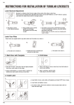
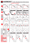
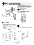
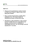
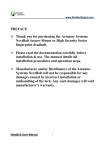
PL3 PL3 KEYPAD ELECTRONIC DEADBOLT INSTALLATION INSTRUCTIONS The BACKSET is the distance between the center of cross bore and edge bore of the door. Adjustable latch fits both BACKSET of 2-3/8” (60mm) and 2-3/4” (70mm). Please follow the steps shown below for BACKSET adjustment. Latch Backset Adjustment : Rotate the latch case as diagram on the right for backset 2-3/4" (70mm) or reverse direction for 2-3/8" (60mm). 1. MARK THE DOOR WITH TEMPLATE ) mm 0 " (7 /4 2-3 2. DRILL HOLES Using the marks as a guide to drill a hole Ø2-1/8” (54mm) through the door face for the lockset, then a hole of Ø1” (25.4mm) for latch. Select the height and backset as desired on the door face ; use the TEMPLATE as an indication to mark the center of the circle on the door face and the center of the door edge. 4. INSTALL STRIKE 3. INSTALL LATCH a. Insert the latch and ensure it is paralleled to the door face. Mark the outline of the faceplate, then take out the latch. a. To identify the center of strike : close the door, on the basis of the faceplate mark horizontal center line of strike. Ensure the center of faceplate and the center of strike are aligned. Use the mark as a guide outlines the strike. b. Chisel 1/8” (3mm) deep along the outline to allow the faceplate to be aligned with the door edge. b. Chisel 5/64” (2mm) deep along the strike outline to allow the strike to be aligned with the doorframe. c. Insert the latch and tighten it with screws. Note : please use tapping screws for metal door. c. Insert the strike and tighten it with screws. Note : please use ”tapping screws” for metal door. 5. Install Keypad Assembly a. Ensure the latch bolt must be retracted. b. Please refer to the diagram below for Cylinder Installation. Place deadbolt against keypad with tailpiece in horizontal position inserted through hub of the latch. c. Pass the IC wire under the latch to the interior side of the door. IC wire Cylinder PL3 PL3 PL3 PL3 6. Install Inside Mounting Plate 9. Install receiver module Pass the IC wire through the wire hole of the mounting plate. Fix the mounting plate with screws. If outside lock assembly is lopsided, please loosen the screws to adjust it's position and tighten the screws again. a. Remove the battery cover (push it up and pull it out). Battery Cover Mounting Plate Screws IC wire 7. Identify Door Handing Face the door from outside, the door is left handed if the hinge is on the left-hand side of the door, whereas the door is right handed if the hinge is on the right-hand side of the door. b. Connect the IC wire and ensure the tailpiece is engaged with turn piece, then attach receiver module to the door with screws. It's optional to use wood screws. (Wood screws only for wood door) Wood Screws Interior Door Hinge (Left Handed) Screws (Right Handed) Exterior 8. Adjusting Turn Piece Turn the turn piece to left for 45 degrees when it's right-handed door. Turn the turn piece to right for 45 degrees when it's left handed door. c. Insert 4 (AA) 1.5V alkaline batteries and put the battery cover back to the receiver module. (Please refer to the User Manual for function setting) Turn Piece (For Right Handed door) (For Left Handed door) TEMPLATE Ø54mm (2-1/8") FOR BACKSET 70mm (2-3/4”) Fit here on door edge FOR BACKSET 60mm (2-3/8”) 51 45 40 35 2" 1-3/4" 1-9/16" 1-3/8" Mark Ø1" (25.4mm) hole at center of door edge. PL3 Lockeyusa P.O. Box 543 Mt. Pleasat, MI 48858 www.lockeyusa.com