1
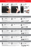
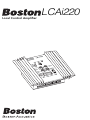
LCAi220
Local Control Amplifier
LCAi220 Important Safety Instructions
This symbol found on the apparatus indicates hazards arising from
dangerous voltages.
This symbol found on the apparatus indicates the user should read all
safety statements found in the user manual.
WARNING! To reduce the risk of fire or electric shock, do not expose this
product to rain or moisture.
1.
Read these instructions.
2.
Keep these instructions.
3.
Heed all warnings.
4.
Follow all instructions.
5.
Do not use this apparatus near water.
6.
Clean only with dry cloth.
7.
Do not block any ventilation openings.Install
in accordance with the manufacturer's
instructions.
8.
Do not install near any heat sources such as
radiators, heat registers, stoves, or other
apparatus (including amplifiers) that produce
heat.
9.
Do not defeat the safety purpose of the
polarized or grounding-type plug. A polarized
plug has two blades with one wider than the
other. A grounding type plug has two blades
and a third grounding prong. The wide blade
or the third prong are provided for your safety.
If the provided plug does not fit into your
outlet, consult an electrician for replacement
of the obsolete outlet.
10. Protect the power cord from being walked on
or pinched particularly at plugs, convenience
receptacles, and the point where they exit
from the apparatus.
11. Unplug this apparatus during lightning storms
or when unused for long periods of time.
12. Refer all servicing to qualified service
personnel. Servicing is required when the
apparatus has been damaged in any way, such
as power-supply cord or plug is damaged,
liquid has been spilled or objects have fallen
into the apparatus, the apparatus has been
exposed to rain or moisture, does not operate
normally, or has been dropped.
13. The power plug at the wall must remain easily
accessible after installation to be able to
disconnect power from the apparatus.
14. Maintain a minimum safe distance of 2 inches
(50mm) around the front of the apparatus for
sufficient ventilation. The ventilation should
not be impeded by placing around the
apparatus items such as newspapers,
tablecloths, curtains, etc.
15. The apparatus shall not be exposed to
dripping or splashing. No objects filled with
liquids, such as vases, shall be placed on the
apparatus.
16. The apparatus is suitable for moderate
climates.
Notice on EMI:
American Users:
Note: This equipment has been tested and found to
comply with the limits for a Class B digital device,
pursuant to part 15 of the FCC Rules. These limits are
designed to provide reasonable protection against
harmful interference in a residential installation. This
equipment generates, uses and can radiate radio
frequency energy and, if not installed and used in
accordance with the instructions, may cause harmful
interference to radio communications. However, there
is no guarantee that interference will not occur in a
particular installation. If this equipment does cause
harmful interference to radio or television reception,
which can be determined by turning the equipment
off and on, the user is encouraged to try to correct the
interference by one or more of the following
measures:
•Reorient or relocate the receiving antenna.
•Increase the separation between the equipment
and receiver.
•Connect the equipment into an outlet on a circuit
different from that to which the receiver is
connected.
•Consult the dealer or an experienced radio/TV
technician for help.
Canadian Users:
This Class B digital apparatus complies with
Canadian ICES-003.
Cet appareil numérique de la classe B est
conforme à la norme NMB-003 du Canada.
1
Local Control amplifier
LCAi220
Thank you
Thank you for selecting a Boston Acoustics LCAi220 Local Control amplifier. Your LCAi220 has
been designed to deliver years of music, enjoyment, and satisfaction. Please keep your manual
in a safe place in case you need to refer to it at a later date. Our Installation Considerations are
a guide for those with and without experience installing a local control amplifier. If at any point
you have questions regarding the connection and installation of this device please contact
technical support at [email protected] or 978.538.5000.
Contents
Thank You ........................................................................................................2
Specifications...................................................................................................2
Introduction .....................................................................................................3
The Technology Inside.................................................................................... 3
Installation Considerations ..............................................................................4
System Diagrams.............................................................................................7
Installation Instructions .................................................................................10
Connection Instructions ................................................................................12
Set Up Instructions ........................................................................................13
TroubleShooting Guide .................................................................................15
Contact Information ......................................................................................16
Specifications
Power
Signal to Noise Ratio
THD at Rated Power
Trigger Voltage - Input
Trigger Voltage - Output
Power Input - LCAi220
Power Input - Power Supply
Input Sensitivity
Dimensions - inside Junction Box
LCAi220
10w x 2 @8Ω / 20w x 2 @4Ω
>95dB
0.04%
3-30 VAC / DC
12 VDC / 200mA
12 - 16 VDC, 2.5A
100 - 240 V~, 50 - 60Hz, 1.8A
500mV @ full output
51⁄8 x 51⁄8 x 21⁄8"
(H x W x D) (not including connections)
131 x 131 x 54mm
2
Introduction
LCAi220
The LCAi220 is an in-wall local zone amplifier that switches between a central audio source
(whole house audio) and a local source (TV, CD player, etc.). In the standby mode, the local
speakers are amplified by a centrally located distribution amplifier. When an input signal is
detected from either the local high level, low level, or the 12v trigger/video in inputs, the
LCAi220 switches on and the speakers switch over to the LCAi220’s high quality amplifier.
The LCAi220 provides a simple, easy to use way to have multi-source audio in any room. Its
compact, in-wall design allows the LCAi220 to fit easily behind a flat panel TV. The LCAi220
mounts in a two-gang wall box with all speaker connections located behind the unit and the
local source inputs and controls located on the front. The end result is an unrivaled
combination of installation ease and performance, and with its auto source switching makes
the LCAi220 literally invisible to the end user.
The Technology Inside
Amplifier
The amplifier used in the Boston Acoustics LCAi220 is a high performance class A/B amplifier
delivering sound quality equivalent to the finest multi-room/multi zone amplifiers or receivers.
Low Voltage Power Requirements:
The LCAi220 features two separate power inputs, one on the front for use with the supplied
power supply and a second located on the rear panel for a centrally mounted power supply.
Since the LCAi220 can operate with 12vdc to 16vdc power, it can be used on the same power
source as many other devices used in home audio installations today allowing an installer to
mount a central power supply and route power to many separate locations.
Local Source High and Low Level Inputs:
The LCAi220 features both high (speaker level) and low level (RCA) inputs allowing for
connection to almost any local audio source.
Adjustable Input Level:
The LCAi has a fully adjustable gain to match the output of the LCAi220 to the central music
source.
Highpass Filter:
The LCAi220 features an adjustable highpass filter for the local speakers. Selectable between
Flat (no crossover engaged), 30Hz @ 12dB, and 100Hz @ 12dB. This is especially useful if using
the LCAi220 with small speakers or with a subwoofer. The highpass is only active when used
with the local zone.
Subwoofer Line Output:
The LCAi220 features a dedicated low-level subwoofer output. The subwoofer output is derived
from both the local source being amplified by the LCAi220 and the whole house system. The
signal from the subwoofer output is a mono signal lowpassed at 85Hz @ 12dB per octave.
Fault Detection / Protection:
The LCAi220 features active circuitry to protect itself against a potentially hazardous situation.
If a fault state is detected, the LCAi220 will go into protection mode and the fault LED will
illuminate.
3
LCAi220 Benefits
•
Level Adjust to match the output of the LCAi220 to the central distribution
audio amplifier
•
Signal Sensing (high and low level) and Input trigger for switching to local
source
•
Output trigger for triggering on a connected component (Subwoofer, Etc.)
•
Great sounding, a perfect system match with Boston Acoustics
speakers
•
Versatility to connect to other manufacturers speakers
•
RCA and High Level Inputs for simple connection to almost any audio source
•
Installs neatly into a common low-voltage dual junction box; Carlon B432A or
equivalent; (32 cu. in.) (2 5⁄8" deep x 4" wide x 4" high)
•
Current sensing for simple switching between central and local audio
•
Easy to install with minimal tools required for hook-up
•
Automatic DC/overload/overdrive protection
Installation Considerations
Choosing Installation / Mounting locations
Convenience, décor, safety requirements, installation ease, and performance are all factors
when considering location choices. Choose locations that work best for the room and its use.
Examples of convenient locations include; behind a wall mounted TV, lower section of a wall,
and near other installed controls. Installation of the audio output wiring should be in accordance with Article 640 of the National Electrical Code® (NEC®) and with local codes and ordinances. Do not install the LCAi220 near any electrical device such as a light switch, dimmer or
other 110 Volt product because of the possibility of induced electrical noise. Mount each
device separately using the prescribed electrical box and other low voltage mounting hardware. Check local code requirements regarding the use of such devices before selecting the
mounting hardware. If you are not sure of the requirements for your area, check with the local
wiring inspector, or with an electrician or custom A/V integrator. Electricians and Custom A/V
integrators are also good choices for installing such devices. If at any time you feel unsure
about wiring, connecting or choosing locations consult with a professional.
Speaker Wiring Requirements
For most applications, it is recommended that you use a minimum of a 16 AWG (American
Wire Gauge) stranded copper wire. Never use a wire gauge smaller than 18 AWG. The higher
the gauge number the thinner the wire is. Heavier wire should be used for longer cable runs.
Wiring should be done in accordance with Article 640 of the National Electrical Code® (NEC®)
and with local codes and ordinances. Class 2 cable (designated CL2, CL2P, or CL2R) is typically
appropriate for use in residential construction. This is a plastic jacketed multi-wire cable. Class
3 cable and other suitable substitute cables may also be used. Table 725.61 of the 2005 NEC
specifies suitable cable substitutions. The use of unjacketed single wires is not permitted. For
commercial or multi-unit residences, other wiring methods and cable types may be required.
If you are not sure of the requirements for your area, check with the local wiring inspector, or
with an electrician or custom A/V integrator. You will require 4 conductors from the amplifier
location to the LCAi220 input, using one 4-conductor or two 2-conductor cables; and 2
conductor cables from the LCAi220 outputs to each speaker location in the room. Electricians
and Custom A/V integrators are good choices for installing such devices. If at any time you feel
unsure about wiring, connecting or choosing locations consult with a professional.
4
Powering the LCAi220
A 16VDC power supply is included for powering the the LCAi220. There are two separate
connection points for powering the LCAi220; a front mounted connection for local powering of
the LCAi220 and a rear mounted connection for central powering of the LCAi220. It is only
necessary that you connect power to one of the connections.
Front Connection
When using the front mounted input, connect the plug from the power supply to the input on
the LCAi220. The power supply plugs into a standard 110VAC outlet.
Rear Connection
When using the rear connection, the power supply is located with the central audio system and
power wire is run from that location to the LCAi220. This configuration will require the use of
the included LCApi power interface. The LCApi allows connection of power wire to the
LCAi220’s included power supply.
Rear Power Wiring Requirements
You will require a 2 conductor cable from the power supply location to the LCAi220 input. The
cable should be at least 18 gauge or heavier and of Class 2 construction or an acceptable
substitute. The installation methods are identical to those for installing the loudspeaker wiring,
although there is no need to increase the wire size beyond 16 gauge. Again, Electricians,
Custom A/V Integrators, and Electrical Inspectors are great resources regarding this subject.
They are also great at installing such devices. If at any time you feel uncomfortable in wiring,
connecting or choosing product locations consult with a professional.
5
New Home Construction Precautions
The wiring and installing of in-wall electronics and devices is easier when the walls are free of
insulation, prior to the drywall being applied. It is important that precautions are taken to
avoid system failures. It is recommended that when wiring your open walls that you are aware
of the potential hazards and the tools and hardware required to avoid them. Nails, screws and
accidentally cut or exposed wire can cause failure in the system. Local hardware stores sell nail
guards that cover the stud where the speaker wire passes through. Using nail guards will
almost guarantee that a nail or a screw won’t damage the speaker wire.
Do not share holes in studs with electrical, alarm or other unrelated low voltage wire. Only drill
the size hole necessary to feed the wire through easily. Secure the speaker wire to the stud as
close to the center of the stud bay as possible using insulated staples or other methods that
won’t damage the jacket of the wire. If using staples be careful not to damage the wire. Be
careful while installing the wire in the walls not to pull, over exert, or radically bend the wire to
a point where damage can occur. Label wires at both ends of the wire and protect those ends
from label damage. Labeling wire is essential and saves significant time during the final hookup of your system. Make sure to leave an appropriate length in each location
making installation easy and neat. DO NOT RUN SPEAKER WIRE PARALLEL WITH THE HOUSE
LIGHT AND POWER CABLES. Locating speaker wire to close to electrical wire and devices can
result in undesired noises such as buzzing, humming and popping noises through the speakers. Locating speaker wire too close to electrical wire and devices can result in undesired noises such as buzzing, humming and popping noises through the speakers. It is OK to cross over
light and power cables if necessary but do so infrequently and only at 90° angles. When at all
possible, keep speaker wire as much as 20-inches (50cm) from light and power cables and a
stud bay away from electrical devices such as switches and outlets. Following these simple precautions will insure that there is no noise from an electrical device.
Retro-fitting an Existing Home
Wiring and installing systems in an existing home can be difficult. If you are unfamiliar with the
tools required to feed wire through existing ceilings and walls it is highly recommended that
you consult an Electrician, Low voltage provider / Installer and /or custom A/V Integrator for
your installation needs. Likewise, if you are unfamiliar with the construction methods of the
home, please consider professional assistance.
Warning
Always turn off the amplifier when connecting volume controls, speakers, or any other
components to the system. Only professionals should perform the installation of these devices
or those possessing skills in construction, experience with the proper use of hand tools,
knowledge of local building and electrical codes, and familiarity with the environment in which
the product(s) will be installed. Install all products to meet all local building, energy and
electrical codes.
Warning About System Impedance
The LCAi220 does not provide impedance matching. If multiple speakers are used, you must
use a volume control and all impedance matching jumpers should be set to the same value.
Not doing so will cause undesirable performance and improper protection for the central
system amplifier.
6
System Diagrams
System 1; Simple Configuration - Front Power Input
In this example, the central music source (receiver located in another part of the house)
provides the default audio for the room. Signal sensing on the RCA connections will trigger the
local source (audio from the TV configured to variable output). Power is connected to the front
input. For additional bass, a powered subwoofer may be used.
12V Trigger /
Video In
TV (local source)
12V Trigger /
Video Pass
Through
LCAi220 (external connections)
16VDC Power Supply
(Included w/LCAi220)
SPEAKER OUT
+ - - +
SPEAKER IN
+ - - +
16VDC
IN
SUB
OUT
+ - + -
LCAi220 (in-wall connections)
Local Speakers
Powered
Subwoofer
(optional)
Central Music Source (Room 2 output)
7
System Diagrams (cont.)
System 2; Simple Configuration - Rear Power Input
This example is similar to the System 1 diagram except the power supply from the LCAi220 is
connected to the rear input with the power routed from a central location (usually located with
the central music source equipment). Also a RVC90i volume control is added for volume
control of the central music source when the LCAi220 is in bypass mode.
12V Trigger /
Video In
TV (local source)
12V Trigger /
Video Pass
Through
LCAi220 (external connections)
SPEAKER OUT
+ - - +
SPEAKER IN
+ - - +
16VDC
IN
SUB
OUT
+ - + -
LCAi220 (in-wall connections)
RVC90i
Volume
Control
LCApi
(Included
w/LCAi220)
Local Speakers
Powered
Subwoofer
(optional)
16VDC
Power Supply
(Included
w/LCAi220)
Central Music Source (Room 2 output)
8
System Diagrams (cont.)
System 3; Complex Configuration - Whole House Audio Diagram
The system below uses six separate zones. Three of the zones use Boston LCAi220 Local
Control Amplifiers powered from a central location. Each Zone uses a Boston RVC90i for
volume control of the local speakers while providing the necessary impedance protection for
the central source amplifier (the Room 2 output of the Boston AVR7120 receiver). The output
from the receiver is sent through a Boston CB8 distribution block out to all six zones.
Zones 1-3: In each zone, the audio signal is sent from the Boston CB8 to a Boston RVC90i
volume control. The Boston RVC90i provides volume control for the local speakers when the
LCAi220 is in bypass mode. Each Boston LCAi220 is connected to a television; this is the local
source for each zone. The local source is triggered via an RCA video output from the TV to the
12v Trigger/Video In located on the front of the Boston LCAi220. Zone 3 adds a subwoofer
system (Boston SA1 subwoofer amplifier and a pair of Boston VRiSub82 subwoofers) for more
bass.
Zones 4-6: Each zone is powered off of the Room 2 output of the AVR7120. The Boston RVC90i
volume controls provide volume control and impedance matching for each specific zone.
Zone 1
Zone 2
12V Trigger /
Video In
TV (local source)
Zone 3
SPEAKER OUT
+ - - +
SPEAKER IN
+ - - +
16VDC
IN
12V Trigger /
Video Pass
Through
12V Trigger /
Video Pass
Through
LCAi220 (external connections)
LCAi220
(in-wall connections)
LCAi220 (external connections)
LCAi220 (external connections)
SUB
OUT
SPEAKER OUT
+ - + -
LCAi220
(in-wall connections)
+ - - +
SPEAKER IN
+ - - +
RVC90i
Volume
Control
16VDC
IN
SUB
OUT
SPEAKER OUT
+ - + -
LCAi220
(in-wall connections)
+ - - +
SPEAKER IN
+ - - +
16VDC
IN
SUB
OUT
+ - + -
RVC90i
Volume
Control
RVC90i
Volume
Control
Local Speakers
Local Speakers
Local Speakers
LCApi
(One included
w/each LCAi220)
16VDC
Power Supply
(One included
w/each LCAi220)
Central Music Source (Room 2 output)
In-Wall Subwoofers
RVC90i
Volume
Control
Zone 4
12V Trigger /
Video In
TV (local source)
12V Trigger /
Video In
TV (local source)
12V Trigger /
Video Pass
Through
RVC90i
Volume
Control
Zone 5
RVC90i
Volume
Control
Zone 6
9
Installation Instructions
Installing / Rear Connections
1. Prewire. Run the speaker wires from the
receiver / amplifier and the power wires
(if applicable) to the junction box and
the speaker wires from the junction box
out to the local speakers. (Figure #1)
Tip: Label the speaker/power wires to simplify connecting the wiring later
Figure #1
Figure #2
2. Install the LCAi220 mounting plate to
the junction box using the two 11⁄4-inch
(32mm) screws. (Figure #2)
3. Strip 1⁄4-inch (7mm) of insulation off of
the end of the wires. Connect the wires
to the removable connector plugs using
a small flathead screwdriver. (Figure #3)
The plugs are labeled and color coded
to simplify installation, the red
connector is for the speaker wires
coming from the amplifier and the black
is for the wires going out to the
speakers.
Figure #3
3a. If using the subwoofer output, connect
the + to the tip of the RCA, connect the
- to the shield of the RCA.
4. Install the connectors to the LCAi220.
(Figure #4)
Figure #4
10
Installing / Rear Connections
(cont.)
Figure #5
5. Install the LCAi220 into the junction
box bottom first. Proceed slowly
making sure not to pinch any of the
wires. (Figure #5)
6. Fasten the LCAi220 to the bracket
using the four 1⁄4-inch (7mm) screws.
(Figure #6)
7. Install the faceplate label to the
LCAi220. (Figure #7)
Figure #6
Figure #7
11
Connection Instructions
Figure #1
Front Connections
1. Connect the local source to either the Left
and Right RCA Inputs (Figure #1) or to the
High Level In speaker level inputs
(Figure #2).
Note: Do not connect wires to both the RCA
and High Level inputs.
Figure #2
2. If used, connect the local source trigger to
the 12V Trigger / Video In (Figure #3).
3. If used, connect the local source trigger
output to the 12V Trigger / Video Pass
Through (Figure #4).
4. If the rear power connection is not used,
connect the power supply input to the
15VDC input (Figure #5).
Figure #3
Note: Only needed if rear power input is not
used.
Front Connection Diagram
Figure #4
A
12V Trigger /
Video In
12V Trigger /
Video Pass
Through
C
B
D
E
A A.
B
B.
15VDC Power Input
C.
12V Trigger / Video In
C D.
E.
12
Left and Right RCA Inputs
D
12V Trigger / Video Pass Through
12V Trigger /
Video In
Left and Right High Level Inputs
12V Trigger /
Video Pass
Through
E
F
Figure #5
Set Up Instructions
Central Music System
Configuration
Adjust the levels for the central music
system. If an in-wall volume control is
used, follow its instructions for
configuration before continuing.
If a volume control is not used, start with
the volume on the central music system
low, and turn it up until a comfortable
volume level is achieved.
Adjusting the Highpass (HP)
Filter on the LCAi220
HP - Flat
The LCAi220 features a selectable
highpass filter to remove low frequency
information from the local speakers
when amplified by the LCAi220. This is
especially useful when using smaller
speakers or when use in conjunction
with a powered subwoofer.
Flat:
No filter engaged, larger
speakers
30Hz:
Larger speakers with a
powered subwoofer or
smaller speakers without
a powered subwoofer
100Hz: Smaller speakers with or
without a powered
subwoofer
HP - 30Hz
HP - 100Hz
Note: If at higher volumes the sound
becomes distorted, especially during
heavier bass passages, it may be
necessary to increase the highpass
setting to a higher value.
13
Adjusting the Input
Once the audio level from the central music
system is configured:
Figure #1
1. Disconnect / turn off the power source to the
LCAi220.
2. Set the device used for the local source to
variable output.
3. Turn the input level on the LCAi220 to minimum,
all of the way counter-clockwise. (Figure #1)
4. Reconnect / turn on the power source of the
LCAi220.
Figure #2
5. Turn on the local source device. Adjust the
volume on the source device to approximately
80% of total output. Slowly turn up (clockwise)
the input level control on the LCAi220. (Figure
#2) The local LED will illuminate once a source is
detected. Continue to turn up the desired maxiA level is achieved.
mum
12V Trigger /
Video In
6. If a subwoofer is connected to the LCAi220,
C
adjust the subwoofer gain so it is balanced with
theBmain speakers.
D
12V Trigger /
Video Pass
Through
E
Front Controls Diagram
A
B
D
C
12V Trigger /
Video In
12V Trigger /
Video Pass
Through
14
A.
Local source LED
B.
Power LED
C.
Selectable highpass for local
speakers
D.
Fault LED
E.
Input level adjustment
F.
F5A Fuse
E
F
TroubleShooting Guide
Problem
Cause
Solution
No Power
• Local power supply is off or
disconnected
• Central power supply is off or
disconnected
• Check / connect local power
supply
• Check / connect central power
supply and rear connection to
LCAi220
No Sound
• Speaker wires are disconnected
• Volume is adjusted too low
• Source is off / disconnected
• Connect speaker wires
• Adjust source volume
• Check source connections and
power status
No Audio From Local
Zone
• Source not configured correctly
• Connections to LCAi220 are not
made correctly
• Check local source
• Check all connections.
No Audio in Bypass Mode
• Central music system is not on /
configured correctly
• Connections to LCAi220 are not
made correctly
• Configure central audio system
• Check all connections
Fault Light is On
• DC detected at speaker leads
• Check all wiring and
connections
Fault Light Flashes Once
Per Second
• Short circuit detected at speaker leads
• Check all wiring and
connections
• Make Sure load to the amplifier is 4Ω or
higher
Fault Light Flashes Once
Every Two Seconds
• Thermal - the amplifier has overheated.
• Check all wiring and
connections
• Make Sure load to the amplifier is 4Ω or
higher
Local zone;
distortion at higher
volumes
• Gain on the LCAi220 is too high,
volume is up to high on the
local source
• Lower gains / volume levels on
the LCAi220 and local source
Warning: Always disconnect power to the LCAi220 and shut down any connected devices before
making/checking any front or rear connections on the LCAi220.
15
If Service Seems Necessary
First, contact the dealer from whom you purchased the LCAi220. If that is not possible, write
to:
Boston Acoustics, Inc.
Attn: Parts and Service
300 Jubilee Drive
Peabody, MA 01960 U.S.A.
Or contact us via e-mail at:
[email protected]
We will promptly advise you of what action to take. If it is necessary to return your LCAi220 to
the factory, please ship it prepaid. After it has been repaired, we will return it freight prepaid in
the U.S.A. and Canada.
16
17
300 Jubilee Drive
Peabody, MA 01960
U.S.A.
978.538.5000
www.bostonacoustics.com
Boston, Boston Acoustics, and the Boston Acoustics logo are
registered trademarks of Boston Acoustics, Inc.
Specifications are subject to change without notice.
© 2005 Boston Acoustics, Inc.
042-002262-1