1
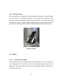
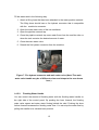
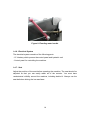
ICECAT GAS/PRO220 ICE RESURFACER
USER AND MAINTENANCE MANUAL
FROM SERIAL# 120
TABLE OF CONTENTS
1.
USER MANUAL ............................................................................................4
1.1.
Introduction ..............................................................................................................4
1.2.
Safety Instructions ...................................................................................................4
1.3.
Machine Dimensions ................................................................................................5
1.4.
Main Parts of the Machine........................................................................................6
1.4.1.
Controls ............................................................................................................7
1.4.2.
Driving Controls ...............................................................................................8
1.4.3.
Meters ...............................................................................................................8
Operating Hour Meter ..................................................................................8
1.4.3.2.
Oil Window ...................................................................................................9
1.4.3.3.
Dirt Indicator ................................................................................................9
1.4.4.
Control Panel..................................................................................................10
1.4.5.
Water System .................................................................................................12
1.4.5.1.
Filling the Water Tanks ..............................................................................12
1.4.5.2.
Flooding Water Handle ..............................................................................13
1.4.6.
Electrical System............................................................................................14
1.4.7.
Seat .................................................................................................................14
1.5.
2.
1.4.3.1.
Using the Machine ..................................................................................................15
1.5.1.
Starting ...........................................................................................................15
1.5.2.
Moving ............................................................................................................15
1.5.3.
Reversing .......................................................................................................15
1.5.4.
Ice Maintenance .............................................................................................17
1.5.4.1.
Side Brush..................................................................................................17
1.5.4.2.
Sled.............................................................................................................17
1.5.4.3.
Auger ..........................................................................................................17
1.5.4.4.
Water Spreading Towel..............................................................................17
1.5.4.5.
Flooding Water...........................................................................................18
1.5.4.6.
Emptying the Snow Tank ...........................................................................18
1.5.5.
Storage ...........................................................................................................18
1.5.6.
Towing ............................................................................................................18
MAINTENANCE ..........................................................................................21
2.1.
Blade .......................................................................................................................21
2.2.
Hydraulics ...............................................................................................................22
2
2.2.1.
Oils..................................................................................................................22
2.2.2.
Filters..............................................................................................................23
2.2.3.
Hoses ..............................................................................................................23
2.2.4.
Valves .............................................................................................................24
2.2.5.
Pumps.............................................................................................................24
2.2.6.
Hub Motors .....................................................................................................24
2.2.7.
Cylinders ........................................................................................................24
2.3.
Mechanics ...............................................................................................................24
2.3.1.
Motor...............................................................................................................24
2.3.2.
Bearings .........................................................................................................25
2.3.3.
Screws and Nuts ............................................................................................26
2.3.4.
Belts and Chain ..............................................................................................26
2.3.5.
Gas Springs ....................................................................................................26
2.4.
Water System..........................................................................................................26
2.5.
Electrical System ....................................................................................................26
2.5.1.
Fuses ..............................................................................................................27
2.5.2.
Lights ..............................................................................................................30
2.5.3.
Painted Body Parts ........................................................................................30
2.5.4.
Stainless Steel Parts ......................................................................................30
2.5.5.
Plastic Parts ...................................................................................................30
2.5.6.
Aluminium Parts.............................................................................................30
2.6.
Disposal ..................................................................................................................30
3
1. USER MANUAL
1.1. Introduction
Use of the ICECAT GAS/PRO220 ice resurfacer requires basic knowledge of the
use and operation of the machine. Stancon Oy organises basic training for
operators of the machine.
The purpose of this manual is to familiarise the reader with the structure, use and
maintenance of the machine. This manual assumes that the reader is familiar
with the basics of ice maintenance and operation of ice resurfacers.
Please read this manual carefully before operating the ice resurfacer.
1.2. Safety Instructions
- Familiarise yourself carefully with the machine’s controls and monitoring
equipment
- To prevent leaks, close all gas bottles or gasoline tanks for the night
- Before using the machine, ensure that all meters, alarm LEDs and other
controls are in normal operating condition
- Do not hesitate to stop the machine to prevent an accident or damage
- Pay special attention and take care when using the ice resurfacer since, as
the operator, you have the primary responsibility for the machine’s effective
and safe operation
- Although the ice resurfacer is designed to be as easy to use and safe as
possible, just one mistake by the operator or neglecting a single safety issue
can cause an accident or damage the machine
- Before using the machine, ensure that all protective covers are in place
- When the machine is in use, only authorised ice maintenance personnel
may remain on the ice
- Be very careful when handling the shaving blade
- Drive carefully
4
- If you need to tow the ice resurfacer, refer to section 1.5.7. Towing for
instructions
1.3. Machine Dimensions
Length
3,950 mm
Width:
2,350 mm
Height:
2,100 mm
Working width:
2,200 mm
Axle width:
1,950 mm
Wheel track:
1,600 mm
Turning radius:
3,800 mm
Length with the snow tank up:
4,600 mm
Height with the snow tank up:
3,500 mm
Floor height of the operator’s compartment:
1,185 mm
Operator’s seat, height from the floor:
1,600 mm
Weight, empty:
2,490 kg
Weight, water tank full:
3,190 kg
Tyres:
225/70 R 15C, 112/110W
Tyre pressure:
65 psi (4,5 bar)
Volume of snow tank:
approx. 3,3 m3
Volume of flooding water tank:
700 l
Volume of hydraulic oil tank:
60 l
5
1.4. Main Parts of the Machine
The ice resurfacer consists of three main parts. The front frame contains the
snow tank, batteries, and the hydraulic unit. The back frame contains the auger,
the flooding water tank, and the operator’s compartment, and is jointed to the
front frame. The joint enables driving on uneven surfaces – e.g., when emptying
the snow tank outside. The back frame is attached with a sled, which is primarily
used for the ice maintenance. The sled contains the shaving blade, which must
be handled with extreme care.
Figure 1. ICECAT GAS/PRO220 Ice Resurfacer
6
1.4.1. Controls
To ensure easy use during ice maintenance, the ice resurfacer’s controls are
located close to the operator.
Figure 2. Operator’s compartment
7
1.4.2. Driving Controls
The ice resurfacer is steered with a steering wheel, which turns the front wheels
of the machine to the desired direction. You can select the direction of the
machine (forward or backward) with the direction selector, and control the speed
by means of a pedal. To apply brakes, reduce pressure on the pedal or remove
your foot from it; the hydraulic system will then apply the brakes automatically.
Figure 3. Pedal
1.4.3. Meters
1.4.3.1.
Operating Hour Meter
The operating hour meter indicates the total operating hours of the machine in
hours. Operating hours can be read from the Murphy-display located in the
dashboard. The meter starts running once the electrical system is turned on by
turning the ignition key.
8
1.4.3.2.
Oil Window
You can check the oil level in the oil tank from the oil window on the side of the
hydraulic oil tank. When the machine is on an even surface, the oil surface level
should be visible in the window. The system contains a total of 60 litres of
hydraulic oil.
1.4.3.3.
Dirt Indicator
The dirt indicator on the return oil filter indicates how dirty the filter is. Once the
indicator reaches the red area, the filter must be replaced immediately, even if
the normal change interval has not yet passed.
Figure 4. Oil window and return oil filter dirt indicator
9
1.4.4. Control Panel
Buttons for starting the various functions of the machine are located close to the
operator on the control panel. To avoid any unexpected functions being engaged
during start-up, check the positions of the buttons before starting the machine.
Figure 5. Control panel
10
1. The ignition key switch has three positions. When the key is vertical, the
main current of the machine is switched off. When the key is turned to the
right from its vertical position, the main current is switched on. Turning the
key to the extreme right starts up the motor.
2. RPM Selector. Use to change between idle speed and working speed
RPM’s.
3. SNOW TANK: You can open the snow tank cover and lift up the tank’s
tipping device by pressing the snow tank button upwards.
4. PARK BRAKE: Use this button to switch on the parking brake. For safety
reasons, brakes are applied when the rotational speed of the motor is less
than 1,000 rpm, even if the parking brake is not on.
5. SEAT HEATER: Heater for the operator’s seat.
6. LIGHTS: Turn on the headlights to improve visibility and safety if you are
using the machine in an area where there may be other people.
7. HORN.
8. AUGER: To start the auger, press the button down. To remove snow and
ice that has lodged in the auger apparatus, press the button up.
9. SLED: Press this button to raise and lower the sled.
10. TOWEL: Press this button to raise and lower the towel that spreads water.
11. BREAKER: This switches on the auger breaker, which stops the auger
from blocking. The breaker can only be switched on when the auger is on.
12. SIDE BRUSH: Press the button down to start rotating the brush and
moving it to the working position. Press the button up to raise the brush
from the ice.
13. Direction selector. Use this button to select the driving direction: forward or
backward. The button must remain in the central (neutral) position when
the power is on but you do not intend to move the machine. When backing
up, you should hear the back-up signal.
11
Figure 6. RPM selector (above) and Direction selector (below)
1.4.5. Water System
The ice resurfacer’s water system consists of the following parts: The water tank
is filled via the main water valve and the filling pipes, and the flooding water flows
behind the sled from the tank under its own pressure. You can adjust the amount
of water by using the flooding water lever. The towel is used to spread the water
onto the ice to form an even surface.
1.4.5.1.
Filling the Water Tanks
The ice resurfacer has a fire hydrant connector and a main water valve under the
operator’s seat for filling the water tanks.
The water must be cooler than 80 °C. If the water is too hot, it can soften the
hoses, which can inhibit water flow.
12
Fill the water tank in the following way:
1. Attach a filling hose that has been attached to the water pipeline network:
The filling hose should have a fire hydrant connector that is compatible
with the machine’s connector.
2. Open the main water valve of the ice resurfacer.
3. Open the pipeline network tap.
4. Close the pipeline network tap once water flows from the overflow tube or
when the tank contains the desired amount of water.
5. Close the main water valve.
6. Detach the fire hydrant connector from the machine.
Figure 7. Fire hydrant connector and main water valve (Note! The main
water valve handle may be of different colour and shape to the one shown
here.)
1.4.5.2.
Flooding Water Handle
You can control the amount of flooding water with the flooding water handle on
the right side of the control panel. By pushing the lever forward, the flooding
water valve opens and water starts flowing behind the sled. Pushing the lever
further forward increases the flooding water flow. You can stop the water flow by
pulling the handle to its extreme back position.
13
Figure 8. Flooding water handle
1.4.6. Electrical System
The electrical system consists of the following parts:
- 12 V battery which powers the control panel and hydraulic unit
- Control panel for controlling the machine.
1.4.7. Seat
Adjust the position of the seat before operating the machine. The seat should be
adjusted so that you can easily reach all of the controls. You must have
unobstructed visibility around the machine, including behind it. Always use the
seat belt when driving the ice resurfacer.
14
1.5. Using the Machine
1.5.1. Starting
Start the machine according to the following instructions:
- Open either gasoline tap in the gasoline tank (GAS220 machines) or LPG
bottles (PRO220 machines) depending which machine you have.
- Check that the ignition key has been turned to its extreme left position, the
direction selector is in its middle (neutral) position, the motor rotation speed is
low, and all buttons are in their upper or middle positions (indicating that the
functions controlled by them are off).
- Turn the ignition key to the right; i.e. from the vertical position to the current-on
position.
- Turn the key to the start-up (extreme right) position to start the motor.
- Let the motor run for 30 seconds before starting work.
1.5.2. Moving
To move the ice resurfacer, select a driving direction with the direction selector
and depress the pedal. The more pressure you apply on the pedal, the quicker
the machine moves. Before moving the machine, fasten your seat belt. While
driving the machine, keep in mind that the grip of the studded tyres on both wet
and dry ice is limited and that driving too quickly can result in uncontrolled
movement of the machine. The machine must not be driven on sloping surfaces
or steep hills.
1.5.3. Reversing
To back up, select the backward direction with the driving direction selector. You
will hear the back-up signal and the machine will back up. When backing up,
15
control the speed of the machine with the pedal. Please note that the ice
resurfacer goes backwards as quickly as it does forwards.
16
1.5.4. Ice Maintenance
The following sections describe the tasks and functions associated with ice
maintenance.
1.5.4.1.
Side Brush
The side brush is used for maintaining the sides of an ice rink. The brush
removes snow and ice flakes from the side areas that cannot be reached by the
sled. When the side brush is used, the doors of the ice rink must be closed to
avoid damaging the brush on door jams or other obstacles.
1.5.4.2.
Sled
The sled is lowered to the ice and kept pressed down during ice maintenance.
Hydraulic cylinders press the sled against the ice and ensure that shaving results
are even. Lift the sled when you leave the ice so that neither the shaving blade
nor the auger comes in contact with any obstacles.
1.5.4.3.
Auger
The auger moves the snow and ice flakes created by skaters into the snow tank.
When necessary, you can stop the auger during operation, in which case the
snow is gathered in the sled. You can run the auger in the opposite direction to
remove possible blockages.
1.5.4.4.
Water Spreading Towel
The water-spreading towel spreads flooding water evenly onto the ice. The towel
is lowered and lifted hydraulically. Dampen the towel before ice maintenance: a
dry towel does not spread water evenly, and parts of the dry towel may remain
above the ice surface, resulting in streaks on the ice.
17
1.5.4.5.
Flooding Water
Flooding water finishes the shaved ice surface. You can change the thickness of
the ice by adjusting the amount of water and the shaving depth. Excessive use of
flooding water results in flooding, whereas too little flooding water results in dry
and uneven streaks.
1.5.4.6.
Emptying the Snow Tank
Before emptying the snow tank, ensure that the snow can fall freely from the
opening tank and that no one will be in the path of the falling snow. To empty the
snow tank, press the button until the snow tank cover and the tipping cylinder are
lifted to their extreme upright position and the movement of the tank stops. If any
snow remains in the snow tank, lower the tank slightly by pressing the button
down and then lift the tank back to its upright position. In addition to emptying the
snow tank, you can remove snow from the auger by running the auger in the
opposite direction.
1.5.5. Storage
The ice resurfacer should be stored at a room temperature of above 20 °C, at
normal humidity levels. When the ice resurfacer is not in use, switch off the
power and close the gas bottles. The snow tank must be lifted up so that the tank
can dry and air can circulate freely under it. Use the maintenance support to
ensure that the snow tank remains up. Service all parts of the machine, and
grease all of the joints. In addition, protect the machine from humidity and store it
in sufficiently warm conditions (see above).
1.5.6. Towing
If the machine needs to be towed, for maintenance or other reasons, do the
following:
Close the brake release lever on the front side of the flooding water tank (picture
9).
18
Figure 9. Brake release lever
Release the brakes by turning the hand pump valve (1) left.
Figure 10. Hand pump
Pump the hand pump to release the brakes (at least 10 times). Close the hand
pump valve (1) by turning it to the extreme right (as shown in the figure).
Switch wheel motors to neutral.
19
Figure 11. Wheel release valve in open and closed position
Lift the sled with the hand pump by turning the hand pump valve right and the
snow tank and sled lifting valve to the “SLED” position.
Figure 12. Snow tank and sled lifting valve in “closed” position
Prepare to switch off the machine before towing starts.
20
2. MAINTENANCE
All parts of the ice resurfacer must operate flawlessly in order for the machine to
function properly. We recommend that the operator monitors the condition of the
parts and carries out all necessary maintenance procedures as soon as possible,
to avoid damage. The machine should be serviced twice a year. Maintenance
tasks for various parts and parts that require special attention are listed below.
2.1. Blade
Monitor the condition of the blade continuously. If the blade is damaged or blunt,
the shaving result will be noticeably different from that of a sharp blade. The
quality of the ice affects the durability of the blade. Once you become more
experienced in the use of the machine, you will be able to recognise when the
blade is blunt and determine when it must be replaced.
Be extremely careful when handling the blade!
Change the blade according to the following instructions:
- Place the sled on supports
- Place boards or other supports under the blade
- Remove the cover sheets from the top of the sled
- Open the screws that attach the blade, starting from the sides and moving
toward the centre
- Let the blade fall onto the boards
- Pull the old blade from under the sled
- Lift the old blade into a blade cover and secure the mounting nuts
- Mark the blunt blade
- Remove the new blade from its blade cover
- Lift the new blade onto the boards
- Push the new blade under the sled
- Lift the blade from one end and partially tighten the mounting screw
21
- Lift the other end of the blade and tighten as above
- Attach the rest of the screws, but don’t tighten them yet
- Begin tightening from the centre screw, moving toward the side; finish one side
before starting the other
- Tighten the screws on the other side as above, moving from the centre toward
the side
- Place the cover sheets back on the sled
- Lift the sled and then remove the boards from under the sled
- Adjust the blade in a horizontal position by turning the adjustment screws so
that the blade’s entire length shaves the ice
2.2. Hydraulics
Keep the hydraulic system clean, and watch out for possible leaks. Monitor the
oil temperature to detect possible faults in the hydraulic components and to avoid
faults that prevent use of the machine.
2.2.1. Oils
Check the oil level daily. After use, take note of the oil temperature. For a new
machine, the oil must be changed when the operating hour meter reaches 100
hours. The next oil change is carried out when the operating time reaches 500
hours. Thereafter, the oil should be changed following every 500 hours of
operation. If the machine is not used for an extended period of time, check the oil
quality and, if necessary, change the oil. Fill the oil tank through the cap in the
return oil filter to avoid introducing any impurities to the system.
22
Figure 13. Fill the oil tank through the return oil filter cap
2.2.2. Filters
The oil tank contains two filters. The high-pressure filter is located behind the
tank and the return oil filter in the right front corner of the tank. Change the filters
after every 500 hours of operation. The return oil filter must be changed sooner
than that if the filter’s indicator reaches the red area.
Figure 14. Return oil filter on the left, high-pressure filter on the right
2.2.3. Hoses
Keep the hoses clean, and monitor the tightness of hose joints. Check the hoses
for possible wear and tear, and replace any damaged hoses.
23
2.2.4. Valves
Check the operation of the hydraulic unit valves daily by using all of the
machine’s functions. Check that oil does not leak from the valves, and keep the
valves clean. Qualified ICECAT service personnel will take care of valve
adjustments for you.
2.2.5. Pumps
Monitor the temperature and sounds of the pumps. Should you hear unusual
sounds from the pumps, or should they overheat, contact ICECAT service
personnel.
2.2.6. Hub Motors
Check the operation of the parking brake daily.
2.2.7. Cylinders
Check the operation of the cylinders daily. Pay special attention to the condition
of the cylinder shanks. Any oil leaks at the base of the shank indicate broken
seals. When storing the machine for an extended period of time, make sure that
the cylinder shanks are placed inside the cylinders.
2.3. Mechanics
2.3.1. Motor
Maintain the motor according to the manufacturer’s instructions – see below. The
motor’s maintenance manual is attached to this user manual.
24
2.3.2. Bearings
Grease bearings with grease nipples once a week, especially the vertical auger
bearings. Check and grease tie rod ends once a week. Check the condition of
slide bearings once a week, and lubricate the sled’s brass bearings and
adjustment screws every week. The condition and operation of all bearings must
be checked during service work.
25
2.3.3. Screws and Nuts
Check the tightness of screws and nuts before every use, and check the bolts of
the aluminium wheels every day.
Keep the blade adjustment screws lubricated.
2.3.4. Belts and Chain
Check the tightness and condition of the belts and the chain every week.
Replace any worn parts immediately.
2.3.5. Gas Springs
The blade block is pressed against the ice with gas springs. A wavy shaving
result indicates that a gas spring is damaged. Replace the gas springs when
necessary.
2.4. Water System
Lime and other impurities must be cleaned from the immersion pump, tanks and
hoses during every servicing. Monitor the condition of the water hoses and the
water flow speed. Any anomalies in the water system must be fixed immediately.
Open and clean the water valves once a month. Replace the water spreading
towel immediately if it is broken or starts to fray.
2.5. Electrical System
All electrical equipment is limited splash waterproof. Should water be spilled onto
the electrical equipment, dry it immediately. When in doubt, please contact
Stancon Oy.
26
2.5.1. Fuses
In the event of an electrical fault, check the fuses first and replace any that have
blown. The machine uses ATO fuses.
Fuses can be found behind rear cover. Remove cover and open also the cover of
the Electric unit.
Main
fuse 30A
Power relay
Relays
Fuses
Figure 15. Electric unit (cover removed)
27
F1
F16
- Fuses from left to right:
1. Augers
10 A
2. Snow tank
15 A
3. Conditioner
10 A
4. Water-spreading towel
10 A
5. Side brush
10 A
6. Hydraulics
20 A
7. MIL malfunction indicator 10 A
8. High RPM
5A
9. Free rotation
10 A
10. Lights
10 A
11. Seat heater
10 A
12. Ignition
15 A
13. Snow tank light
10 A
14. Spare
-
15. Hydac Controller
10 A
16. Hydac Valves
2 A
Main fuse 30A is separately on top of the Electric unit. See Figure 15.
28
1
2
3
4
5
- Motor fuses, from left to right:
1. Snow breaker (timer)
2. Augers forward
3. Augers reverse
4. Snow tank down
5. Snow tank up
6. Conditioner up
7. Conditioner down
8. Lights
29
6
7
8
2.5.2. Lights
Check the headlight alignment during service work and replace any blown bulbs
immediately. Keep the headlights clean.
2.5.3. Painted Body Parts
To prevent rusting, repaint any breaks in the paint surface immediately.
2.5.4. Stainless Steel Parts
Keep the unpainted surfaces clean to prevent corrosion. If you detect rust on the
stainless steel surfaces, remove it immediately with a suitable cleaner or with
sand paper.
2.5.5. Plastic Parts
Monitor the condition of the plastic parts during use. Small defects and cracks
can be repaired; damaged parts must be replaced immediately.
2.5.6. Aluminium Parts
Keep the control panel surface and the floor of the operator’s compartment clean.
Do not break the anodised surface by rubbing. Handle the aluminium wheels with
care.
2.6. Disposal
With proper use and maintenance, the ice resurfacer will serve you for a long
time. When the machine becomes too old and maintenance is no longer viable,
dispose of the machine in an appropriate manner. You can deliver the machine
to an official machine recycling facility, where the parts can be dismantled
appropriately.
30