1
July, 2010
USER MANUAL
for
M3P SCoPE Plug-in:
XML Management for DSE
Version 1.0.5
Copyright © 2008-2010 University of Cantabria (UC)
Copyright Notice
Copyright (c) 2008-2010 by the University of Cantabria. All Rights reserved.
This software and documentation are furnished under both GPL and LGPL licenses. The software
and documentation may be used or copied only in accordance with the terms of the license
agreement. You can access the GNU web site for more details on the licenses.
Right to Copy Documentation
The license agreement permits licensee to make copies of the documentation.
Each copy shall include all copyrights, trademarks, service marks, and proprietary rights notices, if
any.
Disclaimer
THE CONTRIBUTORS AND THEIR LICENSORS MAKE NO WARRANTY
OF ANY KIND WITH REGARD TO THIS MATERIAL, INCLUDING, BUT
NOT LIMITED TO, THE IMPLIED WARRANTIES OF
MERCHANTABILITY AND FITNESS FOR A PARTICULAR PURPOSE.
Bugs and Suggestions
Please report bugs and suggestions about this document to
http://www.teisa.unican.es/scope
Copyright © 2008-2010 University of Cantabria (UC)
Contributors
The XML plug-in for SCoPE was created by the following individuals:
Héctor Posadas, University of Cantabria
Gerardo de Miguel, University of Cantabria
Sara Real, University of Cantabria
This document was authorized by:
Eugenio Villar, University of Cantabria
Copyright © 2008-2010 University of Cantabria (UC)
Contents
1.- OVERVIEW....................................................................................................................................5
1.1 Use for Design Space Exploration: Multicube Project..............................................................6
2.- BACKGROUND: ..........................................................................................................................8
2.1 SCoPE........................................................................................................................................8
2.1.1 Software Estimation & Modeling......................................................................................8
2.1.2 Hardware platform simulation...........................................................................................9
2.1.3 System simulation..............................................................................................................9
3.- INSTALLATION AND USE........................................................................................................10
3.1 Installation requirements..........................................................................................................10
3.2 Installation steps......................................................................................................................10
3.2.1 Environment variables.....................................................................................................10
3.3 Usage of M3-SCoPE................................................................................................................11
3.3.1 Using M3-SCoPE as a tool...............................................................................................11
3.3.2 Using M3P and SCoPE as C++ libraries..........................................................................12
3.3.3 Using M3P and SCoPE with SystemC platform descriptions..........................................12
3.4 Using the XML interface.........................................................................................................13
3.5 Command line options.............................................................................................................13
4.- SYSTEM DESCRIPTION............................................................................................................15
4.1 XML System Description file..................................................................................................15
4.1.1 General file structure........................................................................................................15
4.1.2 HW Platform....................................................................................................................16
4.1.3 SW Platform.....................................................................................................................19
4.1.4 Application SW................................................................................................................21
4.1.5 Simulation parameters......................................................................................................23
4.1.6 Additional Rules...............................................................................................................24
5.- SYSTEM CONFIGURATION......................................................................................................26
5.1 XML System Configuration file..............................................................................................26
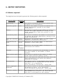
6.- METRIC REPORTING................................................................................................................27
6.1 Metrics reported.......................................................................................................................27
6.2 XML Metric Definition file.....................................................................................................28
6.3 XML Metric Report file...........................................................................................................28
7.- ADDITIONAL FEAUTRES.........................................................................................................29
7.1 Using the ARP library..............................................................................................................29
7.1.1 Compilation for ARP-SCoPE integration........................................................................29
7.1.2 Using ARP-SCoPE in a simulation..................................................................................29
8.- EXAMPLES..................................................................................................................................30
8.1 Hello World..............................................................................................................................30
8.2 Hello World Parameterized......................................................................................................34
8.3 Variable example......................................................................................................................35
8.4 Vocoder....................................................................................................................................35
9.- Glossary.........................................................................................................................................41
Copyright © 2008-2010 University of Cantabria (UC)
1.- OVERVIEW
SCoPE is a SystemC extension for system modeling based on approximately (loosely) timed
descriptions of the system components. As a SystemC extension library, SCoPE has been designed
to receive the system descriptions as SystemC code. However, in order to minimize the designer
effort, a easier interface for describing the systems is required.
This plug-in has been prepared to accept the system descriptions in a friendly format (XML) and
automatically generate the system model. The use of the plug-in hides SCoPE and even SystemC to
the user. Thus, the user does not require specific knowledge about SCoPE. Just by providing the
system description in XML and the code of the SW tasks, the simulator creates the system model.
Only in case the user wants to add specific HW components direct interaction with SCoPE is
required.
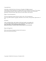
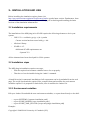
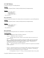
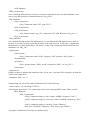
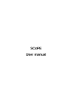
The plug-in has been developed to simplify the interaction mechanisms between the modeling
engine and the user or other tools, without loosing flexibility. Three input XML files have been and
an XML output files have bee defined for this purpose (figure 1).
The three input files are the following: a file describing the entire system, except for punctual
parameters, a file fixing these parameters, and file defining the metrics the simulation have to
report. Component instantiations and connections are created automatically following the XML
files. The System Description file is mandatory to use the M3Plugin. The System Configuration and
the Metric Definition files are optional. The System Configuration file is required if the System
Description file contain unresolved parameters. The Metric Definition file is required if the user
expects the tool will report any metric in the XML output file. This can be useful it the user only
needs to perform a timed system simulation or if the standard SCoPE reports provided in the shell at
the end of the simulation are enough.
XML
System
Configuration
XML
System
Description
XML
Metric
Definition
M3Plugin
SW code
SCoPE
Specific HW
components
SystemC
XML
System
Metrics
Figure 1: M3P inputs and output diagram
The plug-in generates an output file, called System Metrics, when the simulation finishes. This file
Copyright © 2008-2010 University of Cantabria (UC)
contain the values of the metrics defined in the input Metric Definition file. These values are the
result of the previous simulation. If no metrics file is provided, the output metrics file is empty.
The plug-in contains the sc_main function. The user does not require creating it. The plug-in creates
the sc_main function with all the required functionality to create the system model from the XML
files, execute the simulation and return the required metrics at the end of the simulation.
To create the simulator, the user has to compile the SW code using the SCoPE compiler. Then, the
compiled code has to be linked with the SystemC library, the SCoPE library and the M3P library.
This operation creates a simulation executable. Thus, the simulation can be run, by providing the
name of the XML files as argument, as shown in section 3.
1.1 Use for Design Space Exploration: Multicube Project
The plug-in has been specially designed to interconnect SCoPE and a Design Space Exploration
tool. The simplified and flexible XML interface together with the fast and accurate modeling
capabilities of SCoPE makes this simulator really adequate to be user in a DSE design flow.
To use the M3P plug-in together with the SCoPE library in a DSE environment, the user has to
create the use case simulator (figure 1). This includes SCoPE and the M3P plug-in, a XML system
description file (see section 4) and all the system components: SW code and HW peripheral models.
If the XML system description file has not unfixed parameters, nothing more is required to simulate
the system.
However, this solution is not feasible for DSE. DSE requires performing several simulations
modifying certain system parameters without recompiling. In that case, the XML System
Description is expected to have unresolved all these parameters that can be modified. Thus, a XML
System Configuration file with the values of these parameters is required. With that solution only
modifying the XML System Configuration file multiple simulations can be performed without
recompiling the use case simulation.
Furthermore, the XML Design Space file can inform both the DSE tool and the simulator about the
metrics that are required to perform the exploration and decide the best configuration possible.
The tool infrastructure proposed has been defined in the European Multicube project. The
MULTICUBE project focuses on the definition of an automatic multi-objective Design Space
Exploration (DSE) framework to be used to tune the System-on-Chip architecture for the target
application evaluating a set of metrics (e.g. energy, latency, throughput, bandwidth, QoS, etc.) for
the next generation embedded multimedia platforms.
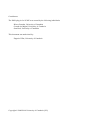
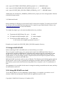
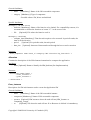
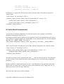
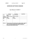
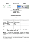
Figure 2 presents an example of a HW/SW system exploration using SCoPE and this plug-in. The
System simulation (called “Use case simulator”) requires to be created:
– The models of the SW and Specific-HW components of the system.
– The XML System Description, containing how the system architecture, how the system
components are connected and the required information to start the SW tasks.
– SCoPE and the M3P plug-in
Copyright © 2008-2010 University of Cantabria (UC)
Figure 2: Using SCoPE and M3P as simulator for DSE
In that figure, to explore the best configuration for the HW/SW system, the XML Design Space file
is also required. From the information of this file, the DSE tool generate multiple configurations
and launch the corresponding simulator executions in order to obtain the performance results of
each configuration. Them the DSE tool can decide which one is the best one analyzing the metrics
reported by the simulator.
The specifications of the XML Design Space, XML System Configuration and XML System
Metrics files have been defined in the Multicube Project. These specifications represents a standard
way to create intermediate files. These files allows easy tool interconnection
The information required in the XML System Metrics file about which system metrics have to be
reported at the end of the simulation can be provided as an specific file. Furthermore, as this
information is usually part of the XML Design Space File it is also possible to reuse this file as an
input to the use case simulator (See the dotted line in figure 2).
This plug-in has been created as part of the European Multicube project. For more information you
can visit www.multicube.eu
Copyright © 2008-2010 University of Cantabria (UC)
2.- BACKGROUND:
2.1 SCoPE
SCoPE tool provides the technology to perform MPSoC HW/SW co-simulation with NoC (Network
on Chip). It gets results to explore the design space to choose the right processors and HW/SW
partition for embedded systems. It also allows the simulation of different nodes connected throw a
NoC to analyze the behavior of large systems.
Commonly, this kind of tools are based on slow ISSs. The main difference with this technique is
that SCoPE gets the performance estimations at source code level. This level of abstraction allows
to decrease several orders of magnitude the simulation time with a good accuracy.
SCoPE is a C++ library that extends, without modifying, the standard language SystemC to perform
the co-simulation. On one side, it simulates C/C++ software code over High-level Operating System
models. Currently two different operating system interfaces are supported (POSIX and MicroC/OS)
but modeling other OSs is also possible. On the other hand, it co-simulates these pieces of code
with hardware described on SystemC language.
2.1.1 Software Estimation & Modeling
An engineer with this tool can simulate a specific software over a custom platform and obtain
estimations of:
•
•
•
•
•
•
•
•
•
Number of switches
Thread
Context
Time
Running time
Use of CPU (%)
Executed instructions
Cache misses
Energy and power
RTOS Modeling
This library models the detailed behavior of the RTOS including concurrency (among tasks in the
same processor), parallelism (among tasks in different processors), scheduling and synchronization.
Although the SystemC kernel executes processes following a non-preemptive scheduling policy
without priorities, SCoPE models preemption under different scheduling policies based on
priorities.
Operating system interfaces
SCoPE integrates a POSIX based API that allows the execution of a large number of software
applications that follows this standard.
POSIX is the main operating system interface nowadays, but it is not the unique. Thus, SCoPE has
been improved to support extensions for other types of interfaces. An example is the integration
with the uC/OS interface. This is a demonstration of the scalability of the tool, in terms of software
support.
Copyright © 2008-2010 University of Cantabria (UC)
Drivers
The design of embedded systems require not only software handling but also hardware
communication. For this reason SCoPE includes a set of more of a hundred of driver facilities to
implement this communication. One of the most extended operative systems in this sector is Linux,
thus this driver facilities are based on the Linux kernel version 2.6.
Furthermore, SCoPE is able to simulate the loading of kernel modules and the handling of hardware
interruptions and its correspondent scheduling.
2.1.2 Hardware platform simulation
SystemC is the language used for the modeling of the hardware platform due to the easiness of
implementation (C++ extension) and its simulation kernel. For the purpose of simulate different
platforms SCoPE incorporates some generic hardware modules.
•
Bus based on TLM2 used for the communication with peripherals and the transmission of
hardware interruptions.
•
DMA for coping large amount of data.
•
Simple memory for the simulation of cache and DMA traffic.
•
Hardware interface for an easy custom hardware connection.
•
Network interface that work as a net card for the NoC.
•
External network simulator to implement the NoC connected to SCoPE. (Sicosys)
2.1.3 System simulation
•
•
Multi-computation: One of the advantages of this tool is the possibility of interconnection
among independent nodes and simulate the interaction among them.
Modular structure: Each RTOS component is an independent object that does not share any
data with the others. Furthermore, each process is isolated from the rest of the system, thus,
a process with global variables can be replicated in many nodes without data collision
problems.
Copyright © 2008-2010 University of Cantabria (UC)
3.- INSTALLATION AND USE
Before installing the simulation engine, please visit
http://www.teisa.unican.es/gim/en/scope/source.html to get the latest version. Furthermore, there
you will find an auto-installation script that will help you in checking and installing the latest
versions of the simulation infrastructure.
3.1 Installation requirements
The installation of the M3P plug-in for SCoPE requires the following elements to be in your
system:
–
GNU C/C++ toolchain: gcc/g++ (v4.x), make
Current version has been tested with g++ 4.4.
–
zlib-devel library
–
SCoPE v1.1.5
Additional SCoPE requirements are:
- SystemC 2.2
All the elements have been developed for 32 bit systems.
3.2 Installation steps
The M3P plug-in installation requires two steps.
–
First the required environment variables have to be set properly.
–
Then the tool can be installed using the “make” command.
A install.sh script for automatic installation of all components can be downloaded from the web
page. The script downloads the required files, compiles them and modifies the environment
variables required. It is prepared for bash shells, since it modifies the .bashrc file.
3.2.1 Environment variables
Edit your .bashrc file and add the next environment variables, or export them directly to the shell:
•
•
•
export SYSTEMC=[systemc installation path]
export SCOPE_HOME=[scope installation path]
export SCOPE_XML_PLUGIN=[scope-xml-plugin installation path]
Example:
Copyright © 2008-2010 University of Cantabria (UC)
echo ' export SYSTEMC='$SYSTEMC_PATH'/systemc2.2.0 ' >> $HOME/.bashrc
echo ' export SCOPE_HOME='$SCOPE_PATH'/SCoPE_v1.1.5 ' >> $HOME/.bashrc
echo ' export SCOPE_XML_PLUGIN='$XML_PATH'/m3p_v1.0.5 ' >> $HOME/.bashrc
Additionally, the variable LD_LIBRARY_PATH must be properly set when using dynamic libraries
to build the system model.
3.2.2 Make and Install
Before makeing SCoPE plug-in ensure that SCoPE tool has been compiled. To install it, the SCoPE
tar file has to be downloaded and uncompressed. To compile it, type 'make libraries'. Please, visit
www.teisa.unican.es/scope for more information.
To compile the plug-in, go to the main installation directory, and then:
●
To generate the M3P library file, type:
$> make
●
To compile the M3P examples, type:
$> make examples
●
To execute the M3P examples, type:
$> make run
It will execute the examples presented in section 7.
Examples are located in the '$SCOPE_XML_PLUGIN/examples' directory.
3.3 Usage of M3-SCoPE
When combining SCoPE with M3P both a tool and a library are created.
The tool created is called scope_tool.x and it can be found in the M3P/build folder. The tool
includes all the facilities of M3P and SCoPE and avoids creating an specific executable for each
design. The tool reads the XML files for system description and configuration and creates the
system models. To run, the design-specific components must be developed as dynamic libraries,
which names are provided in the XML files.
M3P and SCoPE can be also used as a pair of libraries. The libraries can be linked together with the
design-specific code in order to generate the simulation executable. When using M3P+SCoPE in
that way the system can be described both using XML files or SystemC code or a combination of
both.
The arguments to be provided in both cases for using the resulting executable are the same, and they
are described in section 3.5
3.3.1 Using M3-SCoPE as a tool
To use M3-SCoPE as a tool for simulating a system design, it is required to provide two set of
elements: XML files and dynamic libraries with the application-specific code.
Copyright © 2008-2010 University of Cantabria (UC)
The usage of the XML files is independent of the way of using M3-SCoPE and will be explained in
further sections.
To integrate the application-specific code in the simulation, it is required to build it as dinamic
libraries. The application-specific code contains the code of the application SW and the applicationspecific HW components. To generate the libraries it is required to execute the following rule:
g++ -fPIC -shared -fvisibility=protected $(CFLAGS) -o $(libNAME.so) $(OBJS)
It is recommended to generate an independent library for each HW or SW component.
If a component has to be instantiated in the design model more than once, it is required to create a
copy of the library for each instance, providing different numbers. It is recommended to call them
libNAME_%i.so, where %i is a number from 0 up to the number of instances.
Additionally it is required to set the environment variable LD_LIBRARY_PATH with the folders
where the dynamic libraries are located.
3.3.2 Using M3P and SCoPE as C++ libraries
In general, to integrate M3P and SCoPE together with the system modeling code to obtain a
simulation executable, it is required to add the libexpatmm.a libloadxml.a libraries during linkage
step. Once the installation of the M3P plug-in is performed, those libraries are placed in the
“m3p_path/build” directory.
When using M3-SCoPE as a library, to create an executable it is required to follow the next steps:
1.- Compile the SW system components using the SCoPE compiler. This compiler requires g++ v4
and inheritates all its flags and options. The compiler is in :
$(SCOPE_HOME)/compiler/sw_g++
2.- Compile the application specific HW components if any. To integrate HW components, please
follow the SCoPE manual.
3.- Then, all the resulting object codes and libraries from steps 1 and 2 have to be linked together
with the SystemC library, the SCoPE library. Linking other libraries can be required depending on
the system to be modeled.
It is recommended to use the Makefiles provided with the M3P examples. To compile other
examples with different SW components it is only required to modify the $OBJ list with the
corresponding object files.
The plug-in provides a “sc_main” function in order to load all the XML files and create the
described system. Thus, the user must not provide his own “sc_main” function.
3.3.3 Using M3P and SCoPE with SystemC platform descriptions
When using M3-SCoPE with SystemC code description instead of XML description files, it is
required to include in the sc_main file two function calls.
The first function call is
“uc_xml_init_plugin(argc, argv);”
This function initializes the plug-in and must be called before the sc_start. It is recommended to put
Copyright © 2008-2010 University of Cantabria (UC)
it as the first line of the sc_main function.
The second call is
“uc_xml_close_plugin();”
It closes the plugin and generates the report file. It should be called once the simulation is finished;
after the sc_start function.
3.4 Using the XML interface
The SCoPE XML plug-in allows defining four types of XML files. The first two files can be used to
describe the system to be modeled. The third is related to the output metrics. The last file is the file
where SCoPE has to put the output data, and thus is not a configuration file itself.
XML files:
•
XML System Description: Contains the system description, that is, component descriptions,
architecture and allocation.
•
XML System Configuration: Contains the system configuration parameters, that is, all these
parameters that can be configured in the platform and have not been fixed in the System
Description.
•
XML Metric Definition: Contains definition of the metrics to be reported by SCoPE.
3.5 Command line options
The xml plug-in is an extension to SCoPE and thus to SystemC. The plug-in provides a generic
sc_main function and handles a set of command line options. These options can be used to define
the XML files to be loaded to configure SCoPE. These XML files contain the system description
and the output definition.
Usage: SystemC_executable_name -xml file [option(s)]
The full set of command line options is:
-xml file_name
--xml-system-description file_name
system to be simulated
File with the description of the
-xsc file_name
--xml-system-configuration file_name
parameters
File with the system configuration
-xmd file_name
--xml-metric_definition file_name
metrics to be reported
File with the definition of the
-xof file_name
--xml-system-metrics file_name
report
File name for the output metric
-h
--help
Copyright © 2008-2010 University of Cantabria (UC)
Shows the command options
Only the first option is mandatory.
Copyright © 2008-2010 University of Cantabria (UC)
4.- SYSTEM DESCRIPTION
4.1 XML System Description file
The XML System Description allows describing the system to be modeled. HW and SW
components, HW and SW instances, architecture and task allocation is described in this file.
Each of the XML clauses is described in this document considering the following elements:
–
Name: Clause name
–
Description: What can be described with the clause
–
Attributes: The possible attributes to be used to describe the element. They can be divided in
–
–
General attributes: Attributes applicable to any clause of this kind
–
Specific attributes: Attributes that can be applicable depending on the element described.
For example, the processor type is only applicable if the component is a processor.
Structure: XML code describing how to use the clause.
4.1.1 General file structure
The XML file must be created following the next structure:
< Description >
< HW_Platform >
< HW_Components >
< HW_Architecture >
< Computing_Groups >
< /HW_Platform >
< SW_Platform >
< SW_Components >
< SW_Architecture >
< /SW_Platform >
< Application >
< Functionality >
< Allocation >
< /Application >
< Simulation >
< Implementation >
< Variable >
< /Simulation >
< /Description >
An additional clause, <Repeat>, can be used in any of the previous points to indicate that an
element must be copied a certain number of times. This is specially important to create configurable
platforms.
Copyright © 2008-2010 University of Cantabria (UC)
4.1.2 HW Platform
Contains the description of the HW platform.
Attributes:
•
name [Optional]: Name to identify the HW platform (See Implementation)
Structure:
< HW_Platform name="name" >
< HW_Components >
< HW_Architecture >
< Computing_Groups >
< /HW_Platform >
HW_Components
Contains the general description of the elements that can be instantiated to create the HW platform.
Attributes:
•
name [Optional]: Name to identify the HW platform (See Implementation)
Structure:
< HW_Components name="name" >
< HW_Component >
< HW_Component >
...
< /HW_Components >
HW_Component
Description of a HW component that can be instantiated to create the HW platform
General Attributes :
•
name
[Mandatory]: Name of the HW_Component
•
category
[Mandatory]: Type of component.
- Possible values: processor, memory, icache, dcache, dma, bus, network, net_if,
bridge and as_hw
•
type
[Optional]: Type of Component. Indicate the SCoPE component to be loaded.
The argument must be the class name. If type="generic" or if no type is provided, the
SCoPE default component for this category is used (if possible). - For processors, it
represents the processor type for estimation purposes.
•
library
[Optional]: Library where the component is located. It is required for non-default
SCoPE components.
•
init_func [Optional]: Init function for non-default SCoPE components. When specified, it
is used to create the component instead of executing the class constructor. The data type
expected for the function depends on the type of component.
- For Peripherals is: 'extern "C" UC_hw_if *(*init_func)(char* name, int start_addr,
Copyright © 2008-2010 University of Cantabria (UC)
int end_addr, int irq, struct xml_component_info *);'
- For Buses is: 'extern "C" UC_TLM_bus_class *(*init_func)(char* name, float
bandwidth, int main_mem_addr, struct xml_component_info *);'
•
mem_size [Optional]: Amount of memory associated to the HW component in the
memory map
•
frequency
[Optional]: Component frequency.
•
width
[Optional]: Component interface width.
In communication components are the number of data lines.
In HW components it represents the bus registers' size
•
bus_priority [Optional(Master components)]: Priority for the bus arbiter.
•
burst_size
[Optional(Slave components)]: Maximum burst size.
•
area
[Optional]: HW area required by this component.
•
static_power [Optional]: Mean power consumed when no bus events are received. In
processors it is the power per instruction. In caches it is the hit energy.
•
read_energy [Optional]: Energy consumed when a bus read event is received. In caches it is
the miss energy
•
write_energy [Optional]: Energy consumed when a bus write event is received.
•
read_size_energy [Optional]: Variable energy consumed when a bus read events is received,
depending on the buffer size. Total power is obtained as energy = read_size_energy *
buffer_size
•
write_size_energy [Optional]: Variable energy consumed when a bus write events is
received, depending on the buffer size. Total power is obtained as energy =
write_size_energy * buffer_size
•
component_specific [Optional]: Additional parameters required for a non-default SCoPE
component. It is provided to the init_func function as char*.
Specific Attributes :
Cathegory: network
•
x_size [Optional]: Number of nodes in the x axis for a mesh network
•
y_size [Optional]: Number of nodes in the y axis for a mesh network
Cathegory: as_hw
•
activation_type [Optional]: Indicate if the component is master or slave
Structure:
< HW_Component name="proc_1" category="processor" proc_type="arm926t" .../ >
HW_Architecture
Contains the architectural description of the HW platform. The HW elements instantiated and its
connections, as well as the hierarchy are described.
Copyright © 2008-2010 University of Cantabria (UC)
Attributes:
•
name [Optional]: Name to identify the HW platform (See Implementation)
Structure:
< HW_Architecture name="name" >
< HW_Instance >
< HW_Connection >
...
< /HW_Architecture >
HW_Instance
Instance of a HW component used to create the HW platform
General Attributes :
•
name
[Mandatory]: Name of the HW instance
•
component
[Mandatory]: Name of the HW component instantiated
•
mem_size [Optional]: Amount of memory associated to the HW component in the
memory map
•
frequency
[Optional]: Component frequency.
•
width
[Optional]: Component interface width.
In communication components are the number of data lines.
In HW components it represents the bus registers' size
•
bus_priority [Optional(Master components)]: Priority for the bus arbiter.
•
burst_size
[Optional(Slave components)]: Maximum burst size.
•
area
[Optional]: HW area required by this component.
•
static_power [Optional]: Mean power consumed when no bus events are received. In
processors it is the energy per instruction. In caches it is the hit energy.
•
read_energy [Optional]: Energy consumed when a bus read event is received. In caches it is
the miss energy
•
write_energy [Optional]: Energy consumed when a bus write event is received.
•
read_size_energy [Optional]: Variable energy consumed when a bus read events is received,
depending on the buffer size. Total power is obtained as energy = read_size_energy *
buffer_size
•
write_size_energy [Optional]: Variable energy consumed when a bus write events is
received, depending on the buffer size. Total power is obtained as energy =
write_size_energy * buffer_size
•
start_addr
[Optional]: Address at the memory map where the HW instance is placed
•
irq
[Optional]: Interrupt number
•
local_id
address
[Optional]: Identifier for the component. In net_if components is the mac
Copyright © 2008-2010 University of Cantabria (UC)
Specific Attributes :
Cathegory: network
•
x_size [Optional]: Number of nodes in the x axis for a mesh network
•
y_size [Optional]: Number of nodes in the y axis for a mesh network
Cathegory: as_hw, dma
•
master-slave [Optional]: It indicates if the component must be connected as "master",
"slave" or "both". Slave is selected by default.
Structure:
< HW_Instance name="my_net_if" component="net_if_1" start_addr="0x8000000"
irq="5" port="1" >
< HW_Connection >
...
</ HW_Instance>
HW_Connection
Indicates that a predefined instance will be also connected at this point of the platform
General Attributes :
•
name
[Mandatory]: Name of the HW instance
•
instance [Mandatory]: Name of the HW instance to be connected
•
master-slave [Optional]: It indicates if the component must be connectedas "master", "slave"
or "both". Slave is selected by default. Instance defined values for address, irq, latency and
others are applied
Structure:
< HW_Connection name="net_if_1_connection" instance="my_net_if" / >
Computing_Groups
Contains the description of the HW groups which elements will cooperate as a unit to support a SW
environment. For example it must be used to define the processors that will cooperate sharing the
same OS in a SMP environment.
Attributes:
•
name [Optional]: Name to identify the computing group (See Implementation)
Structure:
< Computing_Groups name="name" >
< Computing_Group >
< Computing_Group >
...
< /Computing_Groups >
4.1.3 SW Platform
Contains the description of the SW platform. Mainly the OSs and other elements of the SW
platform.
Copyright © 2008-2010 University of Cantabria (UC)
Attributes:
•
name [Optional]: Name to identify the SW platform (See Implementation)
Structure:
< SW_Platform name="name" >
< SW_Components >
< SW_Architecture >
< /SW_Platform >
SW_Components
Contains the general description of the elements that can be instantiated to create the SW platform.
Attributes:
•
name [Optional]: Name to identify the HW platform (See Implementation)
Structure:
< SW_Components name="name" >
< SW_Component >
< SW_Component >
...
< /SW_Components >
SW_Component
Description of a SW component that can be instantiated to create the SW platform
General Attributes :
•
name
[Mandatory]: Name of the SW component
•
type
[Mandatory]: Type of SW component.
- Possible values: OS, middleware
Structure:
< SW_Component name="OS_1" type="OS"/ >
SW_Architecture
Contains the description of the components that integrate the SW platform.
Attributes:
•
name [Optional]: Name to identify the HW platform (See Implementation)
Structure:
< SW_Architecture name="name" >
Copyright © 2008-2010 University of Cantabria (UC)
< SW_Instance >
< SW_Instance >
...
< /SW_Architecture >
SW_Instance
Description of an instantiation of a SW component to create the SW platform
General Attributes :
•
name
[Mandatory]: Name of the SW component
•
component [Mandatory]: Name of SW component to be instantiated
•
hw_resource [Mandatory]: Name of HW resource where the SW component will be
executed. It can be the name of a HW_Instance or a Computing_Group
Structure:
< SW_Instance name="OS_1" type="OS"/ >
4.1.4 Application SW
Contains the description of the application SW.
Attributes:
•
name [Optional]: Name to identify the Application (See Implementation)
Structure:
< Application name="name" >
< Functionality >
< Allocation >
...
< /Application >
Functionality
Contains the description of the SW elements that can be instantiated to compose the application.
Attributes:
•
name [Optional]: Name to identify the HW platform (See Implementation)
Structure:
< Functionality name="name" >
< Exec_Component >
< Exec_Component >
...
< /Functionality >
Exec_Component
Description of a SW task that can be instantiated to create the Application SW
Copyright © 2008-2010 University of Cantabria (UC)
General Attributes :
•
name
[Mandatory]: Name of the SW executable component
•
category [Mandatory]: Type of component.
- Possible values: SW, driver and taskload
Specific Attributes :
Cathegory: SW and driver
•
function [Mandatory]: Name of the function to be loaded. For compatibility reasons, it is
recommended to declare the function as 'extern "C" ' in the source code
•
file
[Optional]: File where the function code is
Cathegory: taskload
•
compute_time [Mandatory]: Time the task requires to be executed. In periodic tasks, the
time of each execution
•
period
•
data_size [Optional]: Amount of data transferred through the bus on each execution
[Optional]: For periodic tasks, the task period
Structure:
< Exec_Component name="task_1" category="SW" function="my_function"/ >
Allocation
Contains the description of the SW elements instantiated to compose the application.
Attributes:
•
name [Optional]: Name to identify the HW platform (See Implementation)
Structure:
< Allocation name="name" >
< Exec_Instance >
< Exec_Instance >
...
< /Allocation >
Exec_Instance
Description of a SW task instance used to create the Application SW
General Attributes :
•
name
[Mandatory]: Name of the SW executable instance
•
component [Mandatory]: Name of SW executable component
•
resource [Optional]: HW resource where the task will run (HW_Instance or
Computing_Group).
•
os
[Optional]: OS where the task will run. If no Resource is defined it is mandatory
Copyright © 2008-2010 University of Cantabria (UC)
•
arguments [Optional]: List of arguments the task will receive at startup
•
policy
•
priority [Optional]: Priority of the new task
[Optional]: Policy of the new task
Structure:
< Exec_Instance name="my_task" component="task_1" resource="node0" arguments="-s
-t -f file"/ >
4.1.5 Simulation parameters
Contains the description parameters required to perform the simulation.
If the time is not specified and there is not required to specify an Implementation, the cathegory can
be ommited in the XML file.
Attributes:
•
•
•
time [Optional]: maximum simulation time. Requires indicating value and unit (s, ms, us,
ns)
backtrace [Optional]: Debug option. Indicates if any backtrace must be generated
- Use backtrace="3" for printing the final thread status
- Use backtrace="5" for online debugging
- Use backtrace="15" for continous printing the thread status
end_as_sw [Optional]: indicate to finish the simulation when all SW processes has been
finished, even though the time is not completed or any HW component is active (usually,
HW timer is always active).
Structure:
< Simulation time="200 ms" end_as_sw=”1” >
< Implementation >
< /Simulation >
Implementation
Contains the set of previous descriptions selected to create the system model.
Note: If any clause set is not specified, all the sets present of this clause in the file will be loaded.
This can produce inconsistencies if all these sets are not compatible. If it is not required to specify
any set, the 'Implementation' clause is optional.
Attributes (Set type names):
•
HW_Platform
model
[Optional]: Name of the HW_Platform set to be loaded for the system
•
HW_Components
system model
•
HW_Architecture [Optional]: Name of the HW_Architecture set to be loaded for the system
model
•
Computing_Groups [Optional]: Name of the Computing_Groups set to be loaded for the
system model
[Optional]: Name of the HW_Components set to be loaded for the
Copyright © 2008-2010 University of Cantabria (UC)
•
SW_Platform
model
[Optional]: Name of the SW_Platform set to be loaded for the system
•
SW_Components
system model
•
SW_Architecture [Optional]: Name of the SW_Architecture set to be loaded for the system
model
•
Application
[Optional]: Name of the Application set to be loaded for the system model
•
Functionality
[Optional]: Name of the Functionality set to be loaded for the system model
•
Allocation
[Optional]: Name of the SW_Components set to be loaded for the
[Optional]: Name of the Allocation set to be loaded for the system model
Structure:
< Implementation HW_Platform="HW_Plat_1" SW_Platform="SW_Plat_1"
Allocation="Alloc_2"/ >
Variable
Assign a value to a global variable in the simulation.
The variable provided is taken as an integer value. Strings, float or boolean values are not allowed.
Attributes:
•
name [Mandatory]: The name of the global variable in the C/C++ code
•
value [Mandatory]: The value to be assigned to the variable
•
library [Optional]: The library (.so file) where the library has been declared. If no library is
provided it is supposed to be in the main file.
Structure:
< Variable name="my_var" value="1" library="libmy_lib.so" / >
Plugin
Adds additional plugins to the simulation.
It allows indicating the library containing the plugin and the starting function.
Attributes:
•
•
•
name [Mandatory]: Name of the plug-in
library [Optional]: Library to be included
entry [Optional]: Name of the function to be executed to integrate the plugin in M3-SCoPE.
Structure:
< Plugin name="debug" library="libscopedbg.so" name="scopedbg_loading" / >
4.1.6 Additional Rules
How to name a component:
Copyright © 2008-2010 University of Cantabria (UC)
•
•
By name: "component_name"
By path: "//@HW_Platform/@HW_Architecture/@HW_Instance"
•
By path when there are multiple components:
"//@HW_Platform/@HW_Architecture/@HW_Instance.0/@HW_Connection.2" How to
name a component which is in a repeat clause:
•
By name: "component_name%i"
•
By path: "//@HW_Platform/@HW_Architecture/@Repeat.1/@HW_Instance" How to use a
configuration parameter:
•
Adding '_' before the parameter name: mem_size="_parameter_name"
Repeat
Allows repeating groups of clauses. This is specially useful when combined with the XML System
Configuration file. This allows defining a variable number of elements in the platform, as number
of nodes, number of processors, ...
Attributes:
•
number [Mandatory]: Name to number of times the internal elements must be repeated
•
index [Optional]: Letter to be replaced by the instance number when preceded by '%' (See
the example below)
•
init [Optional]: Indicates the value of “index” the first time the Repeat clause is applied. If it
is not specified, “index” starts with “0”
Structure:
< Repeat number="3" index="i" init="1">
< Component_type name="name%i" >
< Repeat number="_repeat_times" index="j" >
< Component_type name="name_%i_%j" >
< /Repeat >
< /Repeat >
Copyright © 2008-2010 University of Cantabria (UC)
5.- SYSTEM CONFIGURATION
5.1 XML System Configuration file
The XML System Configuration file allows defining the value of the platform configuration
paramenters. Number of processors in a SMP system, size of caches, bandwidth of a bus or memory
delay are possible configuration parameters.
The name of the corresponding file can be specified using the -xsc file_name or
--xml-system-configuration file_name option.
File structure:
< simulator_input_interface xmlns="http://www.multicube.eu/" version="1.3">
< parameter name="mem_size" value="256" />
< parameter name="num_proc" value="3"
/>
...
< /simulator_input_interface >
Parameter use:
To the values are used to replace the parameters in the XML System Description file. The parameter
to be replaced is named with the same name starting with "_".
Example:
XML System Configuration file:
...
< parameter name="msize" value="256" />
...
XML System Description file:
...
< HW_Component name="memory" mem_size="__msize" />
...
Copyright © 2008-2010 University of Cantabria (UC)
6.- METRIC REPORTING
6.1 Metrics reported
The plugin has been developed to generate the following metrics when requested:
Metric Name
Default
unit
Description
System_Area
mm2
This metric estimates the overall system area
occupied by the architecture.
Execution_Cycles
Cycle
Estimates the number of cycles to execute the
target application running on the target
architecture.
Latency
Second
The latency is given by the number of cycles to
execute the target application running on the
target architecture times the duration of the
clock period.
Instruction_Count
Instruct. This metric estimates the number of instructions
to execute the target application running on the
target architecture.
Clock_Per_Instruct Cycle/
Represents the average number of clock cycles
ion
Instruct. required to execute an instruction.
Instructions_Per_
Clock
Instruct. Represents the average number of instruction
/Cycle
executed in each clock cycle.
MIPS
Million
Represents the average number of million of
of
Instructions Per Second
instruct.
/ second
Hit_Rate
Percentag This metric represents the percentage of cache
e
hits with respect to the number of cache
accesses.
Memory_Stall_Cycle Cycle
This metric is given by the number of cache
misses times the miss penalty cycles.
AMAT
Second
Sum of the cache hit time and the cache miss rate
times multiplied by the cache miss penalty,
expressed in seconds.
Bus_Bandwidth
bit/s
This metric refers to the medium rate at which
information bit is transferred over the bus per
time unit. It is obtained as
total_information_transferred / total_time.
Network_Aggregate_ bit/s
Bandwidth
This metric refers to the data bandwidth used by
the Network-on-Chip. It is obtained as
total_information_transferred / total_time.
Transport_Latency
The transmission time refers to the difference in
time between the arrival of the first and the
last bits of the packet to the receiver.
Seconds
Copyright © 2008-2010 University of Cantabria (UC)
Energy_Consumption Jules
This metric estimates the energy consumed by the
target architecture during the execution of the
target application.
Power_Consumption
The average power consumed by the target
architecture during the execution of the target
application.
Watt
6.2 XML Metric Definition file
The XML Metrics Definition file allows defining the metrics that SCoPE will report once the
simulation is finished.
The file name can be specified using the command-line option -xmd file_name or
--xml-metric_definition file_name
File structure:
< system_metrics >
< metric name="Execution_cycles" type="integer" unit="cycle" />
< metric name="Power_consumption" type="float"
unit="W"
/>
...
< /system_metrics >
6.3 XML Metric Report file
The XML metric report file provides the metric values obtained from en executed simulation.
Metrics selected to be reported must be indicated with a XML Metric Definition file.
The file name can be specified using the command-line option -xof file_name or
--xml-system-metrics file_name
File structure:
< simulator_output_interface xmlns="http://www.multicube.eu/" version="1.3">
<system_metric name="latency" value="value"/>
<system_metric name="instruction_count" value="value"/>
...
< /simulator_output_interface>
Copyright © 2008-2010 University of Cantabria (UC)
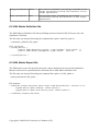
7.- ADDITIONAL FEAUTRES
7.1 Using the ARP library
The Atomium Record/Playback(ARP© ) library is a library included in the Atomium© package
provided by IMEC. It allows recording and reusing information from one simulation to another. The
functions required to record and playback timing information from SCoPE simulation have been
integrated withing M3P.
The library ARP itself is not integrated with M3P and have to be obtained from IMEC.
7.1.1 Compilation for ARP-SCoPE integration
To integrated ARP into a SCoPE simulation it is required to compile the integration files
specifically. To do so it is required to:
–
Set the environment variable ARP_LIB with the path where the ARP library is installed.
–
Go to the M3P main folder and execute “make arp_lib”
7.1.2 Using ARP-SCoPE in a simulation
To use the integration library within a simulation two steps are required.
- First it is required to prepare the source code with the corresponding marks following the
rules of the ARP library.
- When running the simulation it is required to add the ARP-LIB plugin. To do so, it is
required to add the following rule to the XML System Description file.
–
For recording data:
<Plugin name=“arp_scope” file=“libarp_scope.so” entry=“start_record” />
–
For data playback
<Plugin name=“arp_scope” file=“libarp_scope.so” entry=“start_playback” />
Additionally it is required to integrate the ARP library itself. To do so it can be added to the
application specific code when linking or it can be added with
<Plugin name=“arp_lib” file=“lib_name.so” />
(E.j. <Plugin name=“arp_lib” file=“libarp_rhel4_g++3.4.6.so” />)
Note: Make sure that the m3p/build folder and the folder of the ARP library are included in the
LD_LIBRARY_PATH environment variable.
Copyright © 2008-2010 University of Cantabria (UC)
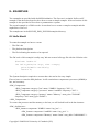
8.- EXAMPLES
Two examples are provided with the M3P distribution. The first one is a simple “hello world”
example. It has been developed to show how to create a simple example. A second version of this
example is also provided to show how to parameterize a system.
The second example is a GSM vocoder. It can show how to create a complex example and the
capabilities of the tool.
The examples are in the $SCOPE_XML_PLUGIN/examples directory.
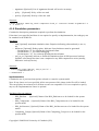
8.1 Hello World
To create the example we have to create:
–
The SW code
–
The platform descriptions
–
The file indicating the metrics to be reported.
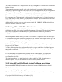
The SW code of this example is really easy. We can create a hello.cpp file with the followin code:
#include “stdio.h”
int hello_main(int argc, char **argv){
printf(“Hello world\n”);
return 0;
}
The System description required to execute that code can be also very simple.
First we have to create the HW platform. It will contain three components a processor (ARM9) a
bus, and a memory.
<HW_Components>
<HW_Component category="bus" name="AMBA" frequency="200" />
<HW_Component category="processor" name="arm926t" frequency="200" />
<HW_Component category="memory" name="Memory" mem_size="500000K"
frequency="200" mem_type="RAM" />
</HW_Components>
To connect the processor and the memory to the bus, we will include both in the bus instance:
<HW_Architecture>
<HW_Instance component="AMBA" name="my_bus" >
<HW_Instance component="arm926t" name="my_proc" />
<HW_Instance component="Memory" name="mem" start_addr=”0x80000000” />
Copyright © 2008-2010 University of Cantabria (UC)
</HW_Instance>
</HW_Architecture>
Once created the HW plaform, we have to create an component for the OS, and instantiate it in to
run over the HW processors instantiated above (“my_proc”).
<SW_Platform>
<SW_Components>
<SW_Component name="SO" type="OS" />
</SW_Components>
<SW_Architecture>
<SW_Instance name="my_OS" component="SO" HW_Resource="my_proc" />
</SW_Architecture>
</SW_Platform>
Once defined the HW and the SW infrastructure, we can indicate the SW application we want to
execute. To do that, we have to provide the name of the main function. In our case, or application
main function is called “hello_main”. We have to create a SW component with this function and
instantiate it in “My_OS”.
<Application>
<Functionality>
<Exec_Component name="hello" category="SW" function="hello_main" />
</Functionality>
<Allocation>
<Exec_Instance name="Hello_world" component="hello" os="my_OS" />
</Allocation>
</Application>
Finally, we have to indicate the simulation time. In our case, 1 second will be enough to perform the
“hello wold” application.
<Simulation time="1 s" />
Summarizing, the whole file (called “platform.xml”) is the following:
<?xml version="1.0" encoding="UTF-8"?>
<Description xmi:version="2.0" xmlns:xmi="http://www.omg.org/XMI" name="Hello_world">
<HW_Platform>
<HW_Components>
<HW_Component category="bus" name="AMBA" frequency="200" />
<HW_Component category="processor" name="arm926r" frequency="200"/
>
<HW_Component category="memory" name="Memory"
mem_size="500000K" frequency="200" mem_type="RAM" />
Copyright © 2008-2010 University of Cantabria (UC)
</HW_Components>
<HW_Architecture>
<HW_Instance component="AMBA" name="my_bus" >
<HW_Instance component="arm926t" name="my_proc" />
<HW_Instance component="Memory" name="my_memory"
start_addr="0x80000000" />
</HW_Instance>
</HW_Architecture>
</HW_Platform>
<SW_Platform>
<SW_Components>
<SW_Component name="SO" type="OS" />
</SW_Components>
<SW_Architecture>
<SW_Instance name="my_OS" component="SO" SW_Resource="my_proc"
/>
</SW_Architecture>
</SW_Platform>
<Application>
<Functionality>
<Exec_Component name="hello" category="SW" function="hello_main" />
</Functionality>
<Allocation>
<Exec_Instance name="Hello_world" component="hello"
os="my_OS" />
</Allocation>
</Application>
<Simulation time="1 s" />
</Description>
Finally, we have to create the System Metrics file, to indicate the tool which metrics have to be
reported. In our case we will ask for the latency and the power consumption. The required file
(metrics.xml) contains:
<?xml version="1.0" encoding="UTF-8"?>
<system_metrics>
<system_metric name="Latency" type="float" unit="Second"/>
<system_metric name="Power_Consumption" type="float" unit="Watts"/>
Copyright © 2008-2010 University of Cantabria (UC)
</system_metrics>
Finally, we have to compile and execute as “run.x -xsd platform.xml -xmd metrics.xml -xof
output.xml” to obtain the results of the simulation in the “output.xml” file. To make and execute it
you can type “make run”.
Once executing, first, the simulator will load the input xml files and it will create the system model.
The output provided by the example is:
SystemC 2.2.0 --- May 16 2008 09:54:21
Copyright (c) 1996-2006 by all Contributors
ALL RIGHTS RESERVED
XML System Configuration file not found.
File: platform.xml -> (OPENED)
Loading platform description.
Platform description loaded.
Creating platform.
Platform created.
File: platform.xml -> (LOADED)
Simulation time: 1 s
Then the simulation starts, and the “hello wold” is printed out.
After that, the simulation finishes and global performance information is returned:
Main finish
Simulated time: 1 s
RTOS:
0
Number of m_processes created:
Number of m_processes destroyed:
1
1
Mean process duration (process start - process end): 1.111e-06 sec
Last SW execution time:
1.111e-06 sec
processor_0_rtos_0
Number of thread switches:
100
Number of context switches: 0
Running time: 100111 ns
Use of cpu: 0.0100111%
Instructions executed: 15
Instruction cache misses: 100
Core Energy: 30 nJ
Copyright © 2008-2010 University of Cantabria (UC)
Core Power: 3e-05 mW
Instruction Cache Energy: 4045 nJ
Instruction Cache Power: 0.004045 mW
Furthermore, a “output.xml” file has been created, with the results of the metrics required in
“metrics.xml”:
<?xml version="1.0" encoding="UTF-8"?>
<simulator_output_interface xmlns="http://www.multicube.eu/" version="1.3">
<system_metric name="latency" value="0.000001111"/>
<system_metric name="power_consumption" value="0"/>
</simulator_output_interface>
8.2 Hello World Parameterized
To show how to include a parameter in a system description a new example is provided by
minimally modifying the previous one.
Let's suppose that the memory address is not completely fixed in the platform and can be moved.
Thus, instead of fixing the address as “0x80000000” in the “platform.xml” file, we will substitute
that value by “__MEM_ADDR”. The result is:
<HW_Instance component="Memory" name="my_memory" start_addr="__MEM_ADDR" />
Then we need to define this parameter in the XML System Configuration file. That file will be:
<?xml version="1.0" encoding="UTF-8"?>
<simulator_input_interface xmlns="http://www.multicube.eu/" version="1.3">
<parameter name="MEM_ADDR" value="0x80000000" />
</simulator_input_interface>
Note that in the first file, the parameter start with “__” and not in the second one. This characters
are used to detect in the system description which strings are not a real values but configurable
parameters.
Finally, we have to compile and execute as “run.x -xsd platform.xml -xsc parameter.xml -xmd
metrics.xml -xof output.xml” to obtain the results of the simulation in the “output.xml” file. To
make and execute it you can type “make run”.
The results are equal to the previous example.
Copyright © 2008-2010 University of Cantabria (UC)
8.3 Variable example
Simple example that uses a system description in SystemC code and shows how to use a variable to
configure the execution of the code.
The system contains a global variable (int global_variable=0;) declared in the variables.c file. The
variable is initialized with '0' value and printed. The variable can be configured using the XML files
to have different values depending on the execution.
In the XML System Description file the variable is defined as a configurable one:
<Simulation>
<Variable name="global_variable" value="__value"/>
</Simulation>
In the XML System Configuration file, a value is assigned:
<parameter name="value" value="13" />
Then, during the execution, the global variable has not '0' value, but '13'.
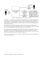
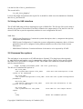
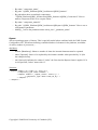
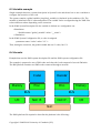
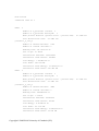
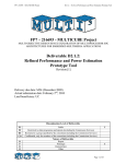
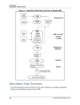
8.4 Vocoder
Example that uses the XML system description file and the XML system configuration file.
The example is prepared to run a GSM coder and a decoder, both composed of several SW tasks.
The HW platform contains two SMP nodes connected through a network.
Memory
Coder
Decoder
Proc.
Proc.
BUS
I/O
Memory
BUS
NoC IF.
NoC IF.
NoC
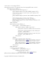
The XML platform file required to describe this platform is the following :
Copyright © 2008-2010 University of Cantabria (UC)
I/O
<?xml version="1.0" encoding="UTF-8"?>
<Description xmi:version="2.0" xmlns:xmi="http://www.omg.org/XMI" name="vocoder">
<HW_Platform name="HWPlat_1" >
<HW_Components name="HWComponents_1">
<HW_Component category="bus" name="AMBA" frequency="200" />
<HW_Component category="network" name="mesh" frequency="200"
x_size="2" y_size="1" />
<HW_Component category="processor" name="arm926t" frequency="200" /
>
<HW_Component category="memory" name="Memory"
mem_size="536870K" frequency="200" mem_type="RAM" />
<HW_Component category="net_if" name="network_if" mem_size="100"
frequency="200" />
</HW_Components>
<HW_Architecture name="HWArch_1">
<Repeat number="__NUM_NODES" index="a">
<HW_Instance component="AMBA" name="bus0" >
<HW_Instance component="arm926t" name="Processor%a" /
>
<HW_Instance component="Memory" name="Memory%a"
start_addr="__MEM_ADDR" />
<HW_Instance component="network_if" name="NoC_if%a"
start_addr="__NOC_ADDR" irq="5" />
</HW_Instance>
</Repeat>
<HW_Instance component="mesh" name="NoC" >
<HW_Connection instance="//@HW_Platform/@HW_Architecture/
@Repeat.0/@HW_Instance.0/@HW_Instance.2" name="conn0"/>
<HW_Connection instance="//@HW_Platform/@HW_Architecture/
@Repeat.1/@HW_Instance.0/@HW_Instance.2" name="conn1"/>
</HW_Instance>
</HW_Architecture>
<Computing_groups name="HWGrp_1">
<Repeat number="__NUM_NODES" index="i">
<Computing_group name="node%i" >
<Computing_Resource name="//@HW_Platform/
@HW_Architecture/@Repeat.%i/@HW_Instance.0/@HW_Instance.0" />
Copyright © 2008-2010 University of Cantabria (UC)
</Computing_group>
</Repeat>
</Computing_groups>
</HW_Platform>
<SW_Platform name="SWPlat_1">
<SW_Components name="SWPlat_1">
<SW_Component name="SO" type="OS" />
</SW_Components>
<SW_Architecture name="SWArch_1">
<Repeat number="__NUM_NODES" index="i">
<SW_Instance name="OS%i" component="SO"
HW_Resource="node%i" />
</Repeat>
</SW_Architecture>
<Functionality name="Func_1">
<Exec_Component name="Coder" category="SW" function="coder_main"
file="./functions.o" />
<Exec_Component name="Decoder" category="SW"
function="decoder_main" file="./functions.o" />
<Exec_Component name="tun" category="driver" function="tun_init"
file="./functions.o" />
</Functionality>
</SW_Platform>
<Application>
<Allocation name="Alloc_1">
<Exec_Instance name="_Coder" component="Coder" resource="node0" />
<Exec_Instance name="_Decoder" component="Decoder"
resource="node1" />
<Exec_Instance name="tun0" component="tun" resource="node0" />
<Exec_Instance name="tun1" component="tun" resource="node1" />
</Allocation>
<Allocation name="Alloc_2">
<Exec_Instance name="_Coder" component="Coder" resource="node1" />
<Exec_Instance name="_Decoder" component="Decoder"
resource="node2" />
<Exec_Instance name="tun0" component="tun" resource="node0" />
<Exec_Instance name="tun1" component="tun" resource="node1" />
Copyright © 2008-2010 University of Cantabria (UC)
</Allocation>
</Application>
<Simulation time="40 s" >
<Implementation HW_Components="HWComponents_1" Allocation="Alloc_1"/>
</Simulation>
</Description>
To completely define the platform, some parameters has to be fixed. The required configuration file
is:
<?xml version="1.0" encoding="UTF-8"?>
<simulator_input_interface xmlns="http://www.multicube.eu/" version="1.0">
<parameter name="MEM_ADDR" value="0x80000000" />
<parameter name="NOC_ADDR" value="0x60000000" />
<parameter name="NUM_NODES" value="2" />
</simulator_input_interface>
Once executed, the output obtained in the shell is:
SystemC 2.2.0 --- May 16 2008 09:54:21
Copyright (c) 1996-2006 by all Contributors
ALL RIGHTS RESERVED
File: parameter.xml -> (OPENED)
Loading configuration parameters.
Configuration parameters loaded.
File: parameter.xml -> (LOADED)
File: platform.xml -> (OPENED)
Loading platform description.
Platform description loaded.
Creating platform.
Platform created.
File: platform.xml -> (LOADED)
Simulation time: 40 s
Copyright © 2008-2010 University of Cantabria (UC)
Main finish
Simulated time: 40 s
RTOS:
0
Number of m_processes created:
1
Number of m_processes destroyed:
1
Mean process duration (process start - process end):
Last SW execution time:
27.3985 sec
27.3985 sec
processor_0_rtos_0
Number of thread switches:
6739
Number of context switches: 0
Running time: 27177315700 ns
Use of cpu: 67.9433%
Instructions executed: 3667971480
Instruction cache misses: 1400881
Core Energy: 7.33594e+09 nJ
Core Power: 183.399 mW
Instruction Cache Energy: 1.10599e+10 nJ
Instruction Cache Power: 276.499 mW
RTOS:
1
Number of m_processes created:
1
Number of m_processes destroyed:
1
Mean process duration (process start - process end):
Last SW execution time:
27.3981 sec
processor_0_rtos_1
Number of thread switches:
4882
Number of context switches: 0
Running time: 3082860608 ns
Use of cpu: 7.70715%
Instructions executed: 415470102
Instruction cache misses: 393756
Core Energy: 8.3094e+08 nJ
Core Power: 20.7735 mW
Instruction Cache Energy: 1.26216e+09 nJ
Instruction Cache Power: 31.554 mW
Copyright © 2008-2010 University of Cantabria (UC)
27.3981 sec
Copyright © 2008-2010 University of Cantabria (UC)
9.- Glossary
Application Programing Interface (API): Set of routines, data structures, object
classes and/or protocols provided by libraries and/or operating system services
in order to support the building of applications.
Approximately timed: Modeling style for which there exists a one-to-one mapping
between the externally observable states of the model and the states of some
corresponding detailed reference model such that the mapping preserves the
sequence of state transitions but not their precise timing.
Computing group: Group of computing elements, usually processors, organized to
work cooperatively, emulating a more powerful single computing unit. The
elements of the computing group work controlled by a single operating simple and
usually in a symmetric way.
Design Space Exploration (DSE): Process that explores all the system design
possibilities in order to obtain an optimal design.
Extensible Markup Language (XML): General-purpose specification for creating
custom markup languages. It is classified as an extensible language, because it
allows the user to define the mark-up elements. XML's purpose is to aid
information systems in sharing structured data, especially via the Internet, to
encode documents, and to serialize data.
HW platform: Group of HW components working together that provides the required
support to the SW components and provided the required specific functionality
required to perform the required application(s).
HW/SW partition: Process of dividing the system functionality in SW and HW
components.
Instruction Set Simulator (ISS): Simulation model, usually coded in a high-level
programming language, which mimics the behavior of a mainframe or microprocessor
by "reading" binary instructions and maintaining internal variables which
represent the processor's registers.
Metric: Set of units which can be used to specify anything which can be
measured, along with the procedures to carry out measurements and the procedures
for the interpretation of the assessment in the light of previous or comparable
assessments.
Metric Definition file: XML file listing the system metrics the simulation must
measure and report.
Network on Chip (NoC): Is a new approach to System-on-a-chip (SoC) design. NoCbased systems can accommodate multiple asynchronous clocking that many of
today's complex SoC designs use. The NoC solution brings a networking method to
on-chip communication and brings notable improvements over conventional bus
systems
Node: Active electronic device or group of devices attached to a network, and
capable of sending, receiving, or forwarding information over a communications
channel. A node is a connection point, either a redistribution point or a
communication endpoint.
Platform: Sort of hardware architecture or software framework (including
application frameworks), that allows software to run. Typical platforms include
a computer's architecture, operating system, programming languages and related
runtime libraries or graphical user interface.
Real-Time Operating System (RTOS): Multitasking operating system intended for
real-time applications. Such applications include embedded systems , industrial
robots, spacecraft, industrial control, and scientific research equipment. A
Copyright © 2008-2010 University of Cantabria (UC)
RTOS facilitates the creation of a real-time system, but does not guarantee the
final result will be real-time; this requires correct development of the
software. Key factors in an RTOS are therefore a minimal interrupt latency and a
minimal thread switching latency.
SW platform: Group of generic SW components used to provide the required support
to the SW applications.
System Configuration file: XML file defining the values required for the system
configuration parameters to perform a simulation.
System Descriptions file: XML file describing the system. It contains a
description of the HW platform, SW platform and SW application.
System Metrics file: XML file where the obtained estimation for the system
metrics are reported.
SystemC: Set of library routines and macros implemented in C++, which makes it
possible to simulate concurrent processes, each described by ordinary C++
syntax. Instantiated in the SystemC framework, the objects described in this
manner may communicate in a simulated real-time environment, using signals of
all the datatypes offered by C++, some additional ones offered by the SystemC
library, as well as user defined.
SCoPE: SystemC framework for system modeling based on approximately (loosely)
timed descriptions of the system components.
Timed simulation: Simulation performed using timed models of the system
components. The resulting simulation considers both the system functionality and
the associated timing.
Transaction-Level Modeling (TLM): High-level approach to modeling digital
systems where details of communication among modules are separated from the
details of the implementation of functional units or of the communication
architecture. Transaction requests take place by calling interface functions of
these channel models, which encapsulate low-level details of the information
exchange. Communication mechanisms are modeled using channels, such as busses or
FIFOs.
TLM2: The second major version of the OSCI Transaction Level Modeling standard.
Copyright © 2008-2010 University of Cantabria (UC)