1
PowerFlex® Digital DC Drive
USER MANUAL
Firmware Version 1.006
Important User Information
Solid state equipment has operational characteristics differing from those of
electromechanical equipment. Safety Guidelines for the Application,
Installation and Maintenance of Solid State Controls (Publication SGI-1.1
available from your local Rockwell Automation sales office or online at http://
www.rockwellautomation.com/literature) describes some important differences
between solid state equipment and hard-wired electromechanical devices.
Because of this difference, and also because of the wide variety of uses for solid
state equipment, all persons responsible for applying this equipment must
satisfy themselves that each intended application of this equipment is
acceptable.
In no event will Rockwell Automation, Inc. be responsible or liable for indirect
or consequential damages resulting from the use or application of this
equipment.
The examples and diagrams in this manual are included solely for illustrative
purposes. Because of the many variables and requirements associated with any
particular installation, Rockwell Automation, Inc. cannot assume responsibility
or liability for actual use based on the examples and diagrams.
No patent liability is assumed by Rockwell Automation, Inc. with respect to use
of information, circuits, equipment, or software described in this manual.
Reproduction of the contents of this manual, in whole or in part, without
written permission of Rockwell Automation, Inc. is prohibited.
Throughout this manual, when necessary we use notes to make you aware of
safety considerations.
!
WARNING: Identifies information about practices or
circumstances that can cause an explosion in a hazardous
environment, which may lead to personal injury or death, property
damage, or economic loss.
Important: Identifies information that is critical for successful application and
understanding of the product.
!
ATTENTION: Identifies information about practices or
circumstances that can lead to personal injury or death, property
damage, or economic loss. Attentions help you identify a hazard,
avoid a hazard, and recognize the consequences.
Shock Hazard labels may be located on or inside the equipment
(e.g., drive or motor) to alert people that dangerous voltage may be
present.
Burn Hazard labels may be located on or inside the equipment
(e.g., drive or motor) to alert people that surfaces may be at
dangerous temperatures.
PowerFlex, DriveExplorer, DriveTools SP, DPI, and SCANport are either trademarks or registered trademarks of Rockwell Automation, Inc.
Klixon® is a registered trademark of Sensata Technologies, Inc.
Summary of Changes
The information below summarizes the changes to the PowerFlex Digital
DC Drive User Manual, publication 20-UM001… since the last release.
Manual Updates
Change
Page(s)
Removed erroneous derating information.
Updated AC Input Voltages tables.
Updated “AnalogCflct” Alarm description to include parameters 1323-1327 [DPI Px Select].
Updated Agency Certification Information.
Added notation regarding required installation in a Pollution Degree 2 environment.
Updated the Maximum Short Circuit Ratings data.
Added footnote regarding coil voltage to DC Loop Contactor table information.
Updated block diagrams to correct parameter numbers and names.
1-1, A-1
1-12
4-7
A-1
A-1
A-2
A-18
D-2
soc-ii
Notes:
Table of Contents
Important User Information . . . . . . . . . . . . . . . . . . . . . . . . . . . . . . . . . . . . . . . . . . . . . . . 1-2
Manual Updates. . . . . . . . . . . . . . . . . . . . . . . . . . . . . . . . . . . . . . . . . . . . . . . . . . . . . . soc-i
Preface
Overview
Who Should Use this Manual? . . . . . . . . . . . . . . . . . . . . . . . . . . . . . . . . . . . . . . . . . . . . .
What is in this Manual?. . . . . . . . . . . . . . . . . . . . . . . . . . . . . . . . . . . . . . . . . . . . . . . . . . .
Drive Storage Conditions . . . . . . . . . . . . . . . . . . . . . . . . . . . . . . . . . . . . . . . . . . . . . . . . .
Drive Nameplate Data . . . . . . . . . . . . . . . . . . . . . . . . . . . . . . . . . . . . . . . . . . . . . . . . . . . .
Drive Frame Sizes . . . . . . . . . . . . . . . . . . . . . . . . . . . . . . . . . . . . . . . . . . . . . . . . . . . . . . .
Reference Materials . . . . . . . . . . . . . . . . . . . . . . . . . . . . . . . . . . . . . . . . . . . . . . . . . . . . .
Manual Conventions . . . . . . . . . . . . . . . . . . . . . . . . . . . . . . . . . . . . . . . . . . . . . . . . . . . . .
General Precautions . . . . . . . . . . . . . . . . . . . . . . . . . . . . . . . . . . . . . . . . . . . . . . . . . . . . .
Catalog Number Explanation . . . . . . . . . . . . . . . . . . . . . . . . . . . . . . . . . . . . . . . . . . . . . .
Chapter 1
p-1
p-1
p-1
p-2
p-2
p-2
p-3
p-3
p-4
Installation and Wiring
Mounting Considerations . . . . . . . . . . . . . . . . . . . . . . . . . . . . . . . . . . . . . . . . . . . . . . . . . 1-1
Operating Conditions and Temperatures. . . . . . . . . . . . . . . . . . . . . . . . . . . . . . . . . . . . 1-1
Minimum Mounting Clearances . . . . . . . . . . . . . . . . . . . . . . . . . . . . . . . . . . . . . . . . . . 1-2
Mounting Dimensions and Weights . . . . . . . . . . . . . . . . . . . . . . . . . . . . . . . . . . . . . . . . . 1-2
Lifting PowerFlex DC Drives . . . . . . . . . . . . . . . . . . . . . . . . . . . . . . . . . . . . . . . . . . . . . . 1-5
Mounting Frame C Drives. . . . . . . . . . . . . . . . . . . . . . . . . . . . . . . . . . . . . . . . . . . . . . . 1-6
Removing the Drive Covers . . . . . . . . . . . . . . . . . . . . . . . . . . . . . . . . . . . . . . . . . . . . . . . 1-7
Frame A Drives . . . . . . . . . . . . . . . . . . . . . . . . . . . . . . . . . . . . . . . . . . . . . . . . . . . . . . . 1-7
Frame B and C Drives . . . . . . . . . . . . . . . . . . . . . . . . . . . . . . . . . . . . . . . . . . . . . . . . . . 1-8
Line Reactors / Filters . . . . . . . . . . . . . . . . . . . . . . . . . . . . . . . . . . . . . . . . . . . . . . . . . . . . 1-9
Using Contactors . . . . . . . . . . . . . . . . . . . . . . . . . . . . . . . . . . . . . . . . . . . . . . . . . . . . . . . . 1-9
AC Input Contactors . . . . . . . . . . . . . . . . . . . . . . . . . . . . . . . . . . . . . . . . . . . . . . . . . . 1-10
DC Output Contactors. . . . . . . . . . . . . . . . . . . . . . . . . . . . . . . . . . . . . . . . . . . . . . . . . 1-10
Dynamic Brake Resistors . . . . . . . . . . . . . . . . . . . . . . . . . . . . . . . . . . . . . . . . . . . . . . 1-10
Control Power Protection . . . . . . . . . . . . . . . . . . . . . . . . . . . . . . . . . . . . . . . . . . . . . . . . 1-10
General Grounding Requirements. . . . . . . . . . . . . . . . . . . . . . . . . . . . . . . . . . . . . . . . . . 1-11
Safety Ground (PE) . . . . . . . . . . . . . . . . . . . . . . . . . . . . . . . . . . . . . . . . . . . . . . . . . . . 1-11
Power Feeder. . . . . . . . . . . . . . . . . . . . . . . . . . . . . . . . . . . . . . . . . . . . . . . . . . . . . . . . 1-12
Encoder Ground Connections . . . . . . . . . . . . . . . . . . . . . . . . . . . . . . . . . . . . . . . . . . . 1-12
Tachometer Ground Connections . . . . . . . . . . . . . . . . . . . . . . . . . . . . . . . . . . . . . . . . 1-12
Power Circuit Protection . . . . . . . . . . . . . . . . . . . . . . . . . . . . . . . . . . . . . . . . . . . . . . . . . 1-12
Power Wiring. . . . . . . . . . . . . . . . . . . . . . . . . . . . . . . . . . . . . . . . . . . . . . . . . . . . . . . . . . 1-12
AC Input Voltages . . . . . . . . . . . . . . . . . . . . . . . . . . . . . . . . . . . . . . . . . . . . . . . . . . . . 1-12
DC Output Voltages . . . . . . . . . . . . . . . . . . . . . . . . . . . . . . . . . . . . . . . . . . . . . . . . . . 1-13
Typical Power Wiring Diagrams . . . . . . . . . . . . . . . . . . . . . . . . . . . . . . . . . . . . . . . . . 1-13
Armature Converter Connections . . . . . . . . . . . . . . . . . . . . . . . . . . . . . . . . . . . . . . . . 1-16
Field Circuit Connections . . . . . . . . . . . . . . . . . . . . . . . . . . . . . . . . . . . . . . . . . . . . . . 1-19
Field Current Resistors . . . . . . . . . . . . . . . . . . . . . . . . . . . . . . . . . . . . . . . . . . . . . . . . 1-20
Relay Outputs . . . . . . . . . . . . . . . . . . . . . . . . . . . . . . . . . . . . . . . . . . . . . . . . . . . . . . . 1-21
Thermistors and Thermal Switches. . . . . . . . . . . . . . . . . . . . . . . . . . . . . . . . . . . . . . . 1-21
Control Circuit Input Power . . . . . . . . . . . . . . . . . . . . . . . . . . . . . . . . . . . . . . . . . . . . 1-24
Frame C Heatsink Cooling Fans and Internal Fuse Signal Terminals . . . . . . . . . . . . 1-26
2
I/O Wiring . . . . . . . . . . . . . . . . . . . . . . . . . . . . . . . . . . . . . . . . . . . . . . . . . . . . . . . . . . . .
DIP Switch and Jumper Settings . . . . . . . . . . . . . . . . . . . . . . . . . . . . . . . . . . . . . . . . .
I/O Signal and Control Wiring. . . . . . . . . . . . . . . . . . . . . . . . . . . . . . . . . . . . . . . . . . .
I/O Wiring Examples . . . . . . . . . . . . . . . . . . . . . . . . . . . . . . . . . . . . . . . . . . . . . . . . .
Digital Encoder Terminal Block . . . . . . . . . . . . . . . . . . . . . . . . . . . . . . . . . . . . . . . . .
DC Analog Tachometer Terminal Block . . . . . . . . . . . . . . . . . . . . . . . . . . . . . . . . . .
Chapter 2
1-27
1-28
1-31
1-33
1-36
1-38
Drive Start Up
Drive Start Up Checklist . . . . . . . . . . . . . . . . . . . . . . . . . . . . . . . . . . . . . . . . . . . . . . . . . . 2-1
Before Applying Power to the Drive . . . . . . . . . . . . . . . . . . . . . . . . . . . . . . . . . . . . . . . . . 2-2
Applying Power to the Drive . . . . . . . . . . . . . . . . . . . . . . . . . . . . . . . . . . . . . . . . . . . . . . . 2-3
Speed-Up Function . . . . . . . . . . . . . . . . . . . . . . . . . . . . . . . . . . . . . . . . . . . . . . . . . . . 2-16
Configuring the Speed Zero Logic . . . . . . . . . . . . . . . . . . . . . . . . . . . . . . . . . . . . . . . 2-16
Adaptive Speed Regulation . . . . . . . . . . . . . . . . . . . . . . . . . . . . . . . . . . . . . . . . . . . . . 2-16
Chapter 3
Programming and Parameters
About Parameters. . . . . . . . . . . . . . . . . . . . . . . . . . . . . . . . . . . . . . . . . . . . . . . . . . . . . . . . 3-1
How Parameters are Organized . . . . . . . . . . . . . . . . . . . . . . . . . . . . . . . . . . . . . . . . . . . . . 3-3
File–Group–Parameter Order . . . . . . . . . . . . . . . . . . . . . . . . . . . . . . . . . . . . . . . . . . . . 3-3
Numbered List View . . . . . . . . . . . . . . . . . . . . . . . . . . . . . . . . . . . . . . . . . . . . . . . . . . . 3-3
Cross Reference Tables . . . . . . . . . . . . . . . . . . . . . . . . . . . . . . . . . . . . . . . . . . . . . . . . . 3-3
Basic Parameter View . . . . . . . . . . . . . . . . . . . . . . . . . . . . . . . . . . . . . . . . . . . . . . . . . . 3-4
Advanced Parameter View. . . . . . . . . . . . . . . . . . . . . . . . . . . . . . . . . . . . . . . . . . . . . . . 3-6
Monitor File . . . . . . . . . . . . . . . . . . . . . . . . . . . . . . . . . . . . . . . . . . . . . . . . . . . . . . . . 3-11
Motor Control File . . . . . . . . . . . . . . . . . . . . . . . . . . . . . . . . . . . . . . . . . . . . . . . . . . . 3-14
Speed Command File . . . . . . . . . . . . . . . . . . . . . . . . . . . . . . . . . . . . . . . . . . . . . . . . . 3-23
Dynamic Control File . . . . . . . . . . . . . . . . . . . . . . . . . . . . . . . . . . . . . . . . . . . . . . . . . 3-28
Applications File . . . . . . . . . . . . . . . . . . . . . . . . . . . . . . . . . . . . . . . . . . . . . . . . . . . . . 3-33
Utility File . . . . . . . . . . . . . . . . . . . . . . . . . . . . . . . . . . . . . . . . . . . . . . . . . . . . . . . . . . 3-45
Communications File . . . . . . . . . . . . . . . . . . . . . . . . . . . . . . . . . . . . . . . . . . . . . . . . . 3-57
Input / Output File . . . . . . . . . . . . . . . . . . . . . . . . . . . . . . . . . . . . . . . . . . . . . . . . . . . . 3-61
Parameter Cross Reference – by Name . . . . . . . . . . . . . . . . . . . . . . . . . . . . . . . . . . . . . . 3-71
Parameter Cross Reference – by Number . . . . . . . . . . . . . . . . . . . . . . . . . . . . . . . . . . . . 3-76
Chapter 4
Troubleshooting
Faults and Alarms . . . . . . . . . . . . . . . . . . . . . . . . . . . . . . . . . . . . . . . . . . . . . . . . . . . . . . . 4-1
Drive Status . . . . . . . . . . . . . . . . . . . . . . . . . . . . . . . . . . . . . . . . . . . . . . . . . . . . . . . . . . . . 4-2
HIM Indication . . . . . . . . . . . . . . . . . . . . . . . . . . . . . . . . . . . . . . . . . . . . . . . . . . . . . . . 4-3
Manually Clearing Faults. . . . . . . . . . . . . . . . . . . . . . . . . . . . . . . . . . . . . . . . . . . . . . . . . . 4-3
Fault Descriptions . . . . . . . . . . . . . . . . . . . . . . . . . . . . . . . . . . . . . . . . . . . . . . . . . . . . . . . 4-4
Clearing Alarms. . . . . . . . . . . . . . . . . . . . . . . . . . . . . . . . . . . . . . . . . . . . . . . . . . . . . . . . . 4-7
Alarm Descriptions . . . . . . . . . . . . . . . . . . . . . . . . . . . . . . . . . . . . . . . . . . . . . . . . . . . . . . 4-7
Common Drive Symptoms and Corrective Actions . . . . . . . . . . . . . . . . . . . . . . . . . . . . 4-10
Drive will not start . . . . . . . . . . . . . . . . . . . . . . . . . . . . . . . . . . . . . . . . . . . . . . . . . . . . 4-10
Drive starts but motor does not turn and no armature current. . . . . . . . . . . . . . . . . . . 4-12
The motor does not reach commanded speed.. . . . . . . . . . . . . . . . . . . . . . . . . . . . . . . 4-13
The motor is turning the wrong direction. . . . . . . . . . . . . . . . . . . . . . . . . . . . . . . . . . . 4-13
The motor reaches maximum speed immediately.. . . . . . . . . . . . . . . . . . . . . . . . . . . . 4-14
Testpoint Codes and Functions . . . . . . . . . . . . . . . . . . . . . . . . . . . . . . . . . . . . . . . . . . . . 4-14
3
Appendix A
Supplemental Drive Information
Specifications . . . . . . . . . . . . . . . . . . . . . . . . . . . . . . . . . . . . . . . . . . . . . . . . . . . . . . . . . . A-1
IP20 (NEMA UL/Type Open) Watts Loss . . . . . . . . . . . . . . . . . . . . . . . . . . . . . . . . . . . . A-4
Communication Configurations . . . . . . . . . . . . . . . . . . . . . . . . . . . . . . . . . . . . . . . . . . . . A-4
Typical Programmable Controller Configurations . . . . . . . . . . . . . . . . . . . . . . . . . . . . A-4
Logic Command/Status Words . . . . . . . . . . . . . . . . . . . . . . . . . . . . . . . . . . . . . . . . . . . A-5
Drive Power Circuit Protection . . . . . . . . . . . . . . . . . . . . . . . . . . . . . . . . . . . . . . . . . . . . . A-7
Frame A and B Fuse Information . . . . . . . . . . . . . . . . . . . . . . . . . . . . . . . . . . . . . . . . . A-7
Frame C Fuse Information . . . . . . . . . . . . . . . . . . . . . . . . . . . . . . . . . . . . . . . . . . . . . A-11
Control Power Circuit Protection Fuses . . . . . . . . . . . . . . . . . . . . . . . . . . . . . . . . . . . . . A-14
AC Input Line Reactors and AC Input Contactors . . . . . . . . . . . . . . . . . . . . . . . . . . . . . A-16
DC Output Contactors and Dynamic Brake Resistor Kits . . . . . . . . . . . . . . . . . . . . . . . A-18
Appendix B
HIM Overview
External and Internal Connections . . . . . . . . . . . . . . . . . . . . . . . . . . . . . . . . . . . . . . . . . .
LCD Display Elements . . . . . . . . . . . . . . . . . . . . . . . . . . . . . . . . . . . . . . . . . . . . . . . . . . .
ALT Functions. . . . . . . . . . . . . . . . . . . . . . . . . . . . . . . . . . . . . . . . . . . . . . . . . . . . . . . . . .
Using the S.M.A.R.T. List Screen. . . . . . . . . . . . . . . . . . . . . . . . . . . . . . . . . . . . . . . . .
Menu Structure . . . . . . . . . . . . . . . . . . . . . . . . . . . . . . . . . . . . . . . . . . . . . . . . . . . . . . . . .
Viewing and Editing Parameters . . . . . . . . . . . . . . . . . . . . . . . . . . . . . . . . . . . . . . . . . . . .
LCD HIM . . . . . . . . . . . . . . . . . . . . . . . . . . . . . . . . . . . . . . . . . . . . . . . . . . . . . . . . . . .
Removing/Installing the HIM . . . . . . . . . . . . . . . . . . . . . . . . . . . . . . . . . . . . . . . . . . . . . .
Appendix C
B-1
B-1
B-2
B-2
B-3
B-5
B-5
B-5
Application Notes
Analog Input Configuration . . . . . . . . . . . . . . . . . . . . . . . . . . . . . . . . . . . . . . . . . . . . . . . C-1
Example 1:. . . . . . . . . . . . . . . . . . . . . . . . . . . . . . . . . . . . . . . . . . . . . . . . . . . . . . . . . . . C-1
Example 2:. . . . . . . . . . . . . . . . . . . . . . . . . . . . . . . . . . . . . . . . . . . . . . . . . . . . . . . . . . . C-2
Analog Input Signal Comparison . . . . . . . . . . . . . . . . . . . . . . . . . . . . . . . . . . . . . . . . . C-2
Current / Speed Curve . . . . . . . . . . . . . . . . . . . . . . . . . . . . . . . . . . . . . . . . . . . . . . . . . . . . C-4
Droop Compensation . . . . . . . . . . . . . . . . . . . . . . . . . . . . . . . . . . . . . . . . . . . . . . . . . . . . C-5
PID Function . . . . . . . . . . . . . . . . . . . . . . . . . . . . . . . . . . . . . . . . . . . . . . . . . . . . . . . . . . . C-5
Configure a Line Speed Signal . . . . . . . . . . . . . . . . . . . . . . . . . . . . . . . . . . . . . . . . . . . C-6
Configure the Feedback Signal in the Follower Drive(s) . . . . . . . . . . . . . . . . . . . . . . . C-7
Configure the Tension Set Point Signal in the Follower Drive(s) . . . . . . . . . . . . . . . . . C-9
Reference Control . . . . . . . . . . . . . . . . . . . . . . . . . . . . . . . . . . . . . . . . . . . . . . . . . . . . . . C-10
“Auto” Speed Sources . . . . . . . . . . . . . . . . . . . . . . . . . . . . . . . . . . . . . . . . . . . . . . . . . C-10
“Manual” Speed Sources. . . . . . . . . . . . . . . . . . . . . . . . . . . . . . . . . . . . . . . . . . . . . . . C-10
Changing Speed Sources. . . . . . . . . . . . . . . . . . . . . . . . . . . . . . . . . . . . . . . . . . . . . . . C-10
Torque Reference Source . . . . . . . . . . . . . . . . . . . . . . . . . . . . . . . . . . . . . . . . . . . . . . C-11
Auto/Manual Examples. . . . . . . . . . . . . . . . . . . . . . . . . . . . . . . . . . . . . . . . . . . . . . . . C-11
Speed Feedback. . . . . . . . . . . . . . . . . . . . . . . . . . . . . . . . . . . . . . . . . . . . . . . . . . . . . . . . C-12
Scale Blocks . . . . . . . . . . . . . . . . . . . . . . . . . . . . . . . . . . . . . . . . . . . . . . . . . . . . . . . . . . C-13
Linking Parameters Via the Scale Block Parameters . . . . . . . . . . . . . . . . . . . . . . . . . C-14
Speed Regulation Functions . . . . . . . . . . . . . . . . . . . . . . . . . . . . . . . . . . . . . . . . . . . . . . C-14
Adaptive Speed Regulator. . . . . . . . . . . . . . . . . . . . . . . . . . . . . . . . . . . . . . . . . . . . . . C-14
Speed Up Function . . . . . . . . . . . . . . . . . . . . . . . . . . . . . . . . . . . . . . . . . . . . . . . . . . . C-17
Speed Threshold Indicators. . . . . . . . . . . . . . . . . . . . . . . . . . . . . . . . . . . . . . . . . . . . . C-17
Speed Zero Function . . . . . . . . . . . . . . . . . . . . . . . . . . . . . . . . . . . . . . . . . . . . . . . . . . C-19
Speed Draw Function . . . . . . . . . . . . . . . . . . . . . . . . . . . . . . . . . . . . . . . . . . . . . . . . . C-19
Start At Powerup . . . . . . . . . . . . . . . . . . . . . . . . . . . . . . . . . . . . . . . . . . . . . . . . . . . . . . . C-21
4
Fine Tuning the Regulators . . . . . . . . . . . . . . . . . . . . . . . . . . . . . . . . . . . . . . . . . . . . . . .
Manually Adjusting the Current Regulator Tune Settings. . . . . . . . . . . . . . . . . . . . . .
Fine Tuning the Field Current Regulator. . . . . . . . . . . . . . . . . . . . . . . . . . . . . . . . . . .
Fine Tuning the Speed Regulator. . . . . . . . . . . . . . . . . . . . . . . . . . . . . . . . . . . . . . . . .
Fine Tuning the Voltage Regulator in the Field Converter . . . . . . . . . . . . . . . . . . . . .
Tuning the Field Current Curve . . . . . . . . . . . . . . . . . . . . . . . . . . . . . . . . . . . . . . . . . .
Appendix D
C-22
C-22
C-23
C-26
C-28
C-30
Control Block Diagrams
Diagram Conventions . . . . . . . . . . . . . . . . . . . . . . . . . . . . . . . . . . . . . . . . . . . . . . . . . . D-1
Appendix E
Installing a Communication Adapter
Communication Adapter Kits . . . . . . . . . . . . . . . . . . . . . . . . . . . . . . . . . . . . . . . . . . . . . .
What The Communication Adapter Kit Includes . . . . . . . . . . . . . . . . . . . . . . . . . . . . . . .
Tools That You Need . . . . . . . . . . . . . . . . . . . . . . . . . . . . . . . . . . . . . . . . . . . . . . . . . . . . .
Safety Precautions . . . . . . . . . . . . . . . . . . . . . . . . . . . . . . . . . . . . . . . . . . . . . . . . . . . . . . .
Installing the Communication Adapter Module in the Drive . . . . . . . . . . . . . . . . . . . . . .
Appendix F
E-1
E-1
E-1
E-2
E-2
Optional Analog and Digital I/O Expansion Circuit Board
What This Option Board Provides. . . . . . . . . . . . . . . . . . . . . . . . . . . . . . . . . . . . . . . . . . . F-1
I/O Expansion Board Wiring . . . . . . . . . . . . . . . . . . . . . . . . . . . . . . . . . . . . . . . . . . . . . . . F-1
Appendix G
Optional 115V AC to 24V DC I/O Converter Circuit Board
What This Option Board Provides. . . . . . . . . . . . . . . . . . . . . . . . . . . . . . . . . . . . . . . . . . . G-1
I/O Converter Board Wiring . . . . . . . . . . . . . . . . . . . . . . . . . . . . . . . . . . . . . . . . . . . . . . . G-2
Index
Preface
Overview
The purpose of this manual is to provide you with the basic information
needed to install, start-up and troubleshoot the PowerFlex DC drive.
For information on . . .
Who Should Use this Manual?
What is in this Manual?
Drive Storage Conditions
Drive Nameplate Data
Reference Materials
Drive Frame Sizes
Manual Conventions
General Precautions
Catalog Number Explanation
See page . . .
Preface-1
Preface-1
Preface-1
Preface-2
Preface-2
Preface-2
Preface-3
Preface-3
Preface-4
Who Should Use this
Manual?
This manual is intended for qualified personnel. You must be able to
program and operate DC drives. In addition, you must have an
understanding of the parameter settings and functions detailed in this
manual.
What is in this Manual?
The PowerFlex DC User Manual is designed to provide installation, basic
start-up information, and drive parameter definitions. For detailed drive
information, please refer to “Reference Materials” on page Preface-2 for a
list of additional publications.
Drive Storage Conditions
If it is necessary to store the drive for any length of time before installation,
follow these storage guidelines in order to ensure satisfactory operation at
start up and to maintain warranty coverage:
• After receipt and inspection, repack the drive in its original shipping
container and store in a clean, dry place.
• Place where the ambient temperatures do not exceed -25° C (-13° F) or
+55° C (131° F)
• Place where the relative air humidity range does not exceed 5% - 95%.
• At an altitude of less than 3,000 meters (10,000 ft.) above sea level.
Overview
The PowerFlex DC drive contains a data nameplate located on the side of
each drive that identifies the specific model number design, applicable AC
input power and DC output power data. All communication with Rockwell
Automation personnel concerning this product should include this
information.
Cat No.
20P41AD4P1RA0NNN
UL Type OPEN/IP20
Series: A
Input: 460VAC 50/60 Hz 3.3A 3 Phase
I/O: 24VDC (Standard)
Original Firmware V. 1.001
Output: 500VDC 4.1A REGEN 1.0HP
1 Min Overload Amps
6.2
3 Sec Overload Amps
8.2
LY
Drive Nameplate Data
N223
Note: Certification
Marks Location.
C
ON
p-2
R
US
Listed
Ind. Cont.
Eq. 31KF
Refer to the data
nameplate label
on your drive for
actual agency
certifications.
AM
PL
E
DC Field:
Input: 460VAC 50/60 Hz 10A max. 1 Phase
Output: 360VDC 10A max.
EX
Regulator Power: 115/230VAC 50/60 Hz 1.0/0.5A 1 Phase
MFD. in 2XXX on MMM DD
Frame: A
Serial Number: A23E0042
Made in Italy
Drive Frame Sizes
Similar PowerFlex DC drive sizes are grouped into frame sizes to simplify
spare parts ordering, dimensioning, etc. Refer to the Catalog Number
Explanation on page Preface-4 for a list of drive catalog numbers and their
respective frame sizes.
Reference Materials
The following manuals are recommended for general drive information:
Title
Preventive Maintenance of Industrial Control and
Drive System Equipment
Safety Guidelines for the Application, Installation
and Maintenance of Solid State Control
A Global Reference Guide for Reading Schematic
Diagrams
Guarding Against Electrostatic Damage
Publication
Available Online at . . .
DRIVES-TD001…
SGI-1.1
100-2.10
www.rockwellautomation.
com/literature
8000-4.5.2
For Allen-Bradley Drives Technical Support:
Title
Allen-Bradley Drives Technical Support
Online at . . .
www.ab.com/support/abdrives
Overview
Manual Conventions
p-3
• To help differentiate parameter names and LCD display text from other
text, the following conventions will be used:
– Parameter Names will appear in [brackets].
For example: [Armature Voltage].
– Display Text will appear in “quotes.” For example: “Enabled.”
• The following words are used throughout the manual to describe an
action:
Word
Can
Cannot
Meaning
Possible, able to do something
Not possible, not able to do
something
May
Permitted, allowed
Must
Unavoidable, you must do this
Shall
Required and necessary
Should
Recommended
Should Not Not recommended
General Precautions
!
!
!
!
ATTENTION: This drive contains ESD (Electrostatic
Discharge) sensitive parts and assemblies. Static control
precautions are required when installing, testing, servicing or
repairing this assembly. Component damage may result if ESD
control procedures are not followed. If you are not familiar with
static control procedures, reference A-B publication 8000-4.5.2,
“Guarding Against Electrostatic Damage” or any other applicable
ESD protection handbook.
ATTENTION: An incorrectly applied or installed drive can
result in component damage or a reduction in product life. Wiring
or application errors, such as, undersizing the motor, incorrect or
inadequate AC supply, or excessive surrounding air temperatures
may result in malfunction of the system.
ATTENTION: Only qualified personnel familiar with DC drives
and associated machinery should plan or implement the
installation, start-up and subsequent maintenance of the system.
Failure to comply may result in personal injury and/or equipment
damage.
ATTENTION: An incorrectly applied or installed bypass system
can result in component damage or reduction in product life. The
most common causes are:
• Wiring AC line to drive output or control terminals.
• Improper bypass or output circuits not approved by
Allen-Bradley.
• Output circuits which do not connect directly to the motor.
Contact Allen-Bradley for assistance with application or wiring.
p-4
Overview
Catalog Number
Explanation
Position
1-3
4
5
6
7
8-10
20P
4
1
A
D
4P1
a
b
c
d
e
11
12
R
f
N
g
13
14
0
h
15
N
i
N
j
N
k
a
f1
g
Drive
230V, 60 Hz Input
Field Supply
Code
Type
20P
PowerFlex DC
Code
Hp
Armature
Amps
Frame
Field
Amps
16
l
Code
Type
A
Three-Phase Regulated
7P0
1.5
7
A
10
F
Fixed Field w/Economy
9P0
2
9
A
10
R
Single-Phase Regulated
b
012
3
12
A
10
Motor Operation
020
5
20
A
10
Type
029
7.5
29
A
10
h
2
Two Quadrant Operation
038
10
38
A
10
Packaging/Documentation
4
Four Quadrant Operation
055
15
55
A
10
Code
073
20
73
A
14
0
No
No
093
25
93
A
14
A
Yes
Yes
c
110
30
110
A
14
N
Yes
No
Input Type
146
40
146
B
20
Q
No
Yes
50
180
B
20
Code
Code
Type
180
1
6 Pulse
218
60
218
B
20
2
12 Pulse
265
75
265
B
20
d
360
100
360
B
20
434
125
434
B
20
521
150
521
C
20
Enclosure
Enclosure Rating
Conform.
Coat
f2
A
IP20, NEMA/UL Type Open
No
460V, 60 Hz Input
B
IP43, NEMA/UL Type 1 Filter
No
Code
Hp
Armature
Amps
Frame
G
IP54, NEMA/UL Type 12
No
4P1
2
4.1
A
10
H
IP54, NEMA/UL Type 12 Fan/Filter
No
6P0
3
6
A
10
N
IP00, NEMA/UL Type Open
No
Input Voltage
User Manual
i
HIM
Code
0
Operator Interface
Blank Cover
Standard - for additional selections, refer to the
PowerFlex Digital DC Drive Technical Data,
publication 20P-TD001. . .
Code
e
Shipping Carton
j
Field
Amps
010
5
10
A
10
014
7.5
14
A
10
019
10
19
A
10
027
15
27
A
10
035
20
35
A
10
045
25
45
A
10
Code
Voltage
052
30
52
A
10
14
B
230V ac
073
40
73
A
C
400V ac
086
50
86
A
14
D
460V ac
100
60
100
A
14
E
600V ac
129
75
129
A
14
F
690V ac
167
100
167
B
20
207
125
207
B
20
250
150
250
B
20
330
200
330
B
20
412
250
412
B
20
495
300
495
C
20
667
400
667
C
20
I/O Options
Code
Control
A
I/O Expansion Card (4 Additional 24V
dc Digital Inputs & Outputs, 2 Analog
Outputs)
B
115V ac Conversion Card (8 Digital
Inputs & Outputs)
C
I/O Expansion Card + 115V ac
Conversion
N
None (8 - 24V dc Digital Inputs &
Outputs, 3 Analog Outputs and 2
Analog Inputs are Standard)
k
Communication Options
Code
Description
N
None
Standard - for additional selections, refer to the
PowerFlex Digital DC Drive Technical Data,
publication 20P-TD001. . .
l
Cabinet Options
Code
Type
N
None
Chapter
1
Installation and Wiring
This chapter provides information on mounting and wiring the PowerFlex
DC drive.
For information on . .
Mounting Considerations
Mounting Dimensions and Weights
Lifting PowerFlex DC Drives
Removing the Drive Covers
Line Reactors / Filters
Using Contactors
See page
1-1
1-2
1-5
1-7
1-9
1-10
For information on. .
Control Power Protection
General Grounding Requirements
Power Circuit Protection
Power Wiring
I/O Wiring
See page
1-10
1-11
1-12
1-12
1-27
Table 0.A
Most start-up difficulties are the result of incorrect wiring. Every precaution
must be taken to assure that the wiring is done as instructed. All items must
be read and understood before the actual installation begins.
Important: The PowerFlex DC drive is not designed for use with multiple
motor applications.
!
Mounting Considerations
ATTENTION: The following information is merely a guide
for proper installation. Rockwell Automation cannot assume
responsibility for the compliance or the noncompliance to any
code, national, local or otherwise for the proper installation of
this drive or associated equipment. A hazard of personal injury
and/or equipment damage exists if codes are ignored during
installation.
Operating Conditions and Temperatures
PowerFlex DC drives are designed to operate at 0° to 50° C surrounding air
temperature without derating. The drive must be mounted in a clean, dry
location. Contaminants such as oils, corrosive vapors and abrasive debris
must be kept out of the enclosure. NEMA/UL Type Open, IP20 enclosures
are intended for indoor use primarily to provide a degree of protection
against contact with enclosed equipment. These enclosures offer no
protection against airborne contaminants.
1-2
Installation and Wiring
Minimum Mounting Clearances
Minimum clearance requirements (indicated in Figure 1.1) are intended to
be from drive to drive. Other objects can occupy this space; however,
reduced airflow may cause protection circuits to fault the drive. The drive
must be mounted in a vertical orientation as shown below and must not be
mounted at an angle greater than 30° from vertical. In addition, inlet air
temperature must not exceed the product specification.
Figure 1.1 Drive Enclosure Minimum Mounting Clearances
150 mm (6.0 in.)
150 mm (6.0 in.)
PORT
MOD
NET A
NET B
PORT
MOD
NET A
STS
NET B
STS
10 mm
(0.4 in.)
10 mm
(0.4 in.)
Mounting Dimensions and
Weights
150 mm (6.0 in.)
10 mm
(0.4 in.)
50 mm
(2.0 in.)
Airflow through
the drive must
not be impeded.
The PowerFlex DC drive is available in a NEMA/UL Type Open, IP20
enclosure. Following all mounting instructions in order to ensure proper
operation.
!
ATTENTION: Remove all loose packing materials, including
the container(s) of desiccants (if any), from the drive enclosure
before mounting and energizing the drive.
Installation and Wiring
Figure 1.2 Frame A Approximate Dimensions
A
mm (in.)
267 (10.5)
B
mm (in.)
359 (14.0)
C
mm (in.)
287 (11.3)
A1
mm (in.)
250 (9.8)
A
C
PORT
MOD
NET A
NET B
STS
B1
B
A1
Table 1.A Frame A Weights
Drive Current Rating Code
230V
460V
7P0
4P1
9P0
6P0
012
010
020
014
–
019
029
027
038
035
055
045
–
052
073
073
093
086
110
100
–
129
B1
mm (in.)
275 (10.8)
Weight
Drive
kg (lbs.)
8.4 (19.5)
Drive & Packaging
kg (lbs.)
10.5 (23.1)
8.8 (19.4)
11 (24.3)
10.8 (23.8) 13 (28.7)
1-3
1-4
Installation and Wiring
Figure 1.3 Frame B Approximate Dimensions
A
mm (in.)
311 (12.2)
A1
mm (in.)
275 (10.8)
A2
mm (in.)
16.5 (0.65)
B
mm (in.)
388 (15.3)
B1
mm (in.)
375 (14.8)
A
A1
C
PORT
MOD
NET A
NET B
STS
B1
B
A2
Table 1.B Frame B Weights
Drive w/ND Rating Code
230V
460V
146
167
180
207
218
–
265
250
360
330
434
412
C
mm (in.)
350 (13.8)
Weight
Drive
kg (lbs.)
25.5 (56.2)
Drive & Packaging
kg (lbs.)
27.5 (60.6)
29.5 (65.0)
32 (70.5)
31.5 (69.4)
34 (75)
Installation and Wiring
1-5
Figure 1.4 Frame C Approximate Dimensions
A
A1
B
B1
B2
mm (in.)
mm (in.)
mm (in.)
mm (in.)
mm (in.)
521 (20.5) 499 (19.7) 511 (20.1) 400 (15.7) 200 (7.9)
A1
B3
mm (in.)
55 (2.2)
B4
mm (in.)
56 (2.2)
C
mm (in.)
416 (16.4)
C
B4
PORT
MOD
NET A
NET B
B1
STS
B
B2
B3
A
Table 1.C Frame C Weights
Drive w/ND Rating Code
230V
460V
–
495
521
667
Weight - Regenerative Drives
Drive
Drive & Packaging
kg (lbs.)
kg (lbs.)
61 (134.5) 74 (163.1)
65 (143.3) 81 (178.6)
Weight - Non-regenerative Drives
Drive
Drive & Packaging
kg (lbs.)
kg (lbs.)
57 (125.7)
70 (154.3)
62 (136.7)
75 (165.3)
Lifting PowerFlex DC Drives The dimensions and weights specified above must be taken into
consideration when mounting the device. Use the proper equipment to
safely lift and hold the weight of the drive while mounting.
!
ATTENTION: To guard against possible personal injury or
equipment damage . . .
• Inspect all lifting hardware for proper attachment before lifting
the drive.
• Do Not allow any part of the drive or lifting mechanism to
make contact with electrically charged conductors or
components.
• Do Not subject the drive to high rates of acceleration or
deceleration while transporting to the mounting location or
when lifting.
• Do Not allow personnel or their limbs directly underneath the
drive when it is being lifted and mounted.
1-6
Installation and Wiring
Mounting Frame C Drives
All lifting equipment and lifting components (hooks, bolts, lifts, slings,
chains, etc.) must have a minimum lifting capacity of 453.6 kg (1,000 lb.).
Important: Verify that all mounting screws are properly tightened before
and after drive operation.
1. Verify the hole pattern on the panel to which the drive will be mounted.
Refer to Figure 1.4 on page 1-5.
2. Insert, but do not tighten, one bolt in one of the top holes in the panel.
The bolt must be fully threaded into the panel before hanging the drive.
3. Insert the properly sized and rated lifting hooks into the holes on the
lifting flanges at the top of the drive. To limit the pull in forces on the
drive, the lifting devices connected to the hooks must be long enough to
make the angle between the chain or cable and a vertical line extending
up from the flange center less than 45 degrees as illustrated below.
Figure 1.5 Lifting Angle
Angle Must Be Less
Than 45 Degrees
Lifting flange
4. Lift the drive into place on to the bolt installed in the panel.
5. Install the remaining five bolts into the panel. Tighten all bolts to a
torque of 22.6 N-m (200 lb.-in.).
Installation and Wiring
Removing the Drive Covers
1-7
The lower protective cover must be removed in order to access the drive’s
power and I/O terminals. The upper cover only needs to be removed to
install an optional communication adapter and service the drive. (Refer to
Installing a Communication Adapter on page E-1 for information.)
Frame A Drives
You must remove both the lower protective cover and the power terminal
cover on frame A drives to access the power terminals.
Remove the Power Terminal Cover
Remove the two screws as shown below and slide the cover down and off
the chassis.
Figure 1.6 Frame A Power Terminal Cover Removal
1-8
Installation and Wiring
Remove the Lower Protective Cover
Remove the two screws as shown below and, while gently lifting along the
top edge, slide the cover down and off the chassis.
Figure 1.7 Frame A Lower Cover Removal
PORT
MOD
NET A
NET B
STS
Frame B and C Drives
Loosen, but do not remove, the two screws that secure the bottom cover.
Then, slide the cover down until the screw heads line up with the key holes
and lift the cover off the chassis.
Figure 1.8 Frame B & C Drive Cover Removal
Frame B Shown
Installation and Wiring
Line Reactors / Filters
1-9
When connecting the drive directly to the main distribution system an AC
line reactor must be used to guard against system disturbance. The type of
line reactor used depends upon the following:
•
•
•
•
the current absorbed by the AC input
the AC input voltage
the relative short circuit voltage
the AC input frequency
Refer to AC Input Line Reactors and AC Input Contactors on page A-16 for
a list of recommended AC line reactors.
Using Contactors
When using an AC input contactor, the IEC AC1 rating of the contactor
must be equal to the rated thermal (RMS) current value at the mains input of
the drive.
The type of contactor used (AC input or DC output contactor, with or
without a dynamic brake) is configured as follows:
• When only a contactor is used:
– Set parameter 1391 [ContactorControl] to “Contactor” (default value)
– Set one relay output and one digital input to “Contactor” (default
value for parameters 1392 [Relay Out 1 Sel] and 140 [Digital In8
Sel])
• When an AC or DC contactor and dynamic brake contactor are used:
– Set parameter 1391 [ContactorControl] to “Contactor+DB”
– Set one relay output (parameter 1392 [Relay Out 1 Sel] or parameter
629 [Relay Out 2 Sel]) to “Contactor” and the other relay output to
“ContactorDB”
– Set one digital input to “Contactor” (default value for parameter 140
[Digital In8 Sel])
• When a contactor is NOT used:
– Set parameter 1391 [ContactorControl] to “None”
– Do NOT set either relay output to “Contactor” or “ContactorDB”
– Do NOT set any digital input to “Contactor”
Because any relay output can be configured as a contactor or dynamic brake
control and any digital input as contactor status, care must be taken to
correctly wire the terminal blocks to match the parameter selections. Refer
to Relay Outputs on page 1-21 and I/O Signal and Control Wiring on
page 1-31 for wiring information.
1-10
Installation and Wiring
AC Input Contactors
Refer to AC Input Line Reactors and AC Input Contactors on page A-16 for
a list of recommended AC input contactors.
DC Output Contactors
A DC output contactor can be used to connect the output of the armature
circuit to the DC motor. If a DC output contactor is used, an AC input
contactor is not needed.
Refer to DC Output Contactors and Dynamic Brake Resistor Kits on
page A-18 for a list of recommended DC output contactors.
Dynamic Brake Resistors
Refer to DC Output Contactors and Dynamic Brake Resistor Kits on
page A-18 for a list of recommended dynamic brake resistor kits.
Control Power Protection
The 115V / 230V AC control circuit power input terminals U2 and V2 are
required to be short circuit protected. This protection can be provided by
using standard time delay fuses or a circuit breaker.
The time delay fuses or circuit breaker must be selected to survive the short
circuit available current of the feeder source for this circuit and the inrush
current of the drive’s power supply.
The rating of the fuses or circuit breaker should be sized mainly to protect
the wiring from the fuses/circuit breaker connections to terminals U2 and
V2, and not nuisance trip or blow from the inrush current.
The table below lists the input current characteristics of the control power.
Table 1.D Control Power Protection
Frame
A
B&C
(1)
Drive Current
Rating Code(1)
230V
460V
7P0
4P1
through through
110
129
146
167
through through
521
667
Control Power Supply
Rated input current Inrush input current
Board ID Power 115V
230V
115V
230V
SW1-31
60 W
1A
0.5 A
20 A
10 A
SW2-32
110 W
1.2 A
0.7 A
15 A
7.5 A
Refer to Catalog Number Explanation on page Preface-4, positions 8-10 for corresponding drive HP rating,
armature amp rating and field amp rating.
Control power input should be supplied by a power source that is stabilized
and buffered from the power system transients. The control power of many
drives can be fed from a single source, as long as proper distribution
protection is provided.
Installation and Wiring
The drive Safety Ground - PE must be connected to system ground.
Ground impedance must conform to the requirements of national and local
industrial safety regulations and/or electrical codes. The integrity of all
ground connections should be periodically checked.
For installations within a cabinet, a single safety ground point or ground bus
bar connected directly to building steel should be used. All circuits
including the AC input ground conductor should be grounded
independently and directly to this point/bar.
ATTENTION: In order to comply with the essential
requirements of the CE Low Voltage Directive 2006/95/EC,
PowerFlex DC drives may not be powered from a corner-earthed
(TN with one phase earthed) supply system. Although
PowerFlex DC drives are compliant with the requirements of the
CE Low Voltage Directive when powered from an IT or
impedance-earthed supply system, power must be removed from
the drive as soon as possible after an earth fault is detected in the
power system to satisfy CE safety requirements related to the
insulation system of the drive.
!
Figure 1.9 Typical Grounding
PORT
MOD
NET A
NET B
W
AC Line
Reactor
V
D
U
C
PE1/
STS
Earth
AC Mains Supply
General Grounding
Requirements
1-11
L1
L2
L3
Safety
Ground
Transformer
All wires (including motor
ground) must be connected
inside the motor terminal box.
Safety Ground (PE)
This is the safety ground for the drive that is required by code. This point
must be connected to adjacent building steel (girder, joist), a floor ground
rod or bus bar (see above). Grounding points must comply with national and
local industrial safety regulations and/or electrical codes.
1-12
Installation and Wiring
Power Feeder
Each power feeder from the substation transformer to the drive must be
provided with properly sized ground cables. The conduit or cable armor
should be bonded to the substation ground at both ends. Each transformer
enclosure and/or frame must be bonded to ground at a minimum of two
locations.
Encoder Ground Connections
If used, must be routed in grounded steel conduit. The conduit must be
grounded at both ends. Ground the cable shield at the motor end only.
Tachometer Ground Connections
If used, ground connections must be routed in grounded steel conduit. The
conduit must be grounded at both ends. Ground the cable shield at the drive
end only using the shield clamps on the grounded metal plate supporting the
control board (refer to I/O Terminal Block Locations on page 1-32 for
shield clamp location).
Power Circuit Protection
It is recommended that you install the PowerFlex DC drive with fast acting
fuses to protect the armature converter on the AC input and DC output (for
four quadrant drives only) sides. Internally mounted fuses for armature
converter protection are provided with 230V, 521A and 460V, 495A and
667A frame C PowerFlex DC drives. Refer to Drive Power Circuit
Protection on page A-7 for a list of replacement fuses and general fuse
locations.
Power Wiring
AC Input Voltages
PowerFlex DC drives are rated for the following AC input voltages:
Armature Circuit
Terminals U, V, W
230V ±10 %, 3Ph
400V ±10 %, 3Ph
440V ±10 %, 3Ph
460V ±10 %, 3Ph
480V ±10 %, 3Ph
@ 50/60 Hz ±5 %
(1)
Field Circuit
Terminals U1, V1
230V ±10 %, 1Ph
400V ±10 %, 1Ph
460V ±10 %, 1Ph
@ 50/60 Hz ±5 %
Control Circuit
Terminals U2, V2
115V ±15 %, 1 Ph(1)
or
230V ±15 %, 1Ph
@ 50/60 Hz ±5 %
For frame B and C drives only, a jumper must be placed between terminals SA-SB on the Switching Power
Supply circuit board for the control circuits to work with 115V AC input. Refer to Figure 1.26 on page 1-25 for
terminal block location on frame B drives and Figure 1.27 on page 1-26 for terminal block location on frame C
drives.
Installation and Wiring
1-13
DC Output Voltages
The output voltages below take into account an AC input undervoltage
within the stated tolerance limits and a voltage drop of 4% due to an AC
input line reactor. It is the same as the rated armature voltage suggested for
the connected motor.
Armature Circuit
AC Input Voltage
(Terminals U, V, W)
230V ±10 %, 3Ph
400V ±10 %, 3Ph
440V ±10 %, 3Ph
460V ±10 %, 3Ph
480V ±10 %, 3Ph
DC Output Armature Voltage (Terminals C & D)
Two Quadrant Drive
Four Quadrant Drive
260V
240V
470V
420V
530V
460V
560V
480V
580V
500V
Field Circuit
AC Input Voltage
(Terminals U1 & V1)
230V ±15 %, 1Ph
400V ±15 %, 1Ph
460V ±10%, 1Ph
(1)
DC Output Field Voltage(1) (Terminals C1 & D1)
Fixed Field
Adjustable Field
200V
200V
310V
310V
360V
360V
The max field voltage is equal to 0.85 x AC input line voltage
Typical Power Wiring Diagrams
The following diagram represents recommended power wiring
configurations:
Figure 1.10 Power Wiring with AC Input Contactor
PowerFlex DC
Drive
C
Status
Digital In 8
(Series contactor status)
+24V
(N.O. Relay)
AC Contactor
U
A1
V
M
W
3 Phase AC line
460V
115V
35 Relay Out 1
V2
Field
TB
U1 V1
C1 D1
F1 F2
A2
36 Relay Out 1
U2
Control
Board P/S
D
1-14
Installation and Wiring
Figure 1.11 Power Wiring with AC Input Contactor and a Dynamic Brake
PowerFlex DC
Drive
C
Status
+24V
(N.O. Relay)
AC Contactor
Status
U
V
Digital In 8
(Series contactor status)
W
75 & 76
Relay Out 2
3 Phase AC line
460V
36 Relay Out 1
115V
V2
Field
TB
DB Contactor
(N.C. Relay)
35 Relay Out 1
U1 V1
U2
C1 D1
DB
Resistor
Control
Board P/S
A1
M
A2
D
F1 F2
Figure 1.12 Power Wiring with DC Output Contactor
PowerFlex DC
Drive 35 & 36
Relay Out 1
(N.O Relay)
DC Contactor
C
U
Digital In 8
(Series contactor status)
+24V
V
W
460V
A2
115V
V2
U1 V1
C1 D1
F1 F2
A1
M
3 Phase AC line
Field
TB
Status
U2
Control
Board P/S
D
Installation and Wiring
1-15
Figure 1.13 Power Wiring with DC Output Contactor and a Dynamic Brake
PowerFlex DC
Drive 35 & 36
Relay Out 1
(N.O Relay)
DC Contactor
C
U
Digital In 8
(Series contactor status)
Status
Status
+24V
V
W
75 & 76
Relay Out 2
3 Phase AC line
460V
DB Contactor
(N.C. Relay)
115V
V2
Field
TB
U1 V1
C1 D1
DB
Resistor
Control
Board P/S
U2
D
A1
M
A2
F1 F2
Table 1.E Power Terminal Designations
Terminals
U, V, W
C, D
U1, V1
C1, D1
U2, V2
Description
Three phase AC input to the armature converter
DC output to the motor armature
Single phase AC input to the field circuit
DC output to the motor field
Single phase AC power for the control circuits
35, 36
Normally open contact. Configured with parameter 1392
[Relay Out 1 Sel] - set to 36 “Contactor” by default.
Relay Outputs on page 1-21
Normally open contact. Configured with parameter 629
[Relay Out 2 Sel] - set to 5 “Ready” by default.
Motor thermistor connections (PTC)
Thermistors and Thermal
Switches on page 1-21
Single phase AC power to the cooling fans (frame C
Frame C Heatsink Cooling
Fans and Internal Fuse Signal
drives only)
Terminals on page 1-26
Internal fuse signal (frame C drives only)
Frame C Heatsink Cooling
Fans and Internal Fuse Signal
Terminals on page 1-26
75, 76
78, 79
U3, V3
81, 82
Refer to . . .
Armature Converter
Connections on page 1-16
Field Circuit Connections on
page 1-19
Control Circuit Input Power on
page 1-24
1-16
Installation and Wiring
Armature Converter Connections
Figure 1.14 Frame A Armature Converter Terminal Block Location
Bottom View
Loosen the two screws that secure the power terminal cover to the drive chassis
and remove the terminal cover in order to connect the armature power wiring.
Front View
Note: Front view of drive shown with bottom protective
and power terminal covers removed.
PE
!
U
C
V
D
W
ATTENTION: Do not operate the drive with the power
terminal cover removed. Operating the drive with the power
terminal cover removed may result in a hazardous condition that
could cause personal injury and/or equipment damage.
Installation and Wiring
Figure 1.15 Frame B Armature Converter Terminal Block Location
PE
U
C
V
D
Figure 1.16 Frame C Armature Converter Terminal Block Location
Front View
PE
U
C
V
Bottom View
D
W
W
1-17
Installation and Wiring
Table 1.F Armature Terminal and Ground (PE) Wire Sizes
Drive Current Rating
Code(1)
230V
460V
A 7P0
4P1
9P0
6P0
012
010
020
014
–
019
029
027
Frame
1-18
038
055
–
073
093
110
–
–
B 146
035
045
052
073
086
–
100
129
167
180
–
218
207
265
250
–
330
Wire Size
(AWG/kcmils)
Terminal Bolt
Size (mm)
Tightening
Torque
(N-m / lbs.-in.)
U, V, W, C,
D, PE
10
5
6 / 53
U, V, W, C,
D, PE
8
5
6 / 53
U, V, W, C,
D, PE
4
5
6 / 53
Terminal Block
12 / 106
Terminal Block
12 / 106
Terminal Block
12 / 106
Terminal Block
12 / 106
Terminal Block
12 / 106
2 x 2/0
10
50 / 442.5
2/0
8
25 / 221
2 x 2/0
10
50 / 442.5
2/0
8
25 / 221
2 x 4/0
10
50 / 442.5
2/0
2 x 4/0
2 x 300
2/0
2 x 300
(kit required)
2 x 350
(kit required)
2/0
2 x 500
(kit required)
2 x 600
(kit required)
2/0
2 x 500
(kit required)
2 x 600
(kit required)
2/0
8
25 / 221
10
50 / 442.5
8
25 / 221
10
50 / 442.5
8
25 / 221
10
50 / 442.5
8
25 / 221
10
50 / 442.5
8
25 / 221
Terminals
U, V, W, C,
D
PE
U, V, W, C,
D
PE
U, V, W, C,
D
PE
U, V, W
C, D
PE
U, V, W
C, D
PE
U, V, W, C,
D
PE
U, V, W, C,
D
PE
U, V, W, C,
D
PE
U, V, W
C, D
PE
U, V, W
C, D
PE
360
412
U, V, W
C, D
PE
434
–
U, V, W
C, D
PE
1/0
2
1/0
2
1/0
2
3/0
4/0 (kit required)
2
3/0
4/0 (kit required)
2
Installation and Wiring
Frame
Drive Current Rating
Code(1)
230V
460V
Terminals
C 521
495
U, V, W
C, D
PE
–
667
U, V, W
C, D
PE
(1)
Wire Size
(AWG/kcmils)
4 x 4/0
4 x 250
2/0
4 x 300
(kit required)
4 x 350
(kit required)
2/0
1-19
Terminal Bolt
Size (mm)
Tightening
Torque
(N-m / lbs.-in.)
10
50 / 442.5
8
25 / 221
10
50 / 442.5
8
25 / 221
Refer to Catalog Number Explanation on page Preface-4, positions 8-10 for corresponding drive HP rating,
armature amp rating and field amp rating.
Field Circuit Connections
Figure 1.17 Frame A Field Circuit Terminal Block Location
Bottom View
U1
V1
C1
D1
Figure 1.18 Frame B Field Circuit Terminal Block Location
Top of drive
U1
V1
C1
D1
1-20
Installation and Wiring
Figure 1.19 Frame C Field Circuit Terminal Block Location
D1 C1 U1 V1
Table 1.G Field Circuit Wire Sizes
Frame
All
(1)
Drive Current Rating
Code(1)
230V
460V
Terminals
All
All
U1, V1, C1, D1
Wire Size
(AWG/kcmils)
24 - 10
Tightening Torque
(N-m / lbs.-in.)
0.5 - 0.8 / 4.4 - 7.1
Refer to Catalog Number Explanation on page Preface-4, positions 8-10 for corresponding drive HP rating,
armature amp rating and field amp rating.
Field Current Resistors
The drive’s control circuit board is factory set to the minimum field current
rating based on the drive size. The setting of DIP switch S14 must be
changed to be ≥ the rated field current specified on the motor nameplate or
possible motor damage may result. In addition, the value selected with
switch S14 must be entered in parameter 374 [Drv Fld Brdg Cur] in the
control software when the drive is commissioned (refer to Drive Start Up on
page 2-1.)
!
ATTENTION: DIP switch S14 must be set to be ≥ the rated
field current specified on the motor nameplate or possible motor
damage may result.
Compare the field current value of the motor to the rated value of the
internal field converter of the drive (see Table 1.H below) and set switch
S14 to the closest value.
Installation and Wiring
1-21
Note: The configuration of switch S14 is not required if the motor’s field
control is provided via an external source, however, in this case it is
recommended that the switch settings be completed as described above.
Table 1.H DIP Switch S14 Field Current Configuration Settings
1
Note: Illustration is an example
configuration only. DIP switch S14 must be
set ≥ the rated field current specified on
the motor nameplate or possible motor
damage may result.
DIP
ON
2
Switch ohms
Field current
scale
1.0 A
2.0 A
3.0 A
5.0 A
10.0 A
12.9 A
17.2 A
20.0 A
24.1 A
3
4
5
6
7
8
148
330
182
36.4
845
1650
S14-1
OFF
OFF
OFF
OFF
ON
ON
OFF
ON
ON
S14-2
OFF
OFF
OFF
ON
OFF
OFF
ON
OFF
ON
S14-3
OFF
OFF
OFF
OFF
OFF
OFF
ON
ON
ON
S14-4
OFF
OFF
OFF
OFF
OFF
OFF
OFF
OFF
OFF
S14-5
OFF
ON
ON
OFF
OFF
ON
ON
OFF
OFF
S14-6
ON
OFF
ON
OFF
OFF
ON
ON
ON
OFF
Equivalent
Resistance
S14-7
S14-8
Not used
1650 ohm
845 ohm
558.8 ohm
330 ohm
168 ohm
129.2 ohm
97 ohm
83 ohm
69 ohm
Relay Outputs
Terminals 35 and 36 and 75 and 76 are N.O. relay outputs. The relay output
between terminals 35 and 36 is configured with parameter 1392 [Relay Out
1 Sel]. The relay output between terminals 75 and 76 is configured with
parameter 629 [Relay Out 2 Sel]. See Using Contactors on page 1-9 for
more information.
Thermistors and Thermal Switches
To detect motor overheating and protect the motor from overloading, an
external, user-supplied thermistor (PTC) or thermal switch must be
connected to terminals 78 and 79. The drive’s response to a motor over
temperature fault is configured in parameter 365 [OverTemp Flt Cfg]. If a
temperature sensor is not used, a 1k ohm resistor must be connected
between terminals 78 and 79 (installed at the factory). Follow the
appropriate instructions below when installing a thermal sensor.
Thermistors (PTC)
PTC thermistors fitted in the motor can be connected directly to the drive
via terminals 78 and 79. In this case the 1k ohm resistor is not required
between terminals 78 and 79.
1-22
Installation and Wiring
Thermal Switches (Klixon®) in the Motor Windings
“Klixon” type temperature-dependent contacts can disconnect the drive
from the motor via an external control or can be configured as an external
fault using a digital input on drive. They can also be connected to terminals
78 and 79 in order to indicate a drive “Motor Over Temp” fault (F16),
though this is not recommended due to the noise sensitivity of the current
threshold circuitry. If a thermal switch is used a 1k ohm resistor must be
placed in series between the switch and one of the terminals.
Table 1.I Relay Output Terminal Designations
Terminal
35 & 36, 75 & 76
Maximum Voltage Maximum Current
250V AC
1A
Table 1.J Recommended Signal Wire Size for Relay Outputs and Thermistor/Thermal
Switch Terminals
Signal Type
Relay Outputs
Thermistor and
Thermal Switches
Wire Type and Size
Flexible
multi-core
(mm2)
(mm2)
Terminals
AWG
35 & 36, 75 & 76
0.140 - 1.500 0.140 - 1.500 26-14
78 & 79
Tightening
Torque
N-m (lb.-in.)
0.5 (4.4)
Figure 1.20 Frame A Relay and Thermistor/Thermal Switch Terminal Block Locations
Note: Terminals 78 and 79
shown with 1k ohm resistor in
place of temperature sensor.
78 79 35 36 75 76
Installation and Wiring
1-23
Figure 1.21 Frame B Relay and Thermistor/Thermal Switch Terminal Block Locations
78 79 35 36 75 76
Figure 1.22 Frame C Relay and Thermistor/Thermal Switch Terminal Block Locations
35 36 75 76 78 79
1-24
Installation and Wiring
Control Circuit Input Power
The control circuit must be powered by an external 230V AC or 115V AC
single phase power supply. For frame B and C drives only, a jumper is
required between terminals SA and SB for 115V AC control input power.
For frame B drive SA-SB terminal block location, refer to Figure 1.26 on
page 1-25. For frame C drive SA-SB terminal block location, refer to Figure
1.27 on page 1-26.
Figure 1.23 Frame A Control Circuit Terminal Block Location
U2
Figure 1.24 Frame B Control Circuit Terminal Block Location
U2
V2
V2
Installation and Wiring
1-25
Figure 1.25 Frame C Control Circuit Terminal Block Location
U2
V2
Table 1.K Control Circuit Wire Sizes
Drive Current Rating
Flexible
Code(1)
Wire Size
Frame 230V
460V
Terminals (mm2)
All
All
All
U2, V2
0.14 - 1.5
(1)
Multi-core
Wire Size
Tightening Torque
(mm2)
AWG (N-m / lbs.-in.)
0.14 - 2.5 26 - 14 0.5 / 4.4
Refer to Catalog Number Explanation on page Preface-4, positions 8-10 for corresponding drive HP rating,
armature amp rating and field amp rating.
Figure 1.26 SA-SB Terminal Block Location on Frame B Drives
The SA-SB
terminal block is
located at the top
of the drive.
Front of drive
1-26
Installation and Wiring
Figure 1.27 SA-SB Terminal Block Location on Frame C Drives
The SA-SB terminal block is located on the Switching Power Supply circuit board on the back
of the Control EMI Shield.
Switching Power Supply board
SA-SB terminals
Back of Control EMI shield
XSW connector
To access the SA-SB terminal block:
1. Remove the top protective cover from the drive.
2. Disconnect cables XFCD and XR.
3. Loosen
captive
screws.
3. Loosen
captive
screws.
4. Lower EMI
shield and
disconnect
cable XSW
from Switching
Power Supply
board (see
above).
Frame C Heatsink Cooling Fans and Internal Fuse Signal Terminals
Frame C drives require an external power supply for the heatsink cooling
fans and include internal armature circuit protection fuses (drives rated
521A @ 230V AC and 495A and 667A @ 460V AC input only). The
terminals for the internal fuses can be used to indicate that the fuses have
opened.
Table 1.L Heatsink Cooling Fans and Fuses Terminal Designations
Terminal Description
U3
Single-phase input power for cooling fans.
V3
81
Internal fuse signal.
82
Maximum Voltage Maximum Current
230V AC
1A
250V AC
1A
Installation and Wiring
1-27
Figure 1.28 Frame C Heatsink Cooling Fan and Internal Fuse Signal Terminal Block
Locations
81
I/O Wiring
82
U3
V3
Observe the following points when installing I/O wiring:
• Use copper wire only.
• Wire with an insulation rating of 600V or greater is recommended?
Important: I/O terminals labeled “(–)” or “Common” are not referenced to
earth ground and are designed to greatly reduce common mode
interference. Grounding these terminals can cause signal noise.
!
!
ATTENTION: Configuring an analog input for current
operation and driving it from a voltage source could cause
component damage. Verify proper switch configuration
prior to applying input signals. Refer to DIP Switch and
Jumper Settings on page 1-28.
ATTENTION: Hazard of personal injury or equipment
damage exists when using bipolar input sources. Noise
and drift in sensitive input circuits can cause unpredictable
changes in motor speed and direction. Use speed
command parameters to help reduce input source
sensitivity.
1-28
Installation and Wiring
DIP Switch and Jumper Settings
DIP switches and jumpers on the regulator circuit board are used to
configure the drive for flashing firmware to the control board, the
appropriate speed feedback device settings, analog input signals and
minimum field current. Most switches and jumpers are set to the
appropriate configuration at the factory.
Figure 1.29 Control Circuit Board DIP Switch and Jumper Locations
Refer to Table 1.M on page 1-29 for descriptions corresponding to the ID numbers shown below.
= ON
➏
S15
1
= OFF
2
3
4
5
6
3
4
5
6
7
8
➑
S14
➎
8
2
S3
S2
S1
S0
7
1
➊
=OFF
RST
ACT
RUN
PWR
➋
➌
1
➒
2
S4
3
S12 S18
S20
ON
4
5
S11
6
S21
7
S9
S10
8
21 22 23 24 25 26 27 28 29 30 31 32 33 34 35 36 37 38 39 40
- A B C+
-
A
B
C +
ENC_5 ENC_12
A+ A- B+ B- Z+ Z- COM +V
21 22 23 24 25 26 27 28 29 30
31 32 33 34 35 36 37 38 39 40
1 2 3 4 5 6 7 8 9 10
11 12 13 14 15 16 17 18 19 20
1
11 12 13 14 15 16 17 18 19 20
A+ A- B+ B- Z+ Z- COM +V
2
3
4
5
6
7
8
9 10
DEBUG
➐
➍
Installation and Wiring
1-29
Table 1.M Control Circuit Board Jumper and DIP Switch Settings
ID
Jumper/
Switch
S0
➍
➎
S12
Function
For factory boot flashing only. Leave set to the factory setting.
Jumper On Firmware boot
Jumper Off Normal function
For factory boot flashing only. Leave set to the factory setting.
Jumper On Write firmware boot code
Jumper Off Boot code on flash is protected
Not used. Leave set to the factory setting.
For factory boot flashing only. Leave set to the factory setting.
Jumper On Reset
Jumper Off Normal function
Configures the input voltage of the DC analog tachometer.
Refer to Table 1.N on page 1-30 for configuration.
Configures the input signal of Analog Input 1 (terminals 1 and 2):
Off Position 0 - 20 mA / 4 - 20 mA
On Position 0 - 10V / ±10V
Note: The input signal type must also be programmed accordingly
using Par 71 [Anlg In1 Config].
Configures the input signal of Analog Input 2 (terminal 3 and 4):
Off Position 0 - 20 mA / 4 - 20 mA
On Position 0 - 10V / ±10V
Note: The input signal type must also be programmed accordingly
using Par 76 [Anlg In2 Config].
Configures the input signal of Analog Input 3 (terminals 5 and 6):
Off Position 0 - 20 mA / 4 - 20 mA
On Position 0 - 10V / ±10V
Note: The input signal type must also be programmed accordingly
using Par 81 [Anlg In3 Config].
Not used. Leave set to the factory setting.
S14
Field current resistors setting, see Table 1.H on page 1-21.
➏
S15
➐
➑
S18
➒
S21
➊
S1
S2
S3
➋
S4
➌
S9
S10
S11
S20
Factory
Default
Jumper Off
Jumper Off
Jumper Off
Jumper Off
90V
On
On
On
Off
Minimum
field current
Important: In addition, the value selected with switch S14 must be rating
entered in Par 374 [Drv Fld Brdg Cur] in the control
based on
software when the drive is commissioned.
drive size.
Configuration of the control circuit board to the appropriate drive size. Armature
current
Leave set to the factory setting, unless the control board has been
supplied as a spare part. Refer to Table 1.O on page 1-30 and Table based on
1.P on page 1-31 for switch configuration based on drive current rating drive size.
code.
Not used. Leave set to the factory setting.
Off
Monitoring of the Z channel of the Digital Encoder on connector XE2: On
Off Position Z-channel monitored
On Position Z-channel not monitored
12-15 V
Encoder power supply voltage and input selection:
Note: When control power is supplied to the drive, the appropriate
LED lights to indicate the selection of the switch.
ENC_5
+5 V encoder (+2.5 - 5.4V input range)
ENC_12
+12-15 V encoder (+5.4V - 15.2V input range)
Installation and Wiring
ATTENTION: The Drive can overspeed if DIP switch S4 is set
incorrectly, or the tachometer is wired incorrectly. Failure to
observe this precaution could result in damage to, or destruction
of, the equipment.
!
Figure 1.30 DC Analog Tachometer DIP Switch S4 Example
DIP
ON
1
2
3
4
5
6
7
Note: Illustration for example only.
8
Table 1.N DC Analog Tachometer DIP Switch S4 Configuration
Maximum DC
Input Voltage
22V
45V
90V
180V
300V
S4-1
S4-8
ON
ON
ON
ON
OFF
S4-2
S4-7
ON
ON
ON
OFF
OFF
S4-3
S4-6
ON
ON
OFF
OFF
OFF
S4-4
S4-5
ON
OFF
OFF
OFF
OFF
Figure 1.31 Drive Size DIP Switch S15 Example
DIP
ON
1
2
3
4
5
6
7
Note: Illustration for example only.
8
Table 1.O Drives with 230V Input - DIP Switch S15 Configuration
Frame
1-30
A
B
C
Drive Current
Rating Code
7P0
9P0
012
020
029
038
055
073
093
110
146
180
218
265
360
434
521
S15-1
ON
OFF
ON
OFF
ON
OFF
ON
OFF
ON
OFF
ON
OFF
ON
OFF
ON
OFF
ON
S15-2
OFF
ON
ON
OFF
OFF
ON
ON
OFF
OFF
ON
ON
OFF
OFF
ON
ON
OFF
OFF
S15-3
OFF
OFF
OFF
ON
ON
ON
ON
OFF
OFF
OFF
OFF
ON
ON
ON
ON
OFF
OFF
S15-4
OFF
OFF
OFF
OFF
OFF
OFF
OFF
ON
ON
ON
ON
ON
ON
ON
ON
OFF
OFF
S15-5
OFF
OFF
OFF
OFF
OFF
OFF
OFF
OFF
OFF
OFF
OFF
OFF
OFF
OFF
OFF
ON
ON
S15-6
OFF
OFF
OFF
OFF
OFF
OFF
OFF
OFF
OFF
OFF
OFF
OFF
OFF
OFF
OFF
OFF
OFF
S15-7
OFF
OFF
OFF
OFF
OFF
OFF
OFF
OFF
OFF
OFF
OFF
OFF
OFF
OFF
OFF
OFF
OFF
S15-8
OFF
OFF
OFF
OFF
OFF
OFF
OFF
OFF
OFF
OFF
OFF
OFF
OFF
OFF
OFF
OFF
OFF
Installation and Wiring
1-31
Frame
Table 1.P Drives with 460V Input - DIP Switch S15 Configuration
A
B
C
Drive Current
Rating Code
4P1
6P0
010
014
019
027
035
045
052
073
086
100
129
167
207
250
330
412
495
667
S15-1
OFF
ON
OFF
ON
OFF
ON
OFF
ON
OFF
ON
OFF
ON
OFF
ON
OFF
ON
OFF
ON
OFF
ON
S15-2
OFF
OFF
ON
ON
OFF
OFF
ON
ON
OFF
OFF
ON
ON
OFF
OFF
ON
ON
OFF
OFF
ON
ON
S15-3
OFF
OFF
OFF
OFF
ON
ON
ON
ON
OFF
OFF
OFF
OFF
ON
ON
ON
ON
OFF
OFF
OFF
OFF
S15-4
OFF
OFF
OFF
OFF
OFF
OFF
OFF
OFF
ON
ON
ON
ON
ON
ON
ON
ON
OFF
OFF
OFF
OFF
S15-5
OFF
OFF
OFF
OFF
OFF
OFF
OFF
OFF
OFF
OFF
OFF
OFF
OFF
OFF
OFF
OFF
ON
ON
ON
ON
S15-6
OFF
OFF
OFF
OFF
OFF
OFF
OFF
OFF
OFF
OFF
OFF
OFF
OFF
OFF
OFF
OFF
OFF
OFF
OFF
OFF
S15-7
ON
ON
ON
ON
ON
ON
ON
ON
ON
ON
ON
ON
ON
ON
ON
ON
ON
ON
ON
ON
S15-8
OFF
OFF
OFF
OFF
OFF
OFF
OFF
OFF
OFF
OFF
OFF
OFF
OFF
OFF
OFF
OFF
OFF
OFF
OFF
OFF
I/O Signal and Control Wiring
Eight (8) digital inputs, four (4) digital outputs, three (3) analog inputs, and
two (2) analog outputs are available on the standard I/O terminal blocks
provided with the drive. One digital input (1-8) must be configured for
“Enable”.
Additional digital and analog I/O is available when using the optional I/O
Expansion circuit board. Refer to Appendix F Optional Analog and Digital
I/O Expansion Circuit Board for more information. Also, you can use the
optional 115V AC Converter circuit board to convert 115V AC digital input
signals to 24V DC digital inputs signals to interface with the digital inputs
on the standard I/O terminal blocks. Refer to Appendix G Optional 115V
AC to 24V DC I/O Converter Circuit Board for more information.
Table 1.Q Recommended Signal Wire Size for Analog I/O, Digital I/O and DC Analog
Tachometer
Wire Type and Size
Terminal Block Flexible
multi-core
(mm2)
Signal Type
(Terminals)
(mm2)
AWG
Analog and Digital I/O TB1 - 4 (1 - 40)
0.140 - 1.500 0.140 - 1.500 26-16
DC Analog Tach
M3 (+ and –)
Tightening
Torque
N-m (lb.-in.)
0.4 (3.5)
1-32
Installation and Wiring
Figure 1.32 I/O Terminal Block Locations
Terminal Block 3
Terminal Block 4
Terminal Block 1
Terminal Block 2
Table 1.R I/O Terminal Block 1 Designations
1
2
3
4
5
6
7
8
9
10
No.
1
2
3
4
5
6
Signal
Analog Input 1 (+)
Analog Input 1 (–)
Analog Input 2 (+)
Analog Input 2 (–)
Analog Input 3 (+)
Analog Input 3 (–)
Description
Isolated (1), bipolar, differential
±10V / 0-20mA or 4-20mA.
Important: 0-20mA or 4-20mA operation
requires that switch S9, S10, and S11 on
the Control board be in the “Off” position.
Drive damage may occur if the switch is not
in the correct position based on the type of
input signal. Refer to Table 1.M on
page 1-29.
Factory Default Config. Parameter
1 “Speed Ref A” 70 [Anlg In1 Sel]
7
8
9
10
+10V Pot Reference
–10V Pot Reference
Pot Common
PE ground
0 “Off”
75 [Anlg In2 Sel]
0 “Off”
80 [Anlg In3 Sel]
2-5k ohm load. Max ±10V, 10mA.
–
–
For (+) and (–) 10V pot references.
PE ground to drive chassis.
–
–
–
–
Max ±10V, Max 0.25mA.
(1)
Differential Isolation - External source must be maintained at less than 160V with respect to PE. Input provides high common mode immunity.
Table 1.S I/O Terminal Block 2 Designations
11
12
13
14
15
16
17
18
19
20
No.
11
12
13
14
15
16
17
18
19
Signal
Internal 0V (Gnd)
Digital Input 1
Digital Input 2
Digital Input 3
Digital Input 4
Digital Input Common(2)
Not Used
24V Supply Common
+24V DC Supply
20
PE ground
Description
Max +30V, 15V/3.2mA, 24V/5mA,
and 30V/6.4mA.
Common for the internal power supply.
Drive supplied control input power.
Max. +20-30V, 200mA(3)
PE ground to drive chassis.
Factory Default
–
2 “Stop/CF”
3 “Start”
11 “Jog”
1 “Enable”(1)
–
–
–
–
Config. Parameter
–
133 [Digital In1 Sel]
134 [Digital In2 Sel]
135 [Digital In3 Sel]
136 [Digital In4 Sel]
–
–
–
–
–
–
(1)
A digital input (1-8) must be configured for “Enable”.
(2)
When using the internal +24V DC supply (terminal 19) for digital inputs 1-4, you must connect the digital input common (terminal 16) to the +24V supply common
(terminal 18).
(3)
The total current draw is the sum of encoder power, digital outputs and any other loads connected to terminal 19.
Installation and Wiring
1-33
Table 1.T I/O Terminal Block 3 Designations
21
22
23
24
25
26
27
28
29
30
No.
21
22
23
24
25
26
27
28
29
30
Signal
Analog Output 1 (+)
Analog Output 1 (–)
Analog Output 2 (+)
Analog Output 2 (–)
Digital Output Common
Digital Output 1
Digital Output 2
Digital Output 3
Digital Output 4
External +24VDC Supply
Description
Max. ±10V, 5 mA.
Max. +30V, 50mA
Supply voltage for the Digital Outputs.
Max. +30V DC, 80mA.
Factory
Default
Config. Parameter
12 “Motor Speed” 66 [Anlg Out1 Sel]
13 “Motor Curr”
67 [Anlg Out2 Sel]
–
5 “Ready”
9 “Fault”
2 “Spd Thresh”
4 “CurrentLimit”
–
–
145 [Digital Out1 Sel]
146 [Digital Out2 Sel]
147 [Digital Out3 Sel]
148 [Digital Out4 Sel]
–
Table 1.U I/O Terminal Block 4 Designations
31
(1)
32
33
34
35
36
37
38
39
40
No.
31
32
33
34
35
3640
Signal
Description
Digital Input 5
Max +30V, 15V/3.2mA, 24V/5mA,
and 30V/6.4mA.
Digital Input 6
Digital Input 7
Digital Input 8
Digital Input Common(1)
Not Used
Factory Default
17 “Speed Sel 1”
18 “Speed Sel 2”
19 “Speed Sel 3”
31 “Contactor”
–
–
Config. Parameter
137 [Digital In5 Sel]
138 [Digital In6 Sel]
139 [Digital In7 Sel]
140 [Digital In8 Sel]
–
–
When using the internal +24V DC supply (terminal 19) for digital inputs 5-8, you must connect the digital input common (terminal 35) to the +24V supply common
(terminal 18).
I/O Wiring Examples
Input/Output
Connection Example
Potentiometer Unipolar
Speed Reference
10k Ohm Pot. Recommended
(2k Ohm Minimum)
1
2
3
4
5
6
7
Required Parameter
Changes
• Adjust Scaling:
72 [Anlg In1 Scale] and
73 [Anlg1 Tune Scale]
• View Signal Value:
1404 [Analog In1 Value]
• View Signal Output:
385 [Speed Ref Out]
8
9
10
Joystick Bipolar Speed
Reference (1)
±10V Input
1
2
3
4
5
6
7
8
9
10
• Set Direction Mode:
1322 [Direction Mode]
= 1 “Bipolar”
• Adjust Scaling:
72 [Anlg In1 Scale] and
73 [Anlg1 Tune Scale]
• View Signal Value:
1404 [Analog In1 Value]
• View Signal Output:
385 [Speed Ref Out]
1-34
Installation and Wiring
Input/Output
Connection Example
Analog Input Bipolar Speed
+
Reference (1)
Common
±10V Input
1
2
3
4
5
6
7
8
9
10
Analog Input Unipolar Speed
Reference
0 to +10V Input
or
0 to 20 mA
+
1
Common
2
3
4
5
6
7
8
9
10
Analog Output Bipolar
Signal
±10V Bipolar (based on the
signal of the selected input
(i.e., selection “Analog In 1”)
0-10V/0-20mA Unipolar
(shown)
– +
21
22
Required Parameter
Changes
• Set Direction Mode:
1322 [Direction Mode]
= 1 “Bipolar”
• Adjust Scaling:
72 [Anlg In1 Scale] and
73 [Anlg1 Tune Scale]
• View Signal Value:
1404 [Analog In1 Value]
• View Signal Output:
385 [Speed Ref Out]
• Configure for Voltage or
Current:
71 [Anlg In1 Config](3)
• Adjust Scaling:
72 [Anlg In1 Scale] and
73 [Anlg1 Tune Scale]
• View Signal Value:
1404 [Analog In1 Value]
• View Signal Output:
385 [Speed Ref Out]
• Select Source Value:
66 [Anlg Out1 Sel]
• Adjust Scaling:
62 [Anlg Out1 Scale]
23
24
25
26
27
28
29
30
• No Changes Required.
Enable Input
24V DC internal supply
11
12
13
14
15
16
17
Note: If the digital input
used for “Enable” is
changed from the default
setting of digital input 4, the
wiring must be changed
accordingly.
18
19
20
2-Wire Control
Non-Reversing(2)
24V DC internal supply
11
Stop-Run
12
13
14
15
16
17
18
19
20
• Disable Digital Input 1:
133 [Digital In1 Sel]
= 0 “Not Used”
• Set Digital Input 2:
134 [Digital In2 Sel]
= 5 “Run”
Installation and Wiring
Input/Output
2-Wire Control
Reversing(2)
24V DC external supply
Connection Example
Run Fwd.
11
12
13
Run Rev.
14
15
16
+24V
Neutral/
Common
1-35
Required Parameter
Changes
• Set Digital Input 1:
133 [Digital In1 Sel]
= 6 “Run Forward”
• Set Digital Input 2:
134 [Digital In2 Sel]
= 7 “Run Reverse”
17
18
19
20
3-Wire Control
24V DC internal supply
Stop
11
• No Changes Required.
12
13
Start
14
15
16
17
18
19
20
• No Changes Required
3-Wire Control
24V DC external supply
Requires 3-wire functions only
([Digital In1 Sel]). Using 2-wire
selections will cause a type 2
alarm (page page 4-7).
Stop
11
12
13
Start
14
15
16
17
18
+24V
(1)
(2)
(3)
Neutral/
Common
19
20
Refer to the Attention statement on page 1-27 for important bipolar wiring information.
Important: Programming inputs for 2 wire control deactivates the HIM Start and Jog buttons.
0-20mA or 4-20mA operation requires that the switch at S9, S10, or S11 be set to the “ON” position or drive
damage may occur. Refer to Table 1.M on page 1-29.
1-36
Installation and Wiring
Digital Encoder Terminal Block
The encoder connection cables should always be connected directly to the
terminals on the encoder terminal block. The encoder cable must be made
up of twisted pairs with the shield connected to the shield ground on the
drive side. Do not connect the shield to ground on the motor side. In some
cases (i.e., cable lengths that exceed 100 meters), it may be necessary to
ground the shield of each twisted pair on the power supply. Refer to
page A-3 for Digital Encoder specifications.
Figure 1.33 Digital Encoder Terminal Block Location
Shield ground
Digital Encoder
terminal block
Control EMI Shield
Table 1.V Digital Encoder Terminal Designations
A+
(1)
(2)
A-
B+
B-
Z+
Z-
CO
M
+V
No.
A+
AB+
BZ+
ZCOM
+V
Description
Encoder A
Encoder A (NOT)
Encoder B
Encoder B (NOT)
Encoder Z
Encoder Z (NOT)
+5/12-15V (1) DC Return
+5/12-15V (1) DC Power
Single channel or quadrature A
input
Dual channel quadrature B input
Pulse, marker or registration
input (2)
Internal power common
Internal power source
200 mA
Selectable via switch S21 on the Control board. Refer to Table 1.M on page 1-29.
Selectable via switch S20 on the Control board. Refer to Table 1.M on page 1-29.
Installation and Wiring
Figure 1.34 Sample Encoder Wiring
I/O
Connection Example
Encoder Power – (1)
+5/12-15V DC
Internal Drive Power
(200 mA)
Internal (drive) +5/12-15V DC,
+V
200mA
COM
Common
ZZ+
to Shield (1)
BB+
AA+
Encoder Power –External
Power Source
+V
BB+
+
ZZ+
Common
COM
to
Shield (1)
External
Power
Supply
AA+
Encoder Signal –
Single-Ended, Dual Channel
+V
to Power
Supply Common
COM
Z-
Z NOT
Z
Z+
B-
B NOT
B
B+
A-
A NOT
A
A+
to Shield (1)
Encoder Signal –Differential,
Dual Channel
+V
COM
Z-
Z NOT
Z+
Z
B-
B NOT
B+
B
A-
A NOT
A+
A
to Shield (1)
(1)
Shield connection is on drive Control EMI shield. Refer to Figure 1.33 on page 1-36.
1-37
1-38
Installation and Wiring
DC Analog Tachometer Terminal Block
Figure 1.35 Analog Tachometer Terminal Block Location
Analog Tachometer
terminal block
Refer to page A-3 for DC Analog Tachometer specifications.
ATTENTION: The Drive can overspeed if DIP switch S4 is set
incorrectly, or the tachometer is wired incorrectly. Failure to
observe this precaution could result in damage to, or destruction
of, the equipment.
!
Table 1.W DC Analog Tachometer Terminal Designations
−
(1)
A
B
C
+
No.
–
A
B
C
+
Signal
Negative input
(Not Used)
Description
–
Positive input
22.7 / 45.4 / 90.7 / 181.6 /
Clockwise rotation = positive
302.9V(1) max voltage
Counterclockwise rotation = negative 8 mA max. current
Maximum voltage depends on the configuration of DIP switch S4. Refer to DC Analog Tachometer DIP Switch
S4 Example on page 1-30
Chapter
2
Drive Start Up
This chapter describes how to start up the PowerFlex DC drive. The drive is
configured at the factory for speed regulation with encoder feedback and
independant motor field current regulation with constant current to control
the motor from zero to base speed.
If using the LCD HIM (Human Interface Module) to commission the drive,
it is recommended that you read Appendix B before performing these
procedures.
!
ATTENTION: Power must be applied to the drive to perform the
following start-up procedure. Some of the voltages present are at
incoming line potential. To avoid electric shock hazard or damage
to equipment, only qualified service personnel should perform the
following procedure. Thoroughly read and understand the
procedure before beginning. If an event does not occur while
performing this procedure, Do Not Proceed. Remove Power
including user supplied control voltages. Correct the malfunction
before continuing.
Important: It is recommended that you uncouple the motor from all loads
at this time, until otherwise directed.
Drive Start Up Checklist
This checklist contains the major steps required to complete the drive
commissioning procedure.
❏ 1. Verify all Drive Configuration Settings - page 2-2.
❏ 2. Verify the Power Wiring - page 2-2.
❏ 3. Verify the Control and I/O Wiring - page 2-2.
❏ 4. Apply Voltage to the Control Circuits - page 2-3.
❏ 5. Verify the Control Voltages - page 2-4.
❏ 6. Load the Default Settings - page 2-5.
❏ 7. Configure the Most Commonly Used Parameters - page 2-5.
❏ 8. Tune the Current Regulator - page 2-8.
❏ 9. Verify Motor Rotation and Run Feedback Polarity Checks - page 2-9.
❏ 10. Configure the Speed Feedback Parameters - page 2-12.
❏ 11. Tune the Speed Regulator - page 2-13.
❏ 12. Verify Speed Reference Settings and Drive Operation - page 2-14.
2-2
Drive Start Up
Before Applying Power to
the Drive
1. Verify all Drive Configuration Settings:
1. With the bottom cover removed from the drive (refer to Removing
the Drive Covers on page 1-7), verify that DIP switch S14 is set
correctly to be ≥ the rated field current specified on the motor
nameplate. Refer to Table 1.H on page 1-21.
2. Verify all switch settings (S9, S10, and S11) for the analog inputs.
Refer to Table 1.M on page 1-29.
3. Verify all DIP switch and jumper settings for the digital encoder or
analog tachometer feedback device. Refer to Table 1.M on
page 1-29 and Figure 1.30 on page 1-30.
!
ATTENTION: The Drive can overspeed if DIP switch S4 is set
incorrectly, or the tachometer is wired incorrectly. Failure to
observe this precaution could result in damage to, or destruction
of, the equipment.
2. Verify the Power Wiring:
Verify that the AC line power at the disconnect device is within the
rated value of the drive and that all power wiring is correct. Refer to
Power Wiring on page 1-12 for further information.
!
ATTENTION: Do not connect any external power to the
armature output terminals, personal injury and/or equipment
damage can occur.
3. Verify the Control and I/O Wiring:
1. Verify that control power and I/O wiring is correct. A digital input
(1-8 only) must be wired and configured as a drive enable. Refer to
Control Circuit Input Power on page 1-24 and I/O Wiring on
page 1-27 for further information.
2. If you are using a PTC thermistor or thermal switch to protect the
motor from overloading, remove the 1k ohm resistor between
terminals 78 and 79. Refer to Thermistors and Thermal Switches on
page 1-21
Drive Start Up
2-3
Applying Power to the Drive The remainder of the “Drive Start Up” procedure in this manual uses a HIM
to configure and autotune the drive. If you prefer, you can use the
DriveExplorer™ or DriveTools™ SP software(1) to program drive
parameters or use the drive “Start Up” wizard available with both software
packages.
If an operator interface is not available, remote devices should be used to
start up the drive. For information on using the HIM, refer to the HIM
Overview on page B-1.
Important: When power is first applied, the HIM may require
approximately 5 seconds until commands are recognized
(including the Stop key).
4. Apply Voltage to the Control Circuits:
1. Apply power to the control circuits (terminals U2 and V2) of the
drive. If any of the digital inputs are configured to “Stop/CF” (CF =
Clear Fault), “Enable” or “Aux Fault,” verify that signals are
present or reconfigure [Digital Inx Sel]. If a fault code appears,
refer to Chapter 4 - Troubleshooting on page 4-1.
2. If the STS LED is not flashing green at this point, refer to “Drive
Status Indicators” below.
(1)
You must use DriveExplorer v5.02 or higher or DriveTools SP v4.01 or higher with a PowerFlex DC drive
specific software patch. The patch can be downloaded from http://www.ab.com/support/abdrives/webupdate/
2-4
Drive Start Up
Figure 2.1 Drive Status Indicators
PORT
MOD
NET A
NET B
➊
➋
STS
#
➊
➋
Name Color
STS
Green
(Status)
PORT
MOD
NET A
NET B
State
Flashing
Steady
Flashing,
Drive Stopped
Description
Drive ready, but not running and no faults are present.
Drive running, no faults are present.
Yellow
A condition exists that is preventing the drive from
starting. Check parameters 1403 [Start Inhibits] and/or
1380 [Drive Alarm 1].
Flashing,
An intermittent type 1 alarm condition is occurring.
Drive Running Check parameter 1380 [Drive Alarm 1]. Refer to Fault
Descriptions on page 4-4 and/or Alarm Descriptions on
page 4-7.
Steady,
A continuous type 1 alarm condition exists. Check
Drive Running parameter 1380 [Drive Alarm 1]. Refer to Fault
Descriptions on page 4-4 and/or Alarm Descriptions on
page 4-7.
Red
Flashing
A fault has occurred. Check [Fault x Code] or view the
Fault Queue on the HIM. Refer to Fault Descriptions on
page 4-4.
Steady
A non-resettable, non-configurable fault has occurred.
Check [Fault x Code] or view the Fault Queue on the
HIM. Refer to Fault Descriptions on page 4-4.
Refer to the Communication Status of DPI port internal communications (if present).
Adapter User Manual.
Status of communications module (when installed).
Status of network (if connected).
Status of secondary network (if connected).
5. Verify the Control Voltages:
❏ Verify that the following voltages are present at I/O terminal block
1 and 2. Refer to I/O Signal and Control Wiring on page 1-31:
Terminal Number . . .
7
8
19
Voltage
+10V
-10V
+24 - 30V
to Terminal Number . . .
9
9
18
Drive Start Up
2-5
6. Load the Default Settings:
It is recommended that you reset the drive to the default settings. By
resetting the drive to the default settings, any previous parameter
modifications you have made will be overwritten.
1. On the HIM, from the “Main” menu scroll to the “Memory
Storage” menu and press Enter.
2. Scroll to “Reset To Defaults” and press Enter. A message displays
to verify that you want to reset the drive to the factory settings.
3. Press Enter.
Note: A “Params Defaulted” (F48) entry will be made in the drive’s
Fault Queue to indicate the change.
7. Configure the Most Commonly Used Parameters:
If your application only requires basic drive parameter set up, you can
use the S.M.A.R.T. list screen available on the HIM to program the
drive. Refer to Using the S.M.A.R.T. List Screen on page B-2 for more
information.
1. At the Main menu, scroll to the Parameter option and press Enter.
2. Scroll to the “FGP” menu and press Enter.
3. Scroll to the “Motor Control” file and press Enter.
4. With the “Motor Data” group selected, press Enter and configure
the following parameters:
❏ 45 [Max Ref Speed] - Enter the motor nameplate base speed. If
the application requires field weakening to operate above base
speed, enter the maximum reference speed required.
❏ 162 [Max Feedback Spd] - Enter the motor nameplate base
speed. If the application requires field weakening to operate
above base speed, enter the maximum feedback speed that
could be encountered.
❏ 175 [Rated Motor Volt] - Enter the rated motor nameplate
armature voltage. This value should be the measured armature
voltage when the motor is running at base speed with rated field
current. This value should represent 100% of the rated armature
voltage when field weakening is not used. If field weakening is
used, this value should be set to 90% of the rated armature
voltage to prevent a possible overvoltage condition when the
drive transitions to the field weakening mode.
2-6
Drive Start Up
❏ 179 [Nom Mtr Arm Amps] - Enter the rated motor nameplate
armature current.
❏ 280 [Nom Mtr Fld Amps] - Enter the rated motor nameplate
field current.
❏ 374 [Drv Fld Brdg Cur] - Enter the rated current of the field
bridge regulator to match the value set using the DIP switch
S14. Refer to Field Current Resistors on page 1-20.
5. Access the “Field Config” group and configure the following
parameters:
❏ If the motor field power is supplied by an external source, set
Par 497 [Field Reg Enable] = 0 “Disabled”. Otherwise, verify
that this parameter is set to 1 “Enabled” (default).
❏ If you are utilizing field economy when the drive is stopped or
at zero speed, set Par 1407 [Field Econ Delay] to the desired
amount of time to elapse after the drive stops or reaches zero
speed before field economy becomes active (the value set in Par
468 [Min Fld Curr Pct]). The default value is 300 seconds.
❏ Par 469 [Field Mode Sel] - select the desired field mode
(default = 0 “Base Speed”, constant field current):
❍ 1 “Field Weaken”, field weakening mode
❍ 2 “External”, power to the field is supplied externally
❏ If you are utilizing field economy at zero speed, set 468 [Min
Fld Curr Pct] to the desired minimum field current for field
economy (default = 30%).
❏ If you are operating the drive in field weakening mode, set Par
456 [Fld Weaken Ratio] = Motor nameplate base speed / Par 45
[Max Ref Speed] x 100.
Important: When operating the drive in field weakening mode, it is
necessary to refer to the CEMF value or to the crossover
data. If the maximum field current is not within 10% of the
maximum value of the internal field converter, configure
the current feedback using DIP switch S14. Refer to Field
Current Resistors on page 1-20.
Drive Start Up
2-7
6. Access the “Utility” file and press Enter.
7. Access the “Alarms” group and configure the following parameters:
❏ Par 481 [UnderVolt Thresh] - Enter the value at which a drive
under voltage condition will be detected (default = 230V).
❏ Par 584 [OverCurrent Thr] - Enter the value at which a drive
over current condition will be detected (default = 175%). The
threshold level should be at least 10% above the selected
operating current limit (Par 7 [Current Limit]).
8. Access the “Input & Output” file and press Enter.
9. Access the “Analog Inputs” group and configure the following:
❏ If you have connected a potentiometer to analog input 1 for a
speed reference:
❍ Verify that Par 70 [Anlg In1 Sel] is set to 1 “Speed Ref A”
(default).
❍ Verify that switch S9 and Par 71 [Anlg In1 Config] are
configured to match (voltage versus a current signal). Refer
to DIP Switch and Jumper Settings on page 1-28.
❍ Set Par 72 [Anlg In1 Scale] and Par 74 [Anlg In1 Offset]
appropriately.
❏ If you are using the HIM on the drive cover (Port 1) for the
speed reference, set Par 70 [Anlg In1 Sel] to 0 “Off”.
10. Access the “Digital Inputs” group and configure the following
parameters:
❏ Par 1391 [ContactorControl] - Select the type of contactor(s)
used with the drive: 1 “Contactor” (default, AC input or DC
output contactor), 2 “Contactor+DB” (AC input or DC output
contactor and dynamic brake contactor), or 0 “None”.
Note: If you select 0 “None” for Par 1391 [ContactorControl], a
“CntactrCflct” alarm will display. The alarm will be resolved
and automatically clear when you complete the Digital Output
configuration below.
Note: If Par 1391 [ContactorControl] is set to 1 or 2, an
Auxiliary Status contactor must be wired to a digital input
(default for digital input 8).
❏ Par 140 [Digital In8 Sel] - If a contactor is NOT used, set to
other than 31 “Contactor” (e.g., 0 “Not Used”).
❏ If an auxiliary status contactor is wired to a digital input, set the
appropriate [Digital Inx Sel] parameter to 31 “Contactor”.
2-8
Drive Start Up
11. Access the “Digital Outputs” group and configure the following
parameters:
❏ If a contactor and a dynamic brake resistor is used:
❍ Par 629 [Relay Out 2 Sel] = 24 “ContactorDB”.
❏ If a neither a contactor and a dynamic brake resistor is used:
❍ Par 629 [Relay Out 2 Sel] = Set to other than 24
“ContactorDB” or 25 “Contactor” (e.g., 0 “Not Used”).
❍ Par 1392 [Relay Out 1 Sel] = Set to other than 24
“ContactorDB” or 25 “Contactor” (e.g., 0 “Not Used”).
12. If you are using the HIM on the drive cover (Port 1) for the speed
reference, access the “DPI Inputs” group and set the appropriate
[DPI Px Select] parameter to 1“Speed Ref A”.
8. Tune the Current Regulator:
Complete this test before running the drive for the first time. Upon
completing this tuning procedure, the armature resistance value is
stored in Par 453 [Arm Resistance] and the armature inductance value is
stored in Par 454 [Arm Inductance]. If needed, these values can be
manually adjusted.
1. If an external supply is used to power the motor field, disconnect
the wires from the motor field terminals. If the drive supplies power
to the motor field, the internal field circuit will automatically be
disabled during this test.
Important: The drive must be under at least a 40% load in order to
properly tune the current regulator. Verify that the motor
does not start rotating during the Current Regulator tuning
test (due to remnant magnetization, field series, etc.). If
necessary, mechanically block the motor shaft so it does
not turn.
2. Access the “Motor Control” file, the “Torq Attributes” group and
set Par 7 [Current Limit] to the appropriate level for your
application. This parameter defaults to 150%. The drive’s armature
output current will correspond to Par 179 [Nom Mtr Arm Amps] x
Par 7 [Current Limit].
Note: Par 8 [Current Lim Pos], the drive current limit for the
positive direction and Par 9 [Current Lim Neg], the drive
current limit for the negative direction, are set to 150% by
default. If necessary, you can change the value of these
parameters to suit your application.
3. Access the “Speed Feedback” group and verify that Par 414 [Fdbk
Device Type] is set to 3 “Armature” (default).
Drive Start Up
2-9
4. Press the Esc key until you return to the “File” menu and access Par
452 [CurrReg Autotune] in the “Autotune” group, in the “Motor
Control” file, and select 1 “On” and press Enter.
5. Press the Start button on the HIM. This will start the current
regulator auto tuning test, which could take several minutes.
At the end of the test, the drive will automatically be stopped and
Par 452 [CurrReg Autotune] will be set to 0 “Off”.
If the value of Par 587 [I Reg Error] is greater than -/+40, refer to
Manually Adjusting the Current Regulator Tune Settings on page C-22
for more information.
If a drive fault occurs during the tuning procedure, refer to Fault
Descriptions on page 4-4 for a list of fault descriptions and actions.
9. Verify Motor Rotation and Run Feedback Polarity Checks:
The jog function (on the HIM or terminal block) will be used to check
motor direction and encoder operation. If the STS LED is not flashing green
at this point, refer to Figure 2.1 on page 2-4 for more information.
!
!
ATTENTION: Prior to running the motor direction and polarity
checks, you must provide a hard wired maintained external
operator accessible coast/stop push button to disable the machine
in case of improper operation. Uncontrolled machine operation
can result if this is not done. Failure to observe this precaution
could result in severe bodily injury or loss of life.
ATTENTION: Prior to running the motor direction and polarity
checks, uncouple the motor from equipment or processes that
may be damaged by incorrect rotation of the motor or speed
references.
1. When checking motor polarity, the drive will have power applied
and the motor will rotate. Verify that the motor is uncoupled from
the load. If the motor cannot be uncoupled from the load, the
following motor checks are recommended:
❏ All electrical connections are tight.
❏ The brushes are properly seated.
❏ The motor shaft is free to rotate.
2. Access the “Motor Control” file, “Speed Feedback” group and
verify that Par 414 [Fdbk Device Type] is set to 3 “Armature”
(default).
3. Access the “Speed Command” file, “Discrete Speeds” group and
verify that Par 266 [Jog Speed] is set to the default value (100
RPM) or to an acceptable speed level for this test.
2-10
Drive Start Up
4. If analog input 1 is wired, access the “Analog Inputs” group and
verify that the voltage level is 0V in Par 1404 [Analog In1 Value].
5. While viewing Par 233 [Output Voltage], assert a Jog command
(via the HIM keypad or digital input on the I/O terminal block) and
observe the motor rotation direction. Verify whether or not Par 233
[Output Voltage] is positive.
6. If the observed rotation direction is incorrect, remove power from
the drive and continue with step 6 below, while referring to the
motor connection diagrams in Figure 2.2 below. If the observed
rotation direction is correct, continue with step 10 below.
7. Make certain power is turned off and locked out.
8. Switch the armature leads connected to C (+) and D (-).
Figure 2.2 Motor Connections
C1 (+)
C (+)
F1 (+)
A1
C1 (+)
(2)
C (+)
F1 (+)
A1
(2)
(2)
D (-)
D1 (-)
PowerFlex DC
(2)
D (-)
A2
D1 (-)
F2 (-)
Motor
Straight Shunt Machine,
CCW Rotation Facing Commutator End
PowerFlex DC
A2
F2 (-)
Motor
Straight Shunt Machine,
CW Rotation Facing Commutator End
9. Apply power to the drive.
10. Repeat steps 4 and 5 above and verify that the motor rotation is
correct.
Drive Start Up
2-11
11. Complete the appropriate procedure based on the type of feedback
device used for the application:
❏ For Armature Voltage feedback - Continue with Step 10
Configure the Speed Feedback Parameters: on page 2-12.
❏ For Analog Tachometer feedback - Assert a Jog command and
verify that the sign and value of Par 1408 [Tachometer Speed]
corresponds with the actual direction of the motor. If the sign
and value of Par 1408 [Tachometer Speed] and the motor
direction do not correspond, remove power from the drive and
reverse the tachometer connections at the drive. Continue with
Step 10 Configure the Speed Feedback Parameters: on
page 2-12.
❏ For Encoder feedback - Assert a Jog command and verify that
the sign and value of Par 420 [Encoder Speed] correspond with
the actual direction of the motor. If the sign and value of [Par
420 [Encoder Speed] and the motor direction do not
correspond, remove power from the drive and reverse the
encoder connections at the drive. Reverse the polarity of only
one channel, e.g., B and B NOT. Refer to Table 1.V on
page 1-36 for digital encoder terminal block designations.
Continue with Step 10 Configure the Speed Feedback
Parameters: on page 2-12.
2-12
Drive Start Up
10. Configure the Speed Feedback Parameters:
1. Access the “Speed Feedback” group and configure the following
parameters:
❏ Par 414 [Fdbk Device Type] - Select the source for motor
velocity feedback: 1 “Encoder”, 2 “DC Tach” or 3 “Armature”
(default). If operating the drive in field weakening mode, Par
414 [Fdbk Device Type] must be set to 1 "Encoder" or 2 "DC
Tach".
❏ Par 457 [Spd Fdbk Control] - If you are using an encoder or
tachometer, set this parameter to 1 “Enabled” to activate speed
feedback control.
❏ If the speed feedback source is an analog tachometer, set the
fine scaling value in Par 562 [Anlg Tach Gain]. This value is
used to scale the analog tachometer feedback signal after it has
been conditioned by the drive hardware.
!
ATTENTION: The drive can overspeed if DIP switch
S4 is set incorrectly, or the tach is wired incorrectly.
Failure to observe this precaution could result in damage
to the drive or process equipment. Refer to Figure 1.30 on
page 1-30.
❏ If the speed feedback source is a digital encoder, enter the
pulses per revolution from the encoder nameplate in Par 169
[Encoder PPR].
❏ If the speed feedback source is a digital encoder, set Par 652
[Encoder Err Chk] to 1 “Enabled” to activate monitoring of the
digital encoder signals (verifies the presence of the A, B, A-, Bsignals). Par 457 [Spd Fdbk Control] must be set to 1
“Enabled” for encoder monitoring to occur. Switch S20 must be
set correctly to prevent Encoder faults. Refer to Table 1.M on
page 1-29.
2. Access the “Speed Command” file and press Enter.
3. With the “Limits” group selected, press Enter and configure the
following parameters:
❏ Par 1 [Minimum Speed] - Enter the minimum speed reference
limit.
❏ Par 2 [Maximum Speed] - Enter the maximum speed required
by the application (this can be above the motor base speed if
field weakening is used).
Drive Start Up
2-13
4. Access the “Dynamic Control” file and press Enter.
5. Access the “Ramp Rates” group and configure the following
parameters:
❏ Par 660 [Accel Time 1] - Set the desired acceleration ramp
time.
❏ Par 662 [Decel Time 1] - Set the desired deceleration ramp
time.
11. Tune the Speed Regulator:
The speed regulator auto tuning test detects the total inertia value of the
motor shaft (in Kg-m2), the friction value (in N-m) and the calculation of the
proportional (P) and integral (I) gains of the speed regulator.
!
ATTENTION: This test requires the free rotation of the
motor shaft combined with the load. The auto tuning test
of the speed loop cannot be carried out on machines with
a limited stroke.
Important: The test is carried out by using the torque limit value set in
the Par 1048 [Autotune Cur Lim] (recommended value =
20%). The torque reference is applied via a step reference
(without a ramp); therefore there must not be any
“backlash” in the mechanical transmission and it must be
compatible with those operations using the torque limit
value set in the Par 1048 [Autotune Cur Lim]. You can
modify the torque limit value via this parameter.
Important: In applications where the system total inertia value is very
high, it is necessary to increase the value of Par 1048
[Autotune Cur Lim] in order to avoid “Time out” errors.
The speed regulator auto tuning test of the speed loop is not
suitable for drives used in “elevator” and/or lifting system
applications.
1. While still in the “Autotune” group, configure the motor shaft
rotation direction via the Par 1029 [Speed Tune Dir]; 1 “Forward” =
clockwise or 2 “Reverse” = counter-clockwise.
2. Select the Par 1027 [Spd Reg Autotune], enter “1” and press Enter.
2-14
Drive Start Up
3. Press the Start button on the HIM. This will start the speed regulator
auto tuning test, which could take several minutes. When the test
has been completed, the drive sill automatically stop.
During the test the following are completed:
❏ An acceleration test, with the torque limit value set in the Par
1048 [Autotune Cur Lim].
❏ A deceleration test, with a lower torque limit value applied,
until zero speed has been reached.
❏ Par 1013 [Torque Const] is calculated and updated based on the
entered motor data.
The test threshold speed is 33% of the lowest value set in the
following Pars:
❏ 45 [Max Ref Speed]
❏ 3 [Max Speed Fwd] or 4 [Max Speed Rev] based on the rotation
direction chosen in Par 1029 [Speed Tune Dir]
The drive will determine the speed loop gains (Pars 87 [Spd Reg Kp]
and 88 [Spd Reg Ki]) based on the motor and load inertia and friction
characteristics.
If any fault occur during the test, refer to Auto Tuning Faults on
page 2-15 for a description and more information.
Note:
If any manual adjustments are required (due to vibrations,
etc.), these should be carried out according to the value of
the integral gain Par 88 [Spd Reg Ki]. If the speed regulator
auto tuning test does not provide satisfactory results, refer
to Fine Tuning the Regulators on page C-22.
The values determined by the Speed Regulator tuning tests are updated
in Pars 87 [Spd Reg Kp], 88 [Spd Reg Ki], 1014 [Inertia] and 1015
[Friction] and displayed in the corresponding Pars 1032 [Speed Tune
Kp], 1033 [Speed Tune Ki], 1030 [Spd Tune Inertia] and 1031
[SpdTune Friction], respectively. The values of Pars 1030 - 1033 can be
used as a record of the Speed Regulator auto tuning results if the values
of Pars 87, 88, 1014 and 1015 are subsequently changed.
12. Verify Speed Reference Settings and Drive Operation:
Verify the following speed and direction (for four quadrant drives)
references of the drive under a load.
!
ATTENTION: This test requires the free rotation of the
motor shaft combined with the load. All of the steps in
the “Drive Start Up” procedure must have been
completed before completing this step.
Drive Start Up
2-15
1. Set the speed reference to “0” (zero) using the assigned source
(HIM or analog potentiometer). Refer to Reference Control on
page C-10 for more information on speed reference sources.
2. View Par 385 [Speed Ref Out] and verify that the value is “0”.
3. Press the Start button on the HIM and slowly increase the speed
reference until full speed is reached (viewed in Par 385 [Speed Ref
Out] ).
4. If using a four quadrant (regenerative) drive, press the Direction
button on the HIM and verify that the motor ramps down to “0”
speed and then to full speed in the opposite direction.
5. Press the Stop button on the HIM and verify that the drive ramps to
“0” speed and stops.
Auto Tuning Faults
Following is a list of faults that may display during the speed regulator
auto tuning test. In some cases, the drive’s control circuits may detect a
value(s) that is out of range for the configuration settings during the
speed regulator auto tuning test. In these cases, make the suggested
adjustments and repeat the test. If the fault occurs again, complete the
Fine Tuning the Regulators procedures beginning on page C-22.
Fault
STune
Overspeed
No. Description
56 The measured motor speed is
too high during the speed
regulator auto tuning procedure.
STune Stalled
57 The drive stalled during the
speed regulator auto tuning
procedure.
STune LoadHi
58 The loading torque value is too
high at zero speed to complete
the speed regulator auto tuning
procedure.
STune CurLimit 59 The value of Par 1048 [Autotune
Cur Lim] for auto tuning the
speed regulator is set too high.
STune FrictionLo 60 The friction value attained during
the auto tuning procedure is zero
or lower than the control
precision limit.
STune Timeout 61 The speed regulator auto tuning
procedure did not complete
within the available time.
STune Aborted
62
Action
Decrease the value of Par 1048
[Autotune Cur Lim] and repeat the
auto tune procedure.
Increase the value of Par 1048
[Autotune Cur Lim] and repeat the
auto tune procedure.
Decrease the load torque, where
applicable, and repeat the auto
tune procedure.
Decrease the value of Par 1048
[Autotune Cur Lim] and repeat the
auto tune procedure.
Decrease the value of Par 1048
[Autotune Cur Lim] and repeat the
auto tune procedure.
Verify the value in Par 1048
[Autotune Cur Lim]. If this value is
set to low, the motor will not be
able to reach a maximum speed of
33% of the lower of the values in
Par 45 [Max Ref Speed] or Par 3
[Max Speed Fwd] or Par 4 [Max
Speed Rev] and not be able to
complete the test. Set these values
appropriately and repeat the auto
tuning procedure.
The speed regulator auto tuning Informational only.
procedure has been stopped by
the user.
2-16
Drive Start Up
For additional regulator fine tuning procedures, refer to Fine Tuning the
Regulators on page C-22.
Speed-Up Function
Oscillation may occur during a speed change with loads presenting a high
moment of inertia. These oscillations can be reduced by enabling the
“Speed Up” function. Refer to Speed Up Function on page C-17 for more
information.
Configuring the Speed Zero Logic
The speed zero logic is factory set to 0 “Disabled”. Refer to Speed Zero
Function on page C-19 for more information.
Adaptive Speed Regulation
The adaptive function of the speed regulator is factory set to 0 “Disabled”. It
should only be used when the gain of the speed regulator must go higher
than the speed range. For instructions on configuring these parameters refer
to Adaptive Speed Regulator on page C-14.
Chapter
3
Programming and Parameters
This chapter provides a complete listing and description of the PowerFlex
DC drive parameters. The parameters can be programmed (viewed/edited)
using a Human Interface Module (HIM). As an alternative, programming
can also be performed using DriveExplorer™ or DriveTools™ SP
software(1) and a personal computer. Refer to Appendix B for a brief
description of the LCD HIM. Refer to Appendix D for drive control block
diagrams.
For information on . . .
About Parameters
How Parameters are Organized
Monitor File
Motor Control File
Speed Command File
Dynamic Control File
Applications File
Utility File
Communications File
Input / Output File
Parameter Cross Reference – by Name
Parameter Cross Reference – by Number
About Parameters
See page . . .
3-1
3-3
3-11
3-14
3-23
3-28
3-33
3-45
3-57
3-61
3-71
3-76
To configure a drive to operate in a specific way, certain parameters may
need to be changed from the default value. Three types of parameters exist:
• ENUM Parameters
ENUM parameters allow a selection from two or more items. The LCD
HIM will display a text message for each item.
• Bit Parameters
Bit parameters have individual bits associated with features or
conditions. If the bit is “0”, the feature is off or the condition is false. If
the bit is “1”, the feature is on or the condition is true.
• Numeric Parameters
These parameters have a single numerical value and unit (i.e. 0.1 Volts).
The example on the following page shows how each parameter type is
presented in this manual.
(1)
You must use DriveExplorer v5.02 or higher or DriveTools SP v4.01 or higher with a PowerFlex DC drive
specific software patch. The patch can be downloaded from http://www.ab.com/support/abdrives/webupdate/
Programming and Parameters
➊
➋
➌
➍
➎
0=
“Disabled”
Options:
0=
1=
“Disabled”
“Enabled”
Default:
0.00
Min/Max:
Units:
0.00 / 100.00
%
Reserved
Reserved
DPI Port 5
DPI Port 4
DPI Port 3
DPI Port 2
DPI Port 1
Digital In
Reserved
Reserved
Reserved
x x x x x x x
15 14 13 12 11 10 9
x
8
x
7
x
6
0
5
0
4
0
3
0
2
1
1
1
0
Description
File – Lists the major parameter file category.
Group – Lists the parameter group within a file.
No. – Parameter number.
= The parameter value cannot be changed until the drive is stopped.
Parameter Name & Description – Parameter name as it appears on an LCD HIM, with a brief description of the parameters function.
Values – Defines the various operating characteristics of the parameter. Three types exist.
ENUM
Default:
Lists the value assigned at the factory. “Read Only” = no default.
Bit
Numeric
➏
Values
Default:
Reserved
Default
Bit
No.
➏
[Logic Mask]
1377
Determines which ports can control the drive when Par 1377 [Write Mask Act], bit 15 is set to “1.” If the bit for a port is
set to “0,” the port will have no control functions except for stop. 0 = Control Masked, 1 = Control Permitted, x =
Reserved.
Reserved
Masks & Owners
COMMUNICATIONS
591
Reserved
445
Parameter Name & Description
[Flying Start En]
Enables/Disables the ability of the drive to connect to a
spinning motor at actual RPM when a start command is
issued.
• “Enabled” = When the drive is turned on, the speed of the
motor is measured and the ramp output is set accordingly.
The drive then runs at the set reference value.
• “Disabled” = When the drive is turned on, the ramp starts
from zero.
Main uses:
• To connect to a motor that is already spinning due to its
load (e.g. in the case of pumps, the flowing medium).
• Re–connection to a spinning motor after a fault or
alarm.
Note: If the Flying Start function is disabled, ensure that the
motor is not spinning when the drive is turned on, or harsh
motor deceleration in current limit may occur.
[Spd Up Gain Pct]
The Speed Up function gain as a percentage of Par 446
[Speed Up Base].
Reserved
Speed Regulator
SPEED COMMAND
388
➎
Reserved
No.
Group
File
➊ ➋ ➌ ➍
Related
3-2
Options:
Bit:
Default:
Displays the programming selections available.
Lists the bit place holder and definition for each bit.
Lists the value assigned at the factory. “Read Only” = no default.
Min/Max:
The range (lowest and highest setting) possible for the parameter.
Units:
Unit of measure and resolution as shown on the LCD HIM.
Important: Some parameters will have two unit values:
• E.g.: Analog inputs can be set for current or voltage as with Par 71 [Anlg Inx Config].
Important: When sending values through DPI ports, simply remove the decimal point to arrive at the correct value (i.e. to
send “5.00 RPM”, use “500”).
Related – Lists parameters (if any) that interact with the selected parameter. The symbol “ ” indicates that additional parameter
information is available in Appendix C - Application Notes on page C-1.
Programming and Parameters
How Parameters are
Organized
3-3
The LCD HIM displays parameters in a File–Group–Parameter or Numbered
List view order. To switch display mode, access the Main Menu, press ALT,
then Sel (View) while the cursor is on the Parameter menu selection. In
addition, using Par 211 [Param Access Lvl], you have the option to display
the most commonly used parameters (Basic Parameter view) or all
parameters (Advanced Parameter View).
File–Group–Parameter Order
This simplifies programming by grouping parameters that are used for
similar functions. The parameters are organized into files. Each file is
divided into groups, and each parameter is an element in a group. By
default, the LCD HIM displays parameters by File–Group–Parameter view.
Numbered List View
All parameters are in numerical order.
Cross Reference Tables
Refer to Parameter Cross Reference – by Name on page 3-71 and Parameter
Cross Reference – by Number on page 3-76 for a list of parameters and
page numbers.
3-4
Programming and Parameters
Basic Parameter View
Parameter 211 [Param Access Lvl] set to option 0 “Basic”.
File
Monitor
Group
Parameters
Speed Meters
[Speed Ref A]
[Speed Ref A Pct]
[Speed Ref B]
[Speed Ref B Pct]
[Speed Ref Out]
[Spd Ref Out Pct]
[Ramp In]
44
47
48
49
385
384
110
[Ramp In Pct]
[Ramp Out]
[Ramp Out Pct]
[Speed Draw Out]
[Spd Draw Out Pct]
[Speed Reg In]
[Speed Reg In Pct]
111
113
114
1018
1019
118
117
[Spd Feedback]
[Spd Feedback Pct]
[Actual Speed]
[Encoder Speed]
[Tachometer Speed]
122
121
924
420
1408
Current Meters
[Spd Reg Out Pct]
[Current Reg In]
[Arm Current]
[Arm Current Pct]
236
41
200
199
[Field Current]
[Fld Current Pct]
[Cur Lim Pos Out]
[Cur Lim Neg Out]
351
234
10
11
[Filt TorqCur Pct]
[Field Ref Pct]
928
500
Drive Data
[FaultCode]
[AC Line Voltage]
[AC Line Freq]
57
466
588
[Output Voltage]
[Output Power]
[Drive Type]
233
1052
300
[Drive Size]
[Elapsed Lifetime]
[Software Version]
465
235
331
Motor Data
[Max Ref Speed]
45
[Max Feedback Spd] 162
[Rated Motor Volt] 175
[Nom Mtr Arm Amps] 179
[Nom Mtr Fld Amps] 280
[Drv Fld Brdg Cur] 374
Field Config
[Field Reg Enable] 497
[Field Economy En] 499
[Field Econ Delay] 1407
[Field Mode Sel]
[Max Fld Curr Pct]
[Min Fld Curr Pct]
469
467
468
[Fld Weaken Ratio]
456
Torq Attributes
[Current Limit]
[Current Lim Pos]
[Current Lim Neg]
[Torque Ref]
[Trim Torque]
[Torque Reduction]
39
40
342
[Zero Torque]
353
Speed Feedback [Fdbk Device Type] 414
Autotune
Monito
r
Motor Control
Motor
Contr
ol
562
[Anlg Tach Zero]
[Spd Fdbk Control]
563
457
[SpdReg FB Bypass] 458
[Anlg Tach Gain]
[Autotune Cur Lim]
[CurrReg Autotune]
[Arm Resistance]
[Arm Inductance]
1048
452
453
454
[Spd Reg Autotune]
[Speed Tune Dir]
[Speed Tune Kp]
[Speed Tune Ki]
1027
1029
1032
1033
[Spd Tune Inertia]
[SpdTune Friction]
1030
1031
[Minimum Speed]
[Min Speed Fwd]
1
5
[Min Speed Rev]
[Maximum Speed]
6
2
[Max Speed Fwd]
[Max Speed Rev]
3
4
[Preset Speed 1]
[Preset Speed 2]
266
154
155
[Preset Speed 3]
[Preset Speed 4]
[Preset Speed 5]
156
157
158
[Preset Speed 6]
[Preset Speed 7]
[TB Manual Ref]
159
160
267
[Trim Ramp]
[Trim Ramp Pct]
42
378
[Trim Speed]
[Trim Speed Pct]
43
379
[Speed Ratio]
1017
Speed Regulator [Speed Reg En]
242
493
[Spd Reg Kp]
[Arm Volt Ki]
87
494
[Spd Reg Ki]
88
[Speed Ramp En]
245
[Ramp Type Select] 18
[Accel Time 1]
660
[Decel Time 1]
[Accel Time 2]
[Decel Time 2]
662
24
32
[MOP Accel Time]
[MOP Decel Time]
[S Curve Time]
22
30
19
[Start At Powerup]
1344
[Powerup Delay]
1345
1322
209
[Man Ref Preload]
[Save MOP Ref]
210
249
[MOP Select]
1375
[Save HIM Ref]
Drive Memory
[Param Access Lvl]
211
[Reset Defaults]
258
Diagnostics
[Drive Status 1]
[Drive Status 2]
[Last Stop Source]
381
382
1402
[Start Inhibits]
[Drive Logic Rslt]
[At Speed]
1403
1328
394
[At Zero Speed]
[CurrLimit Active]
[Spd Limit Active]
395
349
372
Faults
[Clear Fault Que]
[Fault Clear]
[Fault Clr Mode]
[Status1 at Fault]
263
1347
1348
1349
[Status2 at Fault]
[Fault Arm Amps]
[Fault Speed]
[Fault Field Amps]
1350
1371
1372
1373
[Fault Voltage]
[Fault 1 Code]
1374
1351
Alarms
[Drive Alarm 1]
1380
Speed Command Limits
Speed
Comm
and
Discrete Speeds [Jog Speed]
Speed
References
[Arm Volt Kp]
Dynamic Control Ramp Rates
Dynam
ic Con
trol
Restart Modes
Utility
7
8
9
Reference Config [Direction Mode]
Utility
Programming and Parameters
File
Group
Communications Comm Control
Comm
unicat
ion
Input / Output
Parameters
589
590
[DPI Fdbk Select]
1321
[DPI Port Value]
1343
Masks & Owners [Logic Mask]
[Start Mask]
[Jog Mask]
[Direction Mask]
[Reference Mask]
[Accel Mask]
[Fault Clr Mask]
591
592
593
594
595
596
597
[MOP Mask]
[Local Mask]
[Decel Mask]
[Stop Owner]
[Start Owner]
[Jog Owner]
[Direction Owner]
598
599
631
600
601
602
603
[Reference Owner]
[Accel Owner]
[Fault Clr Owner]
[MOP Owner]
[Local Owner]
[Decel Owner]
604
605
606
607
608
609
Datalinks
[Data In A1]
[Data In A2]
[Data In B1]
[Data In B2]
[Data In C1]
[Data In C2]
610
611
612
613
614
615
[Data In D1]
[Data In D2]
[Data Out A1]
[Data Out A2]
[Data Out B1]
[Data Out B2]
616
617
618
619
620
621
[Data Out C1]
[Data Out C1]
[Data Out D1]
[Data Out D2]
[Data In Val Sel]
[Data In SelData]
622
623
624
625
1319
1320
Analog Inputs
[Anlg In1 Sel]
[Anlg In1 Config]
[Anlg In2 Sel]
[Anlg In2 Config]
[Anlg In3 Sel]
[Anlg In3 Config]
70
71
75
76
80
81
[Anlg In1 Target]
[Anlg In2 Target]
[Anlg In3 Target]
[Anlg In1 Cmp]
[Anlg In1 Cmp Err]
[Anlg In1 Cmp Dly]
295
296
297
1042
1043
1044
[Anlg In1 Cmp Eq]
[Analog In1 Value]
[Analog In2 Value]
[Analog In3 Value]
1045
1404
1405
1406
Analog Outputs
[Anlg Out1 Sel]
[Anlg Out2 Sel]
[Anlg Out3 Sel]
66
67
68
[Anlg Out4 Sel]
69
[Analog Out1 Scale] 62
[Analog Out2 Scale] 63
[Analog Out3 Scale] 64
[Analog Out4 Scale] 65
Digital Inputs
[Dig In Status]
[Digital In1 Sel]
[Digital In2 Sel]
[Digital In3 Sel]
[Digital In4 Sel]
[Digital In5 Sel]
[Digital In6 Sel]
[Digital In7 Sel]
[Digital In8 Sel]
564
133
134
135
136
137
138
139
140
[Digital In9 Sel]
[Digital In10 Sel]
[Digital In11 Sel]
[Digital In12 Sel]
[Dig In Term 1]
[Dig In Term 2]
[Dig In Term 3]
[Dig In Term 4]
[Dig In Term 5]
141
142
143
144
565
566
567
568
569
[Dig In Term 6]
[Dig In Term 7]
[Dig In Term 8]
[Dig In Term 9]
[Dig In Term 10]
[Dig In Term 11]
[Dig In Term 12]
570
571
572
573
574
575
576
Digital Outputs
[Dig Out Status]
[Digital Out1 Sel]
[Digital Out2 Sel]
[Digital Out3 Sel]
581
145
146
147
[Digital Out4 Sel]
[Digital Out5 Sel]
[Digital Out6 Sel]
[Digital Out7 Sel]
148
149
150
151
[Digital Out8 Sel]
[Relay Out 1 Sel]
[Relay Out 2 Sel]
152
1392
629
DPI Inputs
[DPI P1 Select]
[DPI P2 Select]
1323
1324
[DPI P3 Select]
[DPI P4 Select]
1325
1326
[DPI P5 Select]
1327
Inputs
/ Outpu
ts
[DPI Baud Rate]
[DPI Port Sel]
3-5
3-6
Programming and Parameters
Advanced Parameter View
Parameter 211 [Param Access Lvl] set to option 1 “Advanced”.
File
Monitor
Group
Speed Meters
Parameters
[Speed Ref A]
[Speed Ref A Pct]
r
[Speed Ref B]
[Speed Ref B Pct]
[Speed Ref Out]
[Spd Ref Out Pct]
[Ramp In]
Current Meters [Spd Reg Out Pct]
[Current Reg In]
[Arm Current]
[Arm Current Pct]
[FaultCode]
Drive Data
[AC Line Voltage]
[AC Line Freq]
[Max Ref Speed]
Motor Control
Motor Data
[Max Feedback Spd]
Motor
Contr
ol
[Rated Motor Volt]
[Field Reg Enable]
Field Config
[Field Economy En]
[Field Econ Delay]
[Field Mode Sel]
[Max Fld Curr Pct]
[Min Fld Curr Pct]
[Current Limit]
Torq Attributes
[Current Lim Pos]
[Current Lim Neg]
[Torque Ref]
[Trim Torque]
Speed Feedback [Fdbk Device Type]
[Anlg Tach Gain]
[Anlg Tach Zero]
[Spd Fdbk Control]
[SpdReg FB Bypass]
[Autotune Cur Lim]
Autotune
[CurrReg Autotune]
[Arm Resistance]
[Arm Inductance]
[Spd Reg Autotune]
[TstGen Output]
Test Generator
[TstGen Frequency]
[Minimum Speed]
Speed Command Limits
[Min Speed Fwd]
Speed
Comm
and
Discrete Speeds [Jog Speed]
[Preset Speed 1]
[Preset Speed 2]
[Trim Ramp]
Speed
[Trim Ramp Pct]
References
Monito
Speed Regulator [Speed Reg En]
[Arm Volt Kp]
[Arm Volt Ki]
[Spd Reg Kp]
[Spd Reg Ki]
[Arm Volt Kp Base]
[Arm Volt Ki Base]
[Spd Reg Kp Base]
[Spd Reg Ki Base]
[Spd Reg Kp Outpt]
[Spd Reg Ki Outpt]
[Speed Thresh Pos]
44
47
48
49
385
384
110
236
41
200
199
57
466
588
45
162
175
497
499
1407
469
467
468
7
8
9
39
40
414
562
563
457
458
1048
452
453
454
1027
58
59
1
5
266
154
155
42
378
[Ramp In Pct]
[Ramp Out]
[Ramp Out Pct]
[Speed Draw Out]
[Spd Draw Out Pct]
[Speed Reg In]
[Speed Reg In Pct]
[Field Current]
[Fld Current Pct]
[Cur Lim Pos Out]
[Cur Lim Neg Out]
[Output Voltage]
[Output Power]
[Drive Type]
[Nom Mtr Arm Amps]
[Nom Mtr Fld Amps]
[Drv Fld Brdg Cur]
[Fld Weaken Ratio]
[Fld Reg Kp]
[Fld Reg Ki]
[Force Min Field]
[Out Volt Level]
[Fld Reg Kp Base]
[Torque Reduction]
[Zero Torque]
[TrqTpr_Enable]
[TrqTpr_Lim0]
[TrqTpr_Lim1]
[Spd Fdbk Error]
[Act Spd Filter]
[Encoder PPR]
[Encoder Out Sel]
[Encoder Err Chk]
[Speed Tune Dir]
[Speed Tune Kp]
[Speed Tune Ki]
[Spd Tune Inertia]
[SpdTune Friction]
[TstGen Amplitude]
111
113
114
1018
1019
118
117
351
234
10
11
233
1052
300
179
280
374
456
91
92
498
921
97
342
353
750
751
752
455
923
169
1021
652
1029
1032
1033
1030
1031
60
[Spd Feedback]
[Spd Feedback Pct]
[Actual Speed]
[Encoder Speed]
[Tachometer Speed]
122
121
924
420
1408
[Filt TorqCur Pct]
[Field Ref Pct]
928
500
[Drive Size]
[Elapsed Lifetime]
[Software Version]
[Drive Type Sel]
465
235
331
201
[Fld Reg Ki Base]
[Set Fld Curve]
[Reset Fld Curve]
[Fld Const 40 Pct]
[Fld Const 70 Pct]
[Fld Const 90 Pct]
[TrqTpr_Lim2]
[TrqTpr_Lim3]
[TrqTpr_Lim4]
[TrqTpr_Spd]
[Filt Torq Cur]
[Z Channel Enable]
[Z Capture Pos En]
[Z Captured Pos]
98
919
920
916
917
918
753
754
755
756
926
911
912
913
[I Reg Error]
[Inertia C Filter]
[Torque Const]
[Inertia]
[Friction]
[TstGen Offset]
587
1012
1013
1014
1015
61
[Min Speed Rev]
[Maximum Speed]
[Preset Speed 3]
[Preset Speed 4]
[Preset Speed 5]
[Trim Speed]
[Trim Speed Pct]
6
2
156
157
158
43
379
[Max Speed Fwd]
[Max Speed Rev]
[Preset Speed 6]
[Preset Speed 7]
[TB Manual Ref]
[Speed Ratio]
3
4
159
160
267
1017
242
493
494
87
88
495
496
93
94
99
100
101
[Speed Thresh Neg]
[Threshold Delay]
[At Speed Error]
[At Speed Delay]
[Ref Zero Level]
[Speed Zero Level]
[Speed Zero Delay]
[Spd Zero I En]
[Spd Ref Zero En]
[Spd Zero P En]
[Spd Zero P Gain]
[Lock Speed Integ]
102
103
104
105
106
107
108
123
124
125
126
348
[Flying Start En]
[Spd Fdbk Filter]
[Spd Up Gain Pct]
[Speed Up Base]
[Speed Up Filter]
[SpdReg Kp Bypass]
[SpdReg Ki Bypass]
[SpdFuncSelect]
[InertiaCompAct]
[InertiaCompVar]
388
444
445
446
447
459
460
1016
1191
1192
Programming and Parameters
File
Group
Dynamic Control Ramp Rates
Dynam
ic Con
trol
Parameters
[Speed Ramp En]
[Ramp Type Select]
[Accel Time 1]
[Decel Time 1]
[Accel Time 2]
[Decel Time 2]
[Enable Droop
Load Limits
[Droop Percent]
[Droop Filter]
[Fast Stop Time]
Stop Modes
[Spd 0 Trip Delay]
[Start At Powerup]
Restart Modes
Adaptv Regulator [Adaptive Spd En]
[Adaptive Reg Typ]
[Adaptive Ref]
[Adaptive Spd 1]
[Adaptive Spd 2]
245
18
660
662
24
32
699
696
697
38
627
1344
181
182
183
184
185
[MOP Accel Time]
[MOP Decel Time]
[S Curve Time]
[S Curve Accel 1]
[S Curve Decel 1]
[S Curve Accel 2]
[Droop Limit]
[Load Comp]
[Torq Red CurLim]
[Closing Speed]
[Opening Delay]
[Powerup Delay]
[Adaptive Joint 1]
[Adaptive Joint 2]
[Adaptive P Gain1]
[Adaptive I Gain1]
[Adaptive P Gain2]
22
30
19
665
666
667
700
698
13
1262
1263
1345
186
187
188
189
190
[S Curve Decel 2]
[Ramp Delay]
[Zero Ramp Output]
[Zero Ramp Input]
[Freeze Ramp]
[Acc Dec Filter]
[Torq Limit Type]
668
20
344
345
373
1212
715
[Ramp In Zero En]
[Actuator Delay]
1265
1266
[Adaptive I Gain2]
[Adaptive P Gain3]
[Adaptive I Gain3]
191
192
193
3-7
3-8
Programming and Parameters
File
Applications
Applic
atio
ns
Group
PI Control
Parameters
[Enable PI]
[PI Steady Thrsh]
[PI Integral Gain]
[PI Prop Gain PID]
[PI Output]
[Enable PD]
PD Control
[PD Output PID]
[PD Deriv Gain 1]
[Enable PID]
PID Control
[Real FF PID]
[PID Steady Delay]
[PI Init Intgl Gn]
[PID Clamp]
[Feed Fwd PID]
[PID Error]
[Scale1 Input]
Scale Blocks
[Scale1 Output]
[Scale1 Mul]
[Scale1 Div]
[Scale1 In Max]
[Scale1 In Min]
[Scale1 In Off]
[Scale1 Out Off]
[Scale1 In Abs]
[Scale2 Input]
[Scale2 Output]
[Scale2 Mul]
[Scale2 Div]
[Scale2 In Max]
[Scale2 In Min]
[Scale2 In Off]
[Scale2 Out Off]
[Scale2 In Abs]
[Diameter Calc]
Diameter Calc
[DncrPosSpd]
[Max Deviation]
[Gear Box Ratio]
[Dancer Constant]
[Minimum Diameter]
[Diameter Calc St]
[Max Diameter]
[Roll Diameter]
Winder Functions [Variable J Comp]
[Constant J Comp]
[Materl Width Pct]
[Static Friction]
[Dynamic Friction]
[Taper Enable]
[Initial Diameter]
[Final Diameter]
[Tension Reduct]
[Tension Ref]
[Tension Scale]
[Time AccDec Min]
[Int Acc Calc En]
[Line Accel Pct]
[Line Decel Pct]
769
695
764
765
771
770
421
766
1258
418
731
734
757
758
759
484
485
486
487
488
489
490
491
492
553
554
555
556
557
558
559
560
561
794
795
796
797
798
799
800
1153
1154
1171
1172
1173
1174
1175
1176
1177
1178
1179
1180
1181
1182
1183
1184
1185
[PI Central v1]
[PI Central v2]
[PI Central v3]
[PI Central v sel]
[PI Central vs0]
[PD Deriv Filter]
[PD Prop Gain 1]
[PD Prop Gain 2]
[PID Setpoint 0]
[PID Setpoint 1]
[PID Setpoint Sel]
[PID Feedback]
[PID Output Sign]
[PID Output Scale]
[PID Output]
[Scale3 Input]
[Scale3 Output]
[Scale3 Mul]
[Scale3 Div]
[Scale3 In Max]
[Scale3 In Min]
[Scale3 In Off]
[Scale3 Out Off]
[Scale3 In Abs]
[Scale4 Input]
[Scale4 Output]
[Scale4 Mul]
[Scale4 Div]
[Scale4 In Max]
[Scale4 In Min]
[Scale4 In Off]
[Scale4 Out Off]
[Scale4 In Abs]
[Line Spd Thresh]
[Line Spd Gain]
[Diameter Reset]
[Diam Threshold]
[Diameter Reached]
[Line Speed Pct]
[Diam Calc Dis]
[Diameter Filter]
[Base Omega]
[Line FastStp Pct]
[Winder Type]
[Torq Current Pct]
[Act Ten Ref Pct]
[Speed Match]
[Spd Match Acc]
[Spd Match Dec]
[Offs Accel Time]
[W Offset]
[Spd Match Gain]
[Winder Side]
[W Gain]
[Spd Match Compl]
[Line Spd Source]
[Close Loop Comp]
776
777
778
779
780
767
768
788
760
761
762
763
772
773
774
1218
1219
1220
1221
1222
1223
1224
1225
1226
1227
1228
1229
1230
1231
1232
1233
1234
1235
1155
1156
1157
1158
1159
1160
1161
1162
1163
1186
1187
1193
1194
1195
1196
1197
1198
1199
1200
1201
1202
1203
1204
1208
[PI Central vs1]
[PI integr freeze]
[PI Upper Limit]
[PI Lower Limit]
[PI Init Prop Gn]
[PD Deriv Gain 2]
[PD Prop Gain 3]
[PD Deriv Gain 3]
[PID Target]
[PID Source]
[PID Source Gain]
[PID Accel Time]
[PID Decel Time]
[PID Error Gain]
781
783
784
785
793
789
790
791
782
786
787
1046
1047
1254
[Scale5 Input]
[Scale5 Output]
[Scale5 Mul]
[Scale5 Div]
[Scale5 In Max]
[Scale5 In Min]
[Scale5 In Off]
[Scale5 Out Off]
[Scale5 In Abs]
[Scale6 Input]
[Scale6 Output]
[Scale6 Mul]
[Scale6 Div]
[Scale6 In Max]
[Scale6 In Min]
[Scale6 In Off]
[Scale6 Out Off]
[Scale6 In Abs]
[Diam Preset 0]
[Diam Preset 1]
[Diam Preset 2]
[Diam Preset 3]
[Diam Preset Sel]
[Diam Inc Dec En]
[Diam init filter
[Diam stdy delay]
1236
1237
1238
1239
1240
1241
1242
1243
1244
1245
1246
1247
1248
1249
1250
1251
1252
1253
1164
1165
1166
1167
1168
1205
1206
1207
[Torque Winder En]
[W Target]
[Actual Comp]
[Closed Loop En]
[Speed Demand En]
[Spd match torque]
[W Reference]
[Jog TW Speed]
[Jog TW Enable]
[Ref Spd Source]
[Ref Speed Gain]
[Ref Line Speed]
[Static F Zero]
1209
1210
1213
1214
1215
1216
1217
1255
1256
1284
1285
1286
1287
Programming and Parameters
File
Utility
Group
Parameters
Reference Config [Direction Mode]
[Save HIM Ref]
[Param Access Lvl]
Drive Memory
[Drive Status 1]
Diagnostics
[Drive Status 2]
[Last Stop Source]
[Start Inhibits]
[Drive Logic Rslt]
[At Speed]
[At Zero Speed]
[CurrLimit Active]
[Spd Limit Active]
[Speed Threshold]
[Clear Fault Que]
Faults
[Fault Clear]
[Fault Clr Mode]
[Status1 at Fault]
[Status2 at Fault]
[Fault Arm Amps]
[Fault Speed]
[Fault Field Amps]
[Fault Voltage]
[Fault 1 Code]
[Drive Alarm 1]
Alarms
[OverVolt Flt Cfg]
[Aux Inp Flt Cfg]
[UsrDsplyMult0]
User Defined
[UsrDsplyDiv0]
[UsrValMult1]
[UsrValDiv1]
[UserDefined0]
[UserDefined1]
[UserDefined2]
[UserDefined3]
[UserDefined4]
[UserDefined5]
[UserDefined6]
[UserDefined7]
[UserDefined8]
[UserDefined9]
[UserDefined10]
[UserDefined11]
[UserDefined12]
[UserDefined13]
[DPI Baud Rate]
Communications Comm Control
[DPI Port Sel]
Comm
unicat
ion
Masks & Owners [Logic Mask]
[Start Mask]
[Jog Mask]
[Direction Mask]
[Reference Mask]
[Accel Mask]
[Fault Clr Mask]
[Data In A1]
Datalinks
[Data In A2]
[Data In B1]
[Data In B2]
[Data In C1]
[Data In C2]
[Logic Mask]
Security
[Logic Mask Act]
Utility
1322
209
211
381
382
1402
1403
1328
394
395
349
372
393
263
1347
1348
1349
1350
1371
1372
1373
1374
1351
1380
203
354
50
51
53
54
503
504
505
506
507
508
509
510
511
512
513
514
515
516
589
590
591
592
593
594
595
596
597
610
611
612
613
614
615
591
1376
[Man Ref Preload]
[Save MOP Ref]
[Reset Defaults]
[Torque Positive]
[Torque Negative]
[MOP Inc Active]
[MOP Dec Active]
[Spd Select 0]
[Spd Select 1]
[Spd Select 2]
[Ramp Select 0]
[Ramp Select 1]
[Encoder State]
[Fault 2 Code]
[Fault 3 Code]
[Fault 4 Code]
[Fault 5 Code]
[Fault 6 Code]
[Fault 7 Code]
[Fault 8 Code]
[Fault 9 Code]
[Fault 10 Code]
[Fault 1 Time]
[OverTemp Flt Cfg]
[FldLoss Flt Cfg]
[Spd Loss Flt Cfg]
[UserDefined14]
[UserDefined15]
[UsrDefBitWrdA]
[UsrDefBitWrdA0]
[UsrDefBitWrdA1]
[UsrDefBitWrdA2]
[UsrDefBitWrdA3]
[UsrDefBitWrdA4]
[UsrDefBitWrdA5]
[UsrDefBitWrdA6]
[UsrDefBitWrdA7]
[UsrDefBitWrdA8]
[UsrDefBitWrdA9]
[UsrDefBitWrdA10]
[UsrDefBitWrdA11]
[UsrDefBitWrdA12]
[UsrDefBitWrdA13]
[UsrDefBitWrdA14]
[DPI Fdbk Select]
210
249
258
346
347
396
397
400
401
402
403
404
651
1352
1353
1354
1355
1356
1357
1358
1359
1360
1361
365
473
478
517
518
519
520
521
522
523
524
525
526
527
528
529
530
531
532
533
534
1321
[MOP Select]
1375
[Accel Status]
[Decel Status]
[Fast Stop Status]
[TestPoint Sel]
[TestPoint Data]
[TaskLoad 32 ms]
[TaskLoad 1 ms]
[TaskLoad 2 ms]
[TaskLoad 8 ms]
1188
1189
1190
1381
1382
1383
1384
1385
1386
[Fault 2 Time]
[Fault 3 Time]
[Fault 4 Time]
[Fault 5 Time]
[Fault 6 Time]
[Fault 7 Time]
[Fault 8 Time]
[Fault 9 Time]
[Fault 10 Time]
1362
1363
1364
1365
1366
1367
1368
1369
1370
[UnderVolt Thresh]
[OverCurrent Thr]
481
584
[UsrDefBitWrdA15]
[UsrDefBitWrdB]
[UsrDefBitWrdB0]
[UsrDefBitWrdB1]
[UsrDefBitWrdB2]
[UsrDefBitWrdB3]
[UsrDefBitWrdB4]
[UsrDefBitWrdB5]
[UsrDefBitWrdB6]
[UsrDefBitWrdB7]
[UsrDefBitWrdB8]
[UsrDefBitWrdB9]
[UsrDefBitWrdB10]
[UsrDefBitWrdB11]
[UsrDefBitWrdB12]
[UsrDefBitWrdB13]
[UsrDefBitWrdB14]
[UsrDefBitWrdB15]
[DPI Port Value]
535
536
537
538
539
540
541
542
543
544
545
546
547
548
549
550
551
552
1343
[MOP Mask]
[Local Mask]
[Decel Mask]
[Stop Owner]
[Start Owner]
[Jog Owner]
[Direction Owner]
[Data In D1]
[Data In D2]
[Data Out A1]
[Data Out A2]
[Data Out B1]
[Data Out B2]
[Write Mask Act]
[Write Mask Cfg]
598
599
631
600
601
602
603
616
617
618
619
620
621
1377
1378
[Reference Owner]
[Accel Owner]
[Fault Clr Owner]
[MOP Owner]
[Local Owner]
[Decel Owner]
604
605
606
607
608
609
[Data Out C1]
[Data Out C1]
[Data Out D1]
[Data Out D2]
[Data In Val Sel]
[Data In SelData]
[Port Mask Act]
622
623
624
625
1319
1320
1379
3-9
3-10
Programming and Parameters
File
Input / Output
Group
Analog Inputs
Inputs
/ Outpu
ts
Analog Outputs
Digital Inputs
Digital Outputs
DPI Inputs
Parameters
[Anlg In1 Sel]
[Anlg In1 Config]
[Anlg In1 Scale]
[Anlg1 Tune Scale]
[Anlg In1 Offset]
[Anlg In1 Tune]
[Anlg In1 Filter]
[Anlg In2 Sel]
[Anlg In2 Config]
[Anlg In2 Scale]
[Anlg Out1 Sel]
[Anlg Out2 Sel]
[Anlg Out3 Sel]
[ContactorControl]
[Dig In Status]
[Digital In1 Sel]
[Digital In2 Sel]
[Digital In3 Sel]
[Digital In4 Sel]
[Digital In5 Sel]
[Digital In6 Sel]
[Digital In7 Sel]
[Digital In8 Sel]
[Digital In9 Sel]
[Digital In10 Sel]
[Digital In11 Sel]
[Dig Out Status]
[Digital Out1 Sel]
[Digital Out2 Sel]
[Digital Out3 Sel]
[Digital Out4 Sel]
[Digital Out5 Sel]
[Digital Out6 Sel]
[DPI P1 Select]
[DPI P2 Select]
70
71
72
73
74
259
792
75
76
77
66
67
68
1391
564
133
134
135
136
137
138
139
140
141
142
143
581
145
146
147
148
149
150
1323
1324
[Anlg2 Tune Scale]
[Anlg In2 Offset]
[Anlg In2 Tune]
[Anlg In3 Sel]
[Anlg In3 Config]
[Anlg In3 Scale]
[Anlg3 Tune Scale]
[Anlg In3 Offset]
[Anlg In3 Tune]
[Anlg In1 Target]
[Anlg Out4 Sel]
[Analog Out1 Scale]
[Analog Out2 Scale]
[Digital In12 Sel]
[Inversion In 1]
[Inversion In 2]
[Inversion In 3]
[Inversion In 4]
[Inversion In 5]
[Inversion In 6]
[Inversion In 7]
[Inversion In 8]
[Inversion In 9]
[Inversion In 10]
[Inversion In 11]
[Inversion In 12]
[Digital Out7 Sel]
[Digital Out8 Sel]
[Relay Out 1 Sel]
[Relay Out 2 Sel]
[Inversion Out 1]
[Inversion Out 2]
[Inversion Out 3]
[DPI P3 Select]
[DPI P4 Select]
78
79
260
80
81
82
83
84
261
295
69
62
63
144
1276
1277
1278
1279
1280
1281
1282
1283
1387
1388
1389
1390
151
152
1392
629
1267
1268
1269
1325
1326
[Anlg In2 Target]
[Anlg In3 Target]
[Anlg In1 Cmp]
[Anlg In1 Cmp Err]
[Anlg In1 Cmp Dly]
[Anlg In1 Cmp Eq]
[Analog In1 Value]
[Analog In2 Value]
[Analog In3 Value]
296
297
1042
1043
1044
1045
1404
1405
1406
[Analog Out3 Scale] 64
[Analog Out4 Scale] 65
[Dig In Term 1]
[Dig In Term 2]
[Dig In Term 3]
[Dig In Term 4]
[Dig In Term 5]
[Dig In Term 6]
[Dig In Term 7]
[Dig In Term 8]
[Dig In Term 9]
[Dig In Term 10]
[Dig In Term 11]
[Dig In Term 12]
565
566
567
568
569
570
571
572
573
574
575
576
[Inversion Out 4]
[Inversion Out 5]
[Inversion Out 6]
[Inversion Out 7]
[Inversion Out 8]
[Inversion Relay1]
[Inversion Relay2]
[DPI P5 Select]
1270
1271
1272
1273
1274
1393
1275
1327
Programming and Parameters
3-11
44
47
48
49
110
111
Speed Meters
MONITOR
113
114
117
118
121
122
384
385
420
Related
No.
Group
File
Monitor File
Parameter Name & Description
See page 3-2 for symbol descriptions
[Speed Ref A]
First speed reference for the drive. Negative values apply to four
quadrant drives only.
Note: This parameter is assigned to analog input 1 (terminals 1
& 2, Par 70 [Anlg In1 Sel]) by default, but can be assigned to any
analog input.
[Speed Ref A Pct]
First speed reference for the drive as a percentage of the value
defined in Par 45 [Max Ref Speed].
[Speed Ref B]
Second speed reference for the drive. Negative values apply to
four quadrant drives only.
Note: This parameter can be assigned to an analog input.
[Speed Ref B Pct]
The second speed reference for the drive as a percentage of the
value defined in Par 45 [Max Ref Speed].
[Ramp In]
Total reference value input to the ramp in RPM.
Note: This parameter can be assigned to an analog output.
[Ramp In Pct]
Total reference value input to the ramp as a percentage of Par
45 [Max Ref Speed].
Note: This parameter can be assigned to an analog output.
[Ramp Out]
Output of the ramp in RPM.
Note: This parameter can be assigned to an analog output.
[Ramp Out Pct]
Output of the ramp as a percentage of Par 45 [Max Ref Speed].
[Speed Reg In Pct]
Total reference value input to the Speed Regulator as a
percentage of Par 45 [Max Ref Speed].
[Speed Reg In]
Total reference value input to the Speed Regulator in RPM.
Note: This parameter can be assigned to an analog output.
[Spd Feedback Pct]
Actual speed as a percentage of the Par 45 [Max Ref Speed].
Note: This parameter is assigned to analog output 1 (terminals
21 and 22, Par 66 [Anlg Out1 Sel]) by default, but can be
assigned to any analog output.
[Spd Feedback]
Actual speed in RPM.
[Spd Ref Out Pct]
Output of the Speed Reference selection as a percentage of Par
45 [Max Ref Speed].
[Speed Ref Out]
Output of the Speed Reference selection.
[Encoder Speed]
Actual speed measured by the digital encoder.
Values
Default:
Min/Max:
Units:
(1)
Read Only
–/+ Par 45 [Max Ref Speed]
RPM
The value of [Max Ref Speed] cannot exceed 8192 RPM.
Default:
Read Only
Min/Max:
Units:
Default:
–/+100.00
%
Read Only
Min/Max:
Units:
(1)
45
(1)
–/+ Par 45 [Max Ref Speed]
RPM
45
45
(1)
The value of [Max Ref Speed] cannot exceed 8192 RPM.
Default:
Read Only
Min/Max:
Units:
Default:
–/+100.00
%
Read Only
Min/Max:
Units:
Default:
–/+32766
RPM
Read Only
Min/Max:
Units:
–/+100.00
%
Default:
Read Only
Min/Max:
Units:
Default:
–/+32766
RPM
Read Only
Min/Max:
Units:
Default:
–/+100.00
%
Read Only
Min/Max:
Units:
Default:
–/+100.00
%
Read Only
Min/Max:
Units:
Default:
–/+32766
RPM
Read Only
Min/Max:
Units:
–/+100.00
%
Default:
Read Only
Min/Max:
Units:
Default:
–/+32766
RPM
Read Only
Min/Max:
Units:
Default:
–/+100.00
%
Read Only
Min/Max:
Units:
Default:
–/+32766
RPM
Read Only
Min/Max:
Units:
–/+8192
RPM
45
45
45
45,
923
45
414
No.
924
Speed Meters
1018
1408
10
11
41
MONITOR
199
Current Meters
Parameter Name & Description
See page 3-2 for symbol descriptions
[Actual Speed]
Filtered value of Par 122 [Spd Feedback].
Note: This parameter can be assigned to an analog output.
[Speed Draw Out]
Speed draw output value.
Note: This parameter can be assigned to an analog output.
Values
Default:
Read Only
Min/Max:
Units:
Default:
–/+32766
RPM
Read Only
Min/Max:
Units:
(1)
1019
200
234
236
351
500
928
Related
Programming and Parameters
Group
File
3-12
[Spd Draw Out Pct]
Speed value as a percentage of Par 45 [Max Ref Speed].
[Tachometer Speed]
Actual speed measured by the DC analog tachometer.
[Cur Lim Pos Out]
Displays the value of the current limit for the positive torque
direction, expressed as a percentage of the value in Par 179
[Nom Mtr Arm Amps].
[Cur Lim Neg Out]
Displays the value of the current limit for the negative torque
direction, expressed as a percentage of the value in Par 179
[Nom Mtr Arm Amps].
[Current Reg In]
Total current reference value expressed as a percentage of the
value in Par 179 [Nom Mtr Arm Amps].
Note: This parameter can be assigned to an analog output.
[Arm Current Pct]
Armature current expressed as a percentage of the value in Par
179 [Nom Mtr Arm Amps].
Note: This parameter is assigned to analog output 2 (Terminals
23 and 24, Par 67 [Anlg Out2 Sel]) by default, but can be
assigned to any analog output.
[Arm Current]
Armature current in Amperes.
[Fld Current Pct]
Field current (present value) as a percentage of Par 280 [Nom
Mtr Fld Amps].
Note: This parameter can be assigned to an analog output.
[Spd Reg Out Pct]
Output value of the speed regulator used as the reference for
the current regulator.
Note: By default, this parameter is linked to Par 39 [Torque Ref].
[Field Current]
Present value of the field current. The value of this parameter
equals the value of Par 468 [Min Fld Curr Pct] when Par 499
[Field Economy En] = 1 “Enabled” and Field Economy becomes
active.
[Field Ref Pct]
Field current (reference) as a percentage of Par 280 [Nom Mtr
Fld Amps].
Note: This parameter can be assigned to an analog output.
[Filt TorqCur Pct]
Percent filtered value of Par 199 [Arm Current Pct].
Note: This parameter can be assigned to an analog output.
–/+ Par 45 [Max Ref Speed]
RPM
121
45
1
The value of [Max Ref Speed] cannot exceed 8192 RPM.
Default:
Read Only
Min/Max:
Units:
Default:
–/+100.00
%
Read Only
Min/Max:
Units:
Default:
–/+32770
RPM
Read Only
Min/Max:
Units:
0 / 200
%
Default:
Read Only
Min/Max:
Units:
0 / 200
%
Default:
Read Only
Min/Max:
Units:
–/+200
%
Default:
Read Only
Min/Max:
Units:
–/+250
%
Default:
Read Only
Min/Max:
Units:
Default:
–/+2.5 x [Nom Mtr Arm Amps]
A
Read Only
Min/Max:
Units:
0.00 / 100.00
%
Default:
Read Only
Min/Max:
Units:
–/+200
%
Default:
Read Only
Min/Max:
Units:
0.00 / 99.90
A
Default:
Read Only
Min/Max:
Units:
0.00 / 100.00
%
Default:
Read Only
Min/Max:
Units:
–/+200
%
45
179
179
179
179
280
39
280
1193
57
233
235
Drive Data
MONITOR
300
331
465
466
588
1052
Parameter Name & Description
See page 3-2 for symbol descriptions
[FaultCode]
A code that represents the fault that tripped the drive. Refer to
Fault Descriptions on page 4-4 for a list of fault codes and
descriptions.
[Output Voltage]
Armature Voltage UdA in VAV.
Note: This parameter can be assigned to an analog output.
[Elapsed Lifetime]
Shows the operating time of the drive. This parameter counts
the time for which the drive is energized (even if the drive is
disabled).
[Drive Type]
Displays of the drive type.
“10” = Non-Regenerative
“11” = Regenerative
[Software Version]
Displays the software version number active in the drive.
[Drive Size]
Armature current rating (as indicated by the configuration of DIP
switch S15 on the Control board).
Note: S15 is set to the appropriate value at the factory. However,
if the Control board was supplied as a replacement part, S15
must be manually set to the appropriate drive size. Refer to DIP
Switch and Jumper Settings on page 1-28.
[AC Line Voltage]
AC input voltage.
[AC Line Freq]
AC input frequency.
[Output Power]
Output power.
Note: This parameter can be assigned to an analog output.
3-13
Related
No.
Group
File
Programming and Parameters
Values
Default:
Read Only
Min/Max:
0 / 65535
Default:
Read Only
Min/Max:
Units:
Default:
-/+999.00
Vdc
Read Only
Min/Max:
Units:
0.00 / 65540.00
H.m
Default:
Read Only
Min/Max:
10 / 11
Default:
Read Only
Min/Max:
Default:
1.00 / 999.00
Read Only
Min/Max:
Units:
0 / Based on drive current rating
A
Default:
Read Only
Min/Max:
Units:
Default:
0 / 960
Vac
Read Only
Min/Max:
Units:
Default:
0.00 / 70.00
Hz
Read Only
Min/Max:
Units:
0.00 / 9999.99
kW
3-14
Programming and Parameters
45
162
Motor Data
175
MOTOR CONTROL
179
201
280
374
Field Config
91
92
97
98
Related
No.
Group
File
Motor Control File
Parameter Name & Description
See page 3-2 for symbol descriptions
[Max Ref Speed]
Maximum reference speed as determined by the application. If
Field Weakening is not required, this value will be equal to the
Motor Nameplate Base Speed (RPM). The value of this
parameter is used to scale all of the other speed reference
related parameters.
[Max Feedback Spd]
Maximum feedback speed as determined by the application. If
Field Weakening is not used, the value of this parameter will be
equal to the Motor Nameplate base speed. This value must be
at least 10% lower than the Motor nameplate maximum safe
speed (in order to allow an “Overspeed” fault to occur). The
value in this parameter is also used to convert tachometer and
armature feedback values to rpm. When armature voltage
feedback is used, the value of Par 175 [Rated Motor Volt] is
considered equivalent to Par 162 [Max Feedback Spd].
Therefore, this parameter should be set appropriately.
[Rated Motor Volt]
Maximum armature voltage of the drive. Typically, this value is
set to the Motor Nameplate Armature voltage. When Par 469
[Field Mode Sel] is set to 1 = “Field Weaken”, the value in this
parameter equals the voltage that begins the weakening phase
of the field.
Note: This parameter affects the threshold of an overvoltage
condition, as indicated by an “Arm Overvoltage” fault (F5).
[Nom Mtr Arm Amps]
Rated motor nameplate armature current. The settings for the
current limit and the overload function are based on this current
value.
[Drive Type Sel]
This parameter is only applicable to non-regenerative
(2-quadrant) drives. It allows non-regenerative drives to use an
external 4-quadrant controller.
• “On” = Ramp, Speed, Torque current references and Speed
measurement have the same behavior of a four quadrant
drive.
[Nom Mtr Fld Amps]
Rated motor nameplate field current (IdFN).
[Drv Fld Brdg Cur]
Drive rated field bridge current (IdFN). The value in this field must
be set equal to the value chosen with DIP switch S14 on the
Control board (refer to Table 1.H on page 1-21 for DIP switch
configuration).
[Fld Reg Kp]
Proportional gain (KP) of the flux regulator expressed as a
percentage of Par 97 [Fld Reg Kp Base].
[Fld Reg Ki]
Integral gain (KI) of the flux regulator expressed as a percentage
of Par 98 [Fld Reg Ki Base].
[Fld Reg Kp Base]
The proportional gain (KP0) of the field current regulator (base
value).
[Fld Reg Ki Base]
Integral gain (KI0) of the field current regulator in (base value).
Values
Default:
1750
Min/Max:
Units:
1 / 16383
RPM
Default:
1750.00
Min/Max:
Units:
1.00 / 6553.00
RPM
Default:
400.00
Min/Max:
Units:
20.00 / 999.00
V
Default:
Based on drive current rating
Min/Max:
Units:
0.10 / Based on drive current rating
A
Default:
0=
“Off”
Options:
0=
1=
“Off”
“On”
Default:
Par 374 [Drv Fld Brdg Cur] x 0.33
Min/Max:
Units:
Default:
0.00 / [Drv Fld Brdg Cur]
A
1.00
Min/Max:
Units:
0.50 / 80.00
A
Default:
2.00
97
Min/Max:
Units:
Default:
0.00 / 100.00
%
1.00
98
Min/Max:
Units:
Default:
0.00 / 100.00
%
3277.00
Min/Max:
0.10 / 32770.00
Default:
3277.00
Min/Max:
0.10 / 32770.00
162,
175
469
456
467
468
Field Config
MOTOR CONTROL
469
497
498
499
Parameter Name & Description
See page 3-2 for symbol descriptions
[Fld Weaken Ratio]
The ratio of Motor Nameplate Base Speed to Par 45 [Max Ref
Speed] when Par 469 [Field Mode Sel] = 1 "Field Weaken". It is
the percentage of maximum application speed when field
weakening will begin. This value is "Motor Base Speed" / Par 45
[Max Ref Speed] x 100. If Par 469 [Field Mode Sel] = 0 “Base
Speed”, this parameter must be = 100%.
[Max Fld Curr Pct]
Maximum allowable field current. The maximum value (100%)
corresponds to the value set in Par 280 [Nom Mtr Fld Amps].
The value of this field linearly affects the field current, unless a
flux curve is set in Pars 916, 917, and 918 [Fld Const xx Pct].
Note: This parameter can be assigned to an analog input or
output.
[Min Fld Curr Pct]
Minimum allowable field current. The value set in this parameter
also influences the threshold at which the “Field Current Loss”
fault occurs. The threshold is half of the value of Par 468 [Min
Fld Curr Pct]. The value of Par 351 [Field Current] equals the
value of this parameter when Par 499 [Field Economy En] = 1
“Enabled” and Field Economy becomes active.
[Field Mode Sel]
Operating mode of the field controller.
• “Base Speed” = The motor field is regulated with constant
current and controls the motor from zero to motor base
speed. If a curve is defined through Pars 916, 917 and 918
[Fld Const xx Pct], this value will change linearly through Par
467 [Max Fld Curr Pct] (which is a percentage of the nominal
flux value set in Par 280 [Nom Mtr Fld Amps]).
• “Field Weaken” = The motor field is regulated with a
combination of torque and constant power (armature and field
regulation, i.e., field weakening). The maximum armature
voltage is configured in Par 175 [Rated Motor Volt].
• “External” = The motor field power is supplied by an external
rectifier/converter (the drive’s field output is disabled).
Note: This parameter can be assigned to a digital input (35 “Fld
Weak En”) to allow switching between Base Speed and Field
Weakening modes.
[Field Reg Enable]
Enables/Disables the field regulator.
• “Enabled” = The field regulator is enabled and controlling the
field output.
• “Disabled” = The field regulator is disabled. (i.e., The field
current is zero.) In addition, Par 473 [FldLoss Flt Cfg] should
be set to 0 “Ignore”.
Note: This parameter can be assigned to a digital input.
[Force Min Field]
Enables/Disables field weakening.
• “Enabled” = The field current corresponds to the value set via
Par 468 [Min Fld Curr Pct].
• “Disabled” = The field current is regulated based on the
quadrant mode and situation in which the drive is operating.
[Field Economy En]
When this parameter is set to 1 = “Enabled” and the value in Par
107 [Speed Zero Level] is reached, the minimum field current
(set via Par 468 [Min Fld Curr Pct]) is produced (field economy).
• “Disabled” = Disables the field economy function
• “Enabled” = Enables the field economy function
3-15
Related
No.
Group
File
Programming and Parameters
Values
Default:
100
Min/Max:
Units:
0 / 100
%
Default:
100
Min/Max:
Units:
Par 468 [Min Fld Curr Pct] / 100
%
Default:
30
Min/Max:
Units:
0 / Par 467 [Max Fld Curr Pct]
%
Default:
0=
“Base Speed”
Options:
0=
1=
2=
“Base Speed”
“Field Weaken”
“External”
Default:
1=
“Enabled”
Options:
0=
1=
“Disabled”
“Enabled”
Default:
0=
“Disabled”
Options:
0=
1=
“Disabled”
“Enabled”
Default:
1=
“Enabled”
Options:
0=
1=
“Disabled”
“Enabled”
468
467,
499
916,
917,
918
473
395,
468
No.
916
917
918
Field Config
919
920
MOTOR CONTROL
921
1407
Torq Attributes
7
8
9
Related
Programming and Parameters
Group
File
3-16
Parameter Name & Description
See page 3-2 for symbol descriptions
[Fld Const 40 Pct]
Current value at 40% of the field current.
[Fld Const 70 Pct]
Current value at 70% of the field current.
[Fld Const 90 Pct]
Current value at 90% of the field current.
[Set Fld Curve]
When set to “0”, this parameter controls the motor field current
to field reference curve according to the values specified in the
[Fld Const xx Pct] parameters. With this curve is defined, the
result of [Max Fld Curr Pct] / [Field Ref Pct] equals the
percentage of field current according to the characteristic of the
curve. This field is Write Only. After the value of this field is set to
“0”, it will automatically return to “1”.
[Reset Fld Curve]
when set to “1”, resets the drive to use a linear field curve. When
this parameter is set, Par 280 [Nom Mtr Fld Amps] is linearly
changed through [Max Fld Curr Pct] / [Field Ref Pct]. This field is
Write Only. After the value of this field is set to “1”, it will
automatically return to “0”.
[Out Volt Level]
The percentage of maximum output voltage based on the value
in Par 175 [Rated Motor Volt]. This parameter allows you to
change the output voltage at the motor end when the drive is in
"Field Weaken" mode. Typically set to the default value when the
drive is in Field Weakening mode.
Note: This parameter can be assigned to an analog output or
analog input.
[Field Econ Delay]
Amount of time to elapse after the drive reaches zero speed (as
determined by Par 107 [Speed Zero Level]) before field
economy becomes active.
[Current Limit]
Symmetrical current limit expressed as a percentage of the
value in Par 179 [Nom Mtr Arm Amps]. This value applies to
both current directions for four quadrant drives.
• If Par 7 [Current Limit] is changed, Pars 8 [Current Lim Pos]
and 9 [Current Lim Neg] are set to the same value. If
subsequently changed, the value of Pars 8 [Current Lim Pos]
and/or 9 [Current Lim Neg] override the value of Par 7
[Current Limit].
[Current Lim Pos]
The drive current limit for the positive current direction
expressed as a percentage of the value in Par 179 [Nom Mtr
Arm Amps].
Note: This parameter can be assigned to an analog input.
[Current Lim Neg]
The drive current limit for the negative current direction
expressed as a percentage of the value in Par 179 [Nom Mtr
Arm Amps]. This parameter is not active for two quadrant drives.
Note: This parameter can be assigned to an analog input.
Values
Default:
40.00
469
Min/Max:
Units:
Default:
0.00 / 100.00
%
70.00
469
Min/Max:
Units:
Default:
0.00 / 100.00
%
90.00
469
Min/Max:
Units:
Default:
0.00 / 100.00
%
1
Min/Max:
0/1
Default:
0
Min/Max:
Units:
0/1
Default:
100.00
Min/Max:
Units:
0.00 / 100.00
%
Default:
300
Min/Max:
Units:
0 / 1800
s
Default:
150
Min/Max:
Units:
0 / 200
%
Default:
150
Min/Max:
Units:
0 / 200
%
Default:
150
Min/Max:
Units:
0 / 200
%
916,
917,
918
8,
9,
179
7
7
39
342
Torq Attributes
MOTOR CONTROL
40
353
Parameter Name & Description
See page 3-2 for symbol descriptions
[Torque Ref]
First current reference value, before any trim signals are
incorporated, as a percentage of the value set in Par 179 [Nom
Mtr Arm Amps]. This parameter is only used when Par 242
[Speed Reg En] = 0 "Disabled".
Note: The current reference value is proportional to the
armature current of the motor and determines the torque. The
polarity determines the torque direction.
[Trim Torque]
Second current reference value as a percentage of the value set
in Par 179 [Nom Mtr Arm Amps]. [Trim Torque] is added to
Torque Reference and can be used as a correction value for the
torque reference (regardless of the value of Par 242 [Speed Reg
En]).
[Torque Reduction]
Selection for torque reduction. When the torque reduction
function is active (1 “Active”), the current limit changes
accordingly by the percentage defined in Par 13 [Torq Red
CurLim]. When this parameter is set to 0 “Not Active”, torque
reduction is not active.
For example:
Par 7 [Current Limit] (or Pars 8 [Current Lim Pos] and 9
[Current Lim Neg]) = 80 %
Par 13 [Torq Red CurLim] = 70%
If Par 342 [Torque Reduction] = 0 “Not Active”, the current
limit = 80 %
If Par 342 [Torque Reduction] = 1 “Active”, the current limit =
70 %
Note: This parameter can be assigned to a digital input.
[Zero Torque]
Sets the reference value for the armature current (Par 41
[Current Reg In]) to zero so that the drive has no torque.
• “Not Active” = Par 41 [Current Reg In] is not set to zero.
• “Active” = Par 41 [Current Reg In] is set zero. The drive has
no torque.
3-17
Related
No.
Group
File
Programming and Parameters
Values
Default:
0
Min/Max:
Units:
– / +200
%
Default:
0
Min/Max:
Units:
– / +200
%
Default:
0=
“Not Active”
Options:
0=
1=
“Not Active”
“Active”
Default:
1=
“Not Active”
Options:
0=
1=
“Active”
“Not Active”
13
41
750
Related
No.
Programming and Parameters
Group
File
3-18
Parameter Name & Description
Values
[TrqTpr_Enable]
Default:
Enables/Disables the current/speed function. The current/speed Options:
function allows you to change the current limits set in Pars 8
[Current Lim Pos] and 9 [Current Lim Neg] by setting up to five
setpoints using parameters [TrqTpr_Limx] and a threshold
speed in Par 756 [TrqTpr_Spd].
• “Disabled” = The limits current /speed curve is disabled
• “Enabled” = The limits current /speed curve is enabled
See page 3-2 for symbol descriptions
Par 10 [Cur Lim Pos Out]
or
Par 11 [Cur Lim Neg Out]
0=
“Disabled”
0=
1=
“Disabled”
“Enabled”
751,
752,
753,
754,
755,
756
Current/Speed
TrqTpr_Lim0]
TrqTpr_Lim1]
TrqTpr_Lim2]
TrqTpr_Lim3]
TrqTpr_Lim4]
Torq Attributes
MOTOR CONTROL
Par 162 [Max Feedback Spd]
Par 756 [TrqTpr_Spd]
751
752
753
754
755
756
926
[TrqTpr_Lim0]
The current limit of the current/speed curve that operates
constantly up to the speed set in Par 756 [TrqTpr_Spd]. The
value specified in this parameter overrides the values specified
in Pars 8 [Current Limit Pos] and 9 [Current Lim Neg].
[TrqTpr_Lim1]
First reduced current limit of the current/speed curve. The value
defined in this parameter must be less than the value in Par 751
[TrqTpr_Lim0] and greater than the values in Pars 753
[TrqTpr_Lim2], 754 [TrqTpr_Lim3] and 755 [TrqTpr_Lim4].
[TrqTpr_Lim2]
Second reduced current limit of the current/speed curve. The
value defined in this parameter must be less than the value in
Par 752 [TrqTpr_Lim1] and greater than the values in Pars 754
[TrqTpr_Lim3] and 755 [TrqTpr_Lim4].
[TrqTpr_Lim3]
Third reduced current limit of the current/speed curve. The value
defined in this parameter must be less than the value in Par 753
[TrqTpr_Lim2] and greater than the value in Par 755
[TrqTpr_Lim4].
[TrqTpr_Lim4]
Last reduced current limit of the current/speed curve. The value
defined in this parameter must be less than the value in Par 754
[TrqTpr_Lim3]. The drive will operate at this current limit up to
the value set in parameter 162 [Max Feedback Spd].
[TrqTpr_Spd]
Threshold speed at which torque reduction begins, as
determined by the current/speed curve.
[Filt Torq Cur]
First rate low-pass filter for Par 1193 [Torq Current Pct].
Default:
0
Min/Max:
Units:
0 / 200
%
Default:
0
Min/Max:
Units:
0 / 200
%
Default:
0
Min/Max:
Units:
0 / 200
%
Default:
0
Min/Max:
Units:
0 / 200
%
Default:
0
Min/Max:
Units:
0 / 200
%
Default:
0
Min/Max:
Units:
Default:
0 / Par 162
RPM
0.100
Min/Max:
Units:
0.001 / 0.250
s
750,
756
750,
756
750,
756
750,
756
750,
756
750,
756
1193
169
414
455
Speed Feedback
MOTOR CONTROL
457
Parameter Name & Description
See page 3-2 for symbol descriptions
[Encoder PPR]
Number of pulses per revolution of the digital encoder. The
value of Pars 169 [Encoder PPR] and 162 [Max Feedback Spd]
must be set as indicated in Speed Feedback on page C-12.
[Fdbk Device Type]
The source of speed feedback.
• 1 “Encoder” = Digital encoder
• 2 “DC Tach” = DC analog tachometer
• 3 “Armature” = Internal measurement of the armature voltage
[Spd Fdbk Error]
The maximum allowable speed feedback error expressed as a
percentage of the maximum output voltage set in Par 175
[Rated Motor Volt]. By means of Par 175 [Rated Motor Volt], Par
456 [Fld Weaken Ratio] and the motor nominal speed, a
relationship between motor speed and armature voltage is
obtained. If the difference is higher than the value set in Par 455
[Spd Fdbk Error], an “Encoder Loss” fault (F91) occurs.
[Spd Fdbk Control]
Enables/Disables speed feedback control. This function controls
the speed feedback, where a comparison is made between the
armature voltage and the speed value read by the encoder or
tachometer. When the value set in Par 455 [Spd Fdbk Error] is
signaled, the fault message “Encoder Loss” (F91) displays. This
function is automatically disabled when the armature feedback
has been selected (Par 414 [Fdbk Device Type] = 3 “Armature”).
!
458
562
563
652
3-19
Related
No.
Group
File
Programming and Parameters
Values
Default:
1024.00
Min/Max:
100.00 / 32770.00
Default:
3=
“Armature”
Options:
1=
2=
3=
“Encoder”
“DC Tach”
“Armature”
Default:
22
Min/Max:
Units:
0 / 100
%
Default:
1=
“Enabled”
Options:
0=
1=
“Disabled”
“Enabled”
162
455
ATTENTION: If speed feedback control is disabled (Par 457 [Spd Fdbk Control] set to 0
“Disabled” and Par 414 [Device Type] is set to 1 “Encoder”, the motor could run at excessive
speed or become damaged, which could result in personal injury or destruction of equipment.
[SpdReg FB Bypass]
Enables/Disables an automatic switch to armature feedback
when the “Encoder Loss” (F91) fault occurs due to an encoder
or tachometer feedback loss. When this parameter is set to
“Enable”, Par 478 [Spd Loss Flt Cfg] must be set to 1 “Alarm”.
After an automatic switch to armature feedback, the speed
regulator works with Pars 459 [SpdReg Kp Bypass] and 460
[SpdReg Ki Bypass] and the D derivative part of the speed
regulator is automatically excluded. Pars [SpdReg Kp Bypass]
and [SpdReg Ki Bypass] must be properly tuned. An automatic
switch to armature feedback can only be accomplished when
running the motor with constant field current.
[Anlg Tach Gain]
Fine scaling of the speed feedback received from the DC analog
tachometer (Par 414 [Fdbk Device Type] = 2 “DC Tach”). The
voltage feedback value received from the tachometer is
multiplied by this value.
[Anlg Tach Zero]
Offset scaling of the feedback circuit.
Default:
0=
“Disabled”
Options:
0=
1=
“Disabled”
“Enabled”
Default:
1.00
Min/Max:
0.90 / 3.00
Default:
0.00
Min/Max:
Units:
Default:
–/+20.00
RPM
0
“Disabled”
[Encoder Err Chk]
Enables/Disables monitoring of the digital encoder connection Options:
status. When an alarm is detected, the HIM displays the
“Encoder Loss” (F91) fault. This parameter can be programmed
on a digital output. This function is activated by setting Par 457
[Spd Fdbk Control] = “Enabled”.
0=
1=
“Disabled”
“Enabled”
478
457
911
Speed Feedback
912
913
923
1021
MOTOR CONTROL
452
453
Autotune
454
587
1012
1013
1014
1015
Related
No.
Programming and Parameters
Group
File
3-20
Parameter Name & Description
See page 3-2 for symbol descriptions
[Z Channel Enable]
Determines whether the encoder zero pulse (qualification signal
or “zero cam”) will be read by the drive. This parameter is used
for systems implementing position control.
• “Enabled” = The encoder zero pulse is read.
• “Disabled” = The encoder zero pulse is not read.
[Z Capture Pos En]
Control register of the zero pulse and of the encoder
qualification signal.
[Z Captured Pos]
Data and function status register.
[Act Spd Filter]
First order low pass filter time constant for Par 121 [Spd
Feedback Pct].
[Encoder Out Sel]
Defines the speed reference to which the encoder signal can be
input. This parameter is typically set to 0 "Off" and the encoder
is used for speed feedback only. When set to other than 0 "Off",
the choice of the speed reference destination must be made
according to the configuration of the speed regulator (for
example "Speed Ref A" cannot be used with an active ramp).
[CurrReg Autotune]
Setting this parameter to 1 “On” and pressing Enter on the HIM
keypad initiates the current regulator auto tuning procedure.
When the auto tuning procedure is complete, this parameter
automatically resets to 0 “Off”. The resulting armature
resistance and inductance values are set in parameters 453
[Arm Resistance] and 454 [Arm Inductance], respectively.
[Arm Resistance]
Motor armature resistance. This parameter can be manually
changed to a value other than the value obtained when the
current regulator auto tuning is completed.
[Arm Inductance]
Motor armature inductance. This parameter can be manually
changed to a value other than the value obtained when the
current regulator auto tuning is completed.
[I Reg Error]
The auxiliary signal used to determine whether the current
regulator is correctly tuned. The value should be as near to zero
as possible, but values between -/+40 are acceptable.
[Inertia C Filter]
First order low–pass filter used to reduce noise caused by the
speed differentiation process in the Inertia/Loss compensation
block.
[Torque Const]
The Motor torque constant used to calculate inertia and friction
compensation. The value in this parameter is automatically
adapted in the field weakening mode. This value is determined
during speed auto tuning.
[Inertia]
Motor inertia value.
1 Kg–m2 = 23.76 lb–ft2
[Friction]
Motor friction value.
1 N–m = 0.738 lb–ft
Values
Default:
0=
“Disabled”
Options:
0=
1=
“Disabled”
“Enabled”
Default:
0
Min/Max:
0 / 6553
Default:
Read Only
Min/Max:
Default:
0 / 232–1
0.100
Min/Max:
Units:
Default:
0.001 / 1.000
s
0=
“Off”
Options:
0=
1=
2=
3=
4=
“Off”
“Trim Ramp”
“Trim Speed”
“Speed Ref A”
“Speed Ref B”
Default:
0=
“Off”
Options:
0=
1=
“Off”
“On”
Default:
0.50
Min/Max:
Units:
Based on drive current rating
Ohm
Default:
4.00
Min/Max:
Units:
Based on drive current rating
mH
Default:
Read Only
Min/Max:
Units:
–/+80
V
Default:
0
Min/Max:
Units:
0 / 1000
ms
Default:
Based on drive current rating
Min/Max:
Units:
0.01 / 99.99
N–m/A
Default:
Based on drive current rating
Min/Max:
Units:
Default:
0.001 / 999.999
Kg–m2
Based on drive current rating
Min/Max:
Units:
0.000 / 99.990
N–m
121
452
452
452
1027
Autotune
MOTOR CONTROL
1029
1030
1031
1032
1033
1048
Parameter Name & Description
See page 3-2 for symbol descriptions
[Spd Reg Autotune]
Starts the auto tuning procedure for the speed regulator. Setting
this parameter to 1 “On” and pressing Enter on the HIM keypad
initiates the speed regulator auto tuning procedure. When the
auto tuning procedure is complete, this parameter automatically
resets to 0 “Off”.
[Speed Tune Dir]
Choice of the rotation direction of the motor shaft (rotation, as
seen from the motor shaft side) for the speed regulator auto
tuning procedure.
• “Forward” = Clockwise rotation
• “Reverse” = Counter-clockwise rotation
[Spd Tune Inertia]
Motor inertia value identified during the speed regulator auto
tuning procedure.
[SpdTune Friction]
Motor friction value identified during the speed regulator auto
tuning procedure.
[Speed Tune Kp]
Proportional gain value of the speed regulator identified during
the speed regulator auto tuning procedure.
[Speed Tune Ki]
Integral gain value of the speed regulator identified during the
speed regulator auto tuning procedure.
[Autotune Cur Lim]
Value of the torque current limit applied during the speed
regulator auto tuning procedure.
Values
Default:
3-21
Related
No.
Group
File
Programming and Parameters
0=
“Ready”
Options:
0=
1=
“Ready”
“Start”
Default:
1=
“Forward”
Options:
1=
2=
“Forward”
“Reverse”
Default:
Read Only
Min/Max:
Units:
Default:
0.00 / 1000.00
Kg x m2
Read Only
Min/Max:
Units:
Default:
0.00 / 99.99
N-m
Read Only
Min/Max:
0.00 / 100.00
Default:
Read Only
Min/Max:
0.00 / 100.00
Default:
20
Min/Max:
Units:
0 / Based on drive current rating
%
No.
58
Related
Programming and Parameters
Group
File
3-22
Parameter Name & Description
Values
Default:
[TstGen Output]
Allows you to select a simulated parameter as the output for the Options:
test generator. The test generator is used to manually tune the
regulators. It consists of a square wave generator whose
frequency, offset and amplitude can be manipulated.
• “NotConnected” - No internal parameters defined by the
generator.
• “Reserved” - Not used.
• “Torq Cur Ref” - The output of the generator defines the
reference value of the torque current. 100% corresponds to
“full load torque current” (FLT).
• “Field Ref” - The output of the generator defines the field
reference value. 100% corresponds to the rated field current
based on the motor nameplate data parameters.
• “Ramp Ref” - The output of the generator defines the ramp
reference value. 100% corresponds to the value specified in
Par 45 [Max Ref Speed]. This is the value immediately before
the Ramp function.
• “Speed Ref” - The output of the generator defines the speed
reference value. This is the value immediately before the
Speed Regulator function.
See page 3-2 for symbol descriptions
0=
“NotConnected”
0=
1=
2=
3=
4=
5=
“NotConnected”
“Reserved”
“Torq Cur Ref”
“Field Ref”
“Ramp Ref”
“Speed Ref”
59,
60,
61
Test Generator
MOTOR CONTROL
P58
TstGen Output
Generator
Output
P60
TstGen Amplitude
P61
TstGen Offset
Time
P59
TstGen Frequency
59
60
61
[TstGen Frequency]
Output frequency of the test generator.
[TstGen Amplitude]
Amplitude of the delta signal produced by the test generator.
[TstGen Offset]
Offset of the test generator.
Default:
0.10
58
Min/Max:
Units:
Default:
0.10 / 62.50
Hz
0.00
58
Min/Max:
Units:
Default:
0.00 / 200.00
%
0.00
58
Min/Max:
Units:
–/+200.00
%
Programming and Parameters
3-23
1
Limits
2
3
SPEED COMMAND
4
5
6
Discrete Speeds
154
155
156
157
158
159
160
266
267
Related
No.
Group
File
Speed Command File
Parameter Name & Description
See page 3-2 for symbol descriptions
[Minimum Speed]
Defines the minimum speed of the drive. This value applies to both
directions of motor rotation for four quadrant drives. A speed below
the value set in [Minimum Speed] is not possible, regardless of the set
speed reference value. If the value of [Minimum Speed] is changed,
Pars 5 [Min Speed Fwd] and 6 [Min Speed Rev] are set to the same
value. If either Par 5 [Min Speed Fwd] or Par 6 [Min Speed Rev] is
changed later, the last change is valid.
[Maximum Speed]
Defines the maximum speed of the drive. This value applies to both
directions of motor rotation for four quadrant drives. The value of this
parameter is input to the speed regulator and therefore takes into
account the reference value that comes from the ramp as well as the
direction of rotation. If the value of [Maximum Speed] is changed,
Pars 3 [Max Speed Fwd] and 4 [Max Speed Rev] are set to the same
value. If either Par 3 [Max Speed Fwd] or Par 4 [Max Speed Rev] is
changed later, the last change is valid.
[Max Speed Fwd]
Defines the maximum speed for forward (clockwise) rotation of the
motor. The value of [Max Speed Fwd] affects the input of the speed
regulator and therefore takes into account both the reference values
that come from the ramp as well as the direction of motor rotation.
[Max Speed Rev]
Defines the maximum speed for reverse (counterclockwise) rotation of
the motor for four quadrant drives only. The value of [Max Speed Rev]
affects the input of the speed regulator and therefore takes into
account both the reference values that come from the ramp as well as
the direction of rotation.
[Min Speed Fwd]
Defines the minimum speed for forward (clockwise) rotation of the
motor. Speed reference values below the value in this parameter are
clamped until the reference exceeds this limit.
[Min Speed Rev]
Defines the minimum speed for reverse (counterclockwise) rotation of
the motor for four quadrant drives only. Speed reference values below
the value in this parameter are clamped until the reference exceeds
this limit.
[Preset Speed 1]
[Preset Speed 2]
[Preset Speed 3]
[Preset Speed 4]
[Preset Speed 5]
[Preset Speed 6]
[Preset Speed 7]
Provides an internal fixed speed command value. In bipolar mode,
direction is commanded by the sign of the reference.
Note: [Preset Speed 1] cannot be directly selected by the Speed Sel
digital inputs. However, Par 154 [Preset Speed 1] can be directed to
Par 42 [Trim Ramp] via the Scale Block parameters.
[Jog Speed]
Reference value for jog mode.
Note: This parameter can be assigned to an analog input.
[TB Manual Ref]
Reference value for the drive when the Terminal Block asserts Manual
reference control.
Note: This parameter can be assigned to an analog input.
Values
Default:
0
Min/Max:
Units:
0 / Par 45 [Max Ref Speed]
RPM
Default:
1750
Min/Max:
Units:
0 / Par 45 [Max Ref Speed]
RPM
Default:
1750
Min/Max:
Units:
0 / Par 45 [Max Ref Speed]
RPM
Default:
1750
Min/Max:
Units:
0 / Par 45 [Max Ref Speed]
RPM
Default:
0
Min/Max:
Units:
0 / Par 45 [Max Ref Speed]
RPM
Default:
0
Min/Max:
Units:
0 / Par 45 [Max Ref Speed]
RPM
Default:
Default:
Default:
Default:
Default:
Default:
Default:
150
300
600
900
1200
1500
1750
Min/Max:
Units:
-32768 / +32767
RPM
Default:
100
Min/Max:
Units:
Default:
-/+32767
RPM
0
Min/Max:
Units:
–/+ Par 45 [Max Ref Speed] (1)
RPM
(1)
The value of [Max Ref Speed] cannot exceed 8192
RPM.
5,
6
3,
4
2
2
1
1
42
SPEED COMMAND
Speed References
43
Speed Regulator
Parameter Name & Description
See page 3-2 for symbol descriptions
[Trim Ramp]
This value is added to the speed reference just before the Speed
Ramp function.
Note: This parameter can be assigned to an analog input.
[Trim Speed]
This value is added to the speed reference just before the speed
regulator (and after the Speed Ramp function).
Note: This parameter can be assigned to an analog input.
378
[Trim Ramp Pct]
Trim ramp value defined as a percentage of the value defined in Par
45 [Max Ref Speed].
379 [Trim Speed Pct]
Trim speed reference value defined as a percentage of the of the
value defined in Par 45 [Max Ref Speed].
1017 [Speed Ratio]
Determines the speed ratio value for the Speed-Draw function.
Note: This value can be input to the drive digitally, or via an analog
input.
87
[Spd Reg Kp]
Proportional gain of the speed regulator that can be adjusted while
the drive is running.
88
[Spd Reg Ki]
Integral gain of the speed regulator that can be adjusted while the
drive is running.
93
[Spd Reg Kp Base]
The proportional gain (KP0) of the speed regulator (base value).
94
99
100
101
102
Related
No.
Programming and Parameters
Group
File
3-24
[Spd Reg Ki Base]
The integral gain (KI0) of the speed regulator (base value).
[Spd Reg Kp Outpt]
Displays the active proportional coefficient of the speed regulator as a
percentage of the value defined in Par 93 [Spd Reg Kp Base].
[Spd Reg Ki Outpt]
Displays the active integral coefficient of the speed regulator as a
percentage of the value defined in Par 94 [Spd Reg Ki Base].
[Speed Thresh Pos]
Threshold speed for the drive above or below which the value of Par
393 [Speed Threshold] changes. When the speed of the drive
exceeds the value of this parameter, Par 393 [Speed Threshold]
displays “Above Thresh” (0). When the speed of the drive is below the
value of this parameter, Par 393 [Speed Threshold] displays “Below
Thresh” (1).
[Speed Thresh Neg]
Threshold speed for the drive above or below which the value of Par
393 [Speed Threshold] changes. When the speed of the drive
exceeds the value specified in this parameter, Par 393 [Speed
Threshold] displays “Above Thresh” (0). When the speed of the drive
is below this threshold, Par 393 [Speed Threshold] displays “Below
Thresh” (1).
Values
Default:
Min/Max:
Units:
(1)
0
–/+Par 45 [Max Ref Speed]
RPM
378
(1)
The value of Par 45 [Max Ref Speed] cannot exceed
8192 RPM.
Default:
0
Min/Max:
Units:
–/+ Par 45 [Max Ref Speed] (1)
RPM
379
(1) The value of Par 45 [Max Ref Speed] cannot exceed
8192 RPM.
Default:
0.00
42
Min/Max:
Units:
Default:
–/+100.00
%
0.00
43
Min/Max:
Units:
Default:
–/+100.00
%
10000
Min/Max:
0 / 32767
Default:
10.00
Min/Max:
Units:
Default:
0.00 / 100.00
%
1.00
Min/Max:
Units:
Default:
0.00 / 100.00
%
0.30 x Par 93max
93,
99
94,
100
Min/Max:
Units:
Default:
87,
99
0.01 / Based on drive current rating
A / RPM
0.30 x Par 94max
88,
100
0.01 / Based on drive current rating
A/ RPM x ms
Read Only
87,
93
0.00 / 100.00
%
Read Only
88,
94
0.00 / 100.00
%
1000
393
Min/Max:
Units:
1 / 32767
RPM
Default:
1000
Min/Max:
Units:
1 / 32767
PRM
Min/Max:
Units:
Default:
Min/Max:
Units:
Default:
Min/Max:
Units:
Default:
393
103
104
105
106
Speed Regulator
SPEED COMMAND
107
Parameter Name & Description
See page 3-2 for symbol descriptions
[Threshold Delay]
Amount of time that must elapse before indication that the drive speed
is above the value set in Par 101 [Speed Thresh Pos] or below the
value set in Par 102 [Speed Thresh Neg].
[At Speed Error]
Defines the speed above and below the speed reference (in Par 118
[Speed Reg In]) at which the value of Par 394 [At Speed] changes.
When the difference between the speed reference and the actual
speed is greater than the value of this parameter, Par 394 [At Speed]
displays “Not Equal” (0). When the difference between the speed
reference and the actual speed is less than the value of this
parameter, Par 394 [At Speed] displays “Equal” (1).
[At Speed Delay]
Amount of time that must elapse before indication that the drive speed
reference is within the range specified in Par 104 [At Speed Error]
occurs.
[Ref Zero Level]
Speed below which speed references are equal to zero speed. Switch
used in the Speed Zero function.
[Speed Zero Level]
Speed below which the actual speed is considered equal to zero.
When a Stop command is issued and actual speed goes below this
value, drive output is disabled. The value applies to both rotation
directions for four quadrant drives.
Note: Setting the value of this parameter too low could prevent the
proper functioning of field economy.
Actual Speed
3-25
Related
No.
Group
File
Programming and Parameters
Values
Default:
100
Min/Max:
Units:
0 / 65535
ms
Default:
100
Min/Max:
Units:
1 / 32767
RPM
Default:
100
Min/Max:
Units:
0 / 65535
ms
Default:
20
Min/Max:
Units:
1 / 32767
RPM
123,
124,
125,
126
Default:
20
395
Min/Max:
Units:
1 / 32767
RPM
Default:
100
Min/Max:
Units:
0 / 65535
ms
Default:
0=
“Disable”
Options:
0=
1=
“Disable”
“Enable”
393
394
394
Par 107
[Speed Zero Level]
Fwd
Actual Speed = 0
Rev
Par 395
[At Zero Speed]
Par 108 [Speed Zero Delay]
108
123
[Speed Zero Delay]
Amount of time that must elapse after the actual speed goes below
the value set in Par 107 [Speed Zero Level] before Par 395 [At Zero
Speed] changes state.
[Spd Zero I En]
Enables/Disables the output of the integral section of the speed
regulator. Used in the Zero Speed function.
• “Enabled” = The output of the integral section of the speed
regulator is set to zero when the speed reference and the speed
feedback are equal to zero. The I component is enabled when a
reference value is entered to restart acceleration.
• “Disabled” = Disables the output of the integral section of the speed
regulator.
395
124
125
126
Speed Regulator
SPEED COMMAND
242
348
388
444
Related
No.
Programming and Parameters
Group
File
3-26
Parameter Name & Description
See page 3-2 for symbol descriptions
[Spd Ref Zero En]
This parameter is only active when Par 125 [Spd Zero P En] = 1
“Enabled”. Used in the Zero Speed function.
• “Enabled” = The proportional gain, equal to Par 126 [Spd Zero P
Gain] at zero speed, is equal to Par 87 [Spd Reg Kp] when the
speed reference is higher than the value defined in Par 106 [Ref
Zero Level].
• “Disabled” = The proportional gain, equal to Par 126 [Spd Zero P
Gain] at zero speed, is equal to the value in Par 87 [Spd Reg Kp]
when the speed reference or the actual speed is higher than the
value defined in Par 106 [Ref Zero Level].
[Spd Zero P En]
“Enabled” = When both the speed reference value and the actual
speed value = 0, the proportional gain value in Par 126 [Spd Zero P
Gain] is active after the delay time defined in Par 108 [Speed Zero
Delay]. Used in the Zero Speed function.
“Disabled” = The speed regulator keeps its proportional gain
component when the drive is stopped.
[Spd Zero P Gain]
The proportional gain of the speed regulator that is only active when
the value of the speed reference and actual speed = 0. This
parameter is only active when Par 125 [Spd Zero P En] = 1 “Enabled”.
Used in the Zero Speed function.
[Speed Reg En]
Enables/Disables the speed regulator output to the torque/current
regulator.
• “Enabled” = The speed regulator output is connected to the input of
the torque/current regulator.
• “Disabled” = The speed regulator output is not connected to the
input of the torque/current regulator. Par 39 [Torque Ref] is
connected to the input of the current regulator.
[Lock Speed Integ]
Enables or disables the integral (I) function of the speed regulator.
• “Not active” = The integral component of the speed regulator is
enabled.
• “Active” = The integral component of the speed regulator is
disabled.
[Flying Start En]
Enables/Disables the ability of the drive to connect to a spinning
motor at actual RPM when a start command is issued.
• “Enabled” = When the drive is turned on, the speed of the motor is
measured and the ramp output is set accordingly. The drive then
runs at the set reference value.
• “Disabled” = When the drive is turned on, the ramp starts from
zero.
Main uses:
• To connect to a motor that is already spinning due to its load
(e.g. in the case of pumps, the flowing medium).
• Re–connection to a spinning motor after a fault or alarm.
Note: If the Flying Start function is disabled, ensure that the motor is
not spinning when the drive is turned on, or harsh motor deceleration
in current limit may occur.
[Spd Fdbk Filter]
Time constant used by the filter for the Speed Feedback circuit.
Filtering of the high frequency components of the speed feedback
signal is useful in the case of elastic coupling between the motor and
load (i.e., joints or belts).
Values
Default:
0=
“Disable”
Options:
0=
1=
“Disable”
“Enable”
Default:
0=
“Disable”
Options:
0=
1=
“Disable”
“Enable”
Default:
10.00
Min/Max:
Units:
0.00 / 100.00
%
Default:
1=
“Enabled”
Options:
0=
1=
“Disabled”
“Enabled”
Default:
1=
“Not active”
Options:
0=
1=
“Active”
“Not active”
Default:
0=
“Disabled”
Options:
0=
1=
“Disabled”
“Enabled”
Default:
0
Min/Max:
Units:
0 / 1000
ms
39,
41,
236
121,
122
445
446
447
459
493
Speed Regulator
SPEED COMMAND
460
494
495
Parameter Name & Description
See page 3-2 for symbol descriptions
[Spd Up Gain Pct]
The Speed Up function gain as a percentage of Par 446 [Speed Up
Base].
[Speed Up Base]
The Speed Up function maximum gain. This value corresponds to
100% of Par 445 [Spd Up Gain Pct].
[Speed Up Filter]
The time constant of the filter for the D (derivative) component of the
Speed Up function.
[SpdReg Kp Bypass]
The proportional gain (KP) of the speed regulator, expressed as a
percentage of Par 93 [Spd Reg Kp Base], when an encoder or
tachometer feedback signal is changed to armature feedback (Par
458 [SpdReg FB Bypass] = “Enabled”).
[SpdReg Ki Bypass]
The integral gain (KI) of the speed regulator, expressed as a
percentage of Par 94 [Spd Reg Ki Base], when an encoder or
tachometer feedback signal is changed to armature feedback (Par
458 [SpdReg FB Bypass] = “Enabled”).
[Arm Volt Kp]
Proportional gain (KP) of the field voltage regulator expressed as a
percentage of the value defined in Par 495 [Arm Volt Kp Base].
[Arm Volt Ki]
Integral gain (KI) of the field voltage regulator expressed as a
percentage of the value defined in Par 496 [Arm Volt Ki Base].
[Arm Volt Kp Base]
The proportional gain (KP0) of the field voltage regulator (base value).
496
Values
Default:
0.00
Min/Max:
Units:
Default:
0.00 / 100.00
%
1000.00
Min/Max:
Units:
Default:
0.00 / 16000.00
ms
0
Min/Max:
Units:
Default:
0 / 1000
ms
10.00
Min/Max:
Units:
0.00 / 100.00
%
Default:
1.00
Min/Max:
Units:
0.00 / 100.00
%
Default:
30.00
495
Min/Max:
Units:
Default:
0.00 / 100.00
%
40.00
496
Min/Max:
Units:
Default:
0.00 / 100.00
%
Based on drive current rating
493
Min/Max:
Units:
Default:
0.10 / Based on drive current rating
A/V
Based on drive current rating
494
[Arm Volt Ki Base]
The integral coefficient (KI0) of the field voltage regulator (base value). Min/Max:
Units:
1016 [SpdFuncSelect]
Default:
Selection of the “Speed Up” or “Inertia/Loss compensation” function. Options:
Note that these two functions are mutually exclusive - if one is
selected, the other is off.
1191 [InertiaCompAct]
Displays the active compensation of the fixed section as a percentage
of the drive rated current.
1192 [InertiaCompVar]
Displays the active compensation of the variable section as a
percentage of the drive rated current.
3-27
Related
No.
Group
File
Programming and Parameters
458
458
0.01 / Based on drive current rating
A / V / ms
0=
“Speed Up”
444,
445,
0=
“Speed Up”
447,
1=
“Inertia/loss”
1012,
1013,
1014,
1015
Default:
Read Only
Min/Max:
Units:
Default:
0.00 / 200.00
%
Read Only
Min/Max:
Units:
0.00 / 200.00
%
3-28
Programming and Parameters
18
19
Related
No.
Group
File
Dynamic Control File
Parameter Name & Description
See page 3-2 for symbol descriptions
[Ramp Type Select]
Determines the type of ramp used.
• 0 “Linear” = Linear ramp
• 1 “S-Shaped” = S–shaped ramp
[S Curve Time]
S-shaped curve time constant. The value of Par 19 [S Curve Time] is
added to the ramp time of linear ramps, regardless of speed changes.
If the value of [S Curve Time] is changed, Pars 665 and 667 [S Curve
Accel x] and 666 and 668 [S Curve Decel x] are set to the same value.
If any of parameters 665-668 are changed later, the last change is
valid.
Values
Default:
0=
“Linear”
Options:
0=
1=
“Linear”
“S-Shaped”
Default:
1.00
Min/Max:
Units:
0.10 / 60.00
s
Default:
100
Min/Max:
Units:
0 / 65535
ms
Default:
10
Min/Max:
Units:
0 / 65535
s
Default:
10
Min/Max:
Units:
0 / 65535
s
Default:
10
Min/Max:
Units:
0 / 65535
s
18,
665,
666,
667,
668
S Curve Time
Ramp Rates
DYNAMIC CONTROL
20
[Ramp Delay]
Defines a ramp delay time when the ramp is active. Works with par
[Digital Outx Sel] set to 6 “Ramp Pos” or 7 “Ramp Neg”.
113,
346,
347
Par 113 [Ramp Out]
Par 346 [Torque Positive]
Par 347 [Torque Negative]
Par 20
[Ramp Delay]
22
24
30
[MOP Accel Time]
The acceleration rate for the MOP reference in response to a digital
input. The MOP acceleration rate = Par 2 [Maximum Speed] / Par 22
[MOP Accel Time].
If “0” is entered in this parameter, the ramp output directly follows the
reference value.
[Accel Time 2]
Sets the rate of acceleration for Ramp 2.
Acceleration rate for Ramp 2 = Par 2 [Maximum Speed] / Par 24
[Accel Time 2].
[MOP Decel Time]
The deceleration rate for the MOP reference in response to a digital
input. The MOP deceleration rate = Par 2 [Maximum Speed] / Par 30
[MOP Decel Time].
2
2
2
32
245
344
345
Ramp Rates
DYNAMIC CONTROL
373
660
662
665
666
667
668
3-29
Related
No.
Group
File
Programming and Parameters
Parameter Name & Description
See page 3-2 for symbol descriptions
[Decel Time 2]
Sets the rate of deceleration for Ramp 2.
Deceleration rate for Ramp 2 = Par 2 [Maximum Speed] / Par 30
[Decel Time 2].
[Speed Ramp En]
Enables or disables the ramp function. The Ramp Reference block is
bypassed when this parameter is set to 0 “Disabled”.
[Zero Ramp Output]
Activates either the ramp output (1) or the brake function (0). When
this parameter is set to 0 “Active”, the drive brakes through the
maximum available torque and the motor will perform a Current Limit
Stop. Two quadrant drives do not support a brake option.
• “Active” = The ramp output is disabled and Pars 113 [Ramp Out]
and 114 [Ramp Out Pct] are immediately set to zero.
• “Not Active” = The ramp output is enabled. and Pars 113 [Ramp
Out] and 114 [Ramp Out Pct] follow the Ramp Reference block
commands.
[Zero Ramp Input]
Activates or deactivates the ramp input.
• “Active” = The ramp input is not active and Pars 110 [Ramp In] and
111 [Ramp In Pct] = 0.
• “Not Active” = The ramp input is activated and Pars 110 [Ramp In]
and 111 [Ramp In Pct] correspond to the set reference.
[Freeze Ramp]
Determines whether the last ramp output reference value is retained
or whether the ramp output reference value is active.
• “Active” = The value of the ramp output at the time of activation is
retained irrespective of any possible reference value changes at
the ramp input.
• “Not Active” = The ramp output value follows the ramp input value
according to the Ramp Reference Block commands.
[Accel Time 1]
Sets the rate of acceleration for Ramp 1.
Acceleration rate for Ramp 1 = Par 2 [Maximum Speed] / Par 660
[Accel Time 1].
[Decel Time 1]
Sets the rate of deceleration for Ramp 1.
Deceleration rate for Ramp 1 = Par 2 [Maximum Speed] / Par 662
[Decel Time 1].
[S Curve Accel 1]
Defines the acceleration curve for S–shaped ramp 1.
[S Curve Decel 1]
Defines the deceleration curve for S–shaped ramp 1.
[S Curve Accel 2]
Defines the acceleration curve for S–shaped ramp 2.
[S Curve Decel 2]
Defines the deceleration curve for S–shaped ramp 2.
1212 [Acc Dec Filter]
Internal acceleration/deceleration calculation filter for the Torque
Winder line speed reference.
Values
Default:
10
Min/Max:
Units:
0 / 65535
s
Default:
1=
“Enabled”
Options:
0=
1=
1=
“Disabled”
“Enabled”
“Not Active”
Options:
0=
1=
“Active”
“Not Active”
Default:
1=
“Not Active”
Options:
0=
1=
“Active”
“Not Active”
Default:
1=
“Not Active”
Options:
0=
1=
“Active”
“Not Active”
Default:
10
Min/Max:
Units:
0 / 65535
s
Default:
10
Min/Max:
Units:
0 / 65535
s
Default:
1.00
Min/Max:
Units:
Default:
0.10 / 60.00
s
1.00
Min/Max:
Units:
Default:
0.10 / 60.00
s
1.00
Min/Max:
Units:
Default:
0.10 / 60.00
s
1.00
Min/Max:
Units:
Default:
0.10 / 60.00
s
30
Min/Max:
Units:
0 / 5000
ms
Default:
2
110,
111
2
2
13
696
697
698
Load Limits
700
715
38
Stop Modes
DYNAMIC CONTROL
699
627
Related
No.
Programming and Parameters
Group
File
3-30
Parameter Name & Description
See page 3-2 for symbol descriptions
[Torq Red CurLim]
The armature current limit, defined as a percentage of the value
defined in Par 179 [Nom Mtr Arm Amps] when Par 342 [Torque
Reduction] is set to 1 “Active”.
[Droop Percent]
Droop function gain is a percentage of the ratio between Par 45 [Max
Ref Speed] and the difference of Par 698 [Load Comp] – Par 41
[Current Reg In]. Therefore, when the difference between Par 698
[Load Comp] and Par 41 [Current Reg In] = 100% and Par 696 [Droop
Percent] = 100%, the speed reference correction signal is equal to Par
45 [Max Ref Speed].
[Droop Filter]
Droop filter time constant for the Droop function.
[Load Comp]
The load compensation signal. This value is typically equal to the
“master” drive’s current. The load compensation signal is a
percentage of Idn.
[Enable Droop]
Enables/Disables the Droop function.
• “Enabled” = The Droop function is enabled.
• “Disabled” = The Droop function is disabled.
Note: This parameter can be assigned to a digital input.
[Droop Limit]
The speed reference correction range within which the droop function
becomes active.
[Torq Limit Type]
This parameter determines the response of the drive during a current
limiting condition.
• “Torq Lim Pos Neg” = The active positive torque limit is set by the
value defined in Par 7 [Current Limit] and the active negative torque
limit defined in Par 9 [Current Lim Neg].
• “Torq Lim Mtr Gen” = With this selection three conditions are
possible:
1. If the motor speed > +1% of Par 162 [Max Feedback Spd], the
active positive torque limit is defined by Par 8 [Current Lim Pos]
and the active negative torque limit is defined by Par 9 [Current
Lim Neg].
2. If the motor speed < –1% of Par 162 [Max Feedback Spd] the
active positive torque limit is defied by Par 9 [Current Lim Neg]
and the active negative torque limit is defined by Par 8 [Current
Lim Pos].
3. If –1% of Par 162 [Max Feedback Spd] < motor speed < +1% of
Par 162 [Max Feedback Spd] the active positive torque limit is
define by Par 8 [Current Lim Pos] and the active negative torque
limit is defined by Par 9 [Current Lim Neg].
[Fast Stop Time]
The amount of time to decelerate the drive to a complete stop and
disable the drive. The deceleration rate for Fast stop = [Maximum
Speed] / [Fast Stop Time]. This feature can be used when [Digital Inx
Sel] is set to 30 “Fast Stop” or when certain faults are configured for
“Quick Stop”.
[Spd 0 Trip Delay]
The amount of time that will elapse after the drive reaches zero speed
before it is disabled.
Values
Default:
100
Min/Max:
Units:
0 / 200
%
Default:
0.00
Min/Max:
Units:
0.00 / 100.00
%
Default:
0
Min/Max:
Units:
Default:
0 / 1000
ms
0
Min/Max:
Units:
+ / –200
%
Default:
0=
“Disabled”
Options:
0=
1=
“Disabled”
“Enabled”
Default:
1750
Min/Max:
Units:
Default:
0 / Par 45 [Max Ref Speed]
RPM
0=
“Torq Lim Pos Neg”
Options:
0=
1=
Default:
10
Min/Max:
Units:
0 / 65535
s
Default:
0
Min/Max:
Units:
0 / 40000
ms
342
“Torq Lim Pos Neg”
“Torq Lim Mtr Gen”
41,
45,
698
7,
8,
9,
162
354,
365
Parameter Name & Description
See page 3-2 for symbol descriptions
1262 [Closing Speed]
Motor speed at which the brake is closed. Used with External Brake
Control.
1263 [Opening Delay]
Amount of time before the brake will open after the drive has been
enabled. Used with External Brake Control.
1265 [Ramp In Zero En]
Enables/Disables the setting of the ramp input to zero. Used with
External Brake Control.
1266 [Actuator Delay]
Amount of time before the actuator releases the load. Used with
External Brake Control.
1344 [Start At Powerup]
Enables/Disables the ability to issue a “Run” command and
automatically resume running at commanded speed after drive input
power is restored and the time in Par 1345 [Powerup Delay] has
elapsed. Requires a digital input configured for “Run” and a valid start
condition.
!
3-31
Related
No.
Group
Adaptv Regulator
DYNAMIC CONTROL
Restart Modes
Stop Modes
File
Programming and Parameters
Values
Default:
30
Min/Max:
Units:
Default:
0 / 200
RPM
0
Min/Max:
Units:
Default:
0 / 30000
ms
0=
“Disabled”
Options:
Default:
0=
1=
0
Min/Max:
Units:
Default:
0 / 30000
ms
0=
“Disabled”
Options:
0=
1=
“Disabled”
“Enabled”
1345
“Disabled”
“Enabled”
ATTENTION: Equipment damage and/or personal injury may result if this parameter is used in
an inappropriate application. Do not use this function without considering applicable local,
national and international codes, standards, regulations or industry guidelines.
1345 [Powerup Delay]
Defines the programmed delay time, in seconds, before a start
command is accepted after a power up. If a “Start”, “Run” or “Stop”
command is asserted before the time in this parameter expires, the
“Start At Powerup” function will be aborted.
181 [Adaptive Spd En]
Enables/Disables adaptive speed regulation.
The adaptive speed regulator function enables different gains of the
speed regulator depending on the speed or another variable (Par 183
[Adaptive Ref]). This allows optimum adaptation of the speed
regulator to your specific application. When adaptive speed regulation
is disabled, the regulator operates based on the settings in the
individual regulation parameters.
182 [Adaptive Reg Typ]
Selects the type of regulation used.
• “Speed” = The regulator parameters follow a speed reference.
• “Adaptive Ref” = The regulator parameters follow the reference
produced by Par 183 [Adaptive Ref].
183 [Adaptive Ref]
The variable reference that the speed regulator parameter will follow
when Par 182 [Adaptive Reg Typ] = 1 “Adaptive Ref”.
184 [Adaptive Spd 1]
A percentage of Par 45 [Max Ref Speed] or the maximum value of Par
183 [Adaptive Ref].
Parameter set 1 is valid below the value set in this parameter and
parameter set 2 is valid above the value set in this parameter. The
transition between the values is defined by Par 186 [Adaptive Joint 1].
185 [Adaptive Spd 2]
A percentage of Par 45 [Max Ref Speed] or the maximum value of Par
183 [Adaptive Ref].
Parameter set 2 is valid below the value set in this parameter and
parameter set 3 is valid above the value set in this parameter. The
transition between the values is defined by Par 187 [Adaptive Joint 2].
Default:
1
1344
Min/Max:
Units:
1 / 10800
s
Default:
0=
“Disabled”
Options:
0=
1=
“Disabled”
“Enabled”
Default:
0=
“Speed”
Options:
0=
1=
“Speed”
“Adaptive Ref”
Default:
1000
Min/Max:
Units:
Default:
–32768/+32767
RPM
20.34
Min/Max:
Units:
0.00 / 200.00
%
Default:
40.69
Min/Max:
Units:
0.00 / 200.00
%
182,
183
183
182
183,
186
183,
187
186
187
Adaptv Regulator
DYNAMIC CONTROL
188
189
190
191
192
193
Related
No.
Programming and Parameters
Group
File
3-32
Parameter Name & Description
See page 3-2 for symbol descriptions
[Adaptive Joint 1]
Defines a range above and below the value set in Par 184 [Adaptive
Spd 1] within which there is a linear change in gain from parameter
set 1 to parameter set 2 in order to prevent jumps in the adaptive
speed regulator. The value in this parameter is defined as percentage
of the value defined Par 45 [Max Ref Speed].
[Adaptive Joint 2]
Defines a range above and below the value set in Par 185 [Adaptive
Spd 2] with in which there is a linear change in gain from parameter
set 2 to parameter set 3 in order to prevent jumps in the adaptive
speed regulator. The value in this parameter is defined as percentage
of the value defined Par 45 [Max Ref Speed].
[Adaptive P Gain1]
Proportional gain for the range from zero to the value set in Par 184
[Adaptive Spd 1]. The value in this parameter is defined as
percentage of the value defined in Par 93 [Spd Reg Kp Base].
[Adaptive I Gain1]
Integral gain for the range from zero to Par 184 [Adaptive Spd 1]. The
value in this parameter is defined as percentage of the value defined
Par 94 [Spd Reg Ki Base].
[Adaptive P Gain2]
Proportional gain for the range of values defined beginning with the
value of Par 184 [Adaptive Spd 1] to the value defined in Par 185
[Adaptive Spd 2]. The value in this parameter is defined as
percentage of the value defined Par 93 [Spd Reg Kp Base].
[Adaptive I Gain2]
Integral gain for the range of values defined beginning with the value
of Par 184 [Adaptive Spd 1] to the value defined in Par 185 [Adaptive
Spd 2]. The value in this parameter is defined as percentage of the
value defined Par 94 [Spd Reg Ki Base].
[Adaptive P Gain3]
Proportional gain for the range of values beginning above the value
defined in Par 185 [Adaptive Spd 2]. The value in this parameter is
defined as percentage of the value defined Par 93 [Spd Reg Kp
Base].
[Adaptive I Gain3]
Integral gain for the range of values beginning above the value
defined in Par 185 [Adaptive Spd 2]. The value in this parameter is
defined as percentage of the value defined Par 94 [Spd Reg Ki Base].
Values
Default:
6.11
Min/Max:
Units:
0.00 / 200.00
%
Default:
6.11
Min/Max:
Units:
0.00 / 200.00
%
Default:
10.00
Min/Max:
Units:
0.00 / 100.00
%
Default:
1.00
Min/Max:
Units:
0.00 / 100.00
%
Default:
10.00
Min/Max:
Units:
0.00 / 100.00
%
Default:
1.00
Min/Max:
Units:
0.00 / 100.00
%
Default:
10.00
Min/Max:
Units:
0.00 / 100.00
%
Default:
1.00
Min/Max:
Units:
0.00 / 100.00
%
184
185
93,
184
94,
184
93,
184,
185
94,
184,
185
93,
185
94,
185
Programming and Parameters
3-33
695
764
769
PI Control
APPLICATIONS
765
771
776
777
778
Related
No.
Group
File
Applications File
Parameter Name & Description
See page 3-2 for symbol descriptions
[PI Steady Thrsh]
Feed–forward threshold for PI.
• If the value if Par 758 [Feed Fwd PID] is less than the value of Par
695 [PI Steady Thrsh] the integral regulation will be locked and the
proportional gain assumes the value set in Par 793 [PI Init Prop
Gn].
• When the value of Par 758 [Feed Fwd PID] exceeds the value of
Par 695 [PI Steady Thrsh], the integral regulation with the gain set
in Par 734 [PI Init Intgl Gn] will be enabled.
• The Proportional / Integral (PI) block will maintain the gain values
specified in Pars 793 [PI Init Prop Gn] and 734 [PI Init Intgl Gn] for
the time specified in Par 731 [PID Steady Delay]; once this time
delay has elapsed, the values of [PI Init Prop Gn] and [PI Init Intgl
Gn] will be brought automatically to the values specified in Pars
765 [PI Prop Gain PID] and 764 [PI Integral Gain], respectively.
[PI Integral Gain]
Integral gain of the PI block.
[PI Prop Gain PID]
Proportional gain of the PI block.
[Enable PI]
Enables/Disables the PI portion of the PID regulator. If assigned to a
digital input, this parameter must be brought at a high logical level
(+24V).
[PI Output]
Output value of the PI block, adapted to the value between the values
defined in Pars 784 [PI Upper Limit] and 785 [PI Lower Limit]. When
the drive is turned on, the value of this parameter is acquired
automatically based on the value of Par 779 [PI Central v sel] x 1000.
[PI Central v1]
The first value that can be selected, via Par 779 [PI Central v sel], as
the initial output of the PID regulator’s integral component
(corresponding to initial diameter 1). The value entered in this
parameter must be less than the value set in Par 784 [PI Upper Limit]
and greater than the value set in Par 785 [PI Lower Limit].
[PI Central v2]
The second value that can be selected, via Par 779 [PI Central v sel],
as the initial output of the PID regulator’s integral component (corresponding to initial diameter 2). The value entered in this parameter
must be less than the value set in Par 784 [PI Upper Limit] and greater than the value set in Par 785 [PI Lower Limit].
[PI Central v3]
The third value that can be selected, via Par 779 [PI Central v sel], as
the initial output of the PID regulator’s integral component
(corresponding to initial diameter 3). The value entered in this
parameter must be less than the value set in Par 784 [PI Upper Limit]
and greater than the value set in Par 785 [PI Lower Limit].
Note: This parameter can be assigned to an analog input.
Values
Default:
0
Min/Max:
0 / 10000
Default:
10.00
Min/Max:
Default:
0.00 / 100.00
10.00
Min/Max:
Default:
0.00 / 100.00
0=
“Disabled”
Options:
0=
1=
Default:
Read Only
Min/Max:
0 / 10000
Default:
0.00
Min/Max:
Par 785 [PI Lower Limit] / Par 784
[PI Upper Limit]
Default:
0.00
Min/Max:
Par 785 [PI Lower Limit] / Par 784
[PI Upper Limit]
Default:
0.00
Min/Max:
Par 785 [PI Lower Limit] / Par 784
[PI Upper Limit]
758
“Disabled”
“Enabled”
784,
785,
779
784,
785,
779
784,
785,
779
784,
785,
779
779
Parameter Name & Description
See page 3-2 for symbol descriptions
[PI Central v sel]
Selects one of the four possible initial output values of the PID
regulator integral component (corresponding to the initial diameter) of
the PI block.
• “0” = When the PI block is disabled (Par 769 [Enable PI] =
“Disabled”), the last value of the integral component calculated
(corresponding to swift diameter) is stored in Par 771 [PI Output].
This value is used by the PID regulator when the PI block is
enabled again and the drive is restarted. This function is useful
when for any reason the drive must be turned off or if incoming
power is removed from the drive.
• “1”, “2”, or “3” = When the PI block is disabled (Par 769 [Enable PI]
= “Disabled”), the value of [PI Output] will be set to the value of the
selected parameter (“1” = 776 [PI Central v1], “2” = 777, [PI Central
v2], or “3” = 778 [PI Central v3] x1000). This value is only used by
the PID regulator when the drive is powered up and Par 769
[Enable PI] is already enabled.
Note: Par 779 [PI Central v sel] can be set directly from the HIM or
through two digital inputs set respectively as “PI central vs0” and “PI
central vs1”. Refer to Pars 780 [PI Central vs0] and 781 [PI Central
vs1] for more information on this configuration.
[PI Central vs0]
When assigned to a digital input and used in combination with Par
781 [PI Central vs1], through binary selection, determines which of
the four possible output values is used as the initial level of the
integral component (corresponding to the initial diameter) of the PI
block.
Par 780
0
0
1
1
PI Control
APPLICATIONS
780
781
783
784
785
793
Related
No.
Programming and Parameters
Group
File
3-34
Par 781
0
1
0
1
Values
Default:
1
Min/Max:
0/3
Default:
0
Min/Max:
0/1
Default:
0
Min/Max:
0/1
Default:
0=
Options:
Default:
0=
“Off”
1=
“On”
10.00
Min/Max:
Par 785 [PI Lower Limit] / 10.00
Default:
0.00
Min/Max:
–10.00 / Par 784 [PI Upper Limit]
Default:
10.00
Min/Max:
0.00 / 100.00
769,
776,
777,
778,
780,
781
Selects the value in . . .
Par 771 [PI Output]
Par 776 [PI Central v1]
Par 777 [PI Central v2]
Par 778 [PI Central v3]
[PI Central vs1]
The output selector of the initial PI block. With the value of Par 780 [PI
Central vs0] determined, through binary selection, what between the
four possible settings of the integral initial level (correspondent to
initial diameter) can be used. See Par 780 [PI Central vs0] for binary
selections.
[PI integr freeze]
Locks the selections made for the integral component of the PID
regulator.
[PI Upper Limit]
Defines the upper limit of the adapting block for correction of the PI
block.
[PI Lower Limit]
Defines the lower limit of the adapting block for correction of the PI
block.
[PI Init Prop Gn]
The initial value of the proportional gain. This parameter is active
when,
• its value has exceeded the value of Par 695 [PI Steady Thrsh],
• the amount of time defined in Par 731 [PID Steady Delay] has
elapsed, and feed–forward is less than the value defined in Par 695
[PI Steady Thrsh], or
• Par 769 [Enable PI] transitions from “0” (low) to “1” (high) and the
amount of time defined in Par 731 [PID Steady Delay] has elapsed.
“Off”
695,
731,
769
421
766
767
PD Control
768
770
788
APPLICATIONS
789
790
791
PID Control
418
731
734
Parameter Name & Description
See page 3-2 for symbol descriptions
[PD Output PID]
Proportional / Derivative (PD) block output.
[PD Deriv Gain 1]
First derivative gain of the PD block. The value specified in this field
depends on the enabling and configuration of Par 181 [Adaptive Spd
En].
[PD Deriv Filter]
Time constant of the filter from the derivative portion of the PD block.
[PD Prop Gain 1]
First proportional gain of the block PD. The value specified in this field
depends on the enabling and configuration of Par 181 [Adaptive Spd
En].
[Enable PD]
Enables/disables the PD portion of the PID regulator.
Note: This parameter can be assigned to a digital input.
[PD Prop Gain 2]
Second proportional gain of the block PD. The value specified in this
field depends on the enabling and configuration of Par 181 [Adaptive
Spd En].
[PD Deriv Gain 2]
Second derivative gain of the PD block. The value specified in this
field depends on the enabling and configuration of Par 181 [Adaptive
Spd En].
[PD Prop Gain 3]
Third proportional gain of the block PD. The value specified in this
field depends on the enabling and configuration of Par 181 [Adaptive
Spd En].
[PD Deriv Gain 3]
Third derivative gain of the PD block. The value specified in this field
depends on the enabling and configuration of Par 181 [Adaptive Spd
En].
[Real FF PID]
Represents the feed–forward value which has been recalculated
according to the PI correction. It will be calculated with the following
formula:
Par 418 [Real FF PID] = (Par 758 [Feed Fwd PID] / 1000 ) x Par 771
[PI Output]
When either the negative or positive limit of this parameter has been
reached, further increases in the value of Par 771 [PI Output] will be
blocked in order to avoid undesirable saturation of the PID regulator.
For example:
When Par 758 [Feed Fwd PID] = +8000, the positive limit of Par 771
[PI Output] will be automatically set at 10000 / ( 8000 / 1000 ) = 1250.
[PID Steady Delay]
The amount of time for which the gains in Pars 793 [PI Init Prop Gn]
and 734 [PI Init Intgl Gn] will remain enabled after feed–forward has
exceeded the threshold value defined in Par 695 [PI Steady Thrsh].
[PI Init Intgl Gn]
The initial value of the integral gain. This parameter is active when
feed–forward is greater than the value defined in Par 695 [PI Steady
Thrsh], or Par 769 [Enable PI] transitions from “0” (low) to “1” (high)
and the amount of time defined in Par 731 [PID Steady Delay] has
elapsed.
3-35
Related
No.
Group
File
Programming and Parameters
Values
Default:
Read Only
Min/Max:
Default:
–/+10000
1.00
Min/Max:
0.00 / 100.00
Default:
0
Min/Max:
Units:
Default:
1 / 1000
ms
10.00
Min/Max:
0.00 / 100.00
Default:
0=
“Disabled”
Options:
“Disabled”
“Enabled”
Default:
0=
1=
10.0
Min/Max:
0.0 / 100.0
Default:
10.0
Min/Max:
0.0 / 100.0
Default:
10.0
Min/Max:
0.0 / 100.0
Default:
1.00
Min/Max:
0.00 / 100.00
Default:
Read Only
Min/Max:
–/+10000
Default:
0
Min/Max:
Units:
0 / 60000
ms
Default:
10.00
Min/Max:
0.00 / 100.00
181
181
181
181
181
181
758,
771
695,
734,
793
695,
731,
769
757
758
PID Control
APPLICATIONS
759
760
761
762
763
772
773
774
Related
No.
Programming and Parameters
Group
File
3-36
Parameter Name & Description
See page 3-2 for symbol descriptions
[PID Clamp]
The PID “clamp” allows a smooth tension setting of a controlled
system winder/unwinder when the calculation of the initial diameter
function cannot be used.
• When enabling the drive, the dancer is at the lowest point of its full
scale. In this case, with Par 759 [PID Error] at its maximum value,
the motor could accelerate too fast to properly configure the dancer
for its central operating position. By setting the value of Par 757
[PID Clamp] sufficiently low. e.g, = 1000, when the drive starts and
Par 770 [Enable PD] = 1 “Enable”, the value of Par 759 [PID Error]
is limited to 1000 until the signal coming from the dancer (via Par
763 [PID Feedback]) goes above the value in this field. Then, the
value of [PID Clamp] is automatically returned to its maximum
value of 10000. The PID clamp is kept at 10000 until the drive
stops or Par 770 [Enable PD] = 0 “Disabled”.
[Feed Fwd PID]
Feedback from the transducer position (dancer) or tension.
[PID Error]
Error value input to the PID function (output of the PID Clamp block).
[PID Setpoint 0]
First offset value added to Par 763 [PID Feedback]. This parameter
can be assigned to an analog input, e.g., for the tension setting when
a load cell must be used as feedback.
[PID Setpoint 1]
Second offset value added to Par 763 [PID Feedback].
[PID Setpoint Sel]
Selects the offset value added to Par 763 [PID Feedback]. This
parameter can be assigned to a digital input.
[PID Feedback]
Analog input feedback value received from the transducer position
(dancer) or tension (load cell).
[PID Output Sign]
Determines whether the output of the PID regulator is bipolar or
positive (clamp of the negative side).
[PID Output Scale]
Scale factor for Par 774 [PID Output]. The value of this parameter
depends on to which parameter you want to send the PID regulator
output.
[PID Output]
Displays the PID regulator output.
Note: This parameter can be assigned to an analog output in order to
provide a cascaded reference in multi-drive systems.
Values
Default:
10000
Min/Max:
0 / 10000
Default:
Read Only
Min/Max:
Default:
–/+10000
Read Only
Min/Max:
Default:
–/+10000
0
Min/Max:
–/+10000
Default:
0
Min/Max:
Default:
–/+10000
0=
“Setpoint 0”
Options:
Default:
0=
1=
0
Min/Max:
–/+10000
Default:
1=
“Bipolar”
Options:
“Positive”
“Bipolar”
Default:
0=
1=
1.00
Min/Max:
–/+100.00
Default:
Read Only
Min/Max:
–/+10000
759,
763,
770
763
763
763
“Setpoint 0”
“Setpoint 1”
774
782
Parameter Name & Description
See page 3-2 for symbol descriptions
[PID Target]
Parameter number to which the PID Output value will be written.
Options:
0=
1=
2=
3=
4=
5=
6=
7=
8=
9=
10 =
11 =
12 =
13 =
14 =
15 =
PID Control
APPLICATIONS
786
“Not Used”
“Cur Lim Pos” (Par 8)
“Cur Lim Neg” (Par 9)
“Reserved”
“Reserved”
“TrqRedCurLim” (Par 13)
“Torque Ref” (Par 39)
“Trim Torque” (Par 40)
“Reserved”
“Trim Ramp” (Par 42)
“Trim Speed” (Par 43)
“Reserved”
“Reserved”
“Reserved”
“Adaptive Ref” (Par 183)
“Reserved”
16 =
17 =
18 =
19 =
20 =
21 =
22 =
23 =
24 =
25 =
26 =
27 =
28 =
29 =
30 =
31 =
“Reserved”
“Max Fld Pct” (Par 467)
“Reserved”
“UsrDefined0” (Par 503)
“UsrDefined1” (Par 504)
“UsrDefined2” (Par 505)
“UsrDefined3” (Par 506)
“UsrDefined4” (Par 507)
“UsrDefined5” (Par 508)
“UsrDefined6” (Par 509)
“UsrDefined7” (Par 510)
“UsrDefined8” (Par 511)
“UsrDefined9” (Par 512)
“UsrDefined10” (Par 513)
“UsrDefined11” (Par 514)
“UsrDefined12” (Par 515)
[PID Source]
Parameter number from which the PID source value will be read.
Options:
0=
1=
2=
3=
4=
5=
6=
7=
8=
9=
10 =
11 =
12 =
13 =
14 =
15 =
“Not Used”
“Cur Lim Pos” (Par 8)
“Cur Lim Neg” (Par 9)
“CurLimPosOut” (Par 10)
“CurLimNegOut” (Par 11)
“TrqRedCurLim” (Par 13)
“Torque Ref” (Par 39)
“Trim Torque” (Par 40)
“TorqueReg In” (Par 41)
“Trim Ramp” (Par 42)
“Trim Speed” (Par 43)
“Ramp In” (Par 110)
“Ramp Out” (Par 113)
“Speed Reg In” (Par 118)
“Adaptive Ref” (Par 183)
“Arm Cur Pct” (Par 199)
16 =
17 =
18 =
19 =
20 =
21 =
22 =
23 =
24 =
25 =
26 =
27 =
28 =
29 =
30 =
31 =
“SpdRegOutPct” (Par 236)
“Max Fld Pct” (Par 467)
“Fld Ref Pct” (Par 500)
“UsrDefined0” (Par 503)
“UsrDefined1” (Par 504)
“UsrDefined2” (Par 505)
“UsrDefined3” (Par 506)
“UsrDefined4” (Par 507)
“UsrDefined5” (Par 508)
“UsrDefined6” (Par 509)
“UsrDefined7” (Par 510)
“UsrDefined8” (Par 511)
“UsrDefined9” (Par 512)
“UsrDefined10” (Par 513)
“UsrDefined11” (Par 514)
“UsrDefined12” (Par 515)
787
[PID Source Gain]
Gain of the input value to Par 786 [PID Source].
1046 [PID Accel Time]
Ramp acceleration time after the block PID offset.
1047 [PID Decel Time]
Ramp deceleration time after the block PID offset.
Values
Default:
32 =
33 =
34 =
35 =
36 =
37 =
38 =
39 =
40 =
41 =
42 =
43 =
44 =
45 =
46 =
0=
“Not Used”
“UsrDefined13” (Par 516)
“UsrDefined14” (Par 517)
“UsrDefined15” (Par 518)
“Load Comp” (Par 698)
“Out Volt Lvl” (Par 921)
“Reserved”
“Speed Ratio” (Par 1017)
“Reserved”
“Reserved”
“Tension Red” (Par 1179)
“Reserved”
“Reserved”
“CloseLp Comp” (Par 1208)
“Reserved”
“Reserved”
Default:
32 =
33 =
34 =
35 =
36 =
37 =
38 =
39 =
40 =
41 =
42 =
43 =
44 =
45 =
46 =
3-37
Related
No.
Group
File
Programming and Parameters
0
“Not Used”
“UsrDefined13” (Par 516)
“UsrDefined14” (Par 517)
“UsrDefined15” (Par 518)
“Load Comp” (Par 698)
“Out Volt Lvl” (Par 921)
“Filt Trq Cur” (Par 928)
“Speed Ratio” (Par 1017)
“Spd Draw Out” (Par 1018)
“Roll Diam” (Par 1154)
“Tension Red” (Par 1179)
“Torq Cur Pct” (Par 1193)
“Ten Ref Pct” (Par 1194)
“CloseLp Comp” (Par 1208)
“Actual Comp” (Par 1213)
“W Reference” (Par 1217)
Default:
1.00
Min/Max:
Default:
–/+100.00
0.00
Min/Max:
Units:
Default:
0.00 / 900.00
s
0.00
Min/Max:
Units:
0.00 / 900.00
s
786
486
555
1220
1229
1238
1247
Scale Blocks
See page 3-2 for symbol descriptions
1258 [Enable PID]
Enables/Disables both the PI and PD portions of the PID regulator.
485
554
1219
1228
1237
1246
APPLICATIONS
Parameter Name & Description
1254 [PID Error Gain]
Gain percentage of Par 759 [PID Error].
484
553
1218
1227
1236
1245
487
556
1221
1230
1239
1248
488
557
1222
1231
1240
1249
489
558
1223
1232
1241
1250
Related
No.
Group
Programming and Parameters
PID Control
File
3-38
[Scale1 Input]
[Scale2 Input]
[Scale3 Input]
[Scale4 Input]
[Scale5 Input]
[Scale6 Input]
Parameter number from which the value is read and used as the input
quantity to the Scale block. Refer to the Scale Blocks block diagram
on page D-18 for more information.
[Scale1 Output]
[Scale2 Output]
[Scale3 Output]
[Scale4 Output]
[Scale5 Output]
[Scale6 Output]
Parameter number to which the value of the Scale block output is
written. Refer to the Scale Blocks block diagram on page D-18 for
more information.
[Scale1 Mul]
[Scale2 Mul]
[Scale3 Mul]
[Scale4 Mul]
[Scale5 Mul]
[Scale6 Mul]
Multiplier of the input quantity (after a possible limitation). Resolution:
5 digits. Refer to the Scale Blocks block diagram on page D-18 for
more information.
[Scale1 Div]
[Scale2 Div]
[Scale3 Div]
[Scale4 Div]
[Scale5 Div]
[Scale6 Div]
Divisor, through which it is possible to divide the input quantity already
multiplied and limited. Resolution: 5 digits. Refer to the Scale Blocks
block diagram on page D-18 for more information.
[Scale1 In Max]
[Scale2 In Max]
[Scale3 In Max]
[Scale4 In Max]
[Scale5 In Max]
[Scale6 In Max]
Maximum limit of the input quantity. Resolution: 5 digits. Refer to the
Scale Blocks block diagram on page D-18 for more information.
[Scale1 In Min]
[Scale2 In Min]
[Scale3 In Min]
[Scale4 In Min]
[Scale5 In Min]
[Scale6 In Min]
Minimum limit of the input quantity. Resolution: 5 digits. Refer to the
Scale Blocks block diagram on page D-18 for more information.
Values
Default:
1.005
Min/Max:
Units:
Default:
0.000 / 32.010
%
0=
“Disabled”
Options:
Default:
0=
1=
0
Min/Max:
0 / 1408
Default:
0
Min/Max:
0 / 1408
Default:
1.00
Min/Max:
–/+10000.00
Default:
1.00
Min/Max:
–/+10000.00
Default:
0.00
Min/Max:
– 231/ +231 – 1
Default:
0.00
Min/Max:
– 231/ +231 – 1
759
“Disabled”
“Enabled”
APPLICATIONS
Scale Blocks
490
559
1224
1233
1242
1251
491
560
1225
1234
1243
1252
492
561
1226
1235
1244
1253
794
795
Diameter Calc
796
797
798
799
800
Parameter Name & Description
See page 3-2 for symbol descriptions
[Scale1 In Off]
[Scale2 In Off]
[Scale3 In Off]
[Scale4 In Off]
[Scale5 In Off]
[Scale6 In Off]
Offset to be added to the input quantity. Resolution: 5 digits. Refer to
the Scale Blocks block diagram on page D-18 for more information.
[Scale1 Out Off]
[Scale2 Out Off]
[Scale3 Out Off]
[Scale4 Out Off]
[Scale5 Out Off]
[Scale6 Out Off]
Offset to be added to the output quantity. Resolution: 5 digits. Refer to
the Scale Blocks block diagram on page D-18 for more information.
[Scale1 In Abs]
[Scale2 In Abs]
[Scale3 In Abs]
[Scale4 In Abs]
[Scale5 In Abs]
[Scale6 In Abs]
Controls how the input value is processed.
• “Off” = The input quantity is processed with its sign.
• “On” = The input quantity is processed with a positive sign
(absolute value).
It is possible to have the polarity change with the signs of the
[ScalexMul] or [ScalexDiv] parameters. Refer to the Scale Blocks
block diagram on page D-18 for more information.
[Diameter Calc]
Enables/Disables the diameter calculation function. If this parameter
has been programmed via a digital input, it must be brought to a
logical high level.
• “0” = The diameter calculation is disabled.
• “1” = The diameter calculation is enabled.
[DncrPosSpd]
Desired motor speed when the dancer is positioned in its central
working position.
[Max Deviation]
A value, expressed in counts of D/A, that corresponds to the position
of maximum shift admitted by the dancer. This value is considered the
starting measurement of the dancer movement during the initial
diameter calculation phase.
[Gear Box Ratio]
Ratio reduction between the motor and the swift (< = 1).
[Dancer Constant]
The measurement corresponding to the total bunching of the material
in the dancer.
[Minimum Diameter]
Minimum value of the swift diameter.
[Diameter Calc St]
Status of the initial diameter calculation.
• “0” = The initial diameter calculation has not completed.
• “1” = The initial diameter calculation has completed.
Note: This parameter can be assigned to a digital output.
3-39
Related
No.
Group
File
Programming and Parameters
Values
Default:
0.00
Min/Max:
– 231/ +231 – 1
Default:
0.00
Min/Max:
– 231/ +231 – 1
Default:
0=
“Off”
Options:
0=
1=
“Off”
“On”
Default:
0
Min/Max:
0/1
Default:
0
Min/Max:
–/+100
Default:
8000
Min/Max:
–/+10000
Default:
1.000
Min/Max:
Default:
0.000 / 1.000
1
Min/Max:
Units:
Default:
1 / 10000
mm
100
Min/Max:
Units:
Default:
1 / 2000
mm
Read Only
Min/Max:
0/1
Parameter Name & Description
See page 3-2 for symbol descriptions
Diameter Calc
1153 [Max Diameter]
Maximum roll diameter.
APPLICATIONS
Related
No.
Programming and Parameters
Group
File
3-40
1154 [Roll Diameter]
Displays the calculated roll diameter. Note: This parameter can be
assigned to an analog output as a percentage of Par 1153 [Max
Diameter].
1155 [Line Spd Thresh]
Line speed detecting threshold. When the value of Par 1286 [Ref Line
Speed] is lower than the value of [Line Spd Thresh], the diameter
calculation stops and the diameter is kept at a constant value. When
the value of [Ref Line Speed] overcomes the threshold, the diameter
calculation is enabled with an initial filter corresponding to the value in
Par 1206 [Diam init filter] for the time set in Par 1207 [Diam stdy
delay]. At the end of this time the filter will be set to the value of Par
1162 [Diameter Filter].
1156 [Line Spd Gain]
Calibration value used to obtain Par 1160 [Line Speed Pct] = 100% at
its maximum value. The value of this parameter depends on the value
of Par 1284 [Ref Spd Source]:
[Line Spd Gain] = [32768 x 16384 / (maximum value of [Ref Spd
Source] x 8)] -1
1157 [Diameter Reset]
Diameter reset. When this parameter is set to “1”, the diameter
starting value is set to the value in Par 1168 [Diam Preset Sel].
1158 [Diam Threshold]
Diameter threshold as a percentage of Par 1153 [Max Diameter]. Par
1159 [Diameter Reached] is set to “1” when the value in this
parameter is exceeded.
1159 [Diameter Reached]
Indication that the diameter threshold set in Par 1158 [Diam
Threshold] has been exceeded.
• “0” = The diameter threshold has not been exceeded.
• “1” = The diameter threshold has been exceeded.
1160 [Line Speed Pct]
Line speed.
1161 [Diam Calc Dis]
Enables/Disables the diameter calculation (see also Par 1155 [Line
Spd Thresh]). The last calculated diameter value is saved if this
parameter is changed to 0 “Off” while the diameter is being
calculated.
1162 [Diameter Filter]
Diameter calculation filter.
1163 [Base Omega]
Winder speed at the maximum line speed and minimum diameter of
the winder/unwinder (motor shaft side).
1164 [Diam Preset 0]
First preset starting diameter. The value of this parameter must be set
between the value of Pars 799 [Minimum Diameter] and 1153 [Max
Diameter].
1165 [Diam Preset 1]
Second preset starting diameter. The value of this parameter must be
set between the value of Pars 799 [Minimum Diameter] and 1153
[Max Diameter].
Values
Default:
1.00
Min/Max:
Units:
Default:
0.00 / 32.00
m
Read Only
Min/Max:
Units:
0.00 / 32.00
m
Default:
5.00
Min/Max:
Units:
0.00 / 150.00
%
Default:
0
Min/Max:
0 / 32767
Default:
0
Min/Max:
0/1
Default:
10.00
Min/Max:
Units:
0.00 / 150.00
%
Default:
Read Only
Min/Max:
0/1
Default:
Read Only
Min/Max:
Units:
Default:
0.00 / 150.00
%
1=
“On”
Options:
0=
1=
Default:
100
Min/Max:
Units:
Default:
0 / 5000
ms
1500
Min/Max:
Units:
Default:
0 / 8191
RPM
1.00
Min/Max:
Units:
0.00 / 32.00
m
Default:
1.00
Min/Max:
Units:
0.00 / 32.00
m
1162,
1206,
1207,
1286
1160,
1284
1168
1153,
1159
1158
1155
“Off”
“On”
799,
1153
799,
1153
Parameter Name & Description
See page 3-2 for symbol descriptions
1166 [Diam Preset 2]
Third preset starting diameter. The value of this parameter must be
set between the value of Pars 799 [Minimum Diameter] and 1153
[Max Diameter].
1167 [Diam Preset 3]
Fourth preset starting diameter. The value of this parameter must be
set between the value of Pars 799 [Minimum Diameter] and 1153
[Max Diameter]. This parameter can be assigned to an analog input. If
an analog input is used, +10V corresponds to the value of [Max
Diameter] and the voltage corresponding to the minimum diameter =
10 x ([Minimum Diameter] / [Max Diameter]).
1168 [Diam Preset Sel]
Selects the starting diameter for the Diameter Calculation function.
• 0 = Par 1164 [Diam Preset 0]
• 1 = Par 1165 [Diam Preset 1]
• 2 = Par 1166 [Diam Preset 2]
• 3 = Par 1167 [Diam Preset 3]
This parameter can also be set via two digital inputs programmed as
57 “Diam Preset0” and 58 “Diam Preset1”; the selection in this case is
carried out with binary logic.
“Diam Preset1”
0
0
1
1
“Diam Preset0”
0
1
0
1
Values
Default:
1.00
Min/Max:
Units:
0.00 / 32.00
m
Default:
1.00
Min/Max:
Units:
0.00 / 32.00
m
Default:
0
Min/Max:
0/3
Default:
1=
“Enabled”
Options:
0=
1=
“Disabled”
“Enabled”
Default:
100
Min/Max:
Units:
Default:
0 / 5000
ms
0
Min/Max:
Units:
0 / 60000
ms
Default:
0.00
Min/Max:
Units:
Default:
0.00 / 199.99
%
1.00
Min/Max:
Units:
Default:
– / +100.00
%
100.00
Min/Max:
Units:
Default:
0.00 / 100.00
%
0.00
Min/Max:
Units:
Default:
0.00 / 199.99
%
0.00
Min/Max:
Units:
0.00 / 199.99
%
799,
1153
799,
1153
1164,
1165,
1166,
1167
Selection
Par 1164 [Diam Preset 0]
Par 1165 [Diam Preset 1]
Par 1166 [Diam Preset 2]
Par 1167 [Diam Preset 3]
1205 [Diam Inc Dec En]
This parameter It is used to improve system stability for winder/
unwinder applications. If this parameter is enabled and if applied to a
winder, the calculated diameter can never decrease; if applied to an
unwinder, the calculated diameter can never increase.
1206 [Diam init filter]
Initial filter on the diameter calculation.
Winder Functions
3-41
Related
No.
Group
APPLICATIONS
Diameter Calc
File
Programming and Parameters
1207 [Diam stdy delay]
The amount of time during which the value of Par 1206 [Diam init
filter] is kept active after the value defined in Par 1155 [Line Spd
Thresh] has been overcome.
1171 [Variable J Comp]
Torque compensation due to the wound material as a percentage of
the drive rated current.
1172 [Constant J Comp]
Compensation of the fixed section (motor, reducer, pin) as a
percentage of the drive rated current.
1173 [Materl Width Pct]
Width of the wound material as a percentage of the maximum width.
1174 [Static Friction]
Compensation for static friction as a percentage of the drive rated
current.
1175 [Dynamic Friction]
Compensation for dynamic friction as a percentage of the drive rated
current.
1155,
1206
Parameter Name & Description
See page 3-2 for symbol descriptions
1176 [Taper Enable]
Enables/Disables the Taper function.
1177 [Initial Diameter]
Diameter that starts the taper tension reduction.
1178 [Final Diameter]
Diameter that ends the taper tension reduction.
Winder Functions
1179 [Tension Reduct]
Taper tension reduction as a percentage of Par 1180 [Tension Ref].
APPLICATIONS
Related
No.
Programming and Parameters
Group
File
3-42
1180 [Tension Ref]
Tension reference.
Note: This parameter can be assigned to an analog output.
1181 [Tension Scale]
Scale factor of the torque current. This parameter is used when the
value of the maximum winding torque must be limited or when a
closed loop control is used in order to adjust the torque current value
to the real tension on the material measured by the load cell.
1182 [Time AccDec Min]
The amount of time corresponding to the lower acceleration, deceleration and fast deceleration time.
1183 [Int Acc Calc En]
Enables/Disables the calculation for coil acceleration.
• “Enabled” = This function carries out the calculation of the angular
acceleration inside the drive. In this case it is necessary to set just
the value of Par 1182 [Time AccDec Min].
• “Disabled” = It is necessary to set Pars 1184 [Line Accel Pct], 1185
[Line Decel Pct], 1186 [Line FastStp Pct] and 1182 [Time AccDec
Min] and to supply the corresponding status indication to the digital
inputs.
1184 [Line Accel Pct]
Acceleration time as a percentage Par 1182 of [Time AccDec Min].
1185 [Line Decel Pct]
Deceleration time as a percentage of Par 1182 [Time AccDec Min].
1186 [Line FastStp Pct]
Fast deceleration time as a percentage of Par 1182 [Time AccDec
Min].
1187 [Winder Type]
Winder/unwinder selection. If the selection is carried out via a digital
input: 0V = “Winder” , +24V = “Unwinder”.
1193 [Torq Current Pct]
Displays the amount of torque current required.
Note: This parameter can be assigned to an analog output.
1194 [Act Ten Ref Pct]
Displays the percentage of tension reference less the Taper
percentage set via Par 1179 [Tension Reduct]. If the Taper function is
not enabled, it corresponds to the value displayed in Par 1180
[Tension Ref].
1195 [Speed Match]
Coil “launching” phase command for automatic switching.
Note: This parameter can be assigned to a digital input.
Values
Default:
0=
“Disabled”
“Disabled”
“Enabled”
Default:
0=
1=
0.10
Min/Max:
Units:
Default:
0.00 / 32.00
m
1.00
Min/Max:
Units:
Default:
0.00 / 32.00
m
0.00
Min/Max:
Units:
Default:
0.00 / 199.99
%
0.00
Min/Max:
Units:
Default:
0.00 / 199.99
%
100
Min/Max:
Units:
0 / 200
%
Default:
9.00
Min/Max:
Units:
Default:
0.15 / 300
s
1=
“Enabled”
Options:
0=
1=
Default:
100.00
1182
Min/Max:
Units:
Default:
0.00 / 100.00
%
100.00
1182
Min/Max:
Units:
Default:
0.00 / 100.00
%
100.00
1182
Min/Max:
Units:
Default:
0.00 / 100.00
%
0=
“Winder”
Options:
Default:
0=
“Winder”
1=
“Unwinder”
Read Only
Min/Max:
Units:
Default:
0.00 / 200.00
%
Read Only
Min/Max:
Units:
0.00 / 199.99
%
Default:
0=
“Off”
Options:
0=
1=
“Off”
“On”
Options:
“Disabled”
“Enabled”
1180
1182,
1184,
1185,
1186
1179,
1180
Parameter Name & Description
See page 3-2 for symbol descriptions
Winder Functions
APPLICATIONS
1196 [Spd Match Acc]
Motor acceleration time during the launching phase.
1197 [Spd Match Dec]
Motor deceleration time. If the motor decelerates during the launching
phase a stop command is issued.
1198 [Offs Accel Time]
Ramp time for the initial phase when the machine is stopped. It refers
to Par 45 [Max Ref Speed].
1199 [W Offset]
Speed reference offset for the initial phase of the winder/unwinder
when the line is stopped.
1200 [Spd Match Gain]
Speed reference gain during the launching phase. 100% corresponds
to a peripheral speed equal to the line speed.
1201 [Winder Side]
Selection of the winding/unwinding side.
• “0” = Up
• “1” = Down
Note: This parameter can be assigned to a digital input.
1202 [W Gain]
Sets the speed reference gain used to saturate the speed loop. This
parameter is a percentage of the increasing/decreasing value of the
angular speed reference.
1203 [Spd Match Compl]
Indicates a completed launching ramp. If this parameter is assigned
to a programmed digital output, it can be used to indicate that the coil
can be changed.
• “1” = Launching ramp completed
• “0” = Launching ramp not completed
1204 [Line Spd Source]
Number of the sampling parameter for the line speed.
1208 [Close Loop Comp]
Active compensation status (output of the PID regulator).
1209 [Torque Winder En]
Enables/disables the center winder function.
Values
Default:
83.88
Min/Max:
Units:
Default:
0.30 / 300.00
s
83.88
Min/Max:
Units:
Default:
0.30 / 300.00
s
83.88
Min/Max:
Units:
Default:
0.30 / 300.00
s
0
Min/Max:
Units:
Default:
0 / 1000
RPM
100
Min/Max:
Units:
Default:
0 / 150
%
0
Min/Max:
0/1
Default:
0
Min/Max:
Units:
0 / 100
%
Default:
Read Only
Min/Max:
0 / 32767
Default:
0
Min/Max:
0 / 65535
Default:
Read Only
Min/Max:
Default:
– / +32767
0=
“Disabled”
Options:
1210 [W Target]
Parameter number of the speed reference address.
Default:
0=
1=
0
Min/Max:
0 / 65535
1213 [Actual Comp]
Active compensation status (sums up the static, dynamic and inertial
frictions) as a percentage of the drive rated current.
Note: This parameter can be assigned to an analog output.
1214 [Closed Loop En]
Enables/Disables closed loop tension control (used with a load cell).
Default:
Read Only
Min/Max:
Units:
–/+200
%
Default:
0=
“Disabled”
Options:
1215 [Speed Demand En]
Enables/Disables the speed reference calculation for the Torque
Winder application.
1216 [Spd match torque]
Sets the torque current during the launching and change phase.
Default:
0=
1=
0=
“Disabled”
“Enabled”
“Disabled”
“Disabled”
“Enabled”
Default:
0=
1=
100
Min/Max:
Units:
0 / 200
%
Options:
3-43
Related
No.
Group
File
Programming and Parameters
“Disabled”
“Enabled”
Related
No.
Group
Programming and Parameters
Winder Functions
APPLICATIONS
File
3-44
Parameter Name & Description
See page 3-2 for symbol descriptions
1217 [W Reference]
Angular speed reference.
Note: This parameter can be assigned to an analog output; 10V =
100% of Par 45 [Max Ref Speed].
1255 [Jog TW Speed]
Torque Winder jog reference. The parameter is entered as a
percentage of Par 1160 [Line Speed Pct].
1256 [Jog TW Enable]
Enables/Disables the Torque Winder jog function.
Note: This parameter can be assigned to a digital input.
1284 [Ref Spd Source]
Number of the line speed reference sampling parameter (used for
inertia compensation and line speed reference).
1285 [Ref Speed Gain]
Gain value for the line speed reference. The value of this parameter
depends on the value of Par 1284 [Ref Spd Source]. The value of [Ref
Speed Gain] is used to obtain a line speed reference = 100% at its
maximum value.
1286 [Ref Line Speed]
Line speed percentage.
Values
Default:
Read Only
Min/Max:
Units:
–/+8192
RPM
Default:
0
Min/Max:
Units:
Default:
0 / 100
%
0=
“Disabled”
Options:
Default:
0=
1=
0
Min/Max:
0 / 65535
Default:
0
Min/Max:
0 / 32767
Default:
Read Only
Min/Max:
Units:
Default:
0.00 / 150.00
%
0=
“Disabled”
1287 [Static F Zero]
Enables/Disables friction compensation.
Options:
• "Enabled" = The fiction compensation value is added to all speed
values.
• "Disabled" = The static friction compensation value is added to Par
1286 [Ref Line Speed] = 1.5%.
0=
1=
1160
1160
“Disabled”
“Enabled”
1284
“Disabled”
“Enabled”
1286
Programming and Parameters
3-45
Reserved
Reserved
Reserved
Reserved
Reserved
Reserved
At Pwr Down
Reserved
Reserved
Reserved
Reserved
Reserved
Reserved
x
7
x
6
x
5
x
4
x
3
x
2
x
1
1
0
Reserved
Reserved
Reserved
Reserved
Reserved
Reserved
At Stop
At Pwr Down
Reserved
Reserved
Reserved
x x x x x x x
15 14 13 12 11 10 9
Reserved
Bit
Reserved
Reserved
Reference Config
Default
Drive Memory
UTILITY
249
x
8
[Man Ref Preload]
Default:
1=
“Enabled”
Enables/disables a feature to automatically load the present “Auto” Options:
0=
“Disabled”
frequency reference value into the HIM when “Manual” is selected.
1=
“Enabled”
Allows smooth speed transition from “Auto” to “Manual.”
[Save MOP Ref]
Enables/Disables the feature that saves the present MOP frequency reference at power down or at stop.
Note: This parameter can be assigned to a digital input.
• Bit 0 “At Pwr Down” - When set to “0” = Do not save, “1” = Save
• Bit 1 “At Stop” - When set to “0” = Do not save, “1” = Save
Reserved
210
x x x x x x x
15 14 13 12 11 10 9
Reserved
Bit
Reserved
Default
x
8
x
7
x
6
x
5
x
4
x
3
x
2
0
1
0
0
1322 [Direction Mode]
Selects the method that will be used for changing direction.
• “Unipolar” - Drive Logic determines the direction.
• “Bipolar” - The sign of the reference determines the direction.
• “Rev Disable” - Forward direction only (not changeable).
1375 [MOP Select]
Selects the destination of the MOP signal.
Default:
0=
“Unipolar”
Options:
0=
1=
2=
“Unipolar”
“Bipolar”
“Rev Disable”
Default:
0=
“Off”
Options:
211
Default:
0=
1=
2=
3=
4=
0=
”Off”
“Speed Ref A”
“Speed Ref B”
“Trim Speed”
“TB Man Ref”
“Basic”
Options:
0=
1=
“Basic”
“Advanced”
Default:
0=
“Ready”
Options:
0=
1=
“Ready”
“Factory”
258
[Param Access Lvl]
Selects the parameter display level.
• “Basic” = Reduced parameter set.
• “Advanced” = Full parameter set.
[Reset Defaults]
Setting this parameter to 1 “Factory” will load the default settings in
the drive firmware.
Related
Values
[Save HIM Ref]
Enables a feature to save the present reference value issued by the HIM to drive memory when a power loss occurs. The
value is restored to the HIM at power up.
Bit 0 - “At Pwr Down” 0 = Do not save, 1 = Save at power down
See page 3-2 for symbol descriptions
Reserved
209
Parameter Name & Description
Reserved
No.
Group
File
Utility File
346
Diagnostics
UTILITY
347
349
372
Related
No.
Programming and Parameters
Group
File
3-46
Parameter Name & Description
See page 3-2 for symbol descriptions
[Torque Positive]
Indicates whether the drive is operating with a positive torque
reference.
• 1 “Active” = The drive is operating with a positive torque reference.
The motor is accelerating in the forward direction or decelerating in
the negative direction and Par 20 [Ramp Delay] has timed out.
• 0 “Not Active” = The drive is not operating with a positive torque
reference.
Note: This parameter can be assigned to a digital output.
[Torque Negative]
Indicates whether the drive is operating with a negative torque
reference.
• 1 “Active” = The drive is operating with negative torque reference.
The motor is accelerating in the reverse direction or decelerating in
the forward direction and Par 20 [Ramp Delay] has timed out.
• 0 “Not Active” = The drive is not operating with negative torque
reference.
Note: This parameter can be assigned to a digital output and is used
for four quadrant drives only.
[CurrLimit Active]
Indicates whether or not the drive is working within the set current
limits.
• 1 “Active” = The drive is currently in a current limited state.
• 0 “Not Active” =The drive is not in a current limited state.
Note: This parameter is assigned to digital output 4 (Par 148 [Digital
Out4 Sel]) by default.
[Spd Limit Active]
Indicates whether the current speed reference value is limited by the
defined minimum and maximum limit values.
• 1 “Active” = The reference value is currently limited since the value
entered is out of range of the limit values defined.
• 0 “Not Active” = The reference value is within the defined limit
values.
Note: This parameter can be assigned to a digital output.
Values
Default:
Read Only
Min/Max:
0/1
Default:
Read Only
Min/Max:
0/1
Default:
Read Only
Min/Max:
0/1
Default:
Read Only
Min/Max:
0/1
20
20
Faulted
Alarm
Decelerating
Accelerating
Actual Dir
Command Dir
Active
Ready
Bit
At Speed
Local ID 0 (1)
Local ID 1 (1)
Local ID 2 (1)
Spd Ref ID 0 (2)
Spd Ref ID 1 (2)
0 0 0 0 0 0 1
15 14 13 12 11 10 9
Default
0
8
0
7
0
6
0
5
0
4
1
3
1
2
0
1
1
0
Bits
15 14
0 0
0 0
0 0
0 0
0 1
0 1
0 1
0 1
1 0
1 0
1 0
1 0
1 1
1 1
1 1
1 1
13
0
0
1
1
0
0
1
1
0
0
1
1
0
0
1
1
12
0
1
0
1
0
1
0
1
0
1
0
1
0
1
0
1
Bits
11
10
0
0
0
0
0
1
0
1
1
0
1
0
1
1
1
1
Description
Spd Ref A Auto
Spd Ref B Auto
Preset Spd 2 Auto
Preset Spd 3 Auto
Preset Spd 4 Auto
Preset Spd 5 Auto
Preset Spd 6 Auto
Preset Spd 7 Auto
TB Manual
DPI Port 1 Manual
DPI Port 2 Manual
DPI Port 3 Manual
DPI Port 4 Manual
DPI Port 5 Manual
DPI Port 6 Manual
Jog Ref
9
0
1
0
1
0
1
0
1
Description
Port 0 (TB)
DPI Port 1
DPI Port 2
DPI Port 3
DPI Port 4
DPI Port 5
DPI Port 6
No Local Control
Auto Tuning
Curr Limit
Stopping
Jogging
Running
Active
Ready
Reserved
Reserved
Reserved
Reserved
x x x x x x x
15 14 13 12 11 10 9
Reserved
Bit
Read Only
Reserved
Default
Reserved
[Drive Status 2]
Present operating condition of the drive.
Bit 0 “Ready” - When set (= “1”), the drive is ready
Bit 1 “Active” - When set, the drive is active
Bit 2 “Running” - When set, the drive is running
Bit 3 “Jogging” - When set, the drive is being jogged
Bit 4 “Stopping” - When set, the drive is stopping
Bit 6 “Auto Tuning” - When set, the drive is auto tuning
Reserved
382
Read Only
(1)
Reserved
Diagnostics
UTILITY
(2)
x
8
0
7
0
6
0
5
0
4
0
3
0
2
0
1
1
0
3-47
Related
Values
[Drive Status 1]
Present operating condition of the drive.
Bit 0 “Ready” - When set (= “1”), the drive is ready
Bit 1 “Active” - When set, the drive is active
Bit 2 “Command Dir” - The direction of commanded rotation, 0 = Reverse, 1 = Forward
Bit 3 “Actual Dir” - The actual direction of the motor, 0 = Reverse, 1 = Forward
Bit 4 “Accelerating” - When set, the drive is accelerating
Bit 5 “Decelerating” - When set , the drive is decelerating
Bit 6 “Alarm” - When set, the drive is in an alarm state
Bit 7 “Fault” - When set, the drive is faulted
Bit 8 “At Speed” -When set, the drive is at the commanded speed
Bit 9 - 11 “Local ID 0-2” (1)
Bit 12-15 “Spd Ref ID 0-3” (2)
See page 3-2 for symbol descriptions
Spd Ref ID 3 (2)
381
Parameter Name & Description
Spd Ref ID 2 (2)
No.
Group
File
Programming and Parameters
393
394
Diagnostics
UTILITY
395
396
397
400
Related
No.
Programming and Parameters
Group
File
3-48
Parameter Name & Description
See page 3-2 for symbol descriptions
[Speed Threshold]
Indicates if the drive is above or below the threshold speed specified
in parameters 101 [Speed Thresh Pos] (clockwise rotation) and 102
[Speed Thresh Neg] (counter-clockwise rotation).
• “0 Above Thresh” = The speed has exceeded the set speed
threshold.
• “1 Below Thresh” = The speed has not exceeded the set speed
threshold.
Note: This parameter can be assigned to a digital output.
[At Speed]
Indicates whether or not the current speed of the drive corresponds
to the speed reference (specified in Par 118 [Speed Reg In]) before
the speed regulator and the ramp reference (if enabled) are applied.
The speed above and below the speed reference at which [At Speed]
will indicate “1 Equal” is set in Par 104 [At Speed Error].
• “0 Not Equal” - The drive is not working at the set speed reference.
• “1 Equal” - The drive is working at the set speed reference.
Note: This parameter can be assigned to a digital output. It also
corresponds to the "At Speed" indication on the Status Line of the
HIM.
[At Zero Speed]
Indicates whether or not the actual speed of the motor is below the
zero speed threshold as specified in Par 107 [Speed Zero Level].
• “0 Equal” - The actual speed is below the value of Par 107 [Speed
Zero Level] and Par 108 [Speed Zero Delay] has timed out.
• “1 Not Equal” - The actual speed is above the value of Par 107
[Speed Zero Level].
Note: This parameter can be assigned to a digital output.
[MOP Inc Active]
Indicates whether or not the drive is accelerating using the
preselected ramp.
• 0 “No Accel” = the drive is not accelerating using a preselected
ramp
• 1 “Accel” = the drive is accelerating using a preselected ramp
[MOP Dec Active]
Indicates whether the drive is decelerating using the preselected
ramp.
• 0 “No Decel” = The drive is not decelerating using a preselected
ramp
• 1 “Decel” = The drive is decelerating using a preselected ramp
[Spd Select 0]
Indicates the state of the assigned digital input, [Digital Inx Sel], set to
17 “Speed Sel 1”. Refer to Option Definitions for [Digital Inx Sel] on
page 3-65 for instructions on how to set digital input speed selects to
different speed references.
• “0” = Digital input [Digital Inx Sel] set to 17 “Speed Sel 1” not
asserted
• “1” = Digital input [Digital Inx Sel] set to 17 “Speed Sel 1” asserted
Note: By default, the state of this parameter is determined by digital
input 5.
Values
Default:
Read Only
Min/Max:
0/1
Default:
Read Only
Min/Max:
0/1
Default:
Read Only
Min/Max:
0/1
Default:
Read Only
Min/Max:
0/1
Default:
Read Only
Min/Max:
0/1
Default:
Read Only
Min/Max:
0/1
101,
102,
103
104,
105
107,
108
401,
402
Diagnostics
UTILITY
401
Parameter Name & Description
See page 3-2 for symbol descriptions
[Spd Select 1]
Indicates the state of the assigned digital input, [Digital Inx Sel], set to
18 “Speed Sel 2”. Refer to Option Definitions for [Digital Inx Sel] on
page 3-65 for instructions on how to set digital input speed selects to
different speed references.
• “0” = Digital input [Digital Inx Sel] set to 18 “Speed Sel 2” not
asserted
• “1” = Digital input [Digital Inx Sel] set to 18 “Speed Sel 2” asserted
Note: By default, the state of this parameter is determined by digital
input 6.
402 [Spd Select 2]
Indicates the state of the assigned digital input, [Digital Inx Sel], set to
19 “Speed Sel 3”. Refer to Option Definitions for [Digital Inx Sel] on
page 3-65 for instructions on how to set digital input speed selects to
different speed references.
• “0” = Digital input [Digital Inx Sel] set to 19 “Speed Sel 3” not
asserted
• “1” = Digital input [Digital Inx Sel] set to 19 “Speed Sel 3” asserted
Note: By default, the state of this parameter is determined by digital
input 7.
403 [Ramp Select 0]
Indicates the state of the assigned digital input, [Digital Inx Sel], set to
25 “Acc2 & Dec2” or 26 “Accel 2”.
• “0” = Accel 1 ramp rate is selected
• “1” = Accel 2 ramp rate is selected
Note: This parameter can be assigned to indicate the state of a digital
input.
404 [Ramp Select 1]
Indicates the state of the assigned digital input, [Digital Inx Sel], set to
25 “Acc2 & Dec2” or 27 “Decel 2”.
• “0” = Decel 1 ramp rate is selected
• “1” = Decel 2 ramp rate is selected
Note: This parameter can be assigned to indicate the state of a digital
input.
651 [Encoder State]
Indicates the connection status of the digital encoder or tachometer.
• “0” = Fault
• ‘1” = OK
This parameter can be assigned to a digital output.
1188 [Accel Status]
Indicates the drive acceleration status.
• “0” = Off - Drive not accelerating
• “1” = “On” - Drive accelerating
Note: This parameter can be assigned to a digital output.
1189 [Decel Status]
Indicates the drive deceleration status.
• “0” = “Off” - Drive not decelerating
• “1” = “On” - Drive decelerating
Note: This parameter can be assigned to a digital output.
1190 [Fast Stop Status]
Indicates the drive fast stop status.
• “0” = “Off” - Drive is not fast stopping
• “1” = “On” - Drive is fast stopping
3-49
Related
No.
Group
File
Programming and Parameters
Values
Default:
Read Only
Min/Max:
0/1
Default:
Read Only
Min/Max:
0/1
Default:
Read Only
Min/Max:
0/1
Default:
Read Only
Min/Max:
0/1
Default:
Read Only
Min/Max:
0/1
Default:
Read Only
Min/Max:
0/1
Default:
Read Only
Min/Max:
0/1
Default:
Read Only
Min/Max:
0/1
400,
402
400,
401
404
403
Parameter Name & Description
Diagnostics
UTILITY
Local
Reverse
Forward
Clear Faults
Jog
Start
Stop
Accel 2
Decel 1
Decel 2
Spd Ref ID 0
Spd Ref ID 1
0 0 0 0 0 0 0
15 14 13 12 11 10 9
MOP Inc
Bit
Accel 1
Default
Spd Ref ID 2
MOP Dec
See page 3-2 for symbol descriptions
Values
1328 [Drive Logic Rslt]
The final logic command resulting from the combination of all DPI and discrete inputs. This parameter has the same
structure as the product specific logic command received via DPI and is used in peer to peer communications. For each bit,
1=Condition true and 0=Condition false.
Bit 0 “Stop” - Stop command
Bit 1 “Start” - Start command
Bit 2 “Jog” - Jog command
Bit 3 “Clear Faults” - Clear faults command
Bit 4 “Forward” - Forward direction command
Bit 5 “Reverse” - Reverse direction command
Bit 6 “Local” - Local control command”
Bit 7 “MOP Inc” - MOP Increment command
Bit 8 “Accel 1” - Acceleration Rate 1 command
Bit 9 “Accel 2” - Acceleration Rate 2 command
Bit 10 “Decel 1” - Deceleration Rate 1 command
Bit 11 “Decel 2” - Deceleration Rate 2 command
Bit 12-14 “Spd Ref ID 0-2” - Speed reference source(1)
Bit 15 “MOP Dec” - MOP Decrement command
0
8
0
7
0
6
0
5
0
4
0
3
0
2
0
1
1
0
(1)
Bits
14
13
0
0
0
0
0
1
0
1
1
0
1
0
1
1
1
1
12
0
1
0
1
0
1
0
1
Description
No Command - Manual Mode
Spd Ref A Auto
Spd Ref B Auto
Preset Spd 3 Auto
Preset Spd 4 Auto
Preset Spd 5 Auto
Preset Spd 6 Auto
Preset Spd 7 Auto
1381 [TestPoint Sel]
Selects the function whose value is displayed in [TestPoint Val].
These are internal values that are not accessible through any other
parameters. Typically, these are internal drive variables and registers.
Refer to Testpoint Codes and Functions on page 4-14 for more
information.
1382 [TestPoint Data]
The present value of the function selected in Par 1381 [Testpoint Sel].
1383 [TaskLoad 32 ms]
The load percentage of the 32 ms task in the firmware.
1384 [TaskLoad 1 ms]
The load percentage of the 1 ms task in the firmware.
1385 [TaskLoad 2 ms]
The load percentage of the 2 ms task in the firmware.
1386 [TaskLoad 8 ms]
The load percentage of the 8 ms task in the firmware.
Default:
566
Min/Max:
566 / 574
Default:
Read Only
Min/Max:
Default:
-231 / 231 - 1
Read Only
Min/Max:
Default:
0.00 / 100.00
Read Only
Min/Max:
Default:
0.00 / 100.00
Read Only
Min/Max:
Default:
0.00 / 100.00
Read Only
Min/Max:
0.00 / 100.00
Related
No.
Programming and Parameters
Group
File
3-50
Parameter Name & Description
See page 3-2 for symbol descriptions
Read Only
Options:
0=
1-5=
6=
7=
8=
9=
10 =
11 =
12 =
13 =
Startup Actv
Reserved
Stop Assertd
Reserved
Enable
Type 2 Alarm
Fault
DPI Port 1
DPI Port 2
DPI Port 3
DPI Port 4
DPI Port 5
Reserved
Reserved
Bit
x x x 0 0 0 0
15 14 13 12 11 10 9
Digital In
Default
0
8
x
7
0
6
0
5
1
4
x
3
0
2
0
1
0
0
263
[Clear Fault Que]
Allows you to clear the fault queue. Refer to Chapter 4
Troubleshooting on page 4-1 for information on clearing the fault
queue.
1347 [Fault Clear]
Allows you to reset drive faults and/or clear the fault queue.
UTILITY
Values
Default:
“Pwr Removed”
“DPI Port 1-5”
“Reserved”
“Digital In”
“Fault”
“Not Enabled”
“Reserved”
“Jog”
“Selftune”
“Reserved”
1403 [Start Inhibits]
Displays the inputs currently preventing the drive from starting. For each bit, 1=Inhibit condition true and 0=Inhibit condition
false.
Reserved
Diagnostics
1402 [Last Stop Source]
Displays the source that initiated the most recent stop sequence.
This parameter will be set to 0 “Pwr Removed” (cleared) during the
next start sequence.
3-51
Related
No.
Group
File
Programming and Parameters
Default:
0=
“Ready”
Options:
0=
1=
“Ready”
“Clr Flt Que”
Default:
0=
“Ready”
Options:
0=
1=
2=
1=
“Ready”
“Clear Faults”
“Clr Flt Que”
“Enabled”
Alarm
Decelerating
Accelerating
Actual Dir
Command Dir
Active
Ready
Local ID 0
Local ID 1
Local ID 2
Spd Ref ID 0
Spd Ref ID 1
0 0 0 0 1 1 1
15 14 13 12 11 10 9
Faulted
Bit
At Speed
Default
Spd Ref ID 2
Faults
Spd Ref ID 3
1348 [Fault Clr Mode]
Default:
Enables/Disables a fault reset (clear faults) attempt from any source. Options:
0=
“Disabled”
This does not apply to fault codes which are cleared indirectly via
1=
“Enabled”
other actions.
1349 [Status1 at Fault]
381
Captures and displays Par 381 [Drive Status 1] bit pattern at the time of the last fault. 0=Condition False, 1=Condition True.
0
8
1
7
0
6
0
5
0
4
1
3
1
2
0
1
0
0
Auto Tuning
Curr Limit
Stopping
Jogging
Running
Active
Ready
Reserved
Reserved
Reserved
Reserved
Reserved
Reserved
Bit
x x x x x x x
15 14 13 12 11 10 9
Reserved
Default
Reserved
Reserved
1350 [Status2 at Fault]
382
Captures and displays Par 382 [Drive Status 2] bit pattern at the time of the last fault. 0=Condition False, 1=Condition True.
x
8
x
7
0
6
0
5
0
4
1
3
1
2
0
1
0
0
Faults
1351
1352
1353
1354
1355
1356
1357
1358
1359
1360
1361
1362
1363
1364
1365
1366
1367
1368
1369
1370
1371
UTILITY
1372
1373
1374
203
Alarms
354
365
473
Related
No.
Programming and Parameters
Group
File
3-52
Parameter Name & Description
See page 3-2 for symbol descriptions
[Fault 1 Code]
[Fault 2 Code]
[Fault 3 Code]
[Fault 4 Code]
[Fault 5 Code]
[Fault 6 Code]
[Fault 7 Code]
[Fault 8 Code]
[Fault 9 Code]
[Fault 10 Code]
A code that represents the fault that tripped the drive. The codes will
appear in these parameters in the order they occur (i.e., [Fault 1
Code] = the most recent fault). Refer to Fault Descriptions on
page 4-4 for a list of possible codes.
[Fault 1 Time]
[Fault 2 Time]
[Fault 3 Time]
[Fault 4 Time]
[Fault 5 Time]
[Fault 6 Time]
[Fault 7 Time]
[Fault 8 Time]
[Fault 9 Time]
[Fault 10 Time]
The time between initial drive power up and the occurrence of the
associated trip fault.
[Fault Arm Amps]
Captures and displays the armature current (as a percentage of rated
current) at the time of the last fault.
[Fault Speed]
Captures and displays the output speed (rpm) of the drive at the time
of the last fault.
[Fault Field Amps]
Captures and displays the field current (as a percentage of rated
current) at the time of the last fault.
[Fault Voltage]
Captures and displays the armature voltage at the time of the last
fault.
[OverVolt Flt Cfg]
Determines the response of the drive to an overvoltage condition (F5
“Arm Overvoltage”).
Note: Refer to Chapter 4 for a list of alarm and fault descriptions.
[Aux Inp Flt Cfg]
Determines the response of the drive to an external fault condition
(F2 “Auxiliary Input”), i.e., no voltage at the digital input terminal
assigned to [Digital Inx Sel] with a value of 14 “Aux Fault”.
Note: Refer to Chapter 4 for a list of alarm and fault descriptions.
[OverTemp Flt Cfg]
Determines the response of the drive to a motor over temperature
condition (F16 “Motor Over Temp”).
Note: Refer to Chapter 4 for a list of alarm and fault descriptions.
Values
Default:
Read Only
Min/Max:
0 / 32768
Default:
Read Only
Min/Max:
Units:
0.000 / 134000000.000
hr.
Default:
Read Only
Min/Max:
Units:
Default:
–/+200
%
Read Only
Min/Max:
Units:
Default:
– / +32766
RPM
Read Only
Min/Max:
Units:
Default:
0.00 / 100.00
%
Read Only
Min/Max:
Units:
Default:
- / + 999.00
Vdc
2=
“Fault”
Options:
0=
1=
2=
2=
“Ignore”
“Alarm”
“Fault”
“Fault”
1=
2=
3=
4=
5=
2=
“Alarm”
“Fault”
“Quick Stop”
“Normal Stop”
“CurrLim Stop”
“Fault”
0=
1=
2=
3=
4=
5=
2=
“Ignore”
“Alarm”
“Fault”
“Quick Stop”
“Normal Stop”
“CurrLim Stop”
“Fault”
0=
1=
2=
“Ignore”
“Alarm”
“Fault”
Default:
Options:
Default:
Options:
[FldLoss Flt Cfg]
Default:
Determines the response of the drive to a field loss condition (F6 “Fld Options:
Current Loss”). If Par 497 [Field Reg Enable] is set to 0 “Disabled”,
this parameter should be set to 0 “Ignore”.
Note: Refer to Chapter 4 for a list of alarm and fault descriptions.
497
Parameter Name & Description
Values
[Spd Loss Flt Cfg]
Default:
2=
“Fault”
Determines the response of the drive to a speed feedback loss
Options:
1=
“Alarm”
condition (F91 Encoder Loss).
2=
“Fault”
Note: Refer to Chapter 4 for a list of fault descriptions.
481 [UnderVolt Thresh]
Default:
230
The AC input voltage level below which an undervoltage fault (F4 “AC Min/Max:
0 / 1000
Undervoltage”) will be detected.
Units:
Vac
Note: Refer to Chapter 4 for a list of fault descriptions.
584 [OverCurrent Thr]
Default:
175
Value at which an overcurrent condition (F13 “Overcurrent”) will be Min/Max:
0 / 250
detected.
Units:
%
Note: Refer to Chapter 4 for a list of fault descriptions.
1322
1380 [Drive Alarm 1]
Alarm conditions that currently exist in the drive. For each bit, 1=Condition true and 0=Condition false.
Bit 0 “DigInCflctA” - Digital input functions are in conflict.
Bit 1 “DigInCflctB” - A digital Start input has been configured without a Stop input or other functions are in conflict.
Bit 2 “DigInCflctC” - More than one physical input has been configured to the same input function.
Bit 3 “BipolarCflct” - Parameter 1322 [Direction Mode] is set to “Bipolar” or “Reverse Dis” and one or more of the following
digital input functions is configured: “Fwd/Reverse,” “Run Forward,” “Run Reverse,” “Jog Forward” or “Jog Reverse.”
Bit 4 “AnalogCflct” - Analog input functions are in conflict.
Bit 5 “CntactrCflct” - Contactor input functions are in conflict.
Bit 6 “Encoder Cflc” - Indicates an encoder configuration conflict.
Bit 7 “Overvoltage” - There is an overvoltage on the armature circuit.
Bit 8 “Over Temp” - The motor has exceeded its temperature rating (as signaled by the thermistor connected to the drive
terminals 78 and 79).
Bit 9 “Aux Input” - An auxiliary input interlock is open or a voltage (15 - 30 V) or reference signal is missing for the digital
input set to 14 “Aux Fault”.
Bit 10 “Field Loss” - The field current is too low.
Bit 11 “Encoder Loss” - The drive is not receiving a speed feedback signal.
Bit 12 “PwrUp Start” - Indicates that the drive is starting or has automatically resumed running at commanded speed after
drive input power is restored.
Note: Refer to Chapter 4 Troubleshooting on page 4-1 for information.
See page 3-2 for symbol descriptions
50
User Defined
51
53
54
Overvoltage
Encoder Cflc
CntactrCflct
AnalogCflct
BipolarCflct
DigInCflctC
DigInCflctB
DigInCflctA
Aux Input
Field Loss
Encoder Loss
PwrUp Start
x x x x x 0 0
15 14 13 12 11 10 9
Over Temp
Bit
Reserved
Reserved
Default
Reserved
Alarms
478
UTILITY
3-53
Related
No.
Group
File
Programming and Parameters
0
8
0
7
0
6
0
5
0
4
0
3
0
2
0
1
0
0
[UsrDsplyMult0]
Numerator in the calculation for user-defined, drive speed display
units.
Note: This parameter is not used.
[UsrDsplyDiv0]
Denominator in the calculation for user-defined, drive speed display
units.
Note: This parameter is not used.
[UsrValMult1]
Numerator in the calculation for scaling the user-defined, drive speed
display units.
Note: This parameter is not used.
[UsrValDiv1]
Denominator in the calculation for scaling the user-defined, drive
speed display units.
Note: This parameter is not used.
Default:
Min/Max:
Default:
1
1 / 1073741823
1
Min/Max:
1 / 1073741823
Default:
1
Min/Max:
1 / 32767
Default:
1
Min/Max:
1 / 32767
503
504
505
506
507
508
509
510
511
512
513
514
515
516
517
518
User Defined
UTILITY
519
Related
No.
Programming and Parameters
Group
File
3-54
Parameter Name & Description
Values
[UserDefined0]
Default:
[UserDefined1]
Min/Max:
[UserDefined2]
[UserDefined3]
[UserDefined4]
[UserDefined5]
[UserDefined6]
[UserDefined7]
[UserDefined8]
[UserDefined9]
[UserDefined10]
[UserDefined11]
[UserDefined12]
[UserDefined13]
[UserDefined14]
[UserDefined15]
General use signed 16 bit variables used for data exchange.
Note: Pars 503–506 can be assigned to analog inputs. The values of
Pars 503, 504, and 507 - 509 can be assigned to an analog output.
[UsrDefBitWrdA]
Default:
A bitmap of Pars 520 [UsrDefBitWrdA0] through 535
Min/Max:
[UsrDefBitWrdA15]. With a parameter it is possible to read or write all
of the bits inside a word.
Example:
[UsrDefBitWrdA0]
0
[UsrDefBitWrdA1]
1 = 21 =2
[UsrDefBitWrdA2]
0
[UsrDefBitWrdA3]
0
[UsrDefBitWrdA4]
0
[UsrDefBitWrdA5]
1 = 25 = 32
[UsrDefBitWrdA6]
1 = 26 = 64
[UsrDefBitWrdA7]
0
[UsrDefBitWrdA8]
0
[UsrDefBitWrdA9]
0
[UsrDefBitWrdA10]
1 = 210 = 1024
[UsrDefBitWrdA11]
0
[UsrDefBitWrdA12]
1 = 212 = 4096
[UsrDefBitWrdA13]
0
[UsrDefBitWrdA14]
0
[UsrDefBitWrdA15]
0
[UsrDefBitWrdA] = 2 + 32 + 64 + 1024 + 4096 = 5218
Note: This parameter can be assigned to a digital input or output. The
bit number corresponds to the digital input/output number (e.g.,
digital input 3 uses [UsrDefBitWrdA3]). Relay Outputs 1 and 2 use
bits 14 and 15, respectively.
See page 3-2 for symbol descriptions
0
–32768/+32767
0
0 / 65535
520 535
520
521
522
523
524
525
526
527
528
529
530
531
532
533
534
535
Parameter Name & Description
Values
[UsrDefBitWrdA0]
Default:
[UsrDefBitWrdA1]
Min/Max:
[UsrDefBitWrdA2]
[UsrDefBitWrdA3]
[UsrDefBitWrdA4]
[UsrDefBitWrdA5]
[UsrDefBitWrdA6]
[UsrDefBitWrdA7]
[UsrDefBitWrdA8]
[UsrDefBitWrdA9]
[UsrDefBitWrdA10]
[UsrDefBitWrdA11]
[UsrDefBitWrdA12]
[UsrDefBitWrdA13]
[UsrDefBitWrdA14]
[UsrDefBitWrdA15]
Bit variables. The individual "User Defined" bits can be read or written
to. It is possible to process a word with Par 519 [UsrDefBitWrdA] (see
example).
Note: You can read bits 0-7 of a digital input with Par 519
[UsrDefBitWrdA] and write all of the bits associated with
[UsrDefBitWrdA] to a digital output.
3-55
Related
No.
Group
User Defined
UTILITY
File
Programming and Parameters
See page 3-2 for symbol descriptions
0
0/1
519
User Defined
UTILITY
536
537
538
539
540
541
542
543
544
545
546
547
548
549
550
551
552
Related
No.
Programming and Parameters
Group
File
3-56
Parameter Name & Description
Values
Default:
[UsrDefBitWrdB]
A bitmap of Pars 537 [UsrDefBitWrdB0] through 552
Min/Max:
[UsrDefBitWrdB15]. With a parameter it is possible to read or write all
of the bits inside a word.
Example:
[UsrDefBitWrdB0]
0
[UsrDefBitWrdB1]
1 = 21 =2
[UsrDefBitWrdB2]
0
[UsrDefBitWrdB3]
0
[UsrDefBitWrdB4]
0
[UsrDefBitWrdB5]
1 = 25 = 32
[UsrDefBitWrdB6]
1 = 26 = 64
[UsrDefBitWrdB7]
0
[UsrDefBitWrdB8]
0
[UsrDefBitWrdB9]
0
[UsrDefBitWrdB10]
1 = 210 = 1024
[UsrDefBitWrdB11]
0
[UsrDefBitWrdB12]
1 = 212 = 4096
[UsrDefBitWrdB13]
0
[UsrDefBitWrdB14]
0
[UsrDefBitWrdB15]
0
[UsrDefBitWrdB] = 2 + 32 + 64 + 1024 + 4096 = 5218
Note: This parameter can be assigned to a digital input or output. The
bit number corresponds to the digital input/output number (e.g.,
digital input 3 uses [UsrDefBitWrdA3]). Relay Outputs 1 and 2 use
bits 14 and 15, respectively.
[UsrDefBitWrdB0]
Default:
[UsrDefBitWrdB1]
Min/Max:
[UsrDefBitWrdB2]
[UsrDefBitWrdB3]
[UsrDefBitWrdB4]
[UsrDefBitWrdB5]
[UsrDefBitWrdB6]
[UsrDefBitWrdB7]
[UsrDefBitWrdB8]
[UsrDefBitWrdB9]
[UsrDefBitWrdB10]
[UsrDefBitWrdB11]
[UsrDefBitWrdB12]
[UsrDefBitWrdB13]
[UsrDefBitWrdB14]
[UsrDefBitWrdB15]
Bit variables. The individual “User Defined” bits can be read or written
to. It is possible to process a word with Par 536 [UsrDefBitWrdB]. See
the example in Par 536 [UsrDefBitWrdB].
Note: You can read bits 0-7 of a digital input with Par 536
[UsrDefBitWrdB] and write all of the bits associated with
[UsrDefBitWrdB] to a digital output.
See page 3-2 for symbol descriptions
0
0 / 65535
0
0/1
537 552
536
Programming and Parameters
3-57
Related
1/1
Default:
1
“DPI Port 1”
Options:
1=
2=
3=
4=
5=
0=
“DPI Port 1”
“DPI Port 2”
“DPI Port 3”
“DPI Port 4”
“DPI Port 5”
“Speed”
Reserved
DPI Port 5
DPI Port 4
DPI Port 3
DPI Port 2
DPI Port 1
Digital In
x x x x x x x
15 14 13 12 11 10 9
Reserved
Bit
Masks & Owners
Read Only
Min/Max:
Reserved
Default
Reserved
Reserved
COMMUNICATIONS
591
Reserved
1343
Values
Default:
[DPI Fdbk Select]
Default:
Selects the feedback variable and DPI units displayed on the Options:
0=
“Speed”
feedback line of the HIM.
1=
“Current”
• 0 “Speed” = Speed feedback units are in RPM
• 1 “Current” = Current feedback units are in %
[DPI Port Value]
Default:
Read Only
Unscaled value of the DPI reference selected in Par 590 [DPI Min/Max:
–/+32767
Port Sel].
[Logic Mask]
Determines which ports can control the drive when Par 1377 [Write Mask Act], bit 15 is set to “1.” If the bit for a port is
set to “0,” the port will have no control functions except for stop. 0 = Control Masked, 1 = Control Permitted, x =
Reserved.
Reserved
1321
[DPI Baud Rate]
Shows the data transfer rate for attached drive peripherals.
“1” - 500 kbps
[DPI Port Sel]
Selects which DPI port reference value (unscaled) will
appear in Par 1343 [DPI Port Value].
Reserved
Comm Control
590
See page 3-2 for symbol descriptions
Reserved
589
Parameter Name & Description
Reserved
No.
Group
File
Communications File
x
8
x
7
x
6
1
5
1
4
1
3
1
2
1
1
1
0
592
[Start Mask]
Controls which adapters can issue start commands.
See [Logic Mask]
593
[Jog Mask]
Controls which adapters can issue jog commands.
See [Logic Mask]
594
[Direction Mask]
Controls which adapters can issue forward/reverse direction
commands.
[Reference Mask]
Controls which adapters can select a manual reference.
See [Logic Mask]
[Accel Mask]
Controls which adapters can select the acceleration ramp
rates (Pars 660 [Accel Time 1] and 24 [Accel Time 2]) of the
drive.
[Fault Clr Mask]
Controls which adapters can clear a fault.
See [Logic Mask]
595
596
597
598
[MOP Mask]
Controls which adapters can issue MOP commands to the
drive.
1343
590
See [Logic Mask]
See [Logic Mask]
See [Logic Mask]
24,
660
601
602
Masks & Owners
COMMUNICATIONS
603
604
605
606
607
608
609
631
Reserved
DPI Port 5
DPI Port 4
DPI Port 3
DPI Port 2
DPI Port 1
Digital In
Reserved
Reserved
Reserved
x x x x x x x
15 14 13 12 11 10 9
Reserved
Bit
Reserved
Default
Reserved
Reserved
600
x
8
x
7
x
6
0
5
0
4
0
3
0
2
0
1
0
0
[Start Owner]
The adapters that are presently issuing a valid start
command.
[Jog Owner]
The adapters that are presently issuing a valid jog command.
[Direction Owner]
The adapter that currently has exclusive control of direction
changes.
[Reference Owner]
The adapter that has the exclusive control of the command
frequency source selection.
[Accel Owner]
The adapter that has exclusive control of the acceleration
ramp rate (Pars 660 [Accel Time 1] and 24 [Accel Time 2]) for
the drive.
[Fault Clr Owner]
Adapter that is presently clearing a fault.
[MOP Owner]
Adapters that are currently issuing increases or decreases in
MOP command frequency.
[Local Owner]
Adapter that has requested exclusive control of all drive logic
functions. If an adapter is in local lockout, all other functions
(except stop) on all other adapters are locked out and non–
functional. Local control can only be obtained when the drive
is not running.
[Decel Owner]
The adapter that has exclusive control of the deceleration
ramp rate (Pars 662 [Decel Time 1] and 32 [Decel Time 2])
for the drive.
[Decel Mask]
Controls which adapters can select the deceleration ramp
rate (Pars 662 [Decel Time 1] and 32 [Decel Time 2]) of the
drive.
Related
Values
[Local Mask]
See [Logic Mask]
Controls which adapters are allowed to take exclusive control
of drive logic commands (except stop). Exclusive “local”
control can only be taken while the drive is stopped.
[Stop Owner]
The adapters that are presently issuing a valid stop command. 0 = No Command, 1 = Issuing Command, x = Reserved.
See page 3-2 for symbol descriptions
Reserved
599
Parameter Name & Description
Reserved
No.
Programming and Parameters
Group
File
3-58
See [Stop Owner]
See [Stop Owner]
See [Stop Owner]
See [Stop Owner]
See [Stop Owner]
24,
660
See [Stop Owner]
See [Stop Owner]
See [Stop Owner]
See [Stop Owner]
32,
662
See [Logic Mask]
32,
662
See page 3-2 for symbol descriptions
0 (0 = “Disabled”)
Min/Max:
0 / 1408
See [Data In A1] – Link A Word 1.
618
619
[Data Out A1] – Link A Word 1
Default:
0 (0 = “Disabled”)
[Data Out A2] – Link A Word 2
Min/Max:
0 / 1408
Parameter number whose value will be written to a
communications device data table.
[Data Out B1] – Link B Word 1
See [Data Out A1] – Link A Word 1.
[Data Out B2] – Link B Word 2
[Data Out C1] – Link C Word 1
See [Data Out A1] – Link A Word 1.
[Data Out C2] – Link C Word 2
[Data Out D1] – Link D Word 1
See [Data Out A1] – Link A Word 1.
[Data Out D2] – Link D Word 2
[Data In Val Sel]
Default:
610
Selects the Datalink parameter register to display in Par 1320 Min/Max:
610 / 617
[Data In Sel Data].
[Data In SelData]
Default:
Read Only
Displays the value selected in Par 1319 [Data In Val Sel].
Min/Max:
- / +231
[Logic Mask]
Determines which ports can control the drive when Par 1377 [Write Mask Act], bit 15 is set to “1.” If the bit for a port is
set to “0,” the port will have no control functions except for stop. 0 = Control Masked, 1 = Control Permitted, x =
Reserved.
DPI Port 5
DPI Port 4
DPI Port 3
DPI Port 2
DPI Port 1
Digital In
x
8
x
7
x
6
1
5
1
4
1
3
1
2
1
1
1
0
Reserved
DPI Port 5
DPI Port 4
DPI Port 3
DPI Port 2
DPI Port 1
Digital In
Aux Port 9
Aux Port 10
Aux Port 11
Aux Port 12
0 x x x x x x
15 14 13 12 11 10 9
Aux Port 7
Bit
Aux Port 8
Default
Aux Port 13
[Logic Mask Act]
Read Only
Indicates the status of the logic mask for the DPI ports. When bit 15 is set,
network security is controlling the logic mask instead of Par 591 [Logic Mask].
0 = Control Masked, 1 = Control Permitted, x = Reserved.
Advanced
1376
x x x x x x x
15 14 13 12 11 10 9
Reserved
Bit
Reserved
Default
See [Data In A1] – Link A Word 1.
Reserved
Reserved
591
Reserved
[Data In D1] – Link D Word 1
[Data In D2] – Link D Word 2
Reserved
616
617
Reserved
See [Data In A1] – Link A Word 1.
Reserved
[Data In C1] – Link C Word 1
[Data In C2] – Link C Word 2
Reserved
614
615
Reserved
612
613
1320
Security
Values
Default:
[Data In A1] – Link A Word 1
[Data In A2] – Link A Word 2
Parameter number whose value will be written from a
communications device data table. The value will not be
updated until the drive is stopped.
Refer to your communications option manual for datalink
information.
[Data In B1] – Link B Word 1
[Data In B2] – Link B Word 2
620
621
622
623
624
625
1319
COMMUNICATIONS
Parameter Name & Description
Aux Port 14
Datalinks
610
611
3-59
Related
No.
Group
File
Programming and Parameters
x
8
x
7
x
6
1
5
1
4
1
3
1
2
1
1
1
0
1320
1319
591
Reserved
DPI Port 5
DPI Port 4
DPI Port 3
DPI Port 2
DPI Port 1
Digital In
Aux Port 9
Aux Port 10
Aux Port 11
Aux Port 12
Aux Port 13
Aux Port 14
x
7
x
6
1
5
1
4
1
3
1
2
1
1
0
0
Aux Port 7
Reserved
DPI Port 5
DPI Port 4
DPI Port 3
DPI Port 2
DPI Port 1
Digital In
Aux Port 9
Aux Port 10
Aux Port 11
Aux Port 12
Aux Port 13
0 x x x x x x
15 14 13 12 11 10 9
Aux Port 8
Bit
Aux Port 14
Reserved
Default
x
8
x
7
x
6
1
5
1
4
1
3
1
2
1
1
0
0
Reserved
DPI Port 5
DPI Port 4
DPI Port 3
DPI Port 2
DPI Port 1
Host
Aux Port 9
Aux Port 10
Aux Port 11
Aux Port 12
0 x x x x x x
15 14 13 12 11 10 9
Aux Port 7
Bit
Read Only
Aux Port 8
Default
Aux Port 13
[Port Mask Act]
Bits 0–5 indicate status for DPI port communication. Bit 15 indicates when
security software is controlling the parameter. 0 = Not Active, 1 - Active, x Reserved.
Security
1379
x
8
[Write Mask Cfg]
Enables/Disables parameter write access for the DPI ports. Masking of the Port that is writing to this parameter is
prohibited.
0 = Read Only, 1 = Write Permitted, x = Reserved.
Security
COMMUNICATIONS
1378
0 x x x x x x
15 14 13 12 11 10 9
Aux Port 7
Bit
Aux Port 8
Default
x
8
x
7
x
6
1
5
1
4
1
3
1
2
1
1
1
0
Related
Values
[Write Mask Act]
Read Only
The status of write access for the DPI ports. When bit 15 is set, network
security is controlling the write mask instead of Par 1378 [Write Mask Cfg]. 0 =
Read Only, 1 = Write Permitted, x = Reserved.
See page 3-2 for symbol descriptions
Advanced
1377
Parameter Name & Description
Aux Port 14
No.
Programming and Parameters
Group
File
3-60
1378
1377
Programming and Parameters
3-61
70
75
80
Parameter Name & Description
See page 3-2 for symbol descriptions
[Anlg In1 Sel]
[Anlg In2 Sel]
[Anlg In3 Sel]
Selects the parameter to which a value will be written from the
analog input. Options:
0=
1=
2=
3=
4=
5=
6=
7=
8=
Analog Inputs
INPUT / OUTPUT
71
76
81
72
77
82
73
78
83
Related
No.
Group
File
Input / Output File
“Off” (No signal)
“Speed Ref A” (Par 44)
“Speed Ref B” (Par 48)
“Trim Ramp” (Par 42)
“Trim Speed” (Par 43)
“Torque Ref” (Par 39)
“Trim Torque” (Par 40)
“TB Man Ref” (Par 267)
“Pos Cur Lim” (Par 8)
9=
10 =
11 =
12 =
13 =
14 =
15 =
16 =
17 =
Values
Default:
Default:
Default:
“Neg Cur Lim” (Par 9)
“Jog Ref” (Par 266)
“Adaptive Ref” (Par 183)
“UserDefined0” (Par 503)
“UserDefined1” (Par 504)
“UserDefined2” (Par 505)
“UserDefined3” (Par 506)
“Load Comp” (Par 698)
‘PID Setpt 0” (Par 760)
[Anlg In1 Config]
[Anlg In2 Config]
[Anlg In3 Config]
Selects the signal input (voltage or current) mode for the analog
input. Configure switches S9, S10, and S11 on the Control
board according to the input signal used. The inputs of the drive
are factory set for voltage signals. Refer to DIP Switch and
Jumper Settings on page 1-28 for information on switch
configuration.
• “+/–10V” = A maximum voltage of ±10V is connected to the
analog input. If the signal is used as a reference value, a
polarity reversal can be used to reverse the rotation direction
of the drive (four quadrant only) when Par 1322 [Direction
Mode] = 1 “Bipolar”. Two quadrant drives accept only positive
references as the speed reference. Negative references are
not accepted and the drive will run at zero speed.
• “0-10V” = A maximum voltage of 10V is connected to the
analog input. For reference values, only positive references
are allowed.
• “0 - 20mA” = A maximum current signal of 0 – 20 mA is
connected to the analog input. The signal must be positive.
• “4 to 20mA” = A current signal of 4 – 20 mA is connected to
the analog input. The signal must be positive.
[Anlg In1 Scale]
[Anlg In2 Scale]
[Anlg In3 Scale]
Scales the value in the corresponding [Anlg Inx Sel] parameter.
[Anlg1 Tune Scale]
[Anlg2 Tune Scale]
[Anlg3 Tune Scale]
Fine tuning of the analog input when the maximum signal does
not correspond exactly to the rated value. Scales according to
the following equation:
[Anlg Inx Sel] – [Anlg Inx Offset] x [Anlg Inx Scale] x [Ainx Tune
Scale]
18 =
19 =
20 =
21 =
22 =
23 =
24 =
25 =
1=
0=
0=
“Speed Ref A”
“Off”
“Off”
“PI CentralV3” (Par 778)
“PID Feedback” (Par 763)
“Fld Cur Max” (Par 467)
“OutVoltLevel” (Par 233)
“Speed Ratio” (Par 1017)
“Tension Red” (Par 1179)
“Tension Ref” (Par 1180)
“Diam Preset3” (Par 1167)
Default:
0=
“+/–10V”
Options:
0=
1=
2=
3=
“+/–10V”
“0-10V”
“0 - 20mA”
“4 to 20mA”
Default:
1.00
Min/Max:
–/+10.00
Default:
1.00
Min/Max:
0.10 / 10.00
1322
No.
74
79
84
259
260
261
Analog Inputs
INPUT / OUTPUT
295
296
297
792
1042
1043
1044
1045
Related
Programming and Parameters
Group
File
3-62
Parameter Name & Description
See page 3-2 for symbol descriptions
[Anlg In1 Offset]
[Anlg In2 Offset]
[Anlg In3 Offset]
Offset value for the analog inputs. If the input has an offset or if
the variable assigned to the input already has a value although
there is no input signal present, this can be compensated for via
the value in this parameter.
[Anlg In1 Tune]
[Anlg In2 Tune]
[Anlg In3 Tune]
Automatic fine tuning of the analog inputs. If this command is
given, parameter [Ainx Tune Scale] is automatically selected so
that the input signal present, normally full scale, corresponds to
the maximum variable value, such as the value of Par 45 [Max
Ref Speed]. Two conditions are necessary for automatic fine
tuning:
• An input voltage greater than 1V or an input current greater
than 2 mA.
• Positive polarity. The value found is automatically set for the
opposite direction for four quadrant drives.
Note: The automatically calculated value can, if necessary, be
modified manually via parameter [Ainx Tune Scale]. When using
analog input tuning, Pars [Analog Inx Scale] are normally set to
1.0.
[Anlg In1 Target]
[Anlg In2 Target]
[Anlg In3 Target]
Enables sampling for the analog inputs.
[Anlg In1 Filter]
Analog input 1 filter.
[Anlg In1 Cmp]
Defines a reference point for the signal of analog input 1 around
which a comparison range can be set (via Par 1043 [Anlg In1
Cmp Err]) and monitored.
[Anlg In1 Cmp] = (comparison value) x 10000 / (max. reference
value), where the values of “comparison” and “max. reference”
are determined by the min/max of the related parameter
selected via Par 70 [Anlg In1 Sel].
[Anlg In1 Cmp Err]
Defines a value above and below the value set in parameter
1042 [Anlg In1 Cmp] at which Par 1045 [Anlg In1 Cmp Eq] will
transition.
[Anlg In1 Cmp Err] = (tolerance value) x 10000 / (max. reference
value), where the values of “tolerance” and “max. reference” are
determined by the min/max of the parameter selected via Par 70
[Anlg In1 Sel].
[Anlg In1 Cmp Dly]
Amount of time that must elapse, after the value in Par 1043
[Anlg In1 Cmp Err] has been reached, before Par 1045 [Anlg In1
Cmp Eq] transitions.
[Anlg In1 Cmp Eq]
Provides an indication, after the amount of time specified in Par
1044 [Anlg In1 Cmp Dly] has elapsed, when the value set in
parameter 1043 [Anlg In1 Cmp Err] has been reached.
• “0” = The value of analog input 1 is above or below the value
set in Par 1043 [Anlg In1 Cmp Err].
• “1” = The value of analog input 1 is within the range set in Par
1043 [Anlg In1 Cmp Err].
Note: This parameter can be assigned to a digital output.
Values
Default:
0
Min/Max:
–32768/+32767
Default:
0=
“Ready”
Options:
0=
1=
“Ready”
“Tune”
Default:
0=
“Assigned”
Options:
0=
1=
“Assigned”
“Not Assigned”
Default:
0
Min/Max:
Units:
Default:
0 / 1000
ms
0
Min/Max:
– / +10000
Default:
0
Min/Max:
0 / 10000
Default:
0
Min/Max:
Units:
0 / 65000
ms
Default:
Read Only
Min/Max:
0/1
1043,
1044,
1045
1042,
1044,
1045
1042,
1043,
1045
1042,
1043,
1044
Analog Inputs
1404
1405
1406
66
67
68
69
Analog Outputs
INPUT / OUTPUT
62
63
64
65
Parameter Name & Description
See page 3-2 for symbol descriptions
[Analog In1 Value]
Value of the signal at analog input 1. Units based on the value
set in Par 71 [Anlg In1 Config].
[Analog In2 Value]
Value of the signal at analog input 2. Units based on the value
set in Par 76 [Anlg In2 Config].
[Analog In3 Value]
Value of the signal at analog input 3. Units based on the value
set in Par 81 [Anlg In3 Config].
[Anlg Out1 Scale]
[Anlg Out2 Scale]
[Anlg Out3 Scale]
[Anlg Out4 Scale]
Scaling of the analog outputs.
[Anlg Out1 Sel]
[Anlg Out2 Sel]
[Anlg Out3 Sel]
[Anlg Out4 Sel]*
Selects the source of the value that drives the analog output.
*This parameter is used to configure the analog output on the
I/O Expansion circuit board.
Options:
0=
1=
2=
3=
4=
5=
6=
7=
8=
9=
10 =
11 =
1
2
3
4
“Off” (Not used)
“Spd Ref Out” (Par 385)
“Trim Ramp” (Par 42)
“Ramp In” (Par 110)
“Ramp Out” (Par 113)
“Spd Draw Out” (Par 1018)
“Trim Speed” (Par 43)
“Spd Reg In” (Par 118)
“Spd Reg Out” (Par 236)
“Torque Ref” (Par 39)
“Trim Torque” (Par 40)
“Torq Reg In” (Par 41)
12 =
13 =
14 =
15 =
16 =
17 =
18 =
19 =
20 =
21 =
22 =
23 =
3-63
Related
No.
Group
File
Programming and Parameters
Values
Default:
Read Only
71
Min/Max:
Units:
Default:
-/+20.00
V or mA
Read Only
76
Min/Max:
Units:
Default:
-/+20.00
V or mA
Read Only
81
Min/Max:
Units:
Default:
-/+20.00
V or mA
1.00
Min/Max:
–/ +10.00
Default:
Default:
Default:
Default:
12 =
13 =
18 =
14 =
“Motor Speed” (Par 121)(1)
“Motor Curr” (Par 199)(2)
“Motor Volts” (Par 233)
“Analog In 1” (Par 70)
“Analog In 2” (Par 75)
“Analog In 3” (Par 80)
“Fld Current” (Par 234)
“UserDefined0” (Par 503)
“UserDefined1” (Par 504)
“UserDefined4” (Par 507)
“UserDefined5” (Par 508)
“UserDefined6” (Par 509)
0-10V = 100% of Par 45 [Max Ref Speed].
±10V = ± 200% of Par 179 [Nom Mtr Arm Amps].
±10V = ± 200% of Par 179 [Nom Mtr Arm Amps] x Par 233 [Output Voltage].
As a percentage of Par 1153 [Max Diameter].
24 =
25 =
26 =
27 =
28 =
29 =
30 =
31 =
32 =
33 =
34 =
35 =
“Motor Speed”
“Motor Curr”
“Fld Current”
“Motor Volts”
“Field Ref” (Par 500)
“PID Output” (Par 774)
“Out Volt Lvl” (Par 921)
“Fld Cur Max” (Par 467)
“Filtered Spd” (Par 924)(1)
“Filtered Cur” (Par 928)(2)
“Output Power” (Par 1052)(3)
“Roll Diam” (Par 1154)(4)
“Tension Ref” (Par 1180)
“Torque Curr” (Par 1193)(2)
“Winder Ref” (Par 1217)(1)
“Active Comp” (Par 1213)(2)
Digital Inputs
INPUT / OUTPUT
133
134
135
136
137
138
139
140
141
142
143
144
Related
No.
Programming and Parameters
Group
File
3-64
Parameter Name & Description
See page 3-2 for symbol descriptions
[Digital In1 Sel]
[Digital In2 Sel]
[Digital In3 Sel]
[Digital In4 Sel]
[Digital In5 Sel]
[Digital In6 Sel]
[Digital In7 Sel]
[Digital In8 Sel]
[Digital In9 Sel]*
[Digital In10 Sel]*
[Digital In11 Sel]*
[Digital In12 Sel]*
Selects the function driven by the digital input.
Refer to Option Definitions for [Digital Inx Sel] on page 3-65.
*These parameters are used to configure the digital inputs on
the I/O Expansion circuit board.
Options:
0=
1=
2=
3=
4=
5=
6=
7=
8=
9=
10 =
11 =
12 =
13 =
14 =
15 =
1
2
“Not Used”
“Enable”(1) (2)
“Stop/CF” (2)
“Start” (2)
“Fwd/Reverse” (2)
“Run” (2)
“Run Forward” (2)
“Run Reverse” (2)
“Run Level” (2)
“RunFwd Level” (2)
“RunRev Level” (2)
“Jog” (2)
“Jog Forward” (2)
“Jog Reverse” (2)
“Aux Fault”
“Clear Faults”
16 =
17 =
18 =
19 =
20 =
21 =
22 =
23 =
24 =
25 =
26 =
27 =
28 =
29 =
30 =
31 =
“Auto/Manual”
“Speed Sel 1”
“Speed Sel 2”
“Speed Sel 3”
“PI Enable”
“PI Hold”
“PI Reset”
“PI Invert”
“Local”
“Acc2 & Dec2”
“Accel 2”
“Decel 2”
“MOP Inc”
“MOP Dec”
“Fast Stop”
“Contactor”
32 =
33 =
34 =
35 =
36 =
37 =
38 =
39 =
40 =
41 =
42 =
43 =
44 =
45 =
46 =
47 =
A digital input (1-8 only) must be configured for “Enable”.
This option is not available (“Reserved”) for digital inputs 9 - 12.
Values
Default:
Default:
Default:
Default:
Default:
Default:
Default:
Default:
Default:
Default:
Default:
Default:
“MOP Reset”
“TorqueReduce”
“Field Reg En”
“Fld Weak En”
“Freeze Ramp”
“UsrDefinedA0”
“UsrDefinedA1”
“UsrDefinedA2”
“UsrDefinedA3”
“UsrDefinedA4”
“UsrDefinedA5”
“UsrDefinedA6”
“UsrDefinedA7”
“Droop Enable”
“PD Enable”
“PID SetptSel”
2=
3=
11 =
1=
17 =
18 =
19 =
31 =
0=
0=
0=
0=
48 =
49 =
50 =
51 =
52 =
53 =
54 =
55 =
56 =
57 =
58 =
59 =
60 =
61 =
62 =
63 =
“Stop/CF”
“Start”
“Jog”
“Enable”(1)
“Speed Sel 1”
“Speed Sel 2”
“Speed Sel 3”
“Contactor”
“Not Used”
“Not Used”
“Not Used”
“Not Used”
“PI Cent vs0”
“PI Cent vs1”
“Diam Calc”
“Diam Reset”
“DiamCalc Dis”
“Torq Wind En”
“Speed Match”
“Diam I/D En”
“Wind/Unwind”
“Diam Preset0”
“Diam Preset1”
“Taper Enable”
“Spd DemandEn”
“Winder Side”
“PI-PD Enable”
“Jog TW En”
Parameter Name & Description
See page 3-2 for symbol descriptions
Values
Digital Inputs
INPUT / OUTPUT
Option Definitions for [Digital Inx Sel]
Note: When assigning digital inputs to certain options that are associated with parameters, those parameter values may be overwritten by the state
of the digital input.
Option
Description
Enable(1)(2)
Stop/CF(2)
Start(2)
Fwd/Reverse(2)
Run(2)
Run Forward(2)
Run Reverse(2)
Run Level(2)
RunFwd Level(2)
RunRev Level(2)
Jog(2)
Jog Forward(2)
Jog Reverse(2)
Aux Fault
Clear Faults
Auto/Manual
Speed Sel 1 - 3
Asserting the input causes the motor to coast-to-stop without generating a fault.
Stops the drive if running or jogging or clears a fault if the drive is already stopped.
Issues a Start command, removal does not Stop the drive (3-wire control).
Selects the operating direction of the drive.
Issues a Start command, removal causes the drive to Stop (2-wire control).
Issues a Run command in the Forward direction.
Issues a Run command in the Reverse direction.
Level sensitive Run command (no off-to-on transition required).
Run Level command in the Forward direction.
Run Level command in the Reverse direction.
Starts the drive and runs at the speed in Par 266 [Jog Speed], removal causes the drive to Stop.
Issues a Jog command in the Forward direction.
Issues a Jog command in the Reverse direction.
Asserting causes an Auxiliary Input fault (F2).
Issues a Clear Faults command.
Selects between Automatic and Manual speed reference values.
Selects one of eight speed references. Bit enumerations: 000 = Par 44 [Speed Ref A], 001 = Par 48 [Speed Ref B], 010 = Par 155 [Preset
Speed 2], 011 = Par 156 [Preset Speed 3], 100 = Par 157 [Preset Speed 4], 101 = Par 158 [Preset Speed 5], 110 = Par 159 [Preset
Speed 6], 111 = Par 160 [Preset Speed 7]
Enables/disables the PI block of the PID regulator (Par 769 [Enable PI]).
Enables/disables a hold on the PI output.
Asserting causes a reset of the PI output.
Asserting causes an inversion of the PI output.
Enables exclusive drive control via the I/O Terminal Block only.
Switches between the Accel/Decel 1 and Accel/Decel 2 ramp rates.
Switches between the Accel 1 and Accel 2 ramp rates.
Switches between the Decel 1 and Decel 2 ramp rates.
Asserting causes the MOP reference to increment at the rate set in Par 22 [MOP Accel Time].
Asserting causes the MOP reference to decrement at the rate set in Par 30 [MOP Decel Time].
Causes the drive to Stop at the rate set in Par 38 [Fast Stop Time].
Indicates the status of the main contactor/DB contactor. Must be assigned and asserted in order to run drive when Par 1391
[ContactorControl] = “Contactor” or “Contactor+DB”.
Asserting resets the MOP reference to zero.
Turns on /off Torque Reduction using the reduced current limit set in Par 13 [Torq Red CurLim].
Enables/disables the field regulator (Par 497 [Field Reg Enable])
Enables/disables the field weakening function (Par 469 [Field Mode Sel])
Holds the speed ramp at the present value (Par 373 [Freeze Ramp]).
Writes the value of the digital input to Pars 520 [UsrDefBitWrdA0] - 527 [UsrDefBitWrdA7].
Enables/disables the Droop function (699 [Enable Droop]).
Enables/disables the PD block of the PID regulator (Par 770 [Enable PD]).
In combination, the digital inputs set to “PI Central vs0” and “PI Central vs1”, through binary selection, determine which of the four
possible output values is used as the initial level of the integral component (corresponding to the initial diameter) of the PI block. Refer to
Par 780 [PI Central vs0] for binary selection values.
When asserted initiates the diameter calculation (Par 794 [Diameter Calc]).
Sets the diameter starting value to the value in Par 1168 [Diam Preset Sel].
Enables/disables the diameter calculation (Par 1161 [Diameter Calc Dis]).
Enables/disables the Center wind function (Par 1209 [Torque Winder En]).
When asserted, issues the coil 'launch phase' command for automatic switching (Par 1195 [Speed Match]).
Enables/disables the ability of the diameter calculation to increase for an unwider or decrease for a winder (Par 1205 [Diam Inc Dec En]).
Sets the value of Par 1187 [Winder Type] to “0” Winder or “1” Unwinder .
Selects the value of Par 1164 [Diam Preset 0], 1165 [Diam Preset 1], Par 1166 [Diam Preset 2], or Par 1167 [Diam Preset 3] See Par
1168 [Diam Preset Sel].
Enables/disables the Taper function (Par 1176 [Taper Enable]).
Enables/disables the speed reference calculation (winder operation), (Par 1215 [Speed Demand En]).
Selection of the winding/unwinding side (0 = up, 1 = down).
Selection between PI and PD (winder operation), (Par 1201 [Winder Side]).
Enables/disables the Torque Winder jog function (Par 1256 [Jog TW Enable]).
PI Enable
PI Hold
PI Reset
PI Invert
Local
Acc2 & Dec2
Accel 2
Decel 2
MOP Inc
MOP Dec
Fast Stop
Contactor
MOP Reset
TorqueReduce
Field Reg En
Fld Weak En
Freeze Ramp
UsrDefinedA0-7
Droop Enable
PD Enable
PI Cent vs0 - 1
Diam Calc
Diam Reset
DiamCalc Dis
Torq Wind En
Speed Match
Diam I/D En
Wind/Unwind
Diam Preset0 - 1
Taper Enable
Spd DemandEn
Winder Side
PI-PD Enable
Jog TW En
1
2
A digital input (1-8 only) must be configured for “Enable”.
This option is not available (“Reserved”) for digital inputs 9 - 12.
3-65
Related
No.
Group
File
Programming and Parameters
Digital Inputs
INPUT / OUTPUT
1276
1277
1278
1279
1280
1281
1282
1283
1387
1388
1389
1390
1391
[Dig In Term 1]
[Dig In Term 2]
[Dig In Term 3]
[Dig In Term 4]
[Dig In Term 5]
[Dig In Term 6]
[Dig In Term 7]
[Dig In Term 8]
[Dig In Term 9]
[Dig In Term 10]
[Dig In Term 11]
[Dig In Term 12]
Status of the digital inputs.
0 = Low
1 = High
[Inversion In 1]
[Inversion In 2]
[Inversion In 3]
[Inversion In 4]
[Inversion In 5]
[Inversion In 6]
[Inversion In 7]
[Inversion In 8]
[Inversion In 9]
[Inversion In 10]
[Inversion In 11]
[Inversion In 12]
inverts the digital input signal.
Related
Digital In7
Digital In6
Digital In5
Digital In4
Digital In3
Digital In2
Digital In1
x x x x 0 0 0
15 14 13 12 11 10 9
Digital In8
Digital In10
Digital In11
Digital In12
Reserved
Read Only
Digital In9
Bit
Reserved
[Dig In Status]
Status of the digital inputs.
Default
565
566
567
568
569
570
571
572
573
574
575
576
Values
See page 3-2 for symbol descriptions
Reserved
564
Parameter Name & Description
Reserved
No.
Programming and Parameters
Group
File
3-66
0
8
0
7
0
6
0
5
0
4
0
3
0
2
0
1
0
0
Default:
Read Only
Min/Max:
0/1
Default:
0
“Disabled”
Options:
0=
1=
“Disabled”
“Enabled”
Default:
[ContactorControl]
Selects the type of contactor to be controlled by the drive. Either
Options:
style of contactor (AC or DC) can be used, with or without
Dynamic Braking (DB) contactor.
The type of control selected determines how many I/O points
will be required for contactor control and status.
• “Contactor” = 1 (relay) digital output, 1 digital input is used
• “Contactor+DB” = 2 (relay) digital outputs, 1 digital input is
used
1=
“Contactor”
0=
1=
2=
“None”
“Contactor”
“Contactor+DB”
Digital Outputs
INPUT / OUTPUT
145
146
147
148
149
150
151
152
Parameter Name & Description
See page 3-2 for symbol descriptions
[Digital Out1 Sel]
[Digital Out2 Sel]
[Digital Out3 Sel]
[Digital Out4 Sel]
[Digital Out5 Sel]*
[Digital Out6 Sel]*
[Digital Out7 Sel]*
[Digital Out8 Sel]*
Selects the source of the value that drives the digital output.
Refer to “Option Definitions” on Option Definitions for [Digital
Outx Sel], [Relay Out 1 Sel] and [Relay Out 2 Sel] on page 3-68.
*These parameters are used to configure the digital outputs on
the I/O Expansion circuit board.
Options:
0=
1=
2=
3=
4=
5=
6=
7=
“Not Used”
“Spd Zero Thr”
“Spd Thresh”
“At Speed”
“CurrentLimit”
“Ready”
“Ramp Pos”
“Ramp Neg”
8=
9=
10 =
11 =
12 =
13 =
14 =
15 =
“Spd Limited”
“Fault”
“Power Loss”
“UserDefinedA”
“UserDefinedB”
“Stop Control”
“Field Loss”
“Spd Fbk Loss”
16 =
17 =
18 =
19 =
20 =
21 =
22 =
23 =
Values
Default:
Default:
Default:
Default:
Default:
Default:
Default:
Default:
“Encoder Err”
“Diam Calc”
“Input1 Cmp”
“Diam Reached”
“Speed Match”
“Accelerating”
“Decelerating”
“Brake Cmd”
3-67
Related
No.
Group
File
Programming and Parameters
5=
9=
2=
4=
26 =
0=
0=
0=
24 =
25 =
26 =
27 =
28 =
29 =
“Ready”
“Fault”
“Spd Thresh”
“CurrentLimit”
“Alarm”
“Not Used”
“Not Used”
“Not Used”
“Reserved”
“Reserved”
“Alarm”
“Running”
“Jogging”
“Active”
Parameter Name & Description
See page 3-2 for symbol descriptions
Values
Option Definitions for [Digital Outx Sel], [Relay Out 1 Sel] and [Relay Out 2 Sel]
Option
Spd Zero Thr
Spd Thresh
At Speed
CurrentLimit
Ready
Ramp Pos
Ramp Neg
Spd Limited
UserDefinedB
Digital Outputs
INPUT / OUTPUT
Fault
Power Loss
UserDefinedA
Stop Control
Field Loss
Spd Fbk Loss
Encoder Err
Diam Calc
Input1 Cmp
Diam Reached
Speed Match
Accelerating
Decelerating
Brake Cmd
ContactorDB
Contactor
Alarm
Running
Jogging
Active
Description
“0” indicates that the drive is operating below the value set in Par 107 [Speed Zero Level] , “1”
indicates that the drive is operating above Par 107 [Speed Zero Level].
“0” indicates that the drive is operating above the value set in Par 101 [Speed Thresh Pos], “1”
indicates that the drive is operating below Par 101 [Speed Thresh Pos].
“0” indicates that the actual speed is within the range specified in Par 104 [At Speed Error], “1”
indicates that the actual speed is outside the range specified in Par 104 [At Speed Error].
“0” indicates that the drive is not limiting output current, “1” indicates that the drive is limiting the
output current.
“1” indicates that the drive is powered, Enabled and no Start Inhibits exist. The state of the assigned
digital output matches the state of bit 2 “Ready” of Par 381 [Drive Status 1].
“1” indicates that the actual speed of the drive is going positive. Follows the state of Par 346 [Torque
Positive]. Not asserted until after the amount of time in Par 20 [Ramp Delay] has elapsed.
“1” indicates that the actual speed of the drive is going negative. Follows the state of Par 347 [Torque
Negative]. Not asserted until after the amount of time in Par 20 [Ramp Delay] has elapsed.
“1” indicates that the speed is being limited to the value of Par 3 [Max Speed Fwd], “0” indicates that
the speed is not being limited.
“0” indicates that a drive fault has occurred. Refer to Par 57 [Fault Code].
“0” indicates that the drive has detected a loss of the internal power supply.
Indicates the status of Par 519 [UsrDefBitWrdA] (digital input 1 uses bit 0, digital input 2 uses bit 1,
etc.). Par 1392 [Relay Out 1 Sel] uses bit 14 (only). Par 629 [Relay Out 2 Sel] uses bit 15 (only).
Indicates the status of Par 536 [UsrDefBitWrdB] (digital input 1 uses bit 0, digital input 2 uses bit 1,
etc.). Par 1392 [Relay Out 1 Sel] uses bit 14 (only). Par 629 [Relay Out 2 Sel] uses bit 15 (only).
Energized (“1”) at run and de-energized (“0”) based on the value of Par 627 [Spd 0 Trip Delay].
“0” indicates the loss of the field voltage/current while the drive is running.
“0” indicates the loss of Speed Feedback/Encoder due to an excessive calculated error, as
determined by the drive firmware.
“0” indicates a loss of the DC tachometer or encoder. Matches the state of Par 651 [Encoder State].
Energized (“1”) when Par 800 [Diameter Calc St] = 1 and de-energized (“0”) when [Diameter Calc St]
= 0.
“1” indicates that the value of analog input 1 is inside the comparison window,“0” indicates that the
value of analog input 1 is outside the comparison window (Par 1045 [Anlg In1 Cmp Eq]).
Energized (“1”) when the value of Par 1158 [Diam Threshold] has been exceeded.
Energized (“1”) when the value of Par 1203 [Spd Match Compl] = “1” (launching ramp completed).
“1” indicates that the drive is actively accelerating. The state of the assigned digital output matches
the state of bit 4 “Accelerating” of Par 381 [Drive Status 1] and the state of Par 1188 [Accel Status].
When set to “1” the drive is actively decelerating. The state of the assigned digital output matches the
state of bit 5 “Decelerating” of Par 381 [Drive Status 1] and the state of Par 1189 [Decel Status].
Energized (“1”) at run (opens the brake) after the value in Par 1263 [Opening Delay] has been
exceeded. De-energized (“0”) at stop (closes the brake) after the drive speed goes below the value of
Par 1262 [Closing Speed].
“1” issues the close command to the main contactor and dynamic brake contactor.
“1” issues the close command to the main contactor.
“0” indicates that a drive alarm has occurred. Refer to Par 1380 [Drive Alarm 1].
“1” indicates that the drive is active in Run mode. The state of the assigned digital output matches the
state of bit 2 “Running” of Par 381 [Drive Status 1].
“1” indicates that the drive is active in Jog mode. The state of the assigned digital output matches the
state of bit 3 “Jogging” of Par 381 [Drive Status 1].
“1” indicates that the drive is active in Run or Jog mode. The state of the assigned digital output
matches the state of bit 1 “Active” of Par 381 [Drive Status 1].
Related
No.
Programming and Parameters
Group
File
3-68
629
Digital Outputs
Digital Out7
Digital Out6
Digital Out5
Digital Out4
Digital Out3
Digital Out2
Digital Out1
Reserved
Reserved
Reserved
Reserved
Reserved
x
8
0
7
0
6
0
5
0
4
0
3
0
2
0
1
0
0
[Relay Out 2 Sel]
Selects the source of the value that drives the N.O. relay
between the terminals 75 and 76.
Refer to “Option Definitions” on page 3-68.
Options:
0=
1=
2=
3=
4=
5=
6=
7=
INPUT / OUTPUT
0 0 x x x x x
15 14 13 12 11 10 9
Digital Out8
Bit
“Not Used”
“Spd Zero Thr”
“Spd Thresh”
“At Speed”
“CurrentLimit”
“Ready”
“Ramp Pos”
“Ramp Neg”
8=
9=
10 =
11 =
12 =
13 =
14 =
15 =
Read Only
Reserved
Default
“Spd Limited”
“Fault”
“Power Loss”
“UserDefinedA”
“UserDefinedB”
“Stop Control”
“Field Loss”
“Spd Fbk Loss”
16 =
17 =
18 =
19 =
20 =
21 =
22 =
23 =
Default:
“Encoder Err”
“Diam Calc”
“Input1 Cmp”
“Diam Reached”
“Speed Match”
“Accelerating”
“Decelerating”
“Brake Cmd”
5=
24 =
25 =
26 =
27 =
28 =
29 =
“Ready”
“ContactDB”
“Contactor”
“Alarm”
“Running”
“Jogging”
“Active”
1267
1268
1269
1270
1271
1272
1273
1274
[Inversion Out 1]
[Inversion Out 2]
[Inversion Out 3]
[Inversion Out 4]
[Inversion Out 5]
[Inversion Out 6]
[Inversion Out 7]
[Inversion Out 8]
Reverses the digital output signal.
Default:
0=
“Disabled”
Options:
0=
1=
“Disabled”
“Enabled”
1275
[Inversion Relay2]
Inverts the signal for Relay Output 2.
Default:
0=
“Disabled”
Options:
[Relay Out 1 Sel]
Selects the source of the value that drives the N.O. relay
between the terminals 35 and 36.
Refer to “Option Definitions” on page 3-68.
Options:
Default:
0=
1=
25 =
“Disabled”
“Enabled”
“Contactor”
1392
0=
1=
2=
3=
4=
5=
6=
7=
1393
“Not Used”
“Spd Zero Thr”
“Spd Thresh”
“At Speed”
“CurrentLimit”
“Ready”
“Ramp Pos”
“Ramp Neg”
8=
9=
10 =
11 =
12 =
13 =
14 =
15 =
“Spd Limited”
“Fault”
“Power Loss”
“UserDefinedA”
“UserDefinedB”
“Stop Control”
“Field Loss”
“Spd Fbk Loss”
[Inversion Relay1]
Inverts the signal for Relay Output 1.
16 =
17 =
18 =
19 =
20 =
21 =
22 =
23 =
“Encoder Err”
“Diam Calc”
“Input1 Cmp”
“Diam Reached”
“Speed Match”
“Accelerating”
“Decelerating”
“Brake Cmd”
3-69
Related
Values
[Dig Out Status]
Status of the standard digital outputs and relay outputs on the drive and on the
optional I/O Expansion circuit board (if present).
See page 3-2 for symbol descriptions
Relay Out2
581
Parameter Name & Description
Relay Out1
No.
Group
File
Programming and Parameters
24 =
25 =
26 =
27 =
28 =
29 =
“ContactDB”
“Contactor”
“Alarm”
“Running”
“Jogging”
“Active”
Default:
0=
“Disabled”
Options:
0=
1=
“Disabled”
“Enabled”
DPI Inputs
INPUT / OUTPUT
1323
Related
No.
Programming and Parameters
Group
File
3-70
Parameter Name & Description
See page 3-2 for symbol descriptions
[DPI P1 Select]
Selects the destination of the reference value from DPI Port 1.
Values
Default:
0=
“Off”
Options:
0=
”Off”
1=
“Speed Ref A”
2=
“Speed Ref B”
3=
“Trim Ramp”
4=
“Trim Speed”
5=
“Torque Ref”
6=
“Trim Torque”
7=
“Pos Cur Lim”
8=
“Neg Cur Lim”
Refer to Par 1323 [DPI P1 Select].
1324
[DPI P2 Select]
Selects the destination of the reference value from DPI Port 2.
1325
[DPI P3 Select]
Selects the destination of the reference value from DPI Port 3.
Refer to Par 1323 [DPI P1 Select].
1326
[DPI P4 Select]
Selects the destination of the reference value from DPI Port 4.
Refer to Par 1323 [DPI P1 Select].
1327
[DPI P5 Select]
Selects the destination of the reference value from DPI Port 5.
Refer to Par 1323 [DPI P1 Select].
Programming and Parameters
Parameter Cross Reference
– by Name
3-71
Name
No.
Group
Page
No.
Group
Page
Anlg3 Tune Scale
83
Analog Inputs
3-61
AC Line Freq
588
Drive Data
3-13
Arm Current
200
Current Meters
3-12
AC Line Voltage
466
Drive Data
3-13
Arm Current Pct
199
Current Meters
3-12
Acc Dec Filter
1212
Ramp Rates
3-29
Arm Inductance
454
Autotune
3-20
Accel Mask
596
Masks & Owners
3-57
Arm Resistance
453
Autotune
3-20
Accel Owner
605
Masks & Owners
3-58
Arm Volt Ki
494
Speed Regulator
3-27
Accel Status
1188
Diagnostics
3-49
Arm Volt Ki Base
496
Speed Regulator
3-27
Accel Time 1
660
Ramp Rates
3-29
Arm Volt Kp
493
Speed Regulator
3-27
Accel Time 2
24
Ramp Rates
3-28
Arm Volt Kp Base
495
Speed Regulator
3-27
Act Spd Filter
923
Speed Feedback
3-20
At Speed
394
Diagnostics
3-48
Act Ten Ref Pct
1194
Winder Functions
3-42
At Speed Delay
105
Speed Regulator
3-25
Actual Comp
1213
Winder Functions
3-43
At Speed Error
104
Speed Regulator
3-25
Actual Speed
924
Speed Meters
3-12
At Zero Speed
395
Diagnostics
3-48
Actuator Delay
1266
Stop Modes
3-31
Autotune Cur Lim
1048
Auto Tune
3-21
Adaptive I Gain1
189
Adaptv Regulator
3-32
Aux Inp Flt Cfg
354
Alarms
3-52
Adaptive I Gain2
191
Adaptv Regulator
3-32
Base Omega
1163
Diameter Calc
3-40
Adaptive I Gain3
193
Adaptv Regulator
3-32
Clear Fault Que
263
Faults
3-51
Adaptive Joint 1
186
Adaptv Regulator
3-32
Close Loop Comp
1208
Winder Functions
3-43
Adaptive Joint 2
187
Adaptv Regulator
3-32
Closed Loop En
1214
Winder Functions
3-43
Adaptive P Gain1
188
Adaptv Regulator
3-32
Closing Speed
1262
Stop Modes
3-31
Adaptive P Gain2
190
Adaptv Regulator
3-32
Constant J Comp
1172
Winder Functions
3-41
Adaptive P Gain3
192
Adaptv Regulator
3-32
ContactorControl
1391
Digital Inputs
3-66
Adaptive Ref
183
Adaptv Regulator
3-31
Cur Lim Neg Out
11
Current Meters
3-12
Adaptive Reg Typ
182
Adaptv Regulator
3-31
Cur Lim Pos Out
10
Current Meters
3-12
Adaptive Spd 1
184
Adaptv Regulator
3-31
Current Lim Neg
9
Torque Attribute
3-16
Adaptive Spd 2
185
Adaptv Regulator
3-31
Current Lim Pos
8
Torque Attribute
3-16
Adaptive Spd En
181
Adaptv Regulator
3-31
Current Limit
7
Torque Attribute
3-16
Analog In1 Value
1404
Analog Inputs
3-63
Current Reg In
41
Current Meters
3-12
Analog In2 Value
1405
Analog Inputs
3-63
CurrLimit Active
349
Diagnostics
3-46
Analog In3 Value
1406
Analog Inputs
3-63
CurrReg Autotune
452
Autotune
3-20
Anlg In 1 Filter
792
Analog Inputs
3-62
Dancer Constant
798
Diameter Calc
3-39
Anlg In1 Cmp
1042
Analog Inputs
3-62
Data In A1
610
Datalinks
3-59
Anlg In1 Cmp Dly
1044
Analog Inputs
3-62
Data In A2
611
Datalinks
3-59
Anlg In1 Cmp Eq
1045
Analog Inputs
3-62
Data In B1
612
Datalinks
3-59
Anlg In1 Cmp Err
1043
Analog Inputs
3-62
Data In B2
613
Datalinks
3-59
Anlg In1 Config
71
Analog Inputs
3-61
Data In C1
614
Datalinks
3-59
Anlg In1 Offset
74
Analog Inputs
3-62
Data In C2
615
Datalinks
3-59
Anlg In1 Scale
72
Analog Inputs
3-61
Data In D1
616
Datalinks
3-59
Anlg In1 Sel
70
Analog Inputs
3-61
Data In D2
617
Datalinks
3-59
Anlg In1 Target
295
Analog Inputs
3-62
Data In SelData
1320
Datalinks
3-59
Anlg In1 Tune
259
Analog Inputs
3-62
Data In Val Sel
1319
Datalinks
3-59
Anlg In2 Config
76
Analog Inputs
3-61
Data Out A1
618
Datalinks
3-59
Anlg In2 Offset
79
Analog Inputs
3-62
Data Out A2
619
Datalinks
3-59
Anlg In2 Scale
77
Analog Inputs
3-61
Data Out B1
620
Datalinks
3-59
Anlg In2 Sel
75
Analog Inputs
3-61
Data Out B2
621
Datalinks
3-59
Anlg In2 Target
296
Analog Inputs
3-62
Data Out C1
622
Datalinks
3-59
Anlg In2 Tune
260
Analog Inputs
3-62
Data Out C2
623
Datalinks
3-59
Anlg In3 Config
81
Analog Inputs
3-61
Data Out D1
624
Datalinks
3-59
Anlg In3 Offset
84
Analog Inputs
3-62
Data Out D2
625
Datalinks
3-59
Anlg In3 Scale
82
Analog Inputs
3-61
Decel Mask
631
Masks & Owners
3-58
Anlg In3 Sel
80
Analog Inputs
3-61
Decel Owner
609
Masks & Owners
3-58
Anlg In3 Target
297
Analog Inputs
3-62
Decel Status
1189
Diagnostics
3-49
Anlg In3 Tune
261
Analog Inputs
3-62
Decel Time 1
662
Ramp Rates
3-29
Anlg Out1 Scale
62
Analog Outputs
3-63
Decel Time 2
32
Ramp Rates
3-29
Anlg Out1 Sel
66
Analog Outputs
3-63
Diam Calc Dis
1161
Diameter Calc
3-40
Anlg Out2 Scale
63
Analog Outputs
3-63
Diam Inc Dec En
1205
Diameter Calc
3-41
Anlg Out2 Sel
67
Analog Outputs
3-63
Diam init filter
1206
Diameter Calc
3-41
Anlg Out3 Scale
64
Analog Outputs
3-63
Diam Preset 0
1164
Diameter Calc
3-40
Anlg Out3 Sel
68
Analog Outputs
3-63
Diam Preset 1
1165
Diameter Calc
3-40
Anlg Out4 Scale
65
Analog Outputs
3-63
Diam Preset 2
1166
Diameter Calc
3-41
Anlg Out4 Sel
69
Analog Outputs
3-63
Diam Preset 3
1167
Diameter Calc
3-41
Anlg Tach Gain
562
Speed Feedback
3-19
Diam Preset Sel
1168
Diameter Calc
3-41
Anlg Tach Zero
563
Speed Feedback
3-19
Diam stdy delay
1207
Diameter Calc
3-41
Anlg1 Tune Scale
73
Analog Inputs
3-61
Diam Threshold
1158
Diameter Calc
3-40
Anlg2 Tune Scale
78
Analog Inputs
3-61
Diameter Calc
794
Diameter Calc
3-39
Name
3-72
Programming and Parameters
Name
No.
Group
Page
Name
No.
Group
Page
Diameter Calc St
800
Diameter Calc
3-39
Enable PD
770
PD Control
3-35
Diameter Filter
1162
Diameter Calc
3-40
Enable PI
769
PI Control
3-33
Diameter Reached
1159
Diameter Calc
3-40
Enable PID
1258
PID Control
3-38
Diameter Reset
1157
Diameter Calc
3-40
Encoder Err Chk
652
Speed Feedback
3-19
Dig In Status
564
Digital Inputs
3-66
Encoder Out Sel
1021
Speed Feedback
3-20
Dig In Term 1
565
Digital Inputs
3-66
Encoder PPR
169
Speed Feedback
3-19
Dig In Term 10
574
Digital Inputs
3-66
Encoder Speed
420
Speed Meters
3-11
Dig In Term 11
575
Digital Inputs
3-66
Encoder State
651
Diagnostics
3-49
Dig In Term 12
576
Digital Inputs
3-66
Fast Stop Status
1190
Diagnostics
3-49
Dig In Term 2
566
Digital Inputs
3-66
Fast Stop Time
38
Stop Modes
3-30
Dig In Term 3
567
Digital Inputs
3-66
Fault 1 Code
1351
Faults
3-52
Dig In Term 4
568
Digital Inputs
3-66
Fault 1 Time
1361
Faults
3-52
Dig In Term 5
569
Digital Inputs
3-66
Fault 10 Code
1360
Faults
3-52
Dig In Term 6
570
Digital Inputs
3-66
Fault 10 Time
1370
Faults
3-52
Dig In Term 7
571
Digital Inputs
3-66
Fault 2 Code
1352
Faults
3-52
Dig In Term 8
572
Digital Inputs
3-66
Fault 2 Time
1362
Faults
3-52
Dig In Term 9
573
Digital Inputs
3-66
Fault 3 Code
1353
Faults
3-52
Dig Out Status
581
Digital Outputs
3-69
Fault 3 Time
1363
Faults
3-52
Digital In1 Sel
133
Digital Inputs
3-64
Fault 4 Code
1354
Faults
3-52
Digital In10 Sel
142
Digital Inputs
3-64
Fault 4 Time
1364
Faults
3-52
Digital In11 Sel
143
Digital Inputs
3-64
Fault 5 Code
1355
Faults
3-52
Digital In12 Sel
144
Digital Inputs
3-64
Fault 5 Time
1365
Faults
3-52
Digital In2 Sel
134
Digital Inputs
3-64
Fault 6 Code
1356
Faults
3-52
Digital In3 Sel
135
Digital Inputs
3-64
Fault 6 Time
1366
Faults
3-52
Digital In4 Sel
136
Digital Inputs
3-64
Fault 7 Code
1357
Faults
3-52
Digital In5 Sel
137
Digital Inputs
3-64
Fault 7 Time
1367
Faults
3-52
Digital In6 Sel
138
Digital Inputs
3-64
Fault 8 Code
1358
Faults
3-52
Digital In7 Sel
139
Digital Inputs
3-64
Fault 8 Time
1368
Faults
3-52
Digital In8 Sel
140
Digital Inputs
3-64
Fault 9 Code
1359
Faults
3-52
Digital In9 Sel
141
Digital Inputs
3-64
Fault 9 Time
1369
Faults
3-52
Digital Out1 Sel
145
Digital Outputs
3-67
Fault Arm Amps
1371
Faults
3-52
Digital Out2 Sel
146
Digital Outputs
3-67
Fault Clear
1347
Faults
3-51
Digital Out3 Sel
147
Digital Outputs
3-67
Fault Clr Mask
597
Masks & Owners
3-57
Digital Out4 Sel
148
Digital Outputs
3-67
Fault Clr Mode
1348
Faults
3-51
Digital Out5 Sel
149
Digital Outputs
3-67
Fault Clr Owner
606
Masks & Owners
3-58
Digital Out6 Sel
150
Digital Outputs
3-67
Fault Field Amps
1373
Diagnostics
3-52
Digital Out7 Sel
151
Digital Outputs
3-67
Fault Speed
1372
Diagnostics
3-52
Digital Out8 Sel
152
Digital Outputs
3-67
Fault Voltage
1374
Diagnostics
3-52
Direction Mask
594
Masks & Owners
3-57
FaultCode
57
Drive Data
3-13
Direction Mode
1322
Reference Config
3-45
Fdbk Device Type
414
Speed Feedback
3-19
Direction Owner
603
Masks & Owners
3-58
Feed Fwd PID
758
PID Control
3-36
DncrPosSpd
795
Diameter Calc
3-39
Field Current
351
Current Meters
3-12
DPI Baud Rate
589
Comm Control
3-57
Field Econ Delay
1407
Field Config
3-16
DPI Fdbk Select
1321
Comm Control
3-57
Field Economy En
499
Field Config
3-15
DPI P1 Select
1323
DPI Inputs
3-70
Field Mode Sel
469
Field Config
3-15
DPI P2 Select
1324
DPI Inputs
3-70
Field Ref Pct
500
Current Meters
3-12
DPI P3 Select
1325
DPI Inputs
3-70
Field Reg Enable
497
Field Config
3-15
DPI P4 Select
1326
DPI Inputs
3-70
Filt Torq Cur
926
Torque Attribute
3-18
DPI P5 Select
1327
DPI Inputs
3-70
Filt TorqCur Pct
928
Current Meters
3-12
DPI Port Sel
590
Comm Control
3-57
Final Diameter
1178
Winder Functions
3-42
DPI Port Value
1343
Comm Control
3-57
Fld Const 40 Pct
916
Field Config
3-16
Drive Alarm 1
1380
Alarms
3-53
Fld Const 70 Pct
917
Field Config
3-16
Drive Logic Rslt
1328
Diagnostics
3-50
Fld Const 90 Pct
918
Field Config
3-16
Drive Size
465
Drive Data
3-13
Fld Current Pct
234
Torque Attribute
3-12
Drive Status 1
381
Diagnostics
3-47
Fld Reg Ki
92
Field Config
3-14
Drive Status 2
382
Diagnostics
3-47
Fld Reg Ki Base
98
Field Config
3-14
Drive Type
300
Drive Data
3-13
Fld Reg Kp
91
Field Config
3-14
Drive Type Sel
201
Motor Data
3-14
Fld Reg Kp Base
97
Field Config
3-14
Droop Filter
697
Load Limits
3-30
Fld Weaken Ratio
456
Field Config
3-15
Droop Limit
700
Load Limits
3-30
FldLoss Flt Cfg
473
Alarms
3-52
Droop Percent
696
Load Limits
3-30
Flying Start En
388
Speed Regulator
3-26
Drv Fld Brdg Cur
374
Motor Data
3-14
Force Min Field
498
Field Config
3-15
Dynamic Friction
1175
Winder Functions
3-41
Freeze Ramp
373
Ramp Rates
3-29
Elapsed Lifetime
235
Drive Data
3-13
Friction
1015
Autotune
3-20
Enable Droop
699
Load Limits
3-30
Gear Box Ratio
797
Diameter Calc
3-39
Programming and Parameters
3-73
Name
No.
Group
Page
Name
No.
Group
Page
I Reg Error
587
Autotune
3-20
MOP Decel Time
30
Ramp Rates
3-28
Inertia
1014
Autotune
3-20
MOP Inc Active
396
Diagnostics
3-48
Inertia C Filter
1012
Autotune
3-20
MOP Mask
598
Masks & Owners
3-57
InertiaCompAct
1191
Speed Regulator
3-27
MOP Owner
607
Masks & Owners
3-58
InertiaCompVar
1192
Speed Regulator
3-27
MOP Select
1375
Reference Config
3-45
Initial Diameter
1177
Winder Functions
3-42
Nom Mtr Arm Amps
179
Motor Data
3-14
Int Acc Calc En
1183
Winder Functions
3-42
Nom Mtr Fld Amps
280
Motor Data
3-14
Inversion In 1
1276
Digital Inputs
3-66
Offs Accel Time
1198
Winder Functions
3-43
Inversion In 10
1388
Digital Inputs
3-66
Opening Delay
1263
Stop Modes
3-31
Inversion In 11
1389
Digital Inputs
3-66
Out Volt Level
921
Field Config
3-16
Inversion In 12
1390
Digital Inputs
3-66
Output Power
1052
Drive Data
3-13
Inversion In 2
1277
Digital Inputs
3-66
Output Voltage
233
Drive Data
3-13
Inversion In 3
1278
Digital Inputs
3-66
OverCurrent Thr
584
Alarms
3-53
Inversion In 4
1279
Digital Inputs
3-66
OverTemp Flt Cfg
365
Alarms
3-52
Inversion In 5
1280
Digital Inputs
3-66
OverVolt Flt Cfg
203
Alarms
3-52
Inversion In 6
1281
Digital Inputs
3-66
Param Access Lvl
211
Drive Memory
3-45
Inversion In 7
1282
Digital Inputs
3-66
PD Deriv Filter
767
PD Control
3-35
Inversion In 8
1283
Digital Inputs
3-66
PD Deriv Gain 1
766
PD Control
3-35
Inversion In 9
1387
Digital Inputs
3-66
PD Deriv Gain 2
789
PD Control
3-35
Inversion Out 1
1267
Digital Outputs
3-69
PD Deriv Gain 3
791
PD Control
3-35
Inversion Out 2
1268
Digital Outputs
3-69
PD Output PID
421
PD Control
3-35
Inversion Out 3
1269
Digital Outputs
3-69
PD Prop Gain 1
768
PD Control
3-35
Inversion Out 4
1270
Digital Outputs
3-69
PD Prop Gain 2
788
PD Control
3-35
Inversion Out 5
1271
Digital Outputs
3-69
PD Prop Gain 3
790
PD Control
3-35
Inversion Out 6
1272
Digital Outputs
3-69
PI Central v sel
779
PI Control
3-34
Inversion Out 7
1273
Digital Outputs
3-69
PI Central v1
776
PI Control
3-33
Inversion Out 8
1274
Digital Outputs
3-69
PI Central v2
777
PI Control
3-33
Inversion Relay1
1393
Digital Outputs
3-69
PI Central v3
778
PI Control
3-33
Inversion Relay2
1275
Digital Outputs
3-69
PI Central vs0
780
PI Control
3-34
Jog Mask
593
Masks & Owners
3-57
PI Central vs1
781
PI Control
3-34
Jog Owner
602
Masks & Owners
3-58
PI Init Intgl Gn
734
PID Control
3-35
Jog Speed
266
Discrete Speeds
3-23
PI Init Prop Gn
793
PI Control
3-34
Jog TW Enable
1256
Winder Functions
3-44
PI integr freeze
783
PI Control
3-34
Jog TW Speed
1255
Winder Functions
3-44
PI Integral Gain
764
PI Control
3-33
Last Stop Source
1402
Diagnostics
3-51
PI Lower Limit
785
PI Control
3-34
Line Accel Pct
1184
Winder Functions
3-42
PI Output
771
PI Control
3-33
Line Decel Pct
1185
Winder Functions
3-42
PI Prop Gain PID
765
PI Control
3-33
Line FastStp Pct
1186
Winder Functions
3-42
PI Steady Thr
695
PI Control
3-33
Line Spd Gain
1156
Diameter Calc
3-40
PI Upper Limit
784
PI Control
3-34
Line Spd Source
1204
Winder Functions
3-43
PID Accel Time
1046
PID Control
3-37
Line Spd Thresh
1155
Diameter Calc
3-40
PID Clamp
757
PID Control
3-36
Line Speed Pct
1160
Diameter Calc
3-40
PID Decel Time
1047
PID Control
3-37
Load Comp
698
Load Limits
3-30
PID Error
759
PID Control
3-36
Local Mask
599
Masks & Owners
3-58
PID Error Gain
1254
PID Control
3-38
Local Owner
608
Masks & Owners
3-58
PID Feedback
763
PID Control
3-36
Lock Speed Integ
348
Speed Regulator
3-26
PID Output
774
PID Control
3-36
Logic Mask
591
Masks & Owners
Security
3-57
3-59
PID Output Scale
773
PID Control
3-36
PID Output Sign
772
PID Control
3-36
PID Setpoint 0
760
PID Control
3-36
PID Setpoint 1
761
PID Control
3-36
PID Setpoint Sel
762
PID Control
3-36
PID Source
786
PID Control
3-37
PID Source Gain
787
PID Control
3-37
PID Steady Delay
731
PID Control
3-35
PID Target
782
PID Control
3-37
Port Mask Act
1379
Security
3-60
Powerup Delay
1345
Restart Modes
3-31
Preset Speed 1
154
Discrete Speeds
3-23
Preset Speed 2
155
Discrete Speeds
3-23
Preset Speed 3
156
Discrete Speeds
3-23
Preset Speed 4
157
Discrete Speeds
3-23
Preset Speed 5
158
Discrete Speeds
3-23
Preset Speed 6
159
Discrete Speeds
3-23
Preset Speed 7
160
Discrete Speeds
3-23
Ramp Delay
20
Ramp Rates
3-28
Logic Mask Act
1376
Security
3-59
Man Ref Preload
210
HIM Ref Config
3-45
Materl Width Pct
1173
Winder Functions
3-41
Max Deviation
796
Diameter Calc
3-39
Max Diameter
1153
Diameter Calc
3-40
Max Feedback Spd
162
Motor Data
3-14
Max Fld Curr Pct
467
Field Config
3-15
Max Ref Speed
45
Motor Data
3-14
Max Speed Fwd
3
Limits
3-23
Max Speed Rev
4
Limits
3-23
Maximum Speed
2
Limits
3-23
Min Fld Curr Pct
468
Field Config
3-15
Min Speed Fwd
5
Limits
3-23
Min Speed Rev
6
Limits
3-23
Minimum Diameter
799
Diameter Calc
3-39
Minimum Speed
1
Limits
3-23
MOP Accel Time
22
Ramp Rates
3-28
MOP Dec Active
397
Diagnostics
3-48
3-74
Programming and Parameters
Name
No.
Group
Page
Name
No.
Group
Page
Ramp In
110
Speed Meters
3-11
Scale5 In Abs
1244
Scale Blocks
3-39
Ramp In Pct
111
Speed Meters
3-11
Scale5 In Max
1240
Scale Blocks
3-38
Ramp In Zero En
1265
Stop Modes
3-31
Scale5 In Min
1241
Scale Blocks
3-38
Ramp Out
113
Speed Meters
3-11
Scale5 In Off
1242
Scale Blocks
3-39
Ramp Out Pct
114
Speed Meters
3-11
Scale5 Input
1237
Scale Blocks
3-38
Ramp Select 0
403
Diagnostics
3-49
Scale5 Mul
1238
Scale Blocks
3-38
Ramp Select 1
404
Diagnostics
3-49
Scale5 Out Off
1243
Scale Blocks
3-39
Ramp Type Select
18
Ramp Rates
3-28
Scale5 Output
1236
Scale Blocks
3-38
Rated Motor Volt
175
Motor Data
3-14
Scale6 Div
1248
Scale Blocks
3-38
Real FF PID
418
PID Control
3-35
Scale6 In Abs
1253
Scale Blocks
3-39
Ref Line Speed
1286
Winder Functions
3-44
Scale6 In Max
1249
Scale Blocks
3-38
Ref Spd Source
1284
Winder Functions
3-44
Scale6 In Min
1250
Scale Blocks
3-38
Ref Speed Gain
1285
Winder Functions
3-44
Scale6 In Off
1251
Scale Blocks
3-39
Ref Zero Level
106
Speed Regulator
3-25
Scale6 Input
1246
Scale Blocks
3-38
Reference Mask
595
Masks & Owners
3-57
Scale6 Mul
1247
Scale Blocks
3-38
Reference Owner
604
Masks & Owners
3-58
Scale6 Out Off
1252
Scale Blocks
3-39
Relay Out 1 Sel
1392
Digital Outputs
3-69
Scale6 Output
1245
Scale Blocks
3-38
Relay Out 2 Sel
629
Digital Outputs
3-69
Set Fld Curve
919
Field Config
3-16
Reset Defaults
258
Drive Memory
3-45
Software Version
331
Configuration
3-13
Reset Fld Curve
920
Field Config
3-16
Spd 0 Trip Delay
627
Stop Modes
3-30
Roll Diameter
1154
Diameter Calc
3-40
Spd Draw Out Pct
1019
Speed Meters
3-12
S Curve Accel 1
665
Ramp Rates
3-29
Spd Fdbk Control
457
Speed Feedback
3-19
S Curve Accel 2
667
Ramp Rates
3-29
Spd Fdbk Error
455
Speed Feedback
3-19
S Curve Decel 1
666
Ramp Rates
3-29
Spd Fdbk Filter
444
Speed Regulator
3-26
S Curve Decel 2
668
Ramp Rates
3-29
Spd Feedback
122
Speed Meters
3-11
S Curve Time
19
Ramp Rates
3-28
Spd Feedback Pct
121
Speed Meters
3-11
Save HIM Ref
209
HIM Ref Config
3-45
Spd Limit Active
372
Diagnostics
3-46
Save MOP Ref
249
Reference Config
3-45
Spd Loss Flt Cfg
478
Alarms
3-53
Scale1 Div
487
Scale Blocks
3-38
Spd Match Acc
1196
Winder Functions
3-43
Scale1 In Abs
492
Scale Blocks
3-39
Spd Match Compl
1203
Winder Functions
3-43
Scale1 In Max
488
Scale Blocks
3-38
Spd Match Dec
1197
Winder Functions
3-43
Scale1 In Min
489
Scale Blocks
3-38
Spd Match Gain
1200
Winder Functions
3-43
Scale1 In Off
490
Scale Blocks
3-39
Spd match torque
1216
Winder Functions
3-43
Scale1 Input
484
Scale Blocks
3-38
Spd Ref Out Pct
384
Speed Meters
3-11
Scale1 Mul
486
Scale Blocks
3-38
Spd Ref Zero En
124
Speed Regulator
3-26
Scale1 Out Off
491
Scale Blocks
3-39
Spd Reg Autotune
1027
Autotune
3-21
Scale1 Output
485
Scale Blocks
3-38
Spd Reg Ki
88
Speed Regulator
3-24
Scale2 Div
556
Scale Blocks
3-38
Spd Reg Ki Base
94
Speed Regulator
3-24
Scale2 In Abs
561
Scale Blocks
3-39
Spd Reg Ki Outpt
100
Speed Regulator
3-24
Scale2 In Max
557
Scale Blocks
3-38
Spd Reg Kp
87
Speed Regulator
3-24
Scale2 In Min
558
Scale Blocks
3-38
Spd Reg Kp Base
93
Speed Regulator
3-24
Scale2 In Off
559
Scale Blocks
3-39
Spd Reg Kp Outpt
99
Speed Regulator
3-24
Scale2 Input
553
Scale Blocks
3-38
Spd Reg Out Pct
236
Speed Regulator
3-11
Scale2 Mul
555
Scale Blocks
3-38
Spd Select 0
400
Diagnostics
3-48
Scale2 Out Off
560
Scale Blocks
3-39
Spd Select 1
401
Diagnostics
3-49
Scale2 Output
554
Scale Blocks
3-38
Spd Select 2
402
Diagnostics
3-49
Scale3 Div
1221
Scale Blocks
3-38
Spd Tune Inertia
1030
Autotune
3-21
Scale3 In Abs
1226
Scale Blocks
3-39
Spd Up Gain Pct
445
Speed Regulator
3-27
Scale3 In Max
1222
Scale Blocks
3-38
Spd Zero I En
123
Speed Regulator
3-25
Scale3 In Min
1223
Scale Blocks
3-38
Spd Zero P En
125
Speed Regulator
3-26
Scale3 In Off
1224
Scale Blocks
3-39
SpdFuncSelect
1016
Speed Regulator
3-27
Scale3 Input
1218
Scale Blocks
3-38
SpdReg FB Bypass
458
Speed Feedback
3-19
Scale3 Mul
1220
Scale Blocks
3-38
SpdReg Ki Bypass
460
Speed Regulator
3-27
Scale3 Out Off
1225
Scale Blocks
3-39
SpdReg Kp Bypass
459
Speed Regulator
3-27
Scale3 Output
1219
Scale Blocks
3-38
SpdTune Friction
1031
Autotune
3-21
Scale4 Div
1230
Scale Blocks
3-38
Speed Demand En
1215
Winder Functions
3-43
Scale4 In Abs
1235
Scale Blocks
3-39
Speed Draw Out
1018
Speed Meters
3-12
Scale4 In Max
1231
Scale Blocks
3-38
Speed Match
1195
Winder Functions
3-42
Scale4 In Min
1232
Scale Blocks
3-38
Speed Ramp En
245
Ramp Rates
3-29
Scale4 In Off
1233
Scale Blocks
3-39
Speed Ratio
1017
Speed References
3-24
Scale4 Input
1227
Scale Blocks
3-38
Speed Ref A
44
Speed Meters
3-11
Scale4 Mul
1229
Scale Blocks
3-38
Speed Ref A Pct
47
Speed Meters
3-11
Scale4 Out Off
1234
Scale Blocks
3-39
Speed Ref B
48
Speed Meters
3-11
Scale4 Output
1228
Scale Blocks
3-38
Speed Ref B Pct
49
Speed Meters
3-11
Scale5 Div
1239
Scale Blocks
3-38
Speed Ref Out
385
Speed Meters
3-11
Programming and Parameters
3-75
Name
No.
Group
Page
Name
No.
Group
Page
Speed Reg En
242
Speed Regulator
3-26
UserDefined10
513
User Defined
3-54
Speed Reg In
118
Speed Meters
3-11
UserDefined11
514
User Defined
3-54
Speed Reg In Pct
117
Speed Meters
3-11
UserDefined12
515
User Defined
3-54
Speed Thresh Neg
102
Speed Regulator
3-24
UserDefined13
516
User Defined
3-54
Speed Thresh Pos
101
Speed Regulator
3-24
UserDefined14
517
User Defined
3-54
Speed Threshold
393
Diagnostics
3-48
UserDefined15
518
User Defined
3-54
Speed Tune Dir
1029
Autotune
3-21
UserDefined2
505
User Defined
3-54
Speed Tune Ki
1033
Autotune
3-21
UserDefined3
506
User Defined
3-54
Speed Tune Kp
1032
Autotune
3-21
UserDefined4
507
User Defined
3-54
Speed Up Base
446
Speed Regulator
3-27
UserDefined5
508
User Defined
3-54
Speed Up Filter
447
Speed Regulator
3-27
UserDefined6
509
User Defined
3-54
Speed Zero Delay
108
Speed Regulator
3-25
UserDefined7
510
User Defined
3-54
Speed Zero Level
107
Speed Regulator
3-25
UserDefined8
511
User Defined
3-54
Spd Zero P Gain
126
Speed Regulator
3-26
UserDefined9
512
User Defined
3-54
Start At Powerup
1344
Restart Modes
3-31
UsrDefBitWrdA
519
User Defined
3-54
Start Inhibits
1403
Diagnostics
3-51
UsrDefBitWrdA0
520
User Defined
3-55
Start Mask
592
Masks & Owners
3-57
UsrDefBitWrdA1
521
User Defined
3-55
Start Owner
601
Masks & Owners
3-58
UsrDefBitWrdA10
530
User Defined
3-55
Static F Zero
1287
Winder Functions
3-44
UsrDefBitWrdA11
531
User Defined
3-55
Static Friction
1174
Winder Functions
3-41
UsrDefBitWrdA12
532
User Defined
3-55
Status1 at Fault
1349
Faults
3-51
UsrDefBitWrdA13
533
User Defined
3-55
Status2 at Fault
1350
Faults
3-51
UsrDefBitWrdA14
534
User Defined
3-55
Stop Owner
600
Masks & Owners
3-58
UsrDefBitWrdA15
535
User Defined
3-55
Tachometer Speed
1408
Speed Meters
3-12
UsrDefBitWrdA2
522
User Defined
3-55
Taper Enable
1176
Winder Functions
3-42
UsrDefBitWrdA3
523
User Defined
3-55
TaskLoad 1 ms
1384
Diagnostics
3-50
UsrDefBitWrdA4
524
User Defined
3-55
TaskLoad 2 ms
1385
Diagnostics
3-50
UsrDefBitWrdA5
525
User Defined
3-55
TaskLoad 32 ms
1383
Diagnostics
3-50
UsrDefBitWrdA6
526
User Defined
3-55
TaskLoad 8 ms
1386
Diagnostics
3-50
UsrDefBitWrdA7
527
User Defined
3-55
TB Manual Ref
267
Discrete Speeds
3-23
UsrDefBitWrdA8
528
User Defined
3-55
Tension Reduct
1179
Winder Functions
3-42
UsrDefBitWrdA9
529
User Defined
3-55
Tension Ref
1180
Winder Functions
3-42
UsrDefBitWrdB
536
User Defined
3-56
Tension Scale
1181
Winder Functions
3-42
UsrDefBitWrdB0
537
User Defined
3-56
TestPoint Data
1382
Diagnostics
3-50
UsrDefBitWrdB1
538
User Defined
3-56
TestPoint Sel
1381
Diagnostics
3-50
UsrDefBitWrdB10
547
User Defined
3-56
Threshold Delay
103
Speed Regulator
3-25
UsrDefBitWrdB11
548
User Defined
3-56
Time AccDec Min
1182
Winder Functions
3-42
UsrDefBitWrdB12
549
User Defined
3-56
Torq Current Pct
1193
Winder Functions
3-42
UsrDefBitWrdB13
550
User Defined
3-56
Torq Limit Type
715
Load Limits
3-30
UsrDefBitWrdB14
551
User Defined
3-56
Torq Red CurLim
13
Load Limits
3-30
UsrDefBitWrdB15
552
User Defined
3-56
Torque Const
1013
Autotune
3-20
UsrDefBitWrdB2
539
User Defined
3-56
Torque Negative
347
Diagnostics
3-46
UsrDefBitWrdB3
540
User Defined
3-56
Torque Positive
346
Diagnostics
3-46
UsrDefBitWrdB4
541
User Defined
3-56
Torque Reduction
342
Torque Attribute
3-17
UsrDefBitWrdB5
542
User Defined
3-56
Torque Ref
39
Torque Attribute
3-17
UsrDefBitWrdB6
543
User Defined
3-56
Torque Winder En
1209
Winder Functions
3-43
UsrDefBitWrdB7
544
User Defined
3-56
Trim Ramp
42
Speed Reference
3-24
UsrDefBitWrdB8
545
User Defined
3-56
Trim Ramp Pct
378
Speed Reference
3-24
UsrDefBitWrdB9
546
User Defined
3-56
Trim Speed
43
Speed Reference
3-24
UsrDsplyDiv0
51
User Defined
3-53
Trim Speed Pct
379
Speed Reference
3-24
UsrDsplyMult0
50
User Defined
3-53
Trim Torque
40
Torque Attribute
3-17
UsrValDiv1
54
User Defined
3-53
TrqTpr_Enable
750
Torque Attribute
3-18
UsrValMult1
53
User Defined
3-53
TrqTpr_Lim0
751
Torque Attribute
3-18
Variable J Comp
1171
Winder Functions
3-41
TrqTpr_Lim1
752
Torque Attribute
3-18
W Gain
1202
Winder Functions
3-43
TrqTpr_Lim2
753
Torque Attribute
3-18
W Offset
1199
Winder Functions
3-43
TrqTpr_Lim3
754
Torque Attribute
3-18
W Reference
1217
Winder Functions
3-44
TrqTpr_Lim4
755
Torque Attribute
3-18
W Target
1210
Winder Functions
3-43
TrqTpr_Spd
756
Torque Attribute
3-18
Winder Side
1201
Winder Functions
3-43
TstGen Amplitude
60
Test Generator
3-22
Winder Type
1187
Winder Functions
3-42
TstGen Frequency
59
Test Generator
3-22
Write Mask Act
1377
Security
3-60
TstGen Offset
61
Test Generator
3-22
Write Mask Cfg
1378
Security
3-60
TstGen Output
58
Test Generator
3-22
Z Channel Enable
911
Speed Feedback
3-20
UnderVolt Thresh
481
Alarms
3-53
Z Captured Pos
913
Speed Feedback
3-20
UserDefined0
503
User Defined
3-54
Z Capture Pos En
912
Speed Feedback
3-20
UserDefined1
504
User Defined
3-54
Zero Ramp Input
345
Ramp Rates
3-29
3-76
Programming and Parameters
Parameter Cross Reference
– by Number
Name
No.
Group
Page
Zero Ramp Output
344
Ramp Rates
3-29
Zero Torque
353
Torque Attribute
3-17
No.
Parameter Name
Group
Page
Parameter Name
Group
Page
81
Anlg In3 Config
Analog Inputs
3-61
1
Minimum Speed
Limits
3-23
82
Anlg In3 Scale
Analog Inputs
3-61
2
Maximum Speed
Limits
3-23
83
Anlg3 Tune Scale
Analog Inputs
3-61
3
Max Speed Fwd
Limits
3-23
84
Anlg In3 Offset
Analog Inputs
3-62
4
Max Speed Rev
Limits
3-23
87
Spd Reg Kp
Speed Regulator
3-24
5
Min Speed Fwd
Limits
3-23
88
Spd Reg Ki
Speed Regulator
3-24
6
Min Speed Rev
Limits
3-23
91
Fld Reg Kp
Field Config
3-14
7
Current Limit
Torque Attribute
3-16
92
Fld Reg Ki
Field Config
3-14
8
Current Lim Pos
Torque Attribute
3-16
93
Spd Reg Kp Base
Speed Regulator
3-24
9
Current Lim Neg
Torque Attribute
3-16
94
Spd Reg Ki Base
Speed Regulator
3-24
10
Cur Lim Pos Out
Current Meters
3-12
97
Fld Reg Kp Base
Field Config
3-14
11
Cur Lim Neg Out
Current Meters
3-12
98
Fld Reg Ki Base
Field Config
3-14
13
Torq Red CurLim
Load Limits
3-30
99
Spd Reg Kp Outpt
Speed Regulator
3-24
18
Ramp Type Select
Ramp Rates
3-28
100
Spd Reg Ki Outpt
Speed Regulator
3-24
19
S Curve Time
Ramp Rates
3-28
101
Speed Thresh Pos
Speed Regulator
3-24
20
Ramp Delay
Ramp Rates
3-28
102
Speed Thresh Neg
Speed Regulator
3-24
22
MOP Accel Time
Ramp Rates
3-28
103
Threshold Delay
Speed Regulator
3-25
24
Accel Time 2
Ramp Rates
3-28
104
At Speed Error
Speed Regulator
3-25
30
MOP Decel Time
Ramp Rates
3-28
105
At Speed Delay
Speed Regulator
3-25
32
Decel Time 2
Ramp Rates
3-29
106
Ref Zero Level
Speed Regulator
3-25
38
Fast Stop Time
Stop Modes
3-30
107
Speed Zero Level
Speed Regulator
3-25
39
Torque Ref
Torque Attribute
3-17
108
Speed Zero Delay
Speed Regulator
3-25
40
Trim Torque
Torque Attribute
3-17
110
Ramp In
Speed Meters
3-11
41
Current Reg In
Current Meters
3-12
111
Ramp In Pct
Speed Meters
3-11
42
Trim Ramp
Speed Reference
3-24
113
Ramp Out
Speed Meters
3-11
43
Trim Speed
Speed Reference
3-24
114
Ramp Out Pct
Speed Meters
3-11
44
Speed Ref A
Speed Meters
3-11
117
Speed Reg In Pct
Speed Meters
3-11
45
Max Ref Speed
Motor Data
3-14
118
Speed Reg In
Speed Meters
3-11
47
Speed Ref A Pct
Speed Meters
3-11
121
Spd Feedback Pct
Speed Meters
3-11
48
Speed Ref B
Speed Meters
3-11
122
Spd Feedback
Speed Meters
3-11
49
Speed Ref B Pct
Speed Meters
3-11
123
Spd Zero I En
Speed Regulator
3-25
50
UsrDsplyMult0
User Defined
3-53
124
Spd Ref Zero En
Speed Regulator
3-26
51
UsrDsplyDiv0
User Defined
3-53
125
Spd Zero P En
Speed Regulator
3-26
53
UsrValMult1
User Defined
3-53
126
Spd Zero P Gain
Speed Regulator
3-26
54
UsrValDiv1
User Defined
3-53
133
Digital In1 Sel
Digital Inputs
3-64
57
FaultCode
Drive Data
3-13
134
Digital In2 Sel
Digital Inputs
3-64
58
TstGen Output
Test Generator
3-22
135
Digital In3 Sel
Digital Inputs
3-64
59
TstGen Frequency
Test Generator
3-22
136
Digital In4 Sel
Digital Inputs
3-64
60
TstGen Amplitude
Test Generator
3-22
137
Digital In5 Sel
Digital Inputs
3-64
61
TstGen Offset
Test Generator
3-22
138
Digital In6 Sel
Digital Inputs
3-64
62
Anlg Out1 Scale
Analog Outputs
3-63
139
Digital In7 Sel
Digital Inputs
3-64
63
Anlg Out2 Scale
Analog Outputs
3-63
140
Digital In8 Sel
Digital Inputs
3-64
64
Anlg Out3 Scale
Analog Outputs
3-63
141
Digital In9 Sel
Digital Inputs
3-64
65
Anlg Out4 Scale
Analog Outputs
3-63
142
Digital In10 Sel
Digital Inputs
3-64
66
Anlg Out1 Sel
Analog Outputs
3-63
143
Digital In11 Sel
Digital Inputs
3-64
67
Anlg Out2 Sel
Analog Outputs
3-63
144
Digital In12 Sel
Digital Inputs
3-64
68
Anlg Out3 Sel
Analog Outputs
3-63
145
Digital Out1 Sel
Digital Outputs
3-67
69
Anlg Out4 Sel
Analog Outputs
3-63
146
Digital Out2 Sel
Digital Outputs
3-67
70
Anlg In1 Sel
Analog Inputs
3-61
147
Digital Out3 Sel
Digital Outputs
3-67
71
Anlg In1 Config
Analog Inputs
3-61
148
Digital Out4 Sel
Digital Outputs
3-67
72
Anlg In1 Scale
Analog Inputs
3-61
149
Digital Out5 Sel
Digital Outputs
3-67
73
Anlg1 Tune Scale
Analog Inputs
3-61
150
Digital Out6 Sel
Digital Outputs
3-67
74
Anlg In1 Offset
Analog Inputs
3-62
151
Digital Out7 Sel
Digital Outputs
3-67
75
Anlg In2 Sel
Analog Inputs
3-61
152
Digital Out8 Sel
Digital Outputs
3-67
76
Anlg In2 Config
Analog Inputs
3-61
154
Preset Speed 1
Discrete Speeds
3-23
77
Anlg In2 Scale
Analog Inputs
3-61
155
Preset Speed 2
Discrete Speeds
3-23
78
Anlg2 Tune Scale
Analog Inputs
3-61
156
Preset Speed 3
Discrete Speeds
3-23
79
Anlg In2 Offset
Analog Inputs
3-62
157
Preset Speed 4
Discrete Speeds
3-23
80
Anlg In3 Sel
Analog Inputs
3-61
158
Preset Speed 5
Discrete Speeds
3-23
No.
Programming and Parameters
3-77
No.
Parameter Name
Group
Page
No.
Parameter Name
Group
Page
159
Preset Speed 6
Discrete Speeds
3-23
385
Speed Ref Out
Speed Meters
3-11
160
Preset Speed 7
Discrete Speeds
3-23
388
Flying Start En
Speed Regulator
3-26
162
Max Feedback Spd
Motor Data
3-14
393
Speed Threshold
Diagnostics
3-48
169
Encoder PPR
Speed Feedback
3-19
394
At Speed
Diagnostics
3-48
175
Rated Motor Volt
Motor Data
3-14
395
At Zero Speed
Diagnostics
3-48
179
Nom Mtr Arm Amps
Motor Data
3-14
396
MOP Inc Active
Diagnostics
3-48
181
Adaptive Spd En
Adaptv Regulator
3-31
397
MOP Dec Active
Diagnostics
3-48
182
Adaptive Reg Typ
Adaptv Regulator
3-31
400
Spd Select 0
Diagnostics
3-48
183
Adaptive Ref
Adaptv Regulator
3-31
401
Spd Select 1
Diagnostics
3-49
184
Adaptive Spd 1
Adaptv Regulator
3-31
402
Spd Select 2
Diagnostics
3-49
185
Adaptive Spd 2
Adaptv Regulator
3-31
403
Ramp Select 0
Diagnostics
3-49
186
Adaptive Joint 1
Adaptv Regulator
3-32
404
Ramp Select 1
Diagnostics
3-49
187
Adaptive Joint 2
Adaptv Regulator
3-32
414
Fdbk Device Type
Speed Feedback
3-19
188
Adaptive P Gain1
Adaptv Regulator
3-32
418
Real FF PID
PID Control
3-35
189
Adaptive I Gain1
Adaptv Regulator
3-32
420
Encoder Speed
Speed Meters
3-11
190
Adaptive P Gain2
Adaptv Regulator
3-32
421
PD Output PID
PD Control
3-35
191
Adaptive I Gain2
Adaptv Regulator
3-32
444
Spd Fdbk Filter
Speed Regulator
3-26
192
Adaptive P Gain3
Adaptv Regulator
3-32
445
Spd Up Gain Pct
Speed Regulator
3-27
193
Adaptive I Gain3
Adaptv Regulator
3-32
446
Speed Up Base
Speed Regulator
3-27
199
Arm Current Pct
Current Meters
3-12
447
Speed Up Filter
Speed Regulator
3-27
200
Arm Current
Current Meters
3-12
452
CurrReg Autotune
Autotune
3-20
201
Drive Type Sel
Motor Data
3-14
453
Arm Resistance
Autotune
3-20
203
OverVolt Flt Cfg
Alarms
3-52
454
Arm Inductance
Autotune
3-20
209
Save HIM Ref
HIM Ref Config
3-45
455
Spd Fdbk Error
Speed Feedback
3-19
210
Man Ref Preload
HIM Ref Config
3-45
456
Fld Weaken Ratio
Field Config
3-15
211
Param Access Lvl
Drive Memory
3-45
457
Spd Fdbk Control
Speed Feedback
3-19
233
Output Voltage
Drive Data
3-13
458
SpdReg FB Bypass
Speed Feedback
3-19
234
Fld Current Pct
Torque Attribute
3-12
459
SpdReg Kp Bypass
Speed Regulator
3-27
235
Elapsed Lifetime
Drive Data
3-13
460
SpdReg Ki Bypass
Speed Regulator
3-27
236
Spd Reg Out Pct
Speed Regulator
3-11
465
Drive Size
Drive Data
3-13
242
Speed Reg En
Speed Regulator
3-26
466
AC Line Voltage
Drive Data
3-13
245
Speed Ramp En
Ramp Rates
3-29
467
Max Fld Curr Pct
Field Config
3-15
249
Save MOP Ref
Reference Config
3-45
468
Min Fld Curr Pct
Field Config
3-15
258
Reset Defaults
Drive Memory
3-45
469
Field Mode Sel
Field Config
3-15
259
Anlg In1 Tune
Analog Inputs
3-62
473
FldLoss Flt Cfg
Alarms
3-52
260
Anlg In2 Tune
Analog Inputs
3-62
478
Spd Loss Flt Cfg
Alarms
3-53
261
Anlg In3 Tune
Analog Inputs
3-62
481
UnderVolt Thresh
Alarms
3-53
263
Clear Fault Que
Faults
3-51
484
Scale1 Input
Scale Blocks
3-38
266
Jog Speed
Discrete Speeds
3-23
485
Scale1 Output
Scale Blocks
3-38
267
TB Manual Ref
Discrete Speeds
3-23
486
Scale1 Mul
Scale Blocks
3-38
280
Nom Mtr Fld Amps
Motor Data
3-14
487
Scale1 Div
Scale Blocks
3-38
295
Anlg In1 Target
Analog Inputs
3-62
488
Scale1 In Max
Scale Blocks
3-38
296
Anlg In2 Target
Analog Inputs
3-62
489
Scale1 In Min
Scale Blocks
3-38
297
Anlg In3 Target
Analog Inputs
3-62
490
Scale1 In Off
Scale Blocks
3-39
300
Drive Type
Drive Data
3-13
491
Scale1 Out Off
Scale Blocks
3-39
331
Software Version
Configuration
3-13
492
Scale1 In Abs
Scale Blocks
3-39
342
Torque Reduction
Torque Attribute
3-17
493
Arm Volt Kp
Speed Regulator
3-27
344
Zero Ramp Output
Ramp Rates
3-29
494
Arm Volt Ki
Speed Regulator
3-27
345
Zero Ramp Input
Ramp Rates
3-29
495
Arm Volt Kp Base
Speed Regulator
3-27
346
Torque Positive
Diagnostics
3-46
496
Arm Volt Ki Base
Speed Regulator
3-27
347
Torque Negative
Diagnostics
3-46
497
Field Reg Enable
Field Config
3-15
348
Lock Speed Integ
Speed Regulator
3-26
498
Force Min Field
Field Config
3-15
349
CurrLimit Active
Diagnostics
3-46
499
Field Economy En
Field Config
3-15
351
Field Current
Current Meters
3-12
500
Field Ref Pct
Current Meters
3-12
353
Zero Torque
Torque Attribute
3-17
503
UserDefined0
User Defined
3-54
354
Aux Inp Flt Cfg
Alarms
3-52
504
UserDefined1
User Defined
3-54
365
OverTemp Flt Cfg
Alarms
3-52
505
UserDefined2
User Defined
3-54
372
Spd Limit Active
Diagnostics
3-46
506
UserDefined3
User Defined
3-54
373
Freeze Ramp
Ramp Rates
3-29
507
UserDefined4
User Defined
3-54
374
Drv Fld Brdg Cur
Motor Data
3-14
508
UserDefined5
User Defined
3-54
378
Trim Ramp Pct
Speed Reference
3-24
509
UserDefined6
User Defined
3-54
379
Trim Speed Pct
Speed Reference
3-24
510
UserDefined7
User Defined
3-54
381
Drive Status 1
Diagnostics
3-47
511
UserDefined8
User Defined
3-54
382
Drive Status 2
Diagnostics
3-47
512
UserDefined9
User Defined
3-54
384
Spd Ref Out Pct
Speed Meters
3-11
513
UserDefined10
User Defined
3-54
3-78
Programming and Parameters
No.
Parameter Name
Group
Page
No.
Parameter Name
Group
Page
514
UserDefined11
User Defined
3-54
587
I Reg Error
Autotune
3-20
515
UserDefined12
User Defined
3-54
588
AC Line Freq
Drive Data
3-13
516
UserDefined13
User Defined
3-54
589
DPI Baud Rate
Comm Control
3-57
517
UserDefined14
User Defined
3-54
590
DPI Port Sel
Comm Control
3-57
518
UserDefined15
User Defined
3-54
591
Logic Mask
519
UsrDefBitWrdA
User Defined
3-54
Masks & Owners
Security
3-57
3-59
520
UsrDefBitWrdA0
User Defined
3-55
592
Start Mask
Masks & Owners
3-57
593
Jog Mask
Masks & Owners
3-57
594
Direction Mask
Masks & Owners
3-57
595
Reference Mask
Masks & Owners
3-57
596
Accel Mask
Masks & Owners
3-57
597
Fault Clr Mask
Masks & Owners
3-57
598
MOP Mask
Masks & Owners
3-57
599
Local Mask
Masks & Owners
3-58
600
Stop Owner
Masks & Owners
3-58
601
Start Owner
Masks & Owners
3-58
602
Jog Owner
Masks & Owners
3-58
603
Direction Owner
Masks & Owners
3-58
604
Reference Owner
Masks & Owners
3-58
605
Accel Owner
Masks & Owners
3-58
606
Fault Clr Owner
Masks & Owners
3-58
607
MOP Owner
Masks & Owners
3-58
608
Local Owner
Masks & Owners
3-58
609
Decel Owner
Masks & Owners
3-58
610
Data In A1
Datalinks
3-59
611
Data In A2
Datalinks
3-59
612
Data In B1
Datalinks
3-59
613
Data In B2
Datalinks
3-59
614
Data In C1
Datalinks
3-59
615
Data In C2
Datalinks
3-59
616
Data In D1
Datalinks
3-59
617
Data In D2
Datalinks
3-59
618
Data Out A1
Datalinks
3-59
619
Data Out A2
Datalinks
3-59
620
Data Out B1
Datalinks
3-59
621
Data Out B2
Datalinks
3-59
622
Data Out C1
Datalinks
3-59
623
Data Out C2
Datalinks
3-59
624
Data Out D1
Datalinks
3-59
625
Data Out D2
Datalinks
3-59
627
Spd 0 Trip Delay
Stop Modes
3-30
629
Relay Out 2 Sel
Digital Outputs
3-69
631
Decel Mask
Masks & Owners
3-58
651
Encoder State
Diagnostics
3-49
652
Encoder Err Chk
Speed Feedback
3-19
660
Accel Time 1
Ramp Rates
3-29
662
Decel Time 1
Ramp Rates
3-29
665
S Curve Accel 1
Ramp Rates
3-29
666
S Curve Decel 1
Ramp Rates
3-29
667
S Curve Accel 2
Ramp Rates
3-29
668
S Curve Decel 2
Ramp Rates
3-29
695
PI Steady Thr
PI Control
3-33
696
Droop Percent
Load Limits
3-30
697
Droop Filter
Load Limits
3-30
698
Load Comp
Load Limits
3-30
699
Enable Droop
Load Limits
3-30
700
Droop Limit
Load Limits
3-30
715
Torq Limit Type
Load Limits
3-30
731
PID Steady Delay
PID Control
3-35
734
PI Init Intgl Gn
PID Control
3-35
750
TrqTpr_Enable
Torque Attribute
3-18
751
TrqTpr_Lim0
Torque Attribute
3-18
752
TrqTpr_Lim1
Torque Attribute
3-18
753
TrqTpr_Lim2
Torque Attribute
3-18
754
TrqTpr_Lim3
Torque Attribute
3-18
755
TrqTpr_Lim4
Torque Attribute
3-18
521
522
UsrDefBitWrdA1
UsrDefBitWrdA2
User Defined
User Defined
3-55
3-55
523
UsrDefBitWrdA3
User Defined
3-55
524
UsrDefBitWrdA4
User Defined
3-55
525
UsrDefBitWrdA5
User Defined
3-55
526
UsrDefBitWrdA6
User Defined
3-55
527
UsrDefBitWrdA7
User Defined
3-55
528
UsrDefBitWrdA8
User Defined
3-55
529
UsrDefBitWrdA9
User Defined
3-55
530
UsrDefBitWrdA10
User Defined
3-55
531
UsrDefBitWrdA11
User Defined
3-55
532
UsrDefBitWrdA12
User Defined
3-55
533
UsrDefBitWrdA13
User Defined
3-55
534
UsrDefBitWrdA14
User Defined
3-55
535
UsrDefBitWrdA15
User Defined
3-55
536
UsrDefBitWrdB
User Defined
3-56
537
UsrDefBitWrdB0
User Defined
3-56
538
UsrDefBitWrdB1
User Defined
3-56
539
UsrDefBitWrdB2
User Defined
3-56
540
UsrDefBitWrdB3
User Defined
3-56
541
UsrDefBitWrdB4
User Defined
3-56
542
UsrDefBitWrdB5
User Defined
3-56
543
UsrDefBitWrdB6
User Defined
3-56
544
UsrDefBitWrdB7
User Defined
3-56
545
UsrDefBitWrdB8
User Defined
3-56
546
UsrDefBitWrdB9
User Defined
3-56
547
UsrDefBitWrdB10
User Defined
3-56
548
UsrDefBitWrdB11
User Defined
3-56
549
UsrDefBitWrdB12
User Defined
3-56
550
UsrDefBitWrdB13
User Defined
3-56
551
UsrDefBitWrdB14
User Defined
3-56
552
UsrDefBitWrdB15
User Defined
3-56
553
Scale2 Input
Scale Blocks
3-38
554
Scale2 Output
Scale Blocks
3-38
555
Scale2 Mul
Scale Blocks
3-38
556
Scale2 Div
Scale Blocks
3-38
557
Scale2 In Max
Scale Blocks
3-38
558
Scale2 In Min
Scale Blocks
3-38
559
Scale2 In Off
Scale Blocks
3-39
560
Scale2 Out Off
Scale Blocks
3-39
561
Scale2 In Abs
Scale Blocks
3-39
562
Anlg Tach Gain
Speed Feedback
3-19
563
Anlg Tach Zero
Speed Feedback
3-19
564
Dig In Status
Digital Inputs
3-66
565
Dig In Term 1
Digital Inputs
3-66
566
Dig In Term 2
Digital Inputs
3-66
567
Dig In Term 3
Digital Inputs
3-66
568
Dig In Term 4
Digital Inputs
3-66
569
Dig In Term 5
Digital Inputs
3-66
570
Dig In Term 6
Digital Inputs
3-66
571
Dig In Term 7
Digital Inputs
3-66
572
Dig In Term 8
Digital Inputs
3-66
573
Dig In Term 9
Digital Inputs
3-66
574
Dig In Term 10
Digital Inputs
3-66
575
Dig In Term 11
Digital Inputs
3-66
576
Dig In Term 12
Digital Inputs
3-66
581
Dig Out Status
Digital Outputs
3-69
584
OverCurrent Thr
Alarms
3-53
Programming and Parameters
3-79
No.
Parameter Name
Group
Page
No.
Parameter Name
Group
Page
756
TrqTpr_Spd
Torque Attribute
3-18
1021
Encoder Out Sel
Speed Feedback
3-20
757
PID Clamp
PID Control
3-36
1027
Spd Reg Autotune
Autotune
3-21
758
Feed Fwd PID
PID Control
3-36
1029
Speed Tune Dir
Autotune
3-21
759
PID Error
PID Control
3-36
1030
Spd Tune Inertia
Autotune
3-21
760
PID Setpoint 0
PID Control
3-36
1031
SpdTune Friction
Autotune
3-21
761
PID Setpoint 1
PID Control
3-36
1032
Speed Tune Kp
Autotune
3-21
762
PID Setpoint Sel
PID Control
3-36
1033
Speed Tune Ki
Autotune
3-21
763
PID Feedback
PID Control
3-36
1042
Anlg In1 Cmp
Analog Inputs
3-62
764
PI Integral Gain
PI Control
3-33
1043
Anlg In1 Cmp Err
Analog Inputs
3-62
765
PI Prop Gain PID
PI Control
3-33
1044
Anlg In1 Cmp Dly
Analog Inputs
3-62
766
PD Deriv Gain 1
PD Control
3-35
1045
Anlg In1 Cmp Eq
Analog Inputs
3-62
767
PD Deriv Filter
PD Control
3-35
1046
PID Accel Time
PID Control
3-37
768
PD Prop Gain 1
PD Control
3-35
1047
PID Decel Time
PID Control
3-37
769
Enable PI
PI Control
3-33
1048
Autotune Cur Lim
Auto Tune
3-21
770
Enable PD
PD Control
3-35
1052
Output Power
Drive Data
3-13
771
PI Output
PI Control
3-33
1153
Max Diameter
Diameter Calc
3-40
772
PID Output Sign
PID Control
3-36
1154
Roll Diameter
Diameter Calc
3-40
773
PID Output Scale
PID Control
3-36
1155
Line Spd Thresh
Diameter Calc
3-40
774
PID Output
PID Control
3-36
1156
Line Spd Gain
Diameter Calc
3-40
776
PI Central v1
PI Control
3-33
1157
Diameter Reset
Diameter Calc
3-40
777
PI Central v2
PI Control
3-33
1158
Diam Threshold
Diameter Calc
3-40
778
PI Central v3
PI Control
3-33
1159
Diameter Reached
Diameter Calc
3-40
779
PI Central v sel
PI Control
3-34
1160
Line Speed Pct
Diameter Calc
3-40
780
PI Central vs0
PI Control
3-34
1161
Diam Calc Dis
Diameter Calc
3-40
781
PI Central vs1
PI Control
3-34
1162
Diameter Filter
Diameter Calc
3-40
782
PID Target
PID Control
3-37
1163
Base Omega
Diameter Calc
3-40
783
PI integr freeze
PI Control
3-34
1164
Diam Preset 0
Diameter Calc
3-40
784
PI Upper Limit
PI Control
3-34
1165
Diam Preset 1
Diameter Calc
3-40
785
PI Lower Limit
PI Control
3-34
1166
Diam Preset 2
Diameter Calc
3-41
786
PID Source
PID Control
3-37
1167
Diam Preset 3
Diameter Calc
3-41
787
PID Source Gain
PID Control
3-37
1168
Diam Preset Sel
Diameter Calc
3-41
788
PD Prop Gain 2
PD Control
3-35
1171
Variable J Comp
Winder Functions
3-41
789
PD Deriv Gain 2
PD Control
3-35
1172
Constant J Comp
Winder Functions
3-41
790
PD Prop Gain 3
PD Control
3-35
1173
Materl Width Pct
Winder Functions
3-41
791
PD Deriv Gain 3
PD Control
3-35
1174
Static Friction
Winder Functions
3-41
792
Anlg In 1 Filter
Analog Inputs
3-62
1175
Dynamic Friction
Winder Functions
3-41
793
PI Init Prop Gn
PI Control
3-34
1176
Taper Enable
Winder Functions
3-42
794
Diameter Calc
Diameter Calc
3-39
1177
Initial Diameter
Winder Functions
3-42
795
DncrPosSpd
Diameter Calc
3-39
1178
Final Diameter
Winder Functions
3-42
796
Max Deviation
Diameter Calc
3-39
1179
Tension Reduct
Winder Functions
3-42
797
Gear Box Ratio
Diameter Calc
3-39
1180
Tension Ref
Winder Functions
3-42
798
Dancer Constant
Diameter Calc
3-39
1181
Tension Scale
Winder Functions
3-42
799
Minimum Diameter
Diameter Calc
3-39
1182
Time AccDec Min
Winder Functions
3-42
800
Diameter Calc St
Diameter Calc
3-39
1183
Int Acc Calc En
Winder Functions
3-42
911
Z Channel Enable
Speed Feedback
3-20
1184
Line Accel Pct
Winder Functions
3-42
912
Z Capture Pos En
Speed Feedback
3-20
1185
Line Decel Pct
Winder Functions
3-42
913
Z Captured Pos
Speed Feedback
3-20
1186
Line FastStp Pct
Winder Functions
3-42
916
Fld Const 40 Pct
Field Config
3-16
1187
Winder Type
Winder Functions
3-42
917
Fld Const 70 Pct
Field Config
3-16
1188
Accel Status
Diagnostics
3-49
918
Fld Const 90 Pct
Field Config
3-16
1189
Decel Status
Diagnostics
3-49
919
Set Fld Curve
Field Config
3-16
1190
Fast Stop Status
Diagnostics
3-49
920
Reset Fld Curve
Field Config
3-16
1191
InertiaCompAct
Speed Regulator
3-27
921
Out Volt Level
Field Config
3-16
1192
InertiaCompVar
Speed Regulator
3-27
923
Act Spd Filter
Speed Feedback
3-20
1193
Torq Current Pct
Winder Functions
3-42
924
Actual Speed
Speed Meters
3-12
1194
Act Ten Ref Pct
Winder Functions
3-42
926
Filt Torq Cur
Torque Attribute
3-18
1195
Speed Match
Winder Functions
3-42
928
Filt TorqCur Pct
Current Meters
3-12
1196
Spd Match Acc
Winder Functions
3-43
1012
Inertia C Filter
Autotune
3-20
1197
Spd Match Dec
Winder Functions
3-43
1013
Torque Const
Autotune
3-20
1198
Offs Accel Time
Winder Functions
3-43
1014
Inertia
Autotune
3-20
1199
W Offset
Winder Functions
3-43
1015
Friction
Autotune
3-20
1200
Spd Match Gain
Winder Functions
3-43
1016
SpdFuncSelect
Speed Regulator
3-27
1201
Winder Side
Winder Functions
3-43
1017
Speed Ratio
Speed References
3-24
1202
W Gain
Winder Functions
3-43
1018
Speed Draw Out
Speed Meters
3-12
1203
Spd Match Compl
Winder Functions
3-43
1019
Spd Draw Out Pct
Speed Meters
3-12
1204
Line Spd Source
Winder Functions
3-43
3-80
Programming and Parameters
No.
Parameter Name
Group
Page
No.
Parameter Name
Group
Page
1205
Diam Inc Dec En
Diameter Calc
3-41
1276
Inversion In 1
Digital Inputs
3-66
1206
Diam init filter
Diameter Calc
3-41
1277
Inversion In 2
Digital Inputs
3-66
1207
Diam stdy delay
Diameter Calc
3-41
1278
Inversion In 3
Digital Inputs
3-66
1208
Close Loop Comp
Winder Functions
3-43
1279
Inversion In 4
Digital Inputs
3-66
1209
Torque Winder En
Winder Functions
3-43
1280
Inversion In 5
Digital Inputs
3-66
1210
W Target
Winder Functions
3-43
1281
Inversion In 6
Digital Inputs
3-66
1212
Acc Dec Filter
Ramp Rates
3-29
1282
Inversion In 7
Digital Inputs
3-66
1213
Actual Comp
Winder Functions
3-43
1283
Inversion In 8
Digital Inputs
3-66
1214
Closed Loop En
Winder Functions
3-43
1284
Ref Spd Source
Winder Functions
3-44
1215
Speed Demand En
Winder Functions
3-43
1285
Ref Speed Gain
Winder Functions
3-44
1216
Spd match torque
Winder Functions
3-43
1286
Ref Line Speed
Winder Functions
3-44
1217
W Reference
Winder Functions
3-44
1287
Static F Zero
Winder Functions
3-44
1218
Scale3 Input
Scale Blocks
3-38
1319
Data In Val Sel
Datalinks
3-59
1219
Scale3 Output
Scale Blocks
3-38
1320
Data In SelData
Datalinks
3-59
1220
Scale3 Mul
Scale Blocks
3-38
1321
DPI Fdbk Select
Comm Control
3-57
1221
Scale3 Div
Scale Blocks
3-38
1322
Direction Mode
Reference Config
3-45
1222
Scale3 In Max
Scale Blocks
3-38
1323
DPI P1 Select
DPI Inputs
3-70
1223
Scale3 In Min
Scale Blocks
3-38
1324
DPI P2 Select
DPI Inputs
3-70
1224
Scale3 In Off
Scale Blocks
3-39
1325
DPI P3 Select
DPI Inputs
3-70
1225
Scale3 Out Off
Scale Blocks
3-39
1326
DPI P4 Select
DPI Inputs
3-70
1226
Scale3 In Abs
Scale Blocks
3-39
1327
DPI P5 Select
DPI Inputs
3-70
1227
Scale4 Input
Scale Blocks
3-38
1328
Drive Logic Rslt
Diagnostics
3-50
1228
Scale4 Output
Scale Blocks
3-38
1343
DPI Port Value
Comm Control
3-57
1229
Scale4 Mul
Scale Blocks
3-38
1344
Start At Powerup
Restart Modes
3-31
1230
Scale4 Div
Scale Blocks
3-38
1345
Powerup Delay
Restart Modes
3-31
1231
Scale4 In Max
Scale Blocks
3-38
1347
Fault Clear
Faults
3-51
1232
Scale4 In Min
Scale Blocks
3-38
1348
Fault Clr Mode
Faults
3-51
1233
Scale4 In Off
Scale Blocks
3-39
1349
Status1 at Fault
Faults
3-51
1234
Scale4 Out Off
Scale Blocks
3-39
1350
Status2 at Fault
Faults
3-51
1235
Scale4 In Abs
Scale Blocks
3-39
1351
Fault 1 Code
Faults
3-52
1236
Scale5 Output
Scale Blocks
3-38
1352
Fault 2 Code
Faults
3-52
1237
Scale5 Input
Scale Blocks
3-38
1353
Fault 3 Code
Faults
3-52
1238
Scale5 Mul
Scale Blocks
3-38
1354
Fault 4 Code
Faults
3-52
1239
Scale5 Div
Scale Blocks
3-38
1355
Fault 5 Code
Faults
3-52
1240
Scale5 In Max
Scale Blocks
3-38
1356
Fault 6 Code
Faults
3-52
1241
Scale5 In Min
Scale Blocks
3-38
1357
Fault 7 Code
Faults
3-52
1242
Scale5 In Off
Scale Blocks
3-39
1358
Fault 8 Code
Faults
3-52
1243
Scale5 Out Off
Scale Blocks
3-39
1359
Fault 9 Code
Faults
3-52
1244
Scale5 In Abs
Scale Blocks
3-39
1360
Fault 10 Code
Faults
3-52
1245
Scale6 Output
Scale Blocks
3-38
1361
Fault 1 Time
Faults
3-52
1246
Scale6 Input
Scale Blocks
3-38
1362
Fault 2 Time
Faults
3-52
1247
Scale6 Mul
Scale Blocks
3-38
1363
Fault 3 Time
Faults
3-52
1248
Scale6 Div
Scale Blocks
3-38
1364
Fault 4 Time
Faults
3-52
1249
Scale6 In Max
Scale Blocks
3-38
1365
Fault 5 Time
Faults
3-52
1250
Scale6 In Min
Scale Blocks
3-38
1366
Fault 6 Time
Faults
3-52
1251
Scale6 In Off
Scale Blocks
3-39
1367
Fault 7 Time
Faults
3-52
1252
Scale6 Out Off
Scale Blocks
3-39
1368
Fault 8 Time
Faults
3-52
1253
Scale6 In Abs
Scale Blocks
3-39
1369
Fault 9 Time
Faults
3-52
1254
PID Error Gain
PID Control
3-38
1370
Fault 10 Time
Faults
3-52
1255
Jog TW Speed
Winder Functions
3-44
1371
Fault Arm Amps
Faults
3-52
1256
Jog TW Enable
Winder Functions
3-44
1372
Fault Speed
Diagnostics
3-52
1258
Enable PID
PID Control
3-38
1373
Fault Field Amps
Diagnostics
3-52
1262
Closing Speed
Stop Modes
3-31
1374
Fault Voltage
Diagnostics
3-52
1263
Opening Delay
Stop Modes
3-31
1375
MOP Select
Reference Config
3-45
1265
Ramp In Zero En
Stop Modes
3-31
1376
Logic Mask Act
Security
3-59
1266
Actuator Delay
Stop Modes
3-31
1377
Write Mask Act
Security
3-60
1267
Inversion Out 1
Digital Outputs
3-69
1378
Write Mask Cfg
Security
3-60
1268
Inversion Out 2
Digital Outputs
3-69
1379
Port Mask Act
Security
3-60
1269
Inversion Out 3
Digital Outputs
3-69
1380
Drive Alarm 1
Alarms
3-53
1270
Inversion Out 4
Digital Outputs
3-69
1381
TestPoint Sel
Diagnostics
3-50
1271
Inversion Out 5
Digital Outputs
3-69
1382
TestPoint Data
Diagnostics
3-50
1272
Inversion Out 6
Digital Outputs
3-69
1383
TaskLoad 32 ms
Diagnostics
3-50
1273
Inversion Out 7
Digital Outputs
3-69
1384
TaskLoad 1 ms
Diagnostics
3-50
1274
Inversion Out 8
Digital Outputs
3-69
1385
TaskLoad 2 ms
Diagnostics
3-50
1275
Inversion Relay2
Digital Outputs
3-69
1386
TaskLoad 8 ms
Diagnostics
3-50
Programming and Parameters
No.
Parameter Name
Group
Page
1387
Inversion In 9
Digital Inputs
3-66
1388
Inversion In 10
Digital Inputs
3-66
1389
Inversion In 11
Digital Inputs
3-66
1390
Inversion In 12
Digital Inputs
3-66
1391
ContactorControl
Digital Inputs
3-66
1392
Relay Out 1 Sel
Digital Outputs
3-69
1393
Inversion Relay1
Digital Outputs
3-69
1402
Last Stop Source
Diagnostics
3-51
1403
Start Inhibits
Diagnostics
3-51
1404
Analog In1 Value
Analog Inputs
3-63
1405
Analog In2 Value
Analog Inputs
3-63
1406
Analog In3 Value
Analog Inputs
3-63
1407
Field Econ Delay
Field Config
3-16
1408
Tachometer Speed
Speed Meters
3-12
3-81
3-82
Notes:
Programming and Parameters

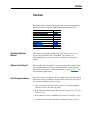
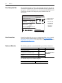
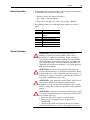
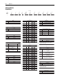
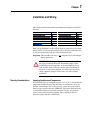
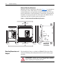
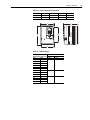
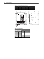
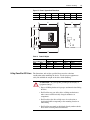
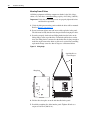
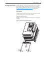
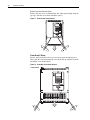
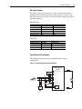
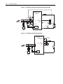
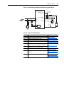
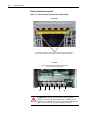
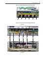
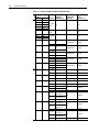
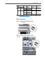
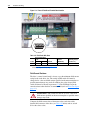
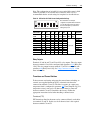
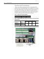
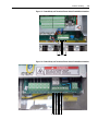
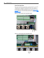
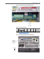
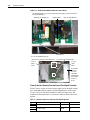
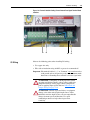
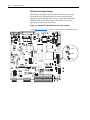
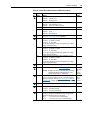
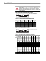
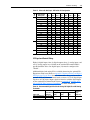
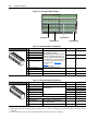
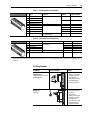
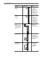
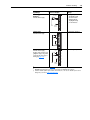
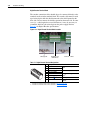
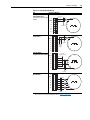
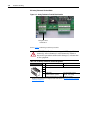
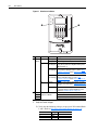
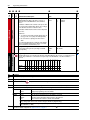
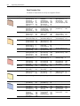
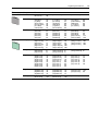
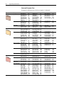
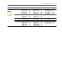
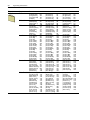
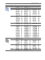
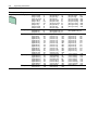
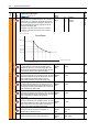
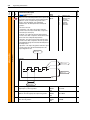
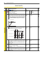
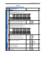
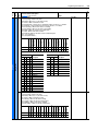
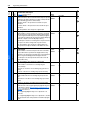
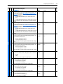
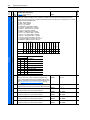
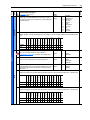
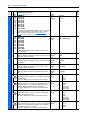
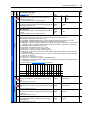
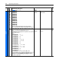
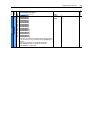
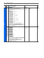
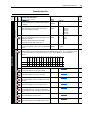
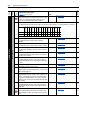
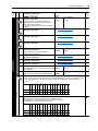
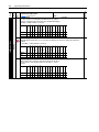
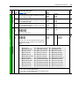
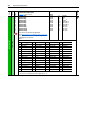
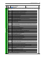
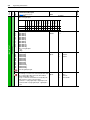
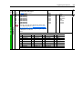
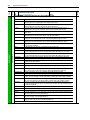
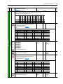
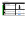
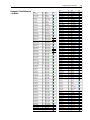
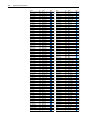
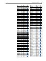
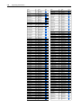
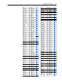
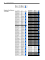
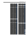
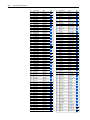
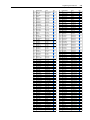
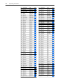
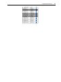

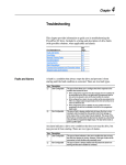


![[输入书名]](http://vs1.manualzilla.com/store/data/005783394_1-fc20c72617a19a0d7587a472ef1576a7-150x150.png)