1
DSCUSB Toolkit Manual
Strain Gauge or Load Cell Digitiser Module
User Manual
www.mantracourt.co.uk
Contents
Chapter 1 Introduction ................................................................................................................. 2
Overview................................................................................................................................ 2
Chapter 2 Getting Started ............................................................................................................. 3
Communications Interface Information .......................................................................................... 3
DSC Toolkit ............................................................................................................................. 3
What Can The Toolkit Do? ......................................................................................................... 3
Installing DSC Toolkit............................................................................................................... 3
Found New Hardware Wizard ..................................................................................................... 4
Connecting up the Device........................................................................................................... 6
Using the Software.................................................................................................................. 6
Chapter 3 Explanation of Filter......................................................................................................16
Dynamic Filtering, Filter Level & Filter Steps .................................................................................16
Chapter 4 Installation..................................................................................................................18
Before Installation ...................................................................................................................18
Identifying Strain Gauge Connections ...........................................................................................19
4-wire load cell..................................................................................................................... 19
6-wire load cell..................................................................................................................... 19
Chapter 4 Specifications ..............................................................................................................20
Technical Specifications DSCUSB .................................................................................................20
Environmental Approvals .............................................................................................................21
CE Approvals ........................................................................................................................ 21
Warranty..................................................................................................................................21
1
Mantracourt Electronics Limited DSCUSB User Manual
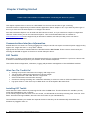
Chapter 1 Introduction
This chapter provides an introduction to the DSCUSB products, describing the product range and main features.
Overview
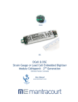
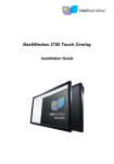
The DSCUSB products are high-precision Strain Gauge Converters; converting a strain gauge sensor input to a digital
USB serial output. They allow high precision measurements to be made and communicated directly to a PC. With the
appropriate drivers installed, the DSCUSB appears as a virtual communication port to the PC .
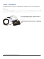
Free-standing module fitted with 9-way ‘D’ type socket for
load cell, temperature and digital I/O connections.
Integral USB lead with type ’A’ connector.
Dimensions:
Case: 86 x 57 x 26.5mm excluding connector (95mm (3.740”)
including 9-way ‘D’ type socket) with 136cm (4.462 feet) USB
cable.
Mantracourt Electronics Limited DSCUSB User Manual
2
Chapter 2 Getting Started
Please ensure that software is installed before connecting the device to your PC
This chapter explains how to connect to a DSCSUEASC for the first time and how to get it working.
The ASCII version is supported by a Toolkit software application that is simple to use. If you have any other type of
device you must use Instrument Explorer to configure the device.
Note that Instrument Explorer can be used with ASCII devices as well, so if you need more complex configuration
than DSC Toolkit offers you can use Instrument Explorer. This can be downloaded from our website at
www.mantracourt.co.uk and is supported by an alternative manual, DSC USB (517-180), which can also be
downloaded from our website
Communications Interface Information
DSCUSB devices can connect to a PC by plugging into a USB port and do not require an external power supply as they
appear as a ‘single unit load’ i.e. they draw <100mA.
Appropriate drivers must be installed which are bundled with the DSC Toolkit. These create a virtual serial port
allowing the DSCUSB to appear to the PC as a normal COM port device.
DSC Toolkit
DSC Toolkit is a simple configuration tool designed specifically for configuring ASCII DSCs. If you have a device with
a different communications protocol you will have to use Instrument Explorer.
This toolkit allows configuration, calibration, logging and parameter management of the DSCSUEASC modules.
What Can The Toolkit Do?
•
•
•
•
•
•
Viewing of input with enunciators for integrity and range errors.
Two point auto calibration by application of known weight.
Setting System Zero and under and over range limits.
Select measurement rate and filter settings.
Save device settings including user calibration and ability to restore to same or different USB DSC modules.
Log input value to a CSV file at up to 100Hz which can be analysed in Microsoft Excel.
Installing DSC Toolkit
Install the DSC Toolkit software by inserting the CD in the CD ROM drive. This should start the ‘AutoRun’ process,
unless this is disabled on your computer.
(If the install program does not start of its own accord, run SETUP.EXE on the CD by selecting ‘Run’ from the ‘Start
Menu’ and then entering D:\SETUP, where D is the drive letter of your CD-ROM drive).
The installation software pre-installs the required drivers so that they can be automatically found when the
hardware is plugged in later on.
3
Mantracourt Electronics Limited DSCUSB User Manual
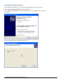
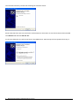
Found New Hardware Wizard
After installing the software you can connect the DSCUSB device to the computer.
The ‘Found New Hardware Wizard’ should now appear.
Select ‘No, not at this time’ so that the wizard does not try searching online for a driver.
Click ‘Next’.
Now the wizard will start searching for the drivers.
Mantracourt Electronics Limited DSCUSB User Manual
4
The wizard should then proceed with installing the software drivers.
Please note that there are two interfaces to the hardware so that there are two drivers that will be installed
The USB DSC Port and the USB DSC Bus.
So the next dialog box you will see will be for the USB DSC Port and the steps will be repeated from step 2.
5
Mantracourt Electronics Limited DSCUSB User Manual
Connecting up the Device
Simply connect to a spare USB port on the PC using the lead provided in the kit.
Using the Software
The DSC Toolkit automatically detects the connected DSCs so you do not need to worry about baudrates, station
numbers or COM port numbers.
If there is only one USB DSC connected when you launch the DSC Toolkit it will be automatically selected and the
Information Page will be displayed.
If multiple devices are detected you will be presented with a list to choose from on the Home Page.
To connect to a device just click on it in the list and click the ‘Connect’ button (Or just double click the device in
the list).
You will then see the Information page.
If no devices are detected the ‘Connect’ button changes to ‘Demo’. If you click the ‘Demo’ button you can navigate
through the software application with no device attached.
Mantracourt Electronics Limited DSCUSB User Manual
6
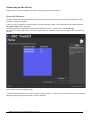
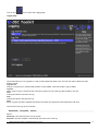
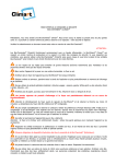
Information Page
This simply shows a large display and indicates if any error conditions are present by displaying an information box.
7
Mantracourt Electronics Limited DSCUSB User Manual
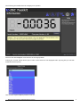
The following screenshot shows an Integrity error present.
The error box will disappear once the error is no longer present.
Clicking the ‘Format’ button allows you to select a new format for the displayed value. By using this you can hide
unwanted decimal places.
Just click the required display format in the list.
Mantracourt Electronics Limited DSCUSB User Manual
8
To select a different device just click the Home icon
Home Page
You can then select a different device or plug in a different device. If you change the connected devices click the
‘Detect’ button to re-list the devices. Then select the required device from the list.
9
Mantracourt Electronics Limited DSCUSB User Manual
Click on the
icon to open the Save & Restore page.
Save And Restore Page
Clicking the ‘Save’ buttons will allow you to specify a file to which the configuration of the connected device is
written.
Once saved this file can be selected, after clicking the ‘Restore’ button, and the settings restored to the same
device or to another device.
Mantracourt Electronics Limited DSCUSB User Manual
10
Click on the
icon to open the Data Rates & Filter page.
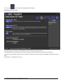
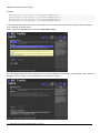
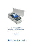
Data Rates And Filter Page
This page allows you to select the measurement rate and filtering characteristics.
The measurement rate affects the noise free resolution which is indicated at the bottom of the page.
The filter level and filter steps affect the frequency response of the input which is indicated at the bottom of the
page.
See Chapter 3 – Explanation of Filter
11
Mantracourt Electronics Limited DSCUSB User Manual
Click on the
icon to open the Calibration page.
Calibration Page
This page allows you to calibrate the device, set limits and perform system zero.
2 Point Auto Calibration
The automatic calibration requires that you apply two known (ascending) weight in sequence. Just enter the
required engineering unit value for the two weights in the fields marked 1 and 2.
Next, apply the low weight and allow a settle time. Click the ‘Acquire’ button then apply the high weight. After
another settle time click the second ‘Acquire’ button and the calibration is complete.
2 Point Certificate Calibration
This option lets you calibrate direct from the loadcell manufacturers certificate without having to apply weights to
the input.
Choose 2 points from the loadcell certificate and enter the mV/V values and the weights on the certificate (or
convert the certificate weight to any other engineering unit of your choice) click the ‘Calibrate’ button and the
calibration is complete.
System Zero
To remove the current weight on all subsequent readings click the ‘Zero’ button. Click the ‘Remove’ button to
return to displaying the actual weight applied. This system zero is stored in the device and remains through power
cycling.
Mantracourt Electronics Limited DSCUSB User Manual
12
Shunt Calibration
Click the ‘Turn On’ ‘Turn Off’ button to toggle the shunt calibration output. The shunt cal internally connects a
resistor across the strain gauge bridge. This can be used to quickly verify the gain settings of the device.
Over & Under-range Limits
Here you can set limits below and above which the warning indicators will be displayed on the Information Page.
13
Mantracourt Electronics Limited DSCUSB User Manual
Click on the
icon to open the Logging page.
Logging Page
The toolkit allows you to log data to a CSV (Comma Separated Value) file. This file will open in MS Excel when
double clicked.
Log Interval
Choose a Log Interval in milliseconds between 10 and 32000. 10mS will enable a log at 100Hz.
Log File
Select a file to log to. Note that each time the log starts it will erase any data already in the file.
Start
Clicking this button will start the log.
Stop
Clicking this button will stop the log.
View
When a log has just been stopped this button will launch the application associated with CSV files.
The format of the log file is as follows:
DateTime, Elapsed, Value
Where:
DateTime is the date and time in long format
Elapsed is the time elapsed in milliseconds since the start of the log
Mantracourt Electronics Limited DSCUSB User Manual
14
Value is the numeric value logged
Example
08/06/2009
08/06/2009
08/06/2009
08/06/2009
15:41:08,0,-3.25300008989871E-03
15:41:08,10,-3.25300008989871E-03
15:41:08,43,-3.25300008989871E-03
15:41:08,60,-3.25300008989871E-03
If the measurement rate of the device is less than the rate at which you have chosen to log you will be informed
with a message as shown below.
Either reduce the Log Interval or reduce the Measurement Rate.
Once the logging starts the actual achieved log rate will be displayed at the bottom of the window. This is useful for
diagnostics such as when a heavily burdened PC is slowing the log rate.
15
Mantracourt Electronics Limited DSCUSB User Manual
Chapter 3 Explanation of Filter
Dynamic Filtering, Filter Level & Filter Steps
The Dynamic filter is basically a recursive filter and therefore behaves like an ‘RC’ circuit. It has two user settings,
a level set in mV/V and the maximum number of steps (up to 255).
Instead of outputting every new value, a fraction of the difference between the new input value and the current
filtered value is added to the current filtered value to produce the filtering action.
If this difference is less than the value set in the Filter Level then the fractional amount added each time is
decremented until it reaches the minimum level set by FFST i.e. FFST is the limit of the divisor.
e.g. if Filter Steps = 10 the fractional part of the difference between the new value and the current filtered value
will be decremented as follows: 1/1, 1/2, 1/3, 1/4, 1/5, 1/6 . . . 1/10, 1/10, 1/10 before being added to the
current filtered value.
If a rapidly changing or step input occurs and the difference between the new input value and the current filtered
value is greater than the value set in Filter Level then the output of the filter will be made equal to the new input
reading i.e. the fractional amount of the new reading added to the current reading is reset to 1
This allows the Filter to respond rapidly to fast moving input signals.
When a step change occurs which does not exceed Filter Level, the new filtered value is calculated as follows:
New Filter Output value = Current Filter Output Value + ((Input Value - Current Filter Output Value) / Filter
Steps)
The time taken to reach 63% of a step change input (which is less than Filter Level) is the frequency at which values
are passed to the dynamic filter, set in Measurement Rate, multiplied by Filter Steps.
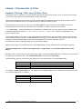
The table below gives an indication of the response to a step input which is less than Filter Level.
% Of Final Value
63%
99%
99.9%
Time To settle
Measurement Rate * Filter Steps
Measurement Rate * Filter Steps * 5
Measurement Rate * Filter Steps * 7
For example, If Measurement Rate is set to 100Hz = 0.01s and Filter Steps is set to 30 then the time taken to reach
a % of step change value is as follows.
% Of Final Value
63%
99%
99.9%
Time To settle
0.01 x 30 = 0.3 seconds
0.01 x 30 x 5 = 1.5 seconds
0.01 x 30 x 7 = 2.1 seconds
Mantracourt Electronics Limited DSCUSB User Manual
16
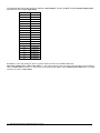
The following table shows the number of updates ‘x Filter StepsT’ and the ‘% Error’ that the Filtered Output value
will differ from the constant Input Value.
x FFST
% Error
1
36.78794412
2
13.53352832
3
4.97870684
4
1.83156389
5
0.67379470
6
0.24787522
7
0.09118820
8
0.03354626
9
0.01234098
10
0.00453999
11
0.00167017
12
0.00061442
13
0.00022603
14
0.00008315
15
0.00003059
16
0.00001125
17
0.00000414
18
0.00000152
19
0.00000056
20
0.00000021
Remember: if the step change in mV/V is greater than the value set in Filter Level then:
New Filter Output value = New Input Value i.e. the output jumps to the new input value and the internal working
value of Filter Steps is reset to 1. This is then incremented each update (set by Measurement Rate) until it reaches
the user set value of Filter Steps.
17
Mantracourt Electronics Limited DSCUSB User Manual
Chapter 4 Installation
This chapter gives detailed information on integrating the DSCUSB into a production system – including mounting,
protection, adjustments, wiring and electrical requirements.
Before Installation
Carefully remove the DSCUSB device from its shipment box. Check that the device is complete and undamaged.
Check the Product Type Code – on the product label is that which you ordered.
The DSCUSB can operate in any industrial environment providing the following limits are not exceeded
Operating Temperature
Humidity
Storage temperature
Mantracourt Electronics Limited DSCUSB User Manual
-40 ºC to +85 ºC
95% non condensing
-40 ºC to +85 ºC
18
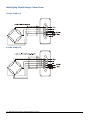
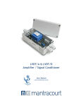
Identifying Strain Gauge Connections
4-wire load cell
6-wire load cell
19
Mantracourt Electronics Limited DSCUSB User Manual
Chapter 4 Specifications
Technical Specifications DSCUSB
The DSCUSB is factory set for 2.5mV/V sensitivity.
Parameter
Strain Gauge Excitation System
Strain Gauge Excitation Voltage
Strain Gauge Drive Capability
Strain Gauge Sensitivity
Offset Temperature Stability
Gain Temperature Stability
Offset Stability with Time
Gain Stability with Time
Min
Typical
4. 5
80
-3
5
2.5
5
30
35
Electrical
Power Supply voltage
Power Supply current (350 Ohm Bridge)
4.25
5
68
5.5
75
V dc
mA
Data transmission
Data transmission rate
Output cable length (speed dependant)
2.4
-
460.8
5
kbps
m
+85
+85
95
C
C
%RH
Non Linearity before Linearization
Internal Resolution
Resolution @ 1Hz readings (Noise stable) over 100s
Resolution @ 10Hz readings (Noise stable) over 100s
Resolution @ 100Hz readings (Noise stable) over 100s
Resolution @ 500Hz readings (Noise stable) over 100s
Signal Filter
Environmental
Operating temperature range
Storage temperature
Humidity
Dimensions
Cased version
Max
4 Wire
5.25
5000
3
10
50
160
300
Units
VDC
Ohms
mV/V
ppm/C
ppm/C
ppm of FR (1)
ppm of FR
(2)
5
25
ppm of FR
16 Million
Counts/divs
66,000
Counts/divs
40,000
Counts/divs
10,000
Counts/divs
5,000
Counts/divs
Dynamic recursive type user programmable
-40
-40
0
86 x 57 x 26.5mm (3.3465 x 2.2492 x
1.087”) excluding connector (95mm 3.740”)
including 9-way ‘D’ type connector) with 136 cm
94.462 feet USB cable.
Notes.
1. From original offset at any time
2. 1st Year
Mantracourt Electronics Limited DSCUSB User Manual
20
Environmental Approvals
CE Approvals
European EMC Directive
2004/108/EC
BS EN 61326-1:2006
BS EN 61326-2-3:2006
Output shall not exceed the sum of uncertainties when subjected to an electric field of 10V/m over the frequency
range 80 to 600MHz
Warranty
All DSC products from Mantracourt Electronics Ltd., ('Mantracourt') are warranted against defective material and workmanship for a period of
(3) three years from the date of dispatch.
If the 'Mantracourt' product you purchase appears to have a defect in material or workmanship or fails during normal use within the period,
please contact your Distributor, who will assist you in resolving the problem. If it is necessary to return the product to 'Mantracourt' please
include a note stating name, company, address, phone number and a detailed description of the problem. Also, please indicate if it is a
warranty repair.
The sender is responsible for shipping charges, freight insurance and proper packaging to prevent breakage in transit.
'Mantracourt' warranty does not apply to defects resulting from action of the buyer such as mishandling, improper interfacing, operation outside
of design limits, improper repair or unauthorised modification.
No other warranties are expressed or implied. 'Mantracourt' specifically disclaims any implied warranties of merchantability or fitness for a
specific purpose. The remedies outlined above are the buyer’s only remedies. 'Mantracourt' will not be liable for direct, indirect, special,
incidental or consequential damages whether based on the contract, tort or other legal theory.
Any corrective maintenance required after the warranty period should be performed by 'Mantracourt' approved personnel only.
ISO 9001
REGISTERED FIRM
C
In the interests of continued product development, Mantracourt Electronics Limited reserves the right to alter product specifications without prior notice.
DESIGNED & MANUFACTURED IN THE UK
Code No 517-916
21
Mantracourt Electronics Limited DSCUSB User Manual
Issue 1.3
26.07.11