1
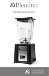
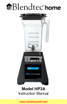
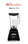
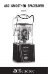
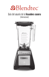
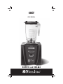
CHEF USER MANUAL 2 Table Of Contents Section Section 1.....Important Safeguards Section 2.....Component Overview Section 3.....Unpacking Section 4.....Installation Section 5.....Operating Instructions Section 6.....Warranty and Service Section 7.....Product Diagrams Page 5 7 8 9 11 16 19 3 SECTION 1: IMPORTANT SAFEGUARDS READ ALL INSTRUCTIONS CAREFULLY BEFORE USING YOUR BLENDTEC MACHINE. 1.1 SAFETY CERTIFICATION The Chef blender (ICB4) and accessories are certified by ETLto UL standard 763, and to CSA standard C22.2 No. 195-m1987, and to CE Standards. R 1.2 HEALTH CERTIFICATION The Chef blender and accessories are certified by NSF International. 1.3 AVOID CONTACT WITH MOVING PARTS Keep fingers, hands, hair and clothing away from all moving parts. Keep all utensils away from the drive socket and blender blades during operation. Metal utensils will damage blades. NEVER put hands into blender jar or add substances by hand when blender is operating. NEVER place jar into drive socket if blender motor is operating. Do not rock the blender when it is operating. Keep the blender jar straight up until the operation is complete. These precautions will prevent personal injury and/or damage to the blender. 1.4 POWER CORD PRECAUTIONS Do not operate with a damaged cord or plug. If the supply cord is damaged, it must be replaced by the manufacturer or its service agent in order to avoid a hazard. Do not let the cord hang over the edge of the work surface. Never use an extension cord with the unit. Unplug the blender motor before removing from sound enclosure, changing blender locations, or cleaning. 1.5 NEVER ATTEMPT TO REPAIR THE POWER UNIT Never remove the blender base cover. The blender base does not contain self-adjustable or serviceable parts. All service and adjustments must be made by a qualified service agent. Removing the cover or attempting to service the blender will void the warranty. 1.6 TURN THE UNIT OFF WHEN NOT IN USE 1.7 PROTECT EACH POWER UNIT WITH A SEPARATE CIRCUIT The 110/120 volt receptacle for each machine must be protected by a separate 20 AMP circuit breaker or fuse. The 220/240 volt receptacle for each power unit must be protected by a separate 10 AMP circuit breaker or fuse. 5 Do not use any other electrical equipment on the same circuit as the blender or you risk overloading the circuit and either damaging the blender electronics or blowing the circuit protection. 1.8 NEVER OPERATE IF THE UNIT APPEARS DAMAGED If the blender malfunctions call the service agent first. If it is dropped or damaged in any way, return the blender to a Blendtec service agent immediately for examination, repair, electrical or mechanical adjustment, or possible replacement. 1.9 NEVER OPERATE IN LIQUID Do not operate the blender motor in water or any other liquid. Avoid any contact between the motor and water. Deliberate use of machine outdoors in conditions where precipitation is present will void the warranty. 1.10 NEVER PUT ITEMS SUCH AS METAL, ROCKS, OR OTHER HARD MATERIALS INTO BLENDER JAR Metal utensils and other hard materials are dangerous. They can cause injury or damage. Damage caused by such foreign objects will void the warranty. 1.11 NEVER OPERATE USING ATTACHMENTS NOT SOLD BY BLENDTEC The use of unauthorized attachments voids the warranty and may cause fire, electric shock, or injury. 1.12 ALWAYS SECURE THE BLENDER LID BEFORE STARTING THE MACHINE Even if you have a sound enclosure, make sure you place a lid on the blender jar before you close the cover. 1.13 AVOID TOUCHING THE METAL BASE AFTER EXTENSIVE USE The metal base of the blender may become hot after numerous cycles. 1.14 BLADES ARE SHARP! HANDLE CAREFULLY 1.15 NEVER CLEAN THIS UNIT WITH A WATER JET. 1.16 THE POWER CORD RECEPTACLE WHICH POWERS THE BLENDER MUST ALWAYS BE ACCESSIBLE. 1.17 CIRCUIT BREAKER OR FUSE The 110/120 volt receptacle for each machine must be protected by a separate 20 AMP circuit breaker or fuse. SAVE THESE INSTRUCTIONS 6 SECTION 2: COMPONENT OVERVIEW 2.1 BLENDER MOTOR The blender motor consists of the blender base shell, touch pad control, Liquid Crystal Display (LCD) information center, and the power unit. (See Figures 1.1 and 1.2, pg. 19) Motor housing: Houses the power unit in a metal and stainless steel casing. Never remove the motor cover. Removal of the motor cover will void the warranty. Touch Pad: This contains the buttons which control the operation of the blender. LCD Information Center: When a cycle is completed, the display increments the cumulative cycle for warranty purposes. It also indicates overload or overtemperature conditions. Blender Motor: This unit is located within the motor housing and contains the machinery which runs the blender, including the electric motor, drive train, and computerized control board. 2.2 BLENDER JAR ASSEMBLY The blender jar assembly consists of the blender jar, blade assembly, and lid. The blender jar assembly integrates these components to ensure greater operator safety. Jar: Made to provide maximum performance as well as clear visibility of blender operations. Blade Assembly: Stainless steel, designed to ensure fast, consistent blending. Lid: Designed to enable the user to pour liquids or add other food items into the jar while blending, after removing the clear center cap and to provide venting for hot liquids. 2.3 OPTIONAL SOUND ENCLOSURE The sound enclosure reduces noise created during blender operation, when used with an optional gasket. 2.4 MOTOR BASE STAND A “top-of-the-counter” version of the blender is created by combining the sound enclosure described above with the motor base into which the blender motor is inserted. This allows for portable operation of the blender. 2.5 POWER SPECIFICATIONS Blendtec Blenders are made with power specifications listed below according to your specific model. 7 110/120 VOLT BLENDTEC BLENDERS ARE REQUIRED TO BE PROTECTED BY A DEDICATED 20 AMP CIRCUIT BREAKER OR FUSE. MODEL (110/120 VOLT) AMPS WATTS ICB4 (Chef Blender) 15 1800 220/240 VOLT BLENDTEC BLENDERS ARE REQUIRED TO BE PROTECTED BY A DEDICATED 10 AMP CIRCUIT BREAKER OR FUSE. MODEL (220/240 VOLT) AMPS WATTS ICB5 (Chef Blender) 9 2000 SECTION 3: UNPACKING SAVE THE TWO FOAM INSERTS AND ALL PACKAGING FOR FUTURE STORAGE OR SHIPPING. SAVE THESE INSTRUCTIONS FOR FUTURE REFERENCE. 3.1 UNPACKING YOUR BLENDER 1. You should have received the following items: Chef Blender Base ICB4 Motor Base (International models have the ICB5 Motor Base) Blender Jars (2 each) with Lids (2 each) Sound Enclosure (optional) Additional Blender Jars (optional) 2. Remove blender motor, blender jars and lids from carton. 3. Unwind the power cord. 4. Check for and remove any packing material which may have blocked ventilation holes in either the power unit or the black motor stand. 5. Inspect all items to ensure no damage occurred in shipment. 6. If any damage has occurred contact your Blendtec service agent immediately. 8 3.2 RECORDING YOUR SERIAL NUMBER AND DATE OF SHIPMENT Record your blender base serial number and date of purchase in the space below. You will need these when contacting Blendtec for service. Blender Serial No. ____________________________________ Date of Purchase ___________________________________ Refer to these whenever contacting your Blendtec service agent. SECTION 4: INSTALLATION 4.1 Above Counter Installation 1. Ensure that an electrical receptacle is readily accessible where you locate the equipment. 2. When you receive your Chef blender, the motor base will ship inside the motor base stand. Please make sure the unit is switched off before assembling. 3. To use the unit in an above counter application, make sure once the motor base is in place that the rubber gasket fits smooth and tight. (If you also have the optional sound enclosure, first remove the top lid of the sound enclosure and set it aside, then remove the motor base from the motor base stand and set the sound enclosure on top of the motor base stand. Place the motor base back into the motor base stand and make sure the rubber gasket is smooth and tight, then replace the top lid on the sound enclosure. 4. Make sure the touch pad is facing the front of the stand and extend the cord out of the bottom of the stand to its full length. 5. Set the equipment on the counter and plug it into the available dedicated electrical outlet with adequate protection per local electrical codes. 6. Ensure clearance above the counter around the installation to allow for unhampered operation of the sound enclosure. 7. When using the optional sound enclosure, a different gasket is required so the motor base will line up properly in the motor base stand. If you do not have the optional gasket one may be obtained by calling your local dealer or Blendtec customer service. 9 4.2 Preparation for In-Counter Installations 1. Identify desired blender location. Consider preferences such as proximity to ingredients, proximity to customers, available counter space, and available electric outlets. 2. Ensure potential site meets all dimensional requirements. (See Figures 3.1-3.3.) Counter top can be no thicker than 3/4 in (19 mm). A counter top thicker than 3/4 in. (19 mm) will obstruct ventilation louvers on the upper sides of the motor. If installing more than one blender, allow 14 to 16 in. (356 - 406 mm) center-tocenter blender spacing. If installing a sound enclosure, allow a clearance of at least 8-1/2 in. (216 mm) from the sound enclosure to the wall and 26 in. (660 mm) from the counter top to any over-the-counter cabinetry. Ensure lower cabinetry allows adequate airflow. There should be at least 8-1/8 in. (205 mm) from the counter top to the next lower shelf of the cabinet, leaving a minimum space of 3 in. (76 mm) between the bottom of the motor and the lower shelf. Cabinetry should not be closed, but should allow free flow of air from outside to inside cabinet space. NOTE: The blender unit draws ambient air into the louvers located on the bottom of the motor. It then evacuates hot air through the louvers located on the upper sides of the motor. Ensure a sufficient amount of air circulates beneath the motor to allow cooling. Hot air should not be trapped beneath the counter top. Plastic bags, cups, etc. should not be stored closer than 3 inches (76mm) from the bottom of the motor. 3. Cut a hole in the counter top 4-3/8 in. (111 mm) wide and 5-7/8 in. (149 mm) long with the shorter side facing the operator (See Figure 4). Make sure all space requirements and measurements are correct BEFORE cutting. 4.3 In-Counter Installation 1. Ensure that an electrical receptacle is readily accessible when you locate the equipment. 2. If your unit came with the optional sound enclosure, first remove the sound enclosure lid (top). Place the clear sound enclosure bottom on the counter making sure the hole in the of the sound enclosure is aligned with the hole in the counter top. If you don’t have a sound enclosure you can skip this step. 10 3. Thread the power cord through the base of the sound enclosure and the counter top hole being careful not to scratch or damage the enclosure. 4. Gently place the motor base into the sound enclosure and slide it into the hole in the counter top. Make sure the LCD indicator and touch pad are facing the operator’s side of the counter. Also ensure that the rubber gasket on the motor fits snugly and evenly into the sound enclosure and counter top holes. (If you do not have a sound enclosure the motor base simply fits into the hole in the counter top. 5. Re-install the sound enclosure lid. 6. Plug the unit into a receptacle with a dedicated circuit and appropriate protection. Make sure power switch is turned off before plugging unit in. SECTION 5: OPERATING INSTRUCTIONS 5.1 OPERATIONAL OVERVIEW 1. If blender is not turned on, turn on the main power switch located on the front of the blender motor. 2. Place the properly filled blender jar on the motor, making sure the jar is seated all the way down and jar lid is secured tightly on the jar. 3. Press the desired button on the touchpad. 5.2 MANUAL OPERATION This machine is equipped with button activated electronic speed controls. Motor speed and run time are indicated on the LCD display. Speed 1 is the lowest speed, and speed 20 is the highest. On the right hand side of the touchpad are an UP and DOWN button. Pressing the UP button once will start the motor at speed four. Pressing the down button will start the motor at speed 1. Holding the speed up/down buttons down will cause the motor speed to ramp up or down. Pressing and releasing these buttons will cause the motor to speed up or down by one speed level. When the blender is started using the up/down buttons, the count down timer is set for 60 seconds. Additional time (up to a total of 90 seconds) can be added at any time during the cycle using the +5 SEC TIME SELECT button, and the blender can be stopped at any point using the STOP button. The blender can also be started at speed 4 by pressing the + 5 SEC TIME SELECT button Pressing the LOW PULSE button will run the motor at speed 9 until the button is released. 11 Pressing the HIGH PULSE button will run the motor at speed 17 until the button is released. 5.3 AUTOMATIC CYCLE OPERATION Your Chef machine is designed to record, store, and replay manual operations up to 90 seconds long. This allows you to easily create custom blend cycles which are best suited to blending specific recipes and need to be used repeatedly. To use this feature, simply run the blender manually using the speed up/down buttons, then press and hold down the MEMORY 1 MEMORY 2 or MEMORY 3 button. The blender will beep twice and the LCD display will display “Storing to Mem _(1,2 or 3)”, indicating that the self-made blend cycle is being stored to that button. Once the LCD display returns to the standard “Blendtec” screen the blend cycle has been stored and can be played back by pressing that memory button. To delete the cycle stored in MEMORY, simply store another manual cycle in that memory button and it automatically deletes the one which was previously stored. 5.4 TROUBLE SHOOTING SUGGESTIONS Error Message on the LCD screen: The “OVERTEMP” error message indicates an overheated condition has been detected and the motor has been disabled until the unit cools to operating temperatures. Unplug the motor and allow cooling for at least 20 minutes. The “OVERLOAD” error message indicates too heavy of a load on the motor. This is usually caused by a blockage in the jar preventing the blender blades from turning. The overload error is cleared by turning off the blender for ten seconds (using the switch), then turning back on. Remove the jar from the blender to clear any blockage, then use the LOW PULSE button on the touch pad to quickly pulse the blade through the mixture. Once the blade spins freely a programmed button may be used. If blender fails to start after following these steps, contact your Blendtec service center for assistance. A “WATCHDOG TIMEOUT” error indicates a disruption in the normal operation of the electronic blender controls. This is an uncommon error message, which is usually caused by incoming power fluctuations or spikes. This error message is cleared by turning off the blender for ten seconds (using the switch), then turning back on. If this error is displayed immediately on start-up, or if it occurs regularly during normal use contact your Blendtec service center for assistance. BLENDER MOTOR WILL NOT TURN ON. If the blender motor will not turn on, try the following: Check to make sure that the blender is plugged in. Check to make sure that the power switch is turned on. Check to see if there are any messages on the LCD display. Absence of a lighted LCD display indicates that there is a lack of power to the microprocessor. Check the house current breaker switch or fuse to make sure that it is set to the on position. If none of the above addressed the problem, contact your Blendtec service center for assistance. BLADE STOPS: If the overload switch stops the blender, remove the blender jar and carefully check for blockage of the blade. If no blockage is found, replace jar and 12 use the “Low Pulse” button on the touch pad to quickly pulse the blade through the mixture. Once the blade spins freely, a programmed button may be used. NOISE LEVEL CHANGES: If the blender noise level has increased significantly from original levels, determine whether the sound is coming from the motor or jar. Motor: Check to see if the excess noise is coming from the motor. Remove the jar from the base and press any button that starts the motor. Listen to the motor sound without a jar attached. If it is excessively noisy, contact your Blendtec service center. Jar: Check to see if the excess noise is coming from the jar. Place the jar back on the base. Run the motor for a few seconds using the “Low Pulse” button. Switch jars back and forth to determine whether the sound changes as different jars are used. If a jar is excessively noisy, or if the blade assembly seems loose or sounds “gravelly” when turned by hand, contact your Blendtec service center for assistance. BLENDED TEXTURE UNSATISFACTORY: If the blended texture of product is lumpy or uneven, do the following: Make sure the mixture is not cavitating during the cycle. Cavitation is a condition in which the blender blade spins freely in an air pocket within the drink mix because the mix is too cold or too solid. This problem can be corrected by increasing the mix temperature (by reducing ice, increasing liquid and/or ensuring that the frozen ingredients used in the recipe are never colder than 10 degrees Fahrenheit or -12 degrees Celsius). When the right combination of correctly tempered ingredients is used, the resulting drink is always smooth, thick and blendable without operator attention. Increase cycle time. If the food is mixing well but has not had enough time for complete blending, try more blend time or touch and hold the “Pulse” button for 13 required extra blending time. · Make sure the drive shaft on the jar is fully engaged into the drive socket or that the blade is firmly affixed to the drive shaft. TRIED EVERYTHING? If none of the preceding suggestions work, contact your Blendtec service agent for further assistance. 5.5 CLEAN BLENDER JAR DAILY 1. Using hot tap water, add 2 cups (1liter) of water and 1 to 2 teaspoons (7 ml) of liquid dish washing soap to the blender jar. 2. Place the lid tightly onto the jar. Place the blender jar on the motor and press the “Low Pulse” button for 15 seconds. 3. Rinse with clear water until all soap is rinsed from jar and lid. 4. Store the jar upside down wherever possible. When jars are stored upside down, ensure that no water is allowed to stand in the bottom around the blade drive shaft. 5. Two quart jars may be stacked one inside the other. Three quart jars can also be stacked by interlocking handles. NOTE: When washing the blender jar in a dishwasher, the jar should be placed on the top rack. Blender jars are dishwasher safe up to 220 degrees Fahrenheit (104 degrees Celsius). 5.6 SANITIZATION OF JAR 1. Periodically fill the blender jar with hot tap water. 2. Add 1 teaspoon (5 ml) of liquid chlorine bleach. 3. Stir for 10 seconds to mix water and bleach. Let mixture stand in blender jar for 5 minutes. 4. Empty water/bleach mixture. Store jar as described in section 5.5. 5.7 DAILY CLEANING OF MOTOR 1. Make sure the main power switch is off and motor is unplugged before cleaning. 2. Remove motor from sound enclosure. Remove the rubber gasket from the rim of the steel base and wash the gasket with a mild detergent. 3. When necessary, wipe the metal top and sides of the blender motor clean with a damp rag. Mild cleaners like WINDEX may be used. 14 5.8 WEEKLY CLEANING OF MOTOR (Done in addition to daily cleaning while motor is unplugged and removed from enclosure) 1. Fill the blender drive socket (see figure 1.2) with a strong cleaning solution such as 409 or Simple Green. DO NOT OVERFILL. Overfilling will cause damage to the motor. Let stand for 5 minutes. 2. Clean the inside ridges and grooves of drive socket with a toothpick, an ice pick or some other hard, pointed tool. 3. Turn the motor upside down to drain the material from the drive socket. Use a paper towel or rag to dry the area and replace the motor. 5.9 CLEANING TIPS AND CAUTIONS Do not use abrasives to clean the blender motor, jar, or sound enclosure as this will dull or scratch the surface Do not use a water jet of any kind to clean this equipment. NEVER submerge the blender motor in water - THIS WILL VOID THE WARRANTY Avoid submerging the blender jars for more than 5 minutes. Water penetration through the lower jar seals will reduce the jar life. When you have cleaned the jar, store it upside down. Do NOT allow water to stand in the lower seal area. · For long term storage of jar, apply a small amount of food-grade oil (such as vegetable oil) to the seals around the blade assembly both inside and outside of the blender jar. 15 SECTION 6: WARRANTY AND SERVICE 6.1 WARRANTY DESCRIPTION MOTOR: Standard Blendtec United States (US) warranties are as follows: Chef Blender 2 years or 15,000 cycles Standard Blendtec International (outside US) warranties are as follows: Chef Blender 2 years parts, 1 year labor JAR: The jar and internal bearing assembly are warrantied against failure as follows: Jar Model Warranty 40-501, 40-502, 40-503 180 days from purchase date 40-505, 40-508 1 year from purchase date The jar model number can be found under the NSF logo on the jar. BLADES: The stainless steel blade is warrantied against breakage for the life of the jar. Please note that dulling of the blade may occur as a result of usage and does not affect blending effectiveness. SOUND ENCLOSURE: The sound enclosure is warrantied for 90 days against manufacturing defects. DRIVE SOCKET: The drive socket (see Fig. 1.2) is warrantied for the life of the machine. Warranties begin from date of shipment, or on date of purchase where proof of purchase is provided. Cosmetic damage and abuse are not included within this warranty. 6.2 SERVICE PROCEDURE Should you experience any difficulty in using your Blendtec blender, please do the following: UNDER WARRANTY 16 1. Contact your authorized Blendtec service agent immediately to diagnose the difficulty. Please have your serial number ready as well as a description of the problem. Do not attempt to do your own repairs. Repairs made by persons other than Blendtec authorized service representatives will void the warranty. Many issues can be resolved simply and quickly over the phone. 2. If the difficulty cannot be resolved over the phone, your unit may require replacement. If you are under warranty, Blendtec will repair or replace your unit at no cost. Cosmetic damage and abuse are not included. OUT OF WARRANTY 1. Contact your Blendtec service agent to diagnose the difficulty. Please have your serial number ready along with a description of the problem. Many issues can be resolved simply and quickly over the phone. 2. If you are not under warranty and wish to have your unit repaired, box up your existing unit and ship the unit to your authorized Blendtec service agent. Your Blendtec service agent will bill you for services rendered. When shipping your blender unit to the service agent (either in warranty or out of warranty), Please include the following: Name: Company: Store Number: Address: Phone: Serial Number: (Found on the underside of the motor) Cycle Count: (Number on the LCD Screen) Purchase Date: Place of Purchase: Problem Description: 17 18 SECTION 7 - PRODUCT DIAGRAMS FIGURE 1.1 - FRONT VIEW: BLENDER MOTOR AND JAR Lid Jar Blade Assembly LCD Screen Power Switch FIGURE 1.2 - TOP VIEW: MOTOR Drive Socket Touchpad 19 20 9.35” (237.49 mm) SIDE VIEW 9.29” (235.96 mm) FRONT VIEW 18,41” (467.62 mm) 18.41” (467.62 mm) (65.78 mm) 2.59” SIDE VIEW (OPEN ENCLOSURE) 9.35” (237.49 mm) 22.51” (571.75 mm) FIGURE 1 - ON COUNTER - CHEF BLENDER (Shown with optional enclosure) 8.97” (227.8 mm) SIDE VIEW 8.49” (215.6 mm) FRONT VIEW 10.24” (260 mm) 10.24” (260 mm) SIDE VIEW (OPEN ENCLOSURE) 8.00” (203.2 mm) 14.37” (365 mm) FIGURE 2 - IN COUNTER - CHEF BLENDER (Shown with optional enclosure) 3.03” (77 mm) 21 FIGURE 4 - Countertop Hole Template 5-7/8” (149.22 mm) 4-3/8” (111.125 mm) 22 23 1206 South 1680 West Orem, UT 84058 801-222-0888 www. blendtec.com OWN-CE-033 Manual Chef Blender Rev 02 July 09