1
IDM UID
3VVU9W
VERSION CREATED ON / VERSION / STATUS
15 Apr 2013 / 4.6/ Approved
EXTERNAL REFERENCE
IT Technical Specifications
Plant system I&C Integration plan
This document describes the testing approach and methods and the organizational schemefor
planning and performing the FAT and SAT for any ITER I&C system.
Author
Co-Authors
Reviewers
Approver
Read Access
Name
Journeaux J.- Y.
Approval Process
Action
15-Apr-2013:signed
Affiliation
IO/DG/DIP/CHD/CSD/PCI
Wallander A.
Yonekawa I.
Thomas P.
18-Apr-2013:recommended
IO/DG/DIP/CHD/CSD
15-Apr-2013:recommended
IO/DG/DIP/CHD/CSD/PCI
30-Apr-2013:approved
IO/DG/DIP/CHD
Document Security: level 1 (IO unclassified)
RO: Journeaux Jean-Yves
AD: ITER, AD: External Collaborators, AD: Division - Control System Division - EXT, AD: Section CODAC - EXT, AD: Section - CODAC, AD: Auditors, project administrator, RO, LG: CODAC team
PDF generated on 30-Apr-2013
DISCLAIMER : UNCONTROLLED WHEN PRINTED – PLEASE CHECK THE STATUS OF THE DOCUMENT IN IDM
Title (Uid)
Plant system I&C
Integration plan
(3VVU9W_v4_6)
Plant system I&C
Integration plan
(3VVU9W_v4_5)
Plant system I&C
Integration plan
(3VVU9W_v4_4)
Plant system I&C
Integration plan
(3VVU9W_v4_3)
Plant system I&C
Integration plan
(3VVU9W_v4_2)
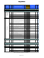
Latest Status
Change Log
Issue Date
Versio
n
v4.6
Description of Change
Approved
15 Apr
2013
Similar version as for v4.3, a foramt issue fixed
v4.5
Signed
15 Apr
2013
same as v4.2 plus format issues fixed
v4.4
Signed
15 Apr
2013
Introduction of the plant system I&C - central I&C
interface tests in IO CSD lab
v4.3
Approved
17 Jan
2013
v4.2
Approved
08 Jan
2013
Version reviewed for quality. Technical content is
not changed with respect to 4.2
Version issued in scope of PCDH v7
Satellite document of PCDH. Version released in
scope of PCDh v7. Two format issues fixed / v4.0
if(typeof editorarray == 'object')
{
Plant system I&C
Integration plan
(3VVU9W_v4_1)
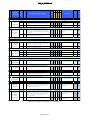
v4.1
Signed
08 Jan
2013
editorarray.push('TabPlaceHolder_DocumentView
1_ctl01_ctl00_ctl00_ctl16_ver_description')
}
Satellite document of PCDH. Version released in
scope of PCDh v7.
if(typeof editorarray == 'object')
{
editorarray.push('TabPlaceHolder_DocumentView
1_ctl01_ctl00_ctl00_ctl16_ver_description')
}
One format issue fixed / v4.0
Satellite document of PCDH. Version released in
scope of PCDh v7.
Plant system I&C
Integration plan
(3VVU9W_v4_0)
Plant system I&C
Integration plan
(3VVU9W_v3_0)
v4.0
Signed
08 Jan
2013
v3.0
Signed
12 Oct
2012
Plant system I&C
Integration plan
(3VVU9W_v2_5)
Plant system I&C
Integration plan
(3VVU9W_v2_4)
Plant system I&C
Integration plan
(3VVU9W_v2_3)
Plant system I&C
Integration plan
(3VVU9W_v2_2)
Plant system I&C
Integration plan
(3VVU9W_v2_1)
Plant system I&C
Integration plan
(3VVU9W_v2_0)
Plant system I&C
Integration plan
(3VVU9W_v1_5)
Plant system I&C
Integration plan
(3VVU9W_v1_4)
Plant system I&C
v2.5
Signed
26 Apr
2012
v2.4
Signed
18 Apr
2012
Minor changes
v2.3
Signed
17 Apr
2012
Version issued after Anders and Izuru review
v2.2
Signed
04 Apr
2012
v2.1
Signed
14 Sep
2011
Version completed by JY and requiring now the
veview/completion of stakeholders mentionned in
the text.
Intermediate version used in scope of CWS I&C
meeting on 14th of September
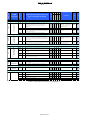
v2.0
In Work
08 Jul 2011
v1.5
Approved
09 Feb
2011
v1.4
Signed
09 Feb
2011
Updated following JYJ comments stored in IDM
with version 1.3
v1.3
Signed
09 Feb
Version after PCDH v6 external review
A number of improvement in wording,
simplification. section 2.5 added, campaign for
SDD merged to SW campaign. Scenario reduced
by pushing most of the requirement check at
design and manufacture phase
Some improvement for SAT scenario
Still in work, changes for simplification plus
alignment with PCDH v6.1, still interlock and
safety areas to complete and review.
Version issued after PCDH v6 external review
PDF generated on 30-Apr-2013
DISCLAIMER : UNCONTROLLED WHEN PRINTED – PLEASE CHECK THE STATUS OF THE DOCUMENT IN IDM
Integration plan
(3VVU9W_v1_3)
Plant system I&C
Integration plan
(3VVU9W_v1_2)
Plant system I&C
Integration plan
(3VVU9W_v1_1)
Plant system I&C
Integration plan
(3VVU9W_v1_0)
2011
v1.2
Signed
06 Jan
2011
Update of version number, ready for PCDH v6
review, JP comments included
v1.1
Signed
06 Jan
2011
THIS VERSION IS UPLOADED FOR PCDH v6
DOCUMENTATION PACKAGE
REVIEW ONLY!
v1.0
Signed
29 Nov
2010
PDF generated on 30-Apr-2013
DISCLAIMER : UNCONTROLLED WHEN PRINTED – PLEASE CHECK THE STATUS OF THE DOCUMENT IN IDM
Document Revision History
Version
1.0
1.1
Status
Draft
Draft
Date
19/08/2010
30/08/2010
1.2
1.3
Draft
1st
official
Version
17/09/2010
08/10/2010
1.4
Updated
16/11/2010
1.5
2.0
Updated
Updated
15/12/2010
15/04/2011
2.1
In work
15/10/2011
2.2
In work
04/04/2012
3.0
In work
27/09/2012
4.0
4.3
4.4
4.5
In work
Final
Final
Final
12/12/2012
17/01/2012
23/01/2013
12/03/2013
Changes
Initial version issued in scope an engineering support contract
Enhancements, including outcomes of 23rd of August review
with JY Journeaux in Cadarache
Draft issued for 2nd review by CSD team
Updates as per:
Antonio Fernandez and Izuru Yonekawa review forms
Outcomes of 24th of Sept review meeting in Cadarache
Updated following JYJ comments stored in IDM with version
1.3
Removed Pulse scheduling interface
After this date the versions have been issued directly by IO. JYJ
changes for simplification plus alignment with PCDH v6.1, still
interlock and safety areas to complete and review.
Completion of chapter 4, still the inputs from Denis, Bruno,
Nadine, Petri, Hitesh, Antonio, Jean-Marc to incorporate.
Scope enlarged to PS I&C integration, alignment with CODAC
DDD for the integration scheme.
A number of improvements in wording plus section 2.5 added,
C2 merged with C4. Campaign scenarios simplified.
Version submitted to J Poole review
Version issued in scope of PCDH v7
Introduction of SDD tests in chapter 3
Introduction of interface tests in chapter 3
Table of Contents
1
2
3
4
5
6
7
8
9
Introduction...........................................................................................................................3
1.1
Document purpose ......................................................................................................3
1.2
Acronyms .....................................................................................................................4
1.3
Conventions .................................................................................................................5
1.4
Reference documents ..................................................................................................5
The model of integration of I&C systems .............................................................................7
2.1
The Plant System I&C life-cycle................................................................................7
2.2
Plant system I&C integration model.........................................................................7
2.3
I&C system configuration types for the procurements ...........................................8
2.4
I&C actors for FAT and SAT ....................................................................................8
2.5
I&C deliverables and rules to be considered throughout the plant system I&C
life-cycle ...................................................................................................................................9
Details of the FAT for I&C systems....................................................................................10
3.1
FAT objectives for I&C and entering FAT ............................................................10
3.2
Scope of FAT for I&C systems ................................................................................10
3.3
Performing FAT for I&C systems...........................................................................10
Details of the assembly of procured equipment for I&C systems.......................................11
Details of SAT for I&C systems ..........................................................................................12
5.1
SAT objectives for I&C ............................................................................................12
5.2
Scope of SAT for plant system I&C ........................................................................12
5.3
Performing SAT for plant system I&C...................................................................12
I&C Acceptance Principles.................................................................................................14
6.1
Issue management.....................................................................................................14
6.2
Acceptance process ...................................................................................................14
6.3
Acceptance criteria ...................................................................................................15
Campaign details for FAT and SAT....................................................................................16
7.1
The PCDH requirement mapping matrix...............................................................16
7.2
Rules applicable to all campaigns............................................................................17
7.3
Campaign C1: I&C documentation ........................................................................18
7.4
Campaign C2: I&C hardware .................................................................................21
7.5
Campaign C3: configuration data and software....................................................23
7.6
Campaign C4: I&C functional requirements.........................................................25
PCDH rules not considered during FAT and SAT..............................................................27
PCDH requirements mapping matrix .................................................................................36
Page 2 of 35
1 Introduction
1.1 Document purpose
This document, part of the Plant Control Design Handbook (PCDH) satellite documents package, is a
handbook for specifying the procedures for the Factory Acceptance Tests (FAT) and Site Acceptance Tests
(SAT) for plant I&C systems.
Chapter 2 describes the integration model for I&C systems, chapter 3 provides details for the FAT, chapter
4 is dedicated to I&C assembly, chapter 5 provides details for the SAT, chapter 6 proposes acceptance
criteria but these must be aligned with the IO criteria when they are available, chapter 7 provides technical
details for the test procedures, chapter 8 list the requirements to be checked at design and manufacture
phase and chapter 9 provide the complete PCDH requirement mapping matrix for FAT and SAT.
PCDH comprises a core document which presents the plant system I&C life cycle and recaps the main
rules to be applied to the plant system I&Cs for conventional controls, interlocks and safety controls.
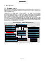
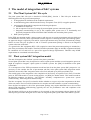
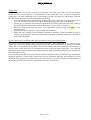
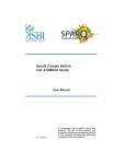
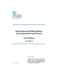
Some I&C topics are explained in greater detail in dedicated documents associated with PCDH. These are
presented in Figure 1-1 and this document is one of them.
PCDH core and satellite documents: v7
INTERLOCK CONTROLS
Guidelines for the design of the PIS (3PZ2D2)
PIS, PS I&C and CIS integration
Guidelines for PIS configuration
Management of local interlock functions
Management of interlock data
PS CONTROL DESIGN
Plant system I&C architecture (32GEBH)
Methodology for PS I&C specifications (353AZY)
CODAC Core System Overview (34SDZ5)
I&C CONVENTIONS
I&C Signal and variable naming (2UT8SH)
ITER CODAC Glossary (34QECT)
ITER CODAC Acronym list (2LT73V)
OCCUPATIONAL SAFETY CONTROLS
Rules and guidelines for PSS design
Core PCDH (27LH2V)
Plant system control philosophy
Plant system control Life Cycle
Plant system control specifications
CODAC interface specifications
Interlock I&C specification
Safety I&C specification
NUCLEAR PCDH (2YNEFU)
CATALOGUES for PS CONTROL
Slow controllers products (333J33)
Fast controller products (345X28)
Cubicle products (35LXVZ)
PS I&C integration kit
PS CONTROL DEVELOPMENT
I&C signal interface (3299VT)
PLC software engineering handbook (3QPL4H)
Guidelines for fast controllers (333K4C)
CODAC software development environment (2NRS2K)
Guidelines for I&C cubicle configurations (4H5DW6)
PS SELF DESCRIPTION DATA
Self description schema documentation (34QXCP)
PS CONTROL INTEGRATION
The CODAC -PS Interface (34V362)
PS I&C integration plan (3VVU9W)
ITER alarm system management (3WCD7T)
ITER operator user interface (3XLESZ)
Guidelines for archiving
Specifications for HPN
Specifications for time stamping
Guidelines for Diagnostic data
TEMPLATES and ILLUSTRATIONS
CWS case study specifications (35W299)
Cubicle illustrations
Figure 1-1: PCDH document package
Page 3 of 35
Legend
This document
Available and approved
Expected
(XXXXXX) IDM ref.
1.2 Acronyms
AI
Analogue Input
AO
Analogue Output
CENTRAL I&C Addition of PBS45, 46 and 48
CIN
Central Interlock Network
CIS
Central Interlock System
CODAC
COntrol Data Access and Communications
COS
Common Operating State
COTS
Commercial Off The Shelf
CPU
Central Processing Unit
CSN
Central Safety Networks
CSD
Control System Division of IO
DA
Domestic Agency
DI
Digital Input
DO
Digital Output
EMC
Electro-Magnetic Compatibility
EPICS
Experimental Physics and Industrial Control System
FAT
Factory Acceptance Test
HPN
High Performance Networks
HW
Hardware equipment or part
I&C
Instrumentation & Control
I&C SU
I&C Supplier
IEC
International Electro-technical Commission
I/O
Input / Output
IO
ITER Organization
NTP
Network Time Protocol
PA
Procurement Arrangement
PCIe
Peripheral Component Interconnect express
PIS
Plant Interlock System
PCDH
Plant Control Design Handbook
PLC
Programmable Logic Controller
PON
Plant Operation Network
PS
Plant System
PSOS
Plant System Operating State
Page 4 of 35
PSH
Plant System Host
PSS
Plant Safety System
PSE
Plant System Equipment
PS I&C RO
Plant System I&C Responsible Officer
PV
Process Variable
RIO
Remote IO chassis
RO
Responsible Officer
SDN
Synchronous Data-bus Network
SDD
Self-Description Data
SIL
Safety Integrity Level
SSEN
Steady State Electrical Network
SW
Software package
TBC
To Be Confirmed
TBD
To Be Defined
TCN
Time Communication Network
1.3 Conventions
Throughout this document mandatory rules (or requirements) are enumerated and prefixed with R. Non
mandatory guidelines (or recommendations) are enumerated and prefixed with G. The table below provides
a list of paragraph identifiers used in this document.
AD
Applicable Document
D
Deliverable for a lifecycle phase
G
Guideline / Recommendation
R
Rule / Requirement
RD
Reference Document
SD
Satellite Document
Paragraphs marked with TBD or TBC represent work in progress which will be confirmed and expanded
further in subsequent releases of this document.
1.4 Reference documents
The following documents are cited in this document:
[RD1]
Plant Control Design Handbook (27LH2V)
[RD2]
IO cabling rules, (335VF9)
[RD3]
ITER On-Site Testing Strategy (44U2Y4)
[RD4] ITER Policy on EEE in Tokamak Complex (6ZX6S3)
[SD1]
Plant System I&C Architecture (32GEBH)
[SD2]
Methodology for PS I&C specifications (353AZY)
[SD3]
I&C signal and variable naming convention (2UT8SH)
[SD4]
Self description schema documentation (34QXCP)
[SD5]
The CODAC - Plant System Interface (34V362)
Page 5 of 35
[SD6]
[SD7]
[SD8]
[SD9]
[SD10]
[SD11]
[SD12]
[SD13]
[SD14]
[SD15]
[SD16]
[SD17]
[SD18]
[SD19]
[SD20]
[SD21]
[SD22]
[SD23]
[SD24]
PS I&C integration plan (this document) (3VVU9W)
ITER operator user interface (3XLESZ)
ITER alarm system management (3WCD7T)
I&C signal interface (3299VT),
PLC software engineering handbook (3QPL4H)
Software engineering and QA (2NRS2K)
Slow Controller catalogue (333J63)
Guidelines for fast controllers (333K4C)
Fast Controller products catalogue (345X28)
Cubicle products catalogue (35LXVZ)
Guidelines for the design of the PIS (3PZ2D2)
CWS case study specifications (35W299)
ITER CODAC glossary (34QECT)
ITER CODAC Acronym list (2LT73V)
CODAC Core System Overview (34SDZ5)
Plant Control Design Handbook for Nuclear control systems (2YNEFU)
Management of local interlock functions (TBD)
Guidelines for diagnostic data structure and plant system status information (TBD)
Guidelines for I&C Cubicle Configurations (476HUG)
Page 6 of 35
2 The model of integration of I&C systems
2.1 The Plant System I&C life-cycle
The plant system I&C life-cycle is detailed in PCDH [RD1], Section 3. This life-cycle includes the
following phases for any procurement package:
1. A design phase for definition of the technical requirements.
2. A manufacturing phase which includes Factory Acceptance Tests (FAT) at supplier premises.
3. An integration phase which comprises the following sub-phases:
a. Installation on ITER site.
b. Site Acceptance Tests (SAT) testing all procured plant systems connected together.
c. Integrated commissioning to test of the complete plant system once it is functionally and
physically integrated with the CENTRAL I&C infrastructure and other plant systems.
4. Plant system operation.
In the ITER procurement model, a plant system is split into one or several procurement packages delivered
as contributions in kind by DAs or purchased from IO suppliers. Following the plant system design phase,
an approved design is agreed by DA and IO (in kind procurement only) and each procurement package
follows its own life-cycle for phases 2 and 3a. Then the procurement package is tested as an integrated
system at the time of the SAT.
As a general rule, I&C equipment (HW + SW) required to control the procurement package is included in a
part of the procurement deliverables. Therefore PCDH requirements apply on this I&C equipment and shall
be considered at FAT and SAT as a part of the approved design requirements. Therefore only PCDH
requirements are considered in that document.
2.2 Plant system I&C integration model
The unit of integration into CODAC systems is the plant system I&C.
Several plant system I&Cs may be required to control a plant system and then several integration processes
might be required to integrate a plant system in CODAC systems. See [SD1] for definition of the plant
system I&C.
As a consequence of the ITER procurement model and also from the plant system I&C perspective it is
necessary to also consider the unit of procurement (the PA) in the plant system I&C integration model.
Therefore, the model of I&C integration starts at PA level and ends up at plant system I&C level.
The starting point of the integration is the completion of the Factory Acceptance Tests (FAT). From that
point on, the ITER model for on-site testing applies, see [RD3] for further details. This model introduces
the following sequence: site delivery - site reception - assembly - component tests - system tests - system
commissioning - ITER integrated commissioning.
The Site Acceptance Test (SAT) is when IO decides whether to accept or reject the component on the basis
of the test results. The SAT will be initiated at site reception and will terminate at system commissioning.
Note: the final acceptance by IO of the procurement package may require additional tests to be executed
during ITER integrated commissioning (typically the case for performance tests and compliance with
environmental conditions).
This document will focus on the procedures to be executed on the procurement package during the FAT
and on plant system I&C during the SAT in order to integrate the plant system I&C with CODAC systems.
Page 7 of 35
2.3 I&C system configuration types for the procurements
See [SD1] for definition and configuration of the plant system I&C.
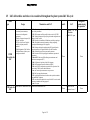
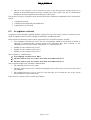
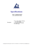
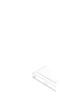
There are three I&C configurations of procured equipment as a consequence of the procurement model and
plant system sharing:
Configuration#1: The interface for I&C is the CODAC infrastructure as defined in PCDH. This
configuration is the IO standard model: the equipment is delivered as standalone plant system I&C
which is ready to be integrated. Typical examples are the buildings, the liquid nitrogen cryoplant,
the heating and diagnostic neutral beam facilities and some diagnostic systems. See Figure 2-1,
PA1.
Configuration #2: The interface for I&C is still the CODAC infrastructure as defined in PCDH, but
the procurement is a part a more extended plant system I&C. The I&C procurement is still
delivered as a PCDH compliant system, including a PSH and a mini CODAC like configuration#1
but this configuration assumes some integration work will be performed by IO to complete the
integration of the PS I&C (e.g. merging of mini CODAC and PSH configurations). Typical
examples may be found in the cryogenics and the water cooling plant systems. See Figure 2-1,
PA2.
Configuration #3: The interface for I&C is reduced to the signals provided by the sensors/actuators
or any controller embedded in the equipment . This configuration is typically used when the plant
I&C system is purchased by IO. A typical example is the Magnet system. See Figure 2-1, PA3.
PS I&C
PS I&C
PS I&C
Mini CODAC
Mini CODAC
Mini CODAC
CODAC networks
CODAC networks
CODAC networks
PSH
2A/B
Controller
2
Controller
1
PSH 1
PSH 3
Controller
5
Controller
4
Controller
3
Remote
I/O
Remote
I/O
Remote
I/O
Remote
I/O
Remote
I/O
Remote
I/O
Remote
I/O
Remote
I/O
Signal
interface
Signal
interface
Signal
interface
Signal
interface
Signal
interface
Signal
interface
Signal
interface
Signal
interface
PA1
PA2A
PA2B
PA3
Figure 2-1: I&C configuration types
2.4 I&C actors for FAT and SAT
Several actors are involved in FAT and SAT for I&C. Those introduced in this document are:
Plant System I&C Responsible Officer (PS I&C RO) – IO client of the I&C system. He/she
provides the plant system inputs throughout the design process. He/she reviews the plant system
I&C design, provides the PS I&C FAT and SAT plans, reviews and approves the results of the PS
I&C FAT and SAT. He/she is supported by the ITER Control System Division (CSD) for checking
compliance with PCDH requirements and implementation of CODAC solutions.
Procurement I&C Supplier (I&C SU) – supplies any I&C equipment or software including spare
units and documentation for the plant system in question. The scope of the supply is defined in
Annex B of the PA (in-kind procurement) or the technical specifications (when purchasing). The
configuration of the PSH and Mini-CODAC is a task of the procurement I&C SU, therefore the
procurement I&C SU is assumed to be skilled in using CODAC tools. The procurement I&C SU
executes the PS I&C FAT and SAT plans.
Page 8 of 35
2.5 I&C deliverables and rules to be considered throughout the plant system I&C life-cycle
Phase
Topic
PCDH
deliverables for
I&C
Design
D1 Plant system I&C architecture.
D5 Plant system controller(s)
performance and configuration
requirements.
D6 List of inputs and outputs (I/O)
of the I&C controllers.
D7 List of the Process Variables
handled by the plant system I&C
controllers.
D8 Configuration of I&C cubicles.
D9 Specifications of plant system
operating state machines.
Manufacture and FAT
D31: Functional specifications of the I&C system developed within the
scope of the procurement.
D32: SW documents and files specified in the section 4.4 of PCDH.
D34: Technical documents for specifying the internal configuration and
cabling of the I&C cubicle.
D39: Procedure for installation of all hardware and software packages.
D40: All original documents for mounting, cabling, configuring,
operating and maintaining any I&C equipment.
D41: Drawings showing the complete path of I&C signals from the
sensors/actuators up to the signal interfaces of the I&C controllers.
D42: Calibration factors for the sensors and the actuators.
D43: Extension of D40 for specifying the installation, operation and
maintenance.
D44 and D71: Short term (D44) and long term maintenance and
obsolescence management (D71)
D48: Certificates of conformity of the I&C equipment.
D20: Self-Description Data as described in and [SD4]
D26: mini CODAC configuration as required for the operation of the
system using CODAC systems and infrastructure.
D18: I&C cubicles procured within the scope of the PA.
D19: I&C spare parts for maintenance.
D74: is gathering all hardware and software tools required to maintain
non-standard I&C equipment.
D72: user software developed in the scope of the I&C for active control,
monitoring, simulation and testing purposes.
D50: FAT report
PCDH rules for Related rules are mentioned in sect. Related rules mentioned in sect. 7
8
I&C
Page 9 of 35
Install.
Integrated
commissioning
& operation
SAT
Update
of
deliverables
all
D65: SAT report
None
None
None
Related rules are
mentioned in sect. 7
None
3 Details of the FAT for I&C systems
3.1 FAT objectives for I&C and entering FAT
The objective of the plant system I&C FAT from the CENTRAl I&C perspective, is to check the readiness
of the PA for integration with the CENTRAL I&C.
Procured PA is considered as ready for the FAT if the following criteria are met:
The CENTRAL I&C interface data has been made available and updated in the IO Self Description
Data (SDD) repository.
The PCDH requirements specified for checking during design and manufacture phases are met.
The FAT plan is defined and agreed by all parties. The FAT plan must cover all I&C systems
interfaced to CENTRAL I&C for conventional, interlock and safety controls.
The software deliverables are stored in the correct IO repository.
The component list (bill of materials) is issued and it identifies all I&C deliverables as specified in
PCDH.
All of the certificates required are available.
The mini CODAC system is configured and ready to proceed to the FAT.
The supplier is ready to proceed.
FAT for I&C will target the remaining PCDH requirements to be checked on the relevant deliverables.
3.2 Scope of FAT for I&C systems
It is proposed to split the FAT for I&C into four campaigns as listed below:
C1.
I&C documentation.
C2.
I&C hardware.
C3.
I&C configuration data and software.
C4.
I&C functional requirements.
Each campaign is determined by the PCDH requirements and the I&C deliverables which have to be
checked.
A non-compliance severity level has been assigned to each PCDH requirement to be verified during the
FAT and SAT: see Section 6.1 for further details.
The details of the campaigns are given in the Chapter 7 of this document.
A mapping between the PCDH requirements and the campaigns is proposed in the Excel file incorporated
in Chapter 9.
3.3 Performing FAT for I&C systems
Preparing FAT in IO:
For each PA the following tasks will be performed by IO for testing the PA interfaces with the central I&C
systems:
Set up the suitable plant system I&C HW architecture matching the PA configuration with all
controller CPU chassis connected physically to the central I&C networks in IO lab (no remote IO
chassis is required provided there is no central I&C interface expected in the remote IO chassis).
The mini-CODAC and the PSH are parts of the architecture.
Check the configuration data and procedure of installation (PCDH deliverables are identified for
each). The versions of software and SDD deliverables stored in IO repository are used.
Test the PA-central I&C interface: The test procedure to apply is still TBD.
For the complete plant system I&C:
Set up the complete plant system control system HW architecture as for PA testing.
Test the functional links in between PAs involved in the plant system I&C.
Page 10 of 35
Performing FAT at supplier premises:
For efficiency, it is recommended that the campaigns are performed in the order as described in this
document.
The campaign C1 does not require any attendance of the PS I&C RO at the FAT site since it may be
performed remotely by IO using the deliverable documents. C1 is performed by the PS I&C RO with the
support of CSD.
The campaigns C2, C3 and C4 require the attendance of the PS I&C RO at the FAT site and the support of
CSD, but will be prepared at IO premises using the PCDH deliverable documents and the bill of materials.
C2 to C4 are performed by the I&C SU. See details in Sections 7.4, 7.5 and 7.6.
How to perform the campaigns in the scope of a FAT:
C1. Upload the deliverable documents in IDM/EDB (details are still TBD) and proceed to the
review them as specified in Section 7.3 for all items checked in the FAT column of the I&C
matrix1.
C2. Check the deliverables D18 (I&C cubicles), D19 (spare parts for I&C) and D79 (any specific
maintenance tools required) as specified in Section 7.4, for all items checked in the FAT column
of the I&C matrix2.
C3. Check the deliverables D20, D26 (SDD configuration data) and D72 (all I&C user software),
D74 (the SW tools required for the PS maintenance) as specified in Section 7.5, for all items
checked in the FAT column of the I&C matrix3.
C4. Check the deliverable D39 (HW and SW installation procedure) by executing D39 for complete
HW and SW installation as specified in Section 7.6. Check the Central I&C interfaces and all
functional requirements as specified in Section 7.6.
On completion of FAT, the FAT report (PCDH deliverable D50) is issued by the I&C SU and the test plan
is also updated if required.
4 Details of the assembly of procured equipment for I&C
systems
The unit of assembly for any I&C procurement is the I&C cubicle: the I&C is considered as assembled
when all I&C cubicles are mounted and physically interfaced, at their final location. The goal of plant
system I&C assembly is then to connect and set up the I&C cubicles with the CENTRAL I&C
infrastructure, buildings, power supplies and other services in order to get the plant system I&C ready for
the functional tests expected in SAT; the procurement assembly phase is performed under the responsibility
of the procurement supplier. The following tasks will be completed on each plant system I&C cubicle:
Configure the I&C cubicle for mounting and cabling: to prevent damage, the fragile internal
components are first removed, see [SD24] for details.
Install the I&C cubicle at its final location in the ITER building.
Cable the cubicle to the plant system equipment, to the CENTRAL I&C infrastructure (networks),
to the main power supply and to any other system required.
Complete the configuration of the HW internal and enclosure if some equipment had been removed
before mounting and cabling (fragile component, doors, …)
1
All document deliverables are expected to be reviewed at FAT.
All HW related rules are expected to be checked at FAT except the rules R59, R312, R313 and R315 which will be
checked at SAT.
3 All SW related rules are expected to be checked at FAT.
2
Page 11 of 35
5 Details of SAT for I&C systems
5.1 SAT objectives for I&C
From the CENTRAL I&C perspective, FAT target the plant equipment and SAT the plant system I&C.
Therefore the SAT objective is to check the readiness of the plant system I&C for integration with
CENTRAL I&C systems and infrastructure and to check the readiness of the plant system I&C for
integrated commissioning.
5.2 Scope of SAT for plant system I&C
The scope of SAT is identical to that of the FAT but extended to the plant system I&C, in particular where
plant system I&C comprises several procurements.
Some things may not be carried out during the FAT and as a consequence shall be transferred to the SAT:
The ultimate goal is to have checked all PCDH requirements by the completion of the SAT. By convention,
nothing is redone at the SAT when it has already been satisfied during the FAT and there is no I&C
configuration change from FAT to SAT.
Therefore the C1 campaign for documentation is not expected to be redone at SAT.
The SAT is organized in three steps: component tests and system tests as specified by [RD3] and a third
step for connection to the CENTRAL I&C infrastructure.
5.3 Performing SAT for plant system I&C
To make a complete check of the installation procedure, all of the software and configuration data
installed in controllers, mini-CODAC systems and PSH in the scope of the FAT will be deleted. The
equipment will be re-installed from scratch using CENTRAL I&C procedures for systems;
CENTRAL I&C source repository (SVN) files; configuration data; and the PCDH deliverable D39,
for the plant system I&C installation procedure.
Component tests:
The unit for component tests is the I&C cubicle of the plant system I&C. The goal of I&C cubicle tests is to
check the physical interfaces with CENTRAL I&C, buildings, power supplies and other services in order to
get the plant system I&C ready for the system tests; the component tests are performed by the I&C SU
under the responsibility of the PS I&C RO with support from the CSD throughout the following:
Carry out the electrical hazard safety inspection to obtain authorization for cubicle powering;
proceed to cubicle powering, check the cubicle cooling system. Once this has been done, the I&C
cubicle is considered as ready for the next step.
When all plant system I&C cubicles are ready, check the network configuration and connectivity of
all controllers (PSH included) for PON, TCN, SDN, AVN, DAN, CIN and CSN. Download the
SW configurations required for these tests to the I&C controllers. From that point, all active
controls are disabled at the controller level to avoid any unexpected automatic action which could
potentially disturb the tests or even damage the plant system.
It is assumed that the component tests are performed with the mini-CODAC. Then the miniCODAC configuration will be adjusted to match the component test scenario. Several miniCODAC systems might be required to execute the system tests, depending on the complexity of the
plant system I&C: these should be installed at the appropriate location defined by the PS I&C RO.
Check the PSH hardware configuration.
Execute the C2 campaign for HW and C3 for SW for all items expected to be checked at SAT and
all items not checked at FAT. See details in Sections 7.4 and 7.5.
Check the connectivity of the remote IO chassis with the CPU chassis for all controllers of the
plant system I&C: this procedure is still TBD.
Report the plant system I&C installation issues in the appropriate logging system (details are still
TBD), fix the remaining issues. The plant system I&C is then considered ready for the system tests.
Page 12 of 35
System tests:
The unit of system tests for I&C is the plant system I&C. The plant system I&C tests are part of plant
system tests; they concern the tests to be performed on plant system I&C to get it ready to complete the
system tests. The plant system I&C tests are performed by the I&C SU under the responsibility of the PS
I&C RO with support from the CSD throughout the following:
If several PSH have been introduced for dealing with a plant system I&C configuration delived in
several PAs by different partners, then these PSH shall be merged in only one at that point.
Execute the C4 campaign for functional requirements of all items checked in the SAT column in
the spread-sheet and all items not checked during the FAT. See details in Section 7.6.
Report the plant system I&C test issues in the appropriate logging system (still TBD), fix the
remaining issues.
Issue the plant system I&C SAT report: PCDH deliverable D65.
Enable the active controls in the controllers, the plant system I&C is then considered as ready to
complete the system tests under the responsibility of the plant system RO. This point is beyond the
scope of this document.
System connection to CENTRAL I&C and preparation for integrated commissioning:
The unit of system connection for I&C is the plant system I&C. After completion of the system tests, the
central I&C systems are updated with the plant system I&C data configuration for allowing the plants
system I&C to be operated from the Main Control Room (MCR); the plant system I&C mini-CODAC(s)
used for plant system I&C SAT are cancelled and removed from the plant system I&C. The PSH HW
delivered in scope of the integration kit is removed from the plant system I&C cubicles and is virtualized in
CENTRAL I&C systems.
If several plant system I&Cs are involved in the control of the plant system, an additional step targeting the
integrated operation of these plant system I&Cs will be performed following the completion of each
individual. This integrated operation is performed from the main control room under the responsibility of
the PS I&C RO who will specify the scope and the procedure for these tests.
Page 13 of 35
6 I&C Acceptance Principles
6.1 Issue management
During the execution of tests, any deviation from the expected result must be captured in a uniquely
identified issue sheet. All the information related to the investigation of the root cause of the issue and all
the remedial actions must be recorded in the sheet. The PCDH rules in Section 7.2 apply for any deviation
from PCDH rules.
Issue sheets must be recorded electronically and archived using the IO issue tracking tools at least.
A severity level value must be assigned to each issue reported as follows:
Severity Level 1: major issue that must be fixed before shipping of the procured equipment to the
ITER site.
Severity Level 2: an issue that may be fixed on the ITER site before the system commissioning.
Severity Level 3: minor issue acceptable for I&C integration to CENTRAL I&C infrastructure:
may be fixed later but before the final acceptance by IO.
The issue sheet will monitor the progress and resolution of the issue. The life cycle of the issue sheet must
have at least:
Open: the issue sheet has been created and contains the full description of the issue
Fixed: the root causes of the issue have been identified and the corresponding fix has been
delivered
Validated: the fix has been successfully re-tested, including non-regression tests. If the delivered
fix doesn’t pass the validation, the issue sheet status moves back to Open.
The Issue Sheet must record all the information related to the investigation of the root cause of the issue
and all the remedial actions throughout its lifecycle.
6.2 Acceptance process
IO and DA representatives (DA for in-kind procurements) attend the FAT and SAT for campaigns C2, C3
and C4.
An acceptance test plan will be issued by the I&C SU. A template for the test plan and report covering the
scope of I&C is available at: FAT-SAT plan and report for I&C (ATCLA4)
The result of the execution of the FAT and SAT plans for I&C is recorded in the FAT and SAT reports
(PCDH D50 and D65 respectively), which indicate:
The result of each test campaign part of the test plan:
- Fully Passed: the campaign is complete and all the scenarios have been successfully executed.
- Partially Passed: the campaign is complete but some of the scenarios failed.
- Blocked: an issue encountered in a certain scenario prevents the completion of the campaign.
- Not Executed: the campaign has not yet been executed.
The reference to any issue sheets raised for each campaign.
When an issue of Severity Level 1 is encountered, the IO and DA representatives (for in-kind procurement)
may decide either to stop the acceptance process (if they consider that the consequences of the defect are
either too important or that the remaining tests would not be valid) or to continue it.
Issues of Level 2 and Level 3 do not stop the acceptance process.
If the number of issues encountered requires the delivery of a new release to fix them, IO and DA
representatives and the supplier have to define and agree on the following:
The set of tests or checks to be re-executed for validating the fix. The aim is to demonstrate that the
fix does actually solve the issues it is supposed to address.
Page 14 of 35
The list of test scenarios to be re-executed as part of the non-regression testing, based on an
analysis of the potential impact of the fix on other parts of the system. The aim is to demonstrate
that the fix does not compromise the other parts of the system.
The progress of factory acceptance can be assessed by means of indicators maintained in the FAT and SAT
reports:
Campaigns executed.
Campaigns passed/partially passed/blocked.
Campaigns not yet executed.
6.3 Acceptance criteria
Acceptance criteria should be globally defined at project level by IO in order to ensure consistency across
all the acceptance-related activities and project milestones, including the FAT.
In the interim, the following criteria can be proposed for FAT and SAT acceptance for I&C:
Test campaign execution rate: this is the rate of campaigns which have been fully executed. A
campaign is considered fully executed when all its procedures have been executed, i.e. the
campaign execution result is either “Fully Passed” or “Partially Passed”.
Number of issues with Severity Level 1.
Number of issues with Severity Level 2.
Number of issues with Severity Level 3.
The acceptance is validated when:
Test campaign execution rate is 100%
All issues with Severity Level 1 have been fixed and validated for FAT.
All issues with Severity Level 2 have been fixed and validated for SAT.
The acceptance might be provisionally validated when:
The campaign execution rate is 100%
All issues with Severity Level 1 and all unacceptable issues with Severity Level 2 have been fixed
and validated.
All remaining Severity Level 2 issues are such that they do not make the use of the system
unreasonable in an operational mode.
Issues of level 3 cannot lead to a refusal of acceptance.
Page 15 of 35
7 Campaign details for FAT and SAT
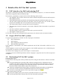
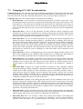
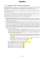
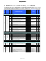
7.1 The PCDH requirement mapping matrix
The PCDH mapping matrix of requirements provides a mapping between PCDH requirements and:
The associated severity level for acceptance.
Whether any test is required for checking the requirement.
In which of the C1, C2, C3, and C4 campaigns the requirement should be checked.
Where the check must be performed: FAT or SAT. An “X” indicates if the check is mandatory, an
“O” if optional or acceptable. The procurement configuration is also considered at this stage, see
Section 2.3 for further details.
The PCDH requirement is identified by its PCDH section number, title, requirement/deliverable identifier
and description.
I&C funct.
I&C SW
Requirement Description
I&C HW
C1 C2 C3 C4
Test
req.
I&C Doc.
Severity level
PCDH
section title
PCDH Req#
PCDH section#
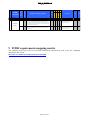
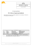
Table 1 provides an illustration of this mapping: the PCDH-R55 requirement is verified in the scope of the
C4 campaign for I&C equipment procured with configurations #1 and #2 only. Therefore, this requirement
will be checked during SAT for procurement configuration #3. In addition a test is required and the severity
level is assigned to 1.
Comments
FAT SAT
Plant system I&C Design Philosophy
Plant System I&C Life Cycle
Specification
Plant System I&C Architecture
Mini-CODAC
Mini-CODAC
4.2.1
[R52]
1
[R53]
[R54]
[R55]
1
[R56]
1
Mini-CODAC shall be used for FAT as a substitute for the CODAC
System.
OSI layer 2 switch is the only plant system I&C component that has
a physical interface with Mini-CODAC.
T he physical interface of the plant operation network between MiniCODAC and the plant system I&C shall be a conventional Gigabit
Ethernet connection.
T he functional interface of the plant system I&C shall be tested
with the Mini-CODAC.
T he software components delivered with the plant system I&C that
will be integrated into the CODAC System shall be tested with MiniCODAC.
x
x
x
x
none
X
O
Design requirement checked
during the design phase
-
-
Design requirement checked
during the design phase
-
-
x
none
X
O
x
T arget standard I&C equipment
only
X
O
Table 1: Illustration of the mapping matrix. The complete matrix is given in chapter 8.
Page 16 of 35
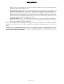
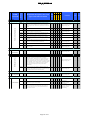
7.2 Rules applicable to all campaigns
I&C funct.
Test
req.
I&C SW
Requirement Description
I&C HW
C1 C2 C3 C4
I&C Doc.
PCDH
section title
Severity level
PCDH Req#
PCDH section#
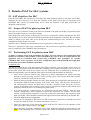
The rules mentioned in the Table 2 address the management of deviations from PCDH requirements and
are applicable to the complete I&C system life-cycle, including FAT and SAT. See PCDH for further
details.
Comments
FAT SAT
Plant system I&C Design Philosophy
Plant System I&C Life Cycle
Specification
Interface Specification between Plant System I&C and Central I&C systems
Interlock I&C Specification
Safety I&C Specification
Deviations Policy
Requests for deviations from and non-conformance with the
requirements of the IT ER Plant Control Design Handbook shall be
made to the IO in writing following the procedures detailed in
[RD11], [RD19] and [RD12]. T he decision on the acceptance of the
non-conformance report shall be made by the plant system central
I&C responsible officer of the IO.
[R281]
Deviations Policy
8
[R282]
[R283]
[R284]
[R285]
[R286]
1
1
1
1
1
[R287]
1
[R288]
[R289]
1
1
Any I&C equipment which is non-complaint to the PCDH
requirements shall be subject to the Non-Conformance Report
Process described in the IT ER Deviations and Non-Conformances
[RD12] and [RD19]. Every non-conformance shall be accompanied
by an obsolescence management plan as suggested by IEC 62402.
T he plant system responsible officer (and plant system I&C
supplier, if appropriate) has to provide and pay for special
integration and additional maintenance including spare parts for non
standard equipment.
A deviation request shall include an alternative proposal including a
justification of why I&C specifications in this document or
procurement document were not followed, and a list of attachments
which support the justification.
A non-conformance report shall include the original requirement, a
description of the non-conformance, proposed remedial action, and
a list of attachments which support the proposed remedial action.
If the plant system responsible officer (and plant system I&C
supplier, if appropriate) discovers that he had misinterpreted these
technical specifications after signing the PA, this shall not be
accepted as an excuse for deviations from it.
During execution of the procurement, all deviations from the
technical specifications shall be reviewed and finally approved by
IO.
IO shall consider the proposal on an expedited basis.
IO reserves rights to reject or accept such proposals.
Design requirement checked
during the design phase
-
-
x x x x
Apply to all campaigns
X
O
x x x x
Apply to all campaigns
X
X
x x x x
Apply to all campaigns
X
O
x x x x
Apply to all campaigns
X
O
x x x x
Apply to all campaigns
X
O
x x x x
Apply to all campaigns
X
O
x x x x
x x x x
Apply to all campaigns
X
X
O
O
Apply to all campaigns
Table 2: PCDH rules applicable to all campaigns and types of procured equipment for FAT and SAT
Page 17 of 35
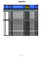
7.3 Campaign C1: I&C documentation
Campaign purpose: This campaign checks that PCDH rules applicable to the documents delivered in the
scope of a procurement are met. These documents are identified in PCDH as deliverables D31, D32, D34,
D38, D39, D40, D41, D42, D43, D44, D48, D60 and D71. They are all provided by the I&C SU.
Campaign scope: The relevant deliverables are identified in the PCDH as:
Deliverable D31: is the relevant set of functional specifications of the I&C system. D31 covers
the detailed description of the active controls and the monitoring of the plant system function. This
deliverable has a free format and is checked by the PS I&C RO for completeness with respect to
other technical specifications. D31 covers all of the plant system functions including conventional,
interlock and safety functions in the scope of the PA and must be delivered for all configurations
(#1 to #3).
Deliverable D32: is the set of SW documents and files produced with the engineering tools
defined by IO in Section 4.4 of PCDH. D32 is checked by the PS I&C RO with the support of the
CSD for compliance with the technical specifications and with PCDH requirements. D32 must be
delivered for I&C equipment with configurations #1 and #2.
Deliverable D34: is the set of technical documents for specifying the internal configuration and
cabling of cubicles. Satellite document [SD24] is a guideline unless something falls within the
scope of IO cabling rules [RD2]. This deliverable has a free format and is checked by the PS I&C
RO against the technical specifications, against the cabling rules [RD2] and any additional
requirement related to the cubicle installation and environmental constraints (see [RD4]). D34 must
be delivered for I&C equipment with configurations #1 and #2. The rules related to the selection of
the hardware are checked in scope of campaign C2. D34 must include a bill of materials for the
I&C cubicle parts.
Deliverable D38: is the set of cabling drawings to be provided for cabling the I&C cubicles to the
plant system equipment and to CENTRAL I&C infrastructure. IO cabling rules apply [RD2] to
D38; it is checked by the PS I&C RO for completeness and compliance with [RD2].
Deliverable D39: is the procedure for installation of all hardware and software packages provided.
The procedure must be detailed enough to be used in the scope of campaign C4 to check the
capability of IO to replace any I&C hardware parts and reinstall any software package. D39 is
checked against a CSD template for completeness in the scope of the campaign C1. (template is
TBD).
Deliverable D40: comprises all original documents provided by I&C equipment suppliers
concerning mounting, cabling, configuring, operating and maintaining any I&C equipment. A nonexhaustive list of I&C equipment is: I&C controllers and parts of controllers (chassis, boards,..),
signal interfaces and power supplies, network interfaces and switches, cubicles and accessories
including cubicle heating, ventilation and air conditioning (HVAC) and monitoring systems. It is
assumed a bill of materials is provided by the procurement supplier; the PS I&C RO checks the
completeness of D40 with respect to the bill of materials.
Deliverable D41: in addition to the cabling diagrams used for on-site installation, D41 is the set of
drawings showing the complete path of I&C signals from the sensors/actuators up to the signal
interfaces of the I&C controllers. The path is through junction boxes, signal conditioning devices,
terminal blocks and other power supplies involved in the generation of the signals. The purpose is
to facilitate signal failure analysis by providing a complete picture of the signal route for each I&C
signal D41 is checked by the PS I&C RO.
Deliverable D42: concerns the calibration factors for the sensors and the actuators used in the I&C
controllers. These calibration factors are part of the plant system configuration data. See PCDH and
SDD for details. D42 may be part of D40 and is checked by the PS I&C RO.
Deliverable D43: D43 is an extension of D40 and concerns the documents issued during the
manufacturing phase by the I&C SU specifying the installation, operation and maintenance.
Therefore, these documents are procurement-specific and mainly cover procedures and user
Page 18 of 35
manuals. They are checked by the PS I&C RO with the support of CSD for everything linked to
CENTRAL I&C interfaces and services.
Deliverables D44 and D71: concern the short term (D44) and long term maintenance and
obsolescence management (D71) for any I&C equipment not compliant with PCDH standards. It is
assumed that CSD will manage obsolescence issues related to PCDH standards for HW and SW.
Therefore the I&C SU must propose a solution or at least a roadmap to resolve the obsolescence
problem for any non-compliant equipment during its life-cycle on ITER plant. D44 and D71 are
checked by the PS I&C RO with support from CSD.
Deliverable D48: these are the certificates of conformity concerning regulations applicable at
ITER site for the I&C equipment. D48 checking may be incorporated with checking of any other
procurement equipment (non I&C included).
The PCDH rules applicable to campaign C1 are the general IO rules for documents. In addition, rules R18,
R20, R21, R22, R43, R44, R45 and R46 for document management and quality apply, see Table 3 for
details.
The deliverable documents mentioned above can be merged together for optimization of delivery
purposes. If so, these documents must include a mapping table between PCDH deliverables and
sections and the delivered documents.
Page 19 of 35
I&C funct.
I&C SW
Requirement Description
I&C HW
C1 C2 C3 C4
Test
req.
I&C Doc.
Severity level
PCDH Req#
PCDH section#
PCDH
section title
Comments
FAT SAT
Plant system I&C Design Philosophy
Plant
SystemI&C
I&C Life Cycle
Plant System
Development
I&C
Deliverables
Management
I&C Deliverables
Management
3.4.1
[R18]
2
[R20]
2
[R21]
2
[R22]
1
[D31]
1
Outputs or deliverables shall be identified and managed to ensure that
IO and involved DAs know that they have the correct version and
shall be advised of any changes and/or deficiencies. Each output shall
be recorded with at least the output identifier/name, the type, the
description, the current version and the status (not built, built,
reviewed and approved).
x
T argets all life cycle deliverables
X
O
All deliverables shall be traceable to their parent output as well as to
their relevant specification and design item.
All deliverables in electronic format shall be backed up after the
acceptance phase in order to secure a functional restore state.
x
X
O
X
O
All deliverables shall be approved by IO.
x
T argets all life cycle doc
deliverables
T argets all life cycle doc
deliverables
T argets all life cycle doc
deliverables
X
O
x
Part of check under PS RO scope
X
O
Full software and configuration documentation as generated by the
IT ER IO prescribed engineering tools.
Every document required for cubicle mounting, air conditioning,
assembly, external and internal wiring, earthing and powering.
Inventory of any equipment or component used for cubicle
manufacturing (including I&C equipment), with supplier
identification and a supplier procurement reference
x
T argets IO standard controllers
X
O
x
SCC and LCC
X
O
Cabling documents for cubicle connection with I/O cabinets, I&C
Networks, earth and power supplies.
Procedure of installation, configuration, starting up and software and
hardware completeness checks for the plant system I&C in
particular for plant system specific components (non- standard
components).
x
Including I/O cabling to all I&C
equipment
X
O
none
X
O
x
none
X
O
x
none
X
O
x
none
X
O
x
none
X
O
x
none
X
O
x
none
X
O
x
none
X
O
x
T argets the non standard
equipment
X
O
x
none
X
O
x
none
X
O
x
x
none
X
X
O
O
x
I&C manufacture
3.4.3
I&C manufacture
[D32]
1
[D34]
1
[D38]
1
[D39]
1
[D40]
1
[D41]
1
[D42]
1
[D43]
1
[D44]
1
[D48]
1
Detailed descriptions (text documents including structured lists in
self-description data format) of: Process control for any plant
system operation state. Process failure detection and strategy for
process control. I/O treatments. Data exchanges required for slow
and fast controls. Feedback controls. HMI, alarms and events.
Software architecture for these items with identification of related
software modules and data exchange links.
Original technical documentation for each piece of equipment or
component (including software) used to manufacture the systems in
an I&C cubicle.
Schematic diagrams of the full signal path from the sensors/actuators
to the I/O boards of the controllers including powering and
conditioning, with identification of test points for fault analysis or
calibration and identification of the terminal blocks. T rouble
shooting procedures and functions.
Calibration factors for each sensor-actuator-conditioner-I/O board
and procedures for re-calibration of these components.
T echnical documents, manuals and procedures required for
maintenance of any I&C component.
Maintenance plan: detailed warranty and/or maintenance periods and
their possible extensions, licensing requirements.
Certificates of conformity for I&C procurement to any regulation
applicable on IT ER site and proof of compliance to IT ER I&C
standards.
x
x
x
I&C Factory
Acceptance
Tests
3.4.4
I&C Factory Acceptance Tests
[R25]
1
T he results of FAT shall be recorded and retained in the lifetime
records of the IT ER plant. Any failures during FAT shall be
investigated and the cause and rectification of the failure
documented in the FAT report. A complete bug report (problems
and fixes) must be provided and maintained during all life-cycle
phases.
I&C Acceptance Tests
3.4.9
I&C Obsolescence Management
I&C
Obsolescence
Management
[D71]
2
A proactive management plan for obsolescence describing the
strategies for identification and mitigation of the effects of
obsolescence throughout all stages of I&C life cycle
I&C Documentation
3.4.11
I&C Documentation
[R43]
[R44]
1
All documentation shall be in the English language.
2
All documentation shall be available in editable electronic format
(PDF, Open Document XML format or Microsoft Word) and in an
online version which is accessible using IO product lifecycle
management system.
[R45]
2
All documentation shall be under version control.
[R46]
2
For every item (including 3rd party and COT S) the original
documentation shall be delivered.
Table 3: Deliverables and rules for campaign C1
Page 20 of 35
none
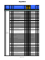
7.4 Campaign C2: I&C hardware
Campaign purpose: This campaign checks the PCDH rules applicable to the I&C hardware (HW) are
met. No I&C cubicle powering or tests are required for C2 campaign. The HW deliverable acceptance is
granted subject to a limited number of PCDH rules, assuming other relevant rules have been checked
during design and manufacture phases.
Campaign scope: The C2 scope is the HW delivered in scope of the PA: D18, D19 and D74:
Deliverable D18: it is assumed all I&C equipment as defined in PCDH and in the scope of the PA
will be installed in cubicles and these cubicles will be compliant with the IO standards defined in
PCDH, see section 4.5.3. Hence, D18 is the set of I&C cubicles which are ready to be integrated in
the plant system I&C architecture. The detailed HW configuration is given in D34. No I&C cubicle
is expected for procured equipment with configuration #3. D18 will be checked by the PS I&C RO.
Deliverable D19: comprises the spare parts for I&C maintenance. The quantity and scope of the
spare parts is normally specified in Annex B of the PA. D19 will be checked by the PS I&C RO
against what is specified in Annex B of the PA.
Deliverable D74: gathers all of the hardware tools required to maintain non-standard I&C
equipment. Only R24 applies to this deliverable; the scope is plant system specific and must be
determined on a case by case basis. D74 will be checked by the PS I&C RO.
The PCDH rules to apply on HW deliverables are mentioned in Table 4. Additional details are given
below:
I&C equipment:
Check the compliance with IO standards of the equipment delivered using product catalogues
[SD12] to [SD15]. See rules R132, R133, and R157.
Check the naming of I&C equipment: see rules R65 and R66. The cubicle enclosure, the controller
chassis and remote IO chassis (slow and fast controllers), the PSH and switches and all external
cables connected to the cubicles must be labelled and named accordingly. The guidelines for
cubicle tagging are given in [SD24] and for cable tagging in [RD2].
Check the conformity of the I&C HW configuration with the rules related to reserved slots and
load ratios.
- Rules R105 and R107 must be checked for each controller configuration (slow and fast).
- Rule R106 must be checked against the cubicle HW configuration for the space remaining
available for HW extensions.
Physical interface with the plant system equipment (signals):
Cables and cabling, (Rule R159): Check the compliance of the cabling interface and the cubicle
cable entries with the cabling rules of [RD2].
Physical interface with IO infrastructure (at the limit of the scope of PCDH):
Mechanical interface with the building: Check the cubicle fixings against what was specified by
IO.
Power supply: check that the power supply configuration is as specified in rule R199.
Environmental condition compliance (rule R179): must be considered at design phase but may be
assessed again at the installation phase.
Cubicle configuration with respect to access for maintenance (rule R180): this point is related to
the configuration of the doors. Check that he cubicle door configuration and access to internal
equipment conforms with what was specified by IO.
Cubicle cooling: if some connection to an external cooling device is required, check the
configuration of the interface. If not, check the configuration of the air inlet and outlet with respect
to what was specified by IO.
Page 21 of 35
I&C funct.
I&C SW
I&C HW
Requirement Description
Test
req.
I&C Doc.
C1 C2 C3 C4
Severity level
PCDH Req#
PCDH section#
PCDH
section title
Comments
FAT SAT
Plant System I&C Life Cycle
I&C manufacture
[D19]
1
2
[D74]
x
SCC and LCC
X
O
I&C spare parts list with appropriate specifications of storage space
and conditions
x
T opic sometimes specifically
discussed for the whole
procurement
X
O
1
T ools required for maintenance of any I&C component.
x x
none
X
O
2
For every test (unit testing; system and integration testing;
acceptance testing) the version of the equipment being tested, the
version of the test specifications being used and, for acceptance
testing, the version of the design specification being tested against,
shall be recorded.
x x
T argets all configurable I&C
equipment
X
X
x x
Includes the tools used to
configure and maintain the
sensors and actuators
X
O
A convention for uniquely identifying parts and components for
IT ER is defined in the IT ER Numbering System for
Parts/Components, see [RD3]. T his naming convention is applicable
to any component of the plant system I&C
x
none
X
O
1
T he component naming convention, as defined in the previous
section, applies to the component identifier.
x
none
X
O
[R105]
1
x
X
O
1
Additional reserve slots (not equipped) per backplane type shall be
more than 20%.
Additional reserve I/O channels (not equipped) per type shall be
more than 20%.
Additional reserve I/O channels (equipped) per type shall be more
than 5%.
none
Non-functional [R106]
Requirements
x
none
X
O
x
none
X
O
x
T o be checked at FAT but at
earlier stage for risk mitigation
X
O
x
T o be checked at FAT but at
earlier stage for risk mitigation
X
O
T o be checked at FAT but at
earlier stage for risk mitigation
X
O
x
T o be checked at FAT but at
earlier stage for risk mitigation
X
O
x
Integration requirement to be
checked at SAT
-
X
x
Integration requirement to be
checked at SAT
-
X
x
Integration requirement to be
checked at SAT
-
X
3.4.3
[D18]
I&C
manufacture
I&C cubicles with internal wiring and all internal I&C equipment
I&C Factory Acceptance Tests
3.4.4
[R23]
I&C Factory
Acceptance
Tests
[R24]
1
Plant System I&C
Specification
T he procurement I&C supplier shall provide all necessary hardware
and software tools and configuration files for FAT
Plant System I&C Architecture
4.3.1
I&C Naming Conventions
Components
Naming
Conventions
[R65]
[R66]
1
4.4.2
Non-functional Requirements
[R107]
1
X
Plant System I&C Hardware Specification
X
4.5.1
Plant System Slow Controller
Plant System
Slow Controller
[R132]
1
Slow controllers shall use the Siemens Simatic S7-300 or S7-400
ranges.
4.5.2
Plant System Fast Controller
1
Fast controllers shall be based on PCI Express I/O bus system.
[R157]
2
T he I&C cubicles shall be equipped with a monitoring system for
doors, temperature and cooling monitoring and the monitoring
system shall be interfaced to the plant system I&C.
[R159]
2
T he IT ER cabling rules apply to signal cabing
Plant System [R133]
Fast Controller
4.5.3
I&C Cubicles
I&C Cubicles
x
x
x
4.5.4
I&C Signal Cabling Rules
I&C Signal
Cabling Rules
4.5.6
Bondering - Powering
[R199]
1
Bondering Powering
Plant system I&C shall use Class-IV power supply as defined in
EDH, [RD4] single phase for conventional cubicles. T he PIS and
PSS will use Class II – IP and may be backed up by Class IV, see
chapter 6 and 7 of that document
Environment, Location and Volume Management
4.5.7
[R179]
Environment,
Location and
Volume
Management
[R180]
1
2
I&C equipment shall comply with the environment conditions of
the location at which they will be installed. If not a suitable
protection shall be defined for the I&C equipment. Such conditions
concern magnetic fields, neutron flux, electromagnetic radiation,
vibration coming from other equipment or seismic event,
temperature and humidity
Access to the instrumentation, cubicles and junction boxes shall be
sufficient to allow installation of testing and calibration equipment
Table 4: Deliverables and rules for campaign C2
Page 22 of 35
7.5 Campaign C3: configuration data and software
Campaign purpose: This campaign checks that the PCDH rules applicable to I&C software (SW)
packages are met. No SW deliverable tests are required for the C3 campaign; the SW deliverable
acceptance is granted subject to a limited number of PCDH rules, assuming other relevant rules have been
checked during design and manufacture phases.
Campaign scope: The relevant deliverables are identified in the PCDH as D20, D26, D72 and D74; they
are all provided by the I&C SU:
Deliverable D20: comprises the Self-Description Data as described in PCDH Section 4.4.6 and
[SD4]. The SDD includes references to signals, variable and process variables (PV). The content of
D20 is checked against the configuration and naming conventions for I&C components, signals and
variables, network configurations, see the associated rules in Section 4.3.1 of PCDH. D20 must be
delivered using the dedicated CODAC SDD editor. D20 includes the implementation of COS and
the mapping of COS with the specific PSOS. D20 is checked by the the PS I&C RO with the
support of IO CSD.
Deliverable D26: comprises the HMI configuration of the mini-CODAC, archiving and alarm
handling required for future operation using CENTRAL I&C systems and infrastructure. In
addition D26 includes what is required to perform the SAT and FAT as described in this document,
see Chapters 3 and 5. D26 must be delivered using the dedicated tool kit of the core CODAC
version in use at FAT date. D26 is checked by the the PS I&C RO with the support of IO CSD.
Deliverable D72: gathers all user software specifically developed for the I&C for active control,
monitoring, simulation and testing purposes (FAT, SAT, any other tests). D72 includes all
configuration data files used to configure the I&C equipment installed in the I&C cubicles but also
the sensors and actuators. D72 does not include the Self Description Data identified as deliverable
D20 in the PCDH. D72 will be checked by the PS I&C RO with the support of the IO CSD.
Deliverable D74: comprises all of software tools required to maintain non-standard I&C
equipment. Only R24 applies to this deliverable; the scope is plant system specific and must be
determined on a case by case basis. D39 will be checked by the PS I&C RO.
The PCDH rules to apply to SW deliverables are listed in Table 5. Additional details are given below:
SW storage:
SDD data, deliverable D20: use the IO SDD repository, see core CODAC user manual for the
procedure to apply.
Mini-CODAC configuration, deliverables D26 and D72: use the IO SVN repository at
https://svnpub.iter.org/codac/iter/codac/icdev/units/, see core CODAC user manual for the
procedure to apply.
SW validation:
SDD: The SDD data must pass the integrity, completeness and compliance validation of the SDD
editor.
PLC:
- R297 will be checked by compilation of the PLC user software on a STEP7 engineering station
configured with the STEP7 version specified in PCDH.
- The user software architecture of the PLCs will be checked against the PLC software
engineering handbook [SD10].
Fast controllers:
- R111, R112 and R118 for EPICS version and data communication apply.
- R113 applies to the OS version.
- FPGA: R119 applies.
PSH - mini CODAC: R155 applies for the core system version.
Page 23 of 35
I&C funct.
I&C SW
I&C HW
Requirement description, refer to the Test
approved document for details
req.
I&C Doc.
Severity level
PCDH Req#
PCDH section#
PCDH
section title
C1 C2 C3 C4
Comments
FAT SAT
Plant System I&C Life Cycle
I&C manufacture
I&C manufacture
3.4.3
[D72]
1
Source code of any software developed for the plant system I&C for
operation, factory acceptance test, site acceptance test, integrated
commissioning and maintenance, in the scope of the PA.
Configuration data for any plant system I&C controller to be
downloaded.
x
T argets mainly IO standard
controllers, to be discussed on a
case by case basis for specific
embedded controllers
X
O
x
Using IO tools
X
O
x
For FAT , SAT and plasma
operation
X
O
[D20]
[D26]
1
1
Plant system I&C self-description data
Mini-CODAC: configuration developed in Mini-CODAC
environment required for factory acceptance test, site acceptance
test and integrated operation
[D74]
1
T ools required for maintenance of any I&C component.
x x
none
X
O
2
For every test (unit testing; system and integration testing;
acceptance testing) the version of the equipment being tested, the
version of the test specifications being used and, for acceptance
testing, the version of the design specification being tested against,
shall be recorded.
x x
T argets all configurable I&C
equipment
X
X
x x
Includes the tools used to
configure and maintain the
sensors and actuators
X
O
x
none
X
O
x
none
X
O
x
none
X
O
x
none
X
O
x
x
none
X
X
O
O
x
none
X
O
I&C Factory
Acceptance Tests
3.4.4
I&C Factory Acceptance Tests
[R23]
[R24]
1
[R69]
1
[R68]
1
[R153]
1
[R154]
1
[R155]
1
[R111]
1
[R113]
1
T he Operating System of the PS fast controllers is Red Hat Linux
6.1 x86_64, desktop with workstation option.
2
T he software versioning control tool shall be Subversion.
x
none
X
O
[R297]
1
x
none
X
O
[R118]
1
1
x
x
none
[R119]
PLCs shall be programmed with the engineering software ST EP7
v5.5 or above.
Fast controllers shall be programmed using the CODAC Core System
distribution version 3.0 or above.
T he core CODAC supports following development tool chains:
X
X
O
O
Plant System I&C
Specification
T he procurement I&C supplier shall provide all necessary hardware
and software tools and configuration files for FAT
Components Naming
Conventions
4.3.1
I&C Naming Conventions
T he following naming convention [SD1] applies to I&C signals and
process variables (PVs).
T he plant system function identifier shall be based upon a Control
Breakdown Structure (CBS) and satisfy the following naming
convention:
By analogy with the signals, the convention for naming variables is
T he variable identifier is a free string of 16 characters maximum
VV…VV, provided the full name including the function identifier is
unique within the whole IT ER plant
PS I&C SW specifications
4.4.3
Software Infrastructure
Software
Infrastructure
CODAC core system version 3.0 or above shall be used on MiniCODAC and PSH
EPICS version R3.14.12 shall be used for PS fast controllers.
none
4.4.4
Operating Systems
Operating
Systems
Programming Languages and Tools
[R115]
none
Table 5: Deliverables and rules for campaign C3
Page 24 of 35
7.6 Campaign C4: I&C functional requirements
Campaign purpose: This campaign aims to check that the PCDH rules related to functional requirements
of the plant system I&C systems are met. A prerequisite of the C4 campaign is the completion of
campaigns C1 to C3 since the deliverables associated with them are required for C4 execution.
Campaign scope: The relevant deliverable identified in PCDH for the installation of the plant system I&C
is D39. In addition to D39 check, the tests of the functional interfaces between Central I&C systems and
the equipment are performed.
The tests related to the active control of the plant system equipment are beyond the scope of this document.
These tests may be performed after the C4 campaign at the request of the procurement RO. In such a case
they will be specified and executed under the responsibility of the procurement RO.
The PCDH rules to be checked in the scope of C4 are mentioned in the Table 6. These rules will be
checked by the PS I&C RO with the support of the IO CSD and will comprise:
Deliverable D39 checking: D39 is the procedure for installation of all hardware and software
packages provided in the scope of the PA. The procedure D39 is checked against an IO template for
completeness in the scope of the campaign C1 and is checked for HW and SW installation suitability
in the scope of the C4 campaign.
Functional requirements checking: the functional interface with central I&C systems is specified in
the plant system interface sheets for PBS45 to PBS48 (CODAC, Central Interlock, Plant Control
System and Central Safety System). PCDH Section 5.2 provides the rules to apply. It is assumed that
the I&C system is configured with a mini-CODAC and PSH computers for testing of the functional
interfaces with CENTRAL I&C in order to comply with R52, R55 and R56 rules. As a consequence,
the mini-CODAC must be configured to implement all of the CENTRAL I&C functions mentioned in
the interface sheets. With these boundary conditions, the functional interface with CENTRAL I&C
systems is checked as follows:
- State data, simple commands and configuration data over PON: This tests signal
connectivity from signal interfaces in the I&C cubicle up to the central I&C operator interfaces.
During these tests, the active controls are disabled at controller level to avoid any un-expected
automatic action which could potentially disturb the tests or even damage the plant system. The
test procedure is performed as follows:
o Inputs (digital and analogue): For each controller interface board, the input signals are
simulated at the signal terminal block level and the continuity of the data processing
including any data treatment up to the mini-CODAC display is checked. The procedure to
apply is TBD.
o Outputs (digital and analogue) and internal variables: The associated variables are
simulated/forced in the controller. The procedure to apply is TBD.
o Health monitoring data: The procedure to apply is TBD.
o COS management: The procedure to apply is TBD.
- Time synchronization over TCN: The procedure to apply is TBD.
- Data over SDN: The procedure to apply is TBD.
- Data over DAN: The procedure to apply is TBD.
- Data over AVN: The procedure to apply is TBD.
- Data over CIN: The procedure to apply is TBD.
- Data over CSN: The procedure to apply is TBD.
Page 25 of 35
x
I&C funct.
Procedure of installation, configuration, starting up and software and
hardware completeness checks for the plant system I&C in
particular for plant system specific components (non- standard
components).
I&C SW
Requirement Description
I&C HW
C1 C2 C3 C4
Test
req.
I&C Doc.
Severity level
PCDH Req#
PCDH section#
PCDH
section title
Comments
FAT SAT
Plant System I&C Life Cycle
3.4.3
I&C manufacture
I&C
manufacture
[D39]
1
x
x
X
O
x
-
X
x
x
-
X
x
x
-
X
x
x
Check under PS RO responsibility
for scope and procedure
-
X
x
x
none
X
O
x
x
none
X
O
x
x
T arget standard I&C equipment
only
X
O
x
x
Functional requirement to be
checked at SAT
-
X
x
x
Functional requirement to be
checked at SAT
-
X
x
T o be checked at FAT but at
earlier stage for risk mitigation
X
O
x
none
X
O
none
I&C Acceptance Tests
3.4.6
[R30]
I&C
Acceptance
Tests
1
[R371]
1
[R372]
1
[R373]
1
Plant System I&C
Specification
T he results of SAT shall be recorded and retained in the lifetime
records of the IT ER plant. Any failures during SAT shall be
investigated and the cause and rectification of the failure
documented in the SAT report
SAT is performed with Mini-CODAC. Mini-CODAC may be
complemented by specific tools for the PIS and PSS.
Data links with Mini-CODAC not tested during FAT shall be tested
during SAT . See [SD6] for details for FAT .
For performance test purpose, the plant system I&C shall be tested
under a scenario and acceptance criteria provided by the IT ER plant
system RO. T his scenario shall include the individual tests of every
plant system I&C function with the real process connected to the
plant system I&C and the test of the plant system as a complete
autonomous system, without any interaction with Central I&C
Systems
Plant System I&C Architecture
4.2.1
Mini-CODAC
Mini-CODAC
Mini-CODAC shall be used for FAT as a substitute for the CODAC
System.
T he functional interface of the plant system I&C shall be tested
with the Mini-CODAC.
T he software components delivered with the plant system I&C that
will be integrated into the CODAC System shall be tested with MiniCODAC.
[R52]
1
[R55]
1
[R56]
1
[R77]
2
[R78]
2
[R157]
2
T he I&C cubicles shall be equipped with a monitoring system for
doors, temperature and cooling monitoring and the monitoring
system shall be interfaced to the plant system I&C.
1
T he functional interface of the plant system I&C shall be tested
with the Mini-CODAC.
PS I&C SW specifications
4.4.1
Functional requirements
Functional
requirements
T he plant system I&C shall be able to autonomously maintain safe
operation of the plant system in case of loss of central I&C systems
or I&C networks (not applicable to PSS).
T he start-up strategy shall take into account the current state of the
process and the presence/absence of the CODAC system (not
applicable to PSS).
4.5.3
I&C Cubicles
I&C Cubicles
x
x
6.2
Interlock I&C Specification
Interlock I&C
Architecture
[R332]
Table 6: Deliverables and rules for campaign C4
Page 26 of 35
8 PCDH rules not considered during FAT and SAT
I&C funct.
I&C SW
I&C HW
Requirement Description
Test
req.
I&C Doc.
C1 C2 C3 C4
Severity level
PCDH
section title
PCDH Req#
PCDH section#
The following rules must be checked during the design and manufacturing phases: They are assumed
to have been met for the FAT and therefore will not be considered in the definition of FAT and SAT
scenarios and any acceptance criteria.
Comments
FAT SAT
Plant system I&C Design Philosophy
2.3
Plant system I&C mandatory functional requirements
Plant system I&C mandatory functional requirements
[R1]
Plant system I&C shall perform control of the plant system under
the authority of CODAC during any operating state.
Design requirement checked
during the design phase
-
-
[R2]
Plant system I&C shall comply with project-wide supervisory
control functions and central data handling functions (i.e. archiving,
monitoring, logging and visualization) provided by CODAC System.
Design requirement checked
during the design phase
-
-
Design requirement checked
during the design phase
-
-
Design requirement checked
during the design phase
-
-
Plant system I&C shall be designed to be configurable from MCR
using its self-description data.
Plant system I&C shall be operated centrally from MCR.
Design requirement checked
during the design phase
-
-
Design requirement checked
during the design phase
-
-
[R11]
Permanent local control rooms are forbidden. T here are two
exceptions to this rule; remote handling and tritium plant.
Design requirement checked
during the design phase
-
-
[R12]
Plant system I&C shall use Mini-CODAC as a tool for plant system
software development support, integration, factory acceptance test
and site acceptance test. Mini-CODAC will be complemented by
certified tools for PIS and PSS.
Plant system I&C shall have built-in absolute-limit protection to
prevent local control and central control errors. T ime critical
devices shall have built-in time-outs to ensure correct operation in
case of Central I&C Systems failure.
Design requirement checked
during the design phase
-
-
Check under PS RO responsibility
for scope and procedure
-
-
[R3]
[R4]
[R5]
[R10]
[R15]
Plant system I&C shall make available all data acquired from
sensors/actuators, with a time stamp, to Central I&C Systems for
analysis, archiving, logging, monitoring and visualization. T he
principle of “ no hidden data” is applicable for all plant systems I&C;
there shall be no permanent local storage of data.
Plant system I&C shall provide status information for common
operating states, plant system operating state, alarm conditions, trip
conditions and corrective actions, control system set points and
power supply status information that is required to operate the plant
system I&C from Main Control Room (MCR).
Plant
SystemI&C
I&C Life Cycle
Plant System
Development
I&C Obsolescence
Management
3.4.9
I&C Obsolescence Management
[R291]
T he latest PCDH version available shall be applicable when the PA
is signed
Operation/maintenance phase
relevant only
-
-
[R37]
IO is committed to support old versions of PCDH standards,
including the obsolescence management of those standards.
Every new I&C equipment shall be documented in the same way as
was required for the initial procurement.
Operation/maintenance phase
relevant only
-
-
Operation/maintenance phase
relevant only
-
-
[R40]
T raining for operation and maintenance teams shall be included in
the process of replacement, if required.
Operation/maintenance phase
relevant only
-
-
[R41]
T he plant system ROs shall define requirements for their plant
system I&C backup and storage by successive evolutions and the
strategy to adopt in case of obsolescence.
Check under PS RO responsibility
for scope and procedure
-
-
OSI layer 2 switch is the only plant system I&C component that has
a physical interface with Mini-CODAC.
T he physical interface of the plant operation network between MiniCODAC and the plant system I&C shall be a conventional Gigabit
Ethernet connection.
Design requirement checked
during the design phase
-
-
Design requirement checked
during the design phase
-
-
[R59]
[R60]
Each plant system I&C shall have one and only one PSH.
none
T he PSH shall be connected to the OSI layer 2 switch.
-
-
[R61]
T he PSH shall be integrated into the plant system I&C.
-
-
[R62]
5U [T BC] in a 19” rack and 500W power supply shall be allocated
for the PSH in one of the plant system I&C cubicles.
T he interface between the PSH and the plant system controllers
shall be Ethernet.
T he PSH shall be configured by the plant system I&C designers using
the software kit supplied by IO.
Design requirement checked
during the design phase
Design requirement checked
during the design phase
Design requirement checked
during the design phase
Design requirement checked
during the design phase
Design requirement checked
during the design phase
-
-
-
-
-
-
[R38]
Plant System I&C
Specification
Plant System I&C Architecture
MiniCODAC
4.2.1
Mini-CODAC
[R53]
[R54]
Plant System Host
4.2.2
Plant System Host
[R63]
[R64]
Page 27 of 35
I&C funct.
I&C SW
I&C HW
C1 C2 C3 C4
Requirement description, refer to the Test
approved document for details
req.
I&C Doc.
Severity level
PCDH Req#
PCDH section#
PCDH
section title
Comments
FAT SAT
Plant system I&C Design Philosophy
Plant System I&C
Specification
4.3.1
I&C Naming Conventions
Components
Naming
Conventions
[R67]
T he signal identifier shall satisfy the following naming convention:
T he signal identifier is made of three parts:
none
-
-
Design requirement checked
during the design phase
-
-
Design requirement checked
during the design phase
-
-
Design requirement checked
during the design phase
-
-
Design requirement checked
during the design phase
-
-
Design requirement checked
during the design phase
-
-
Design requirement checked
during the design phase
-
-
Design requirement checked
during the design phase
-
-
Design requirement checked
during the design phase
-
-
Design requirement checked
during the design phase
-
-
Design requirement checked
during the design phase
-
-
Design requirement checked
during the design phase
-
-
Design requirement checked
during the design phase
Design requirement checked
during the design phase
-
-
-
-
-
-
Design requirement checked
during the design phase
-
-
Design requirement checked
during the design phase
-
-
none
-
-
Needs the whole conf of PS I&C
to be checked
-
-
Design requirement checked
during the design phase
PS I&C SW specifications
Functional requirements
[R70]
T he plant system I&C shall implement the following functions:
[R71]
All information issued from the process shall be supplied with an
identifier, a time stamp and a quality flag including error
identification in case of error. Units and full name of the
information may not be required in the dynamic data if defined in
the associated static meta-data.
Calibration factor and conversion formula shall be configurable.
[R73]
[R79]
[R81]
[R82]
[R83]
[R84]
[R85]
Functional requirements
4.4.1
[R86]
[R87]
[R88]
[R89]
[R90]
[R91]
[R92]
[R93]
[R94]
[R96]
T he plant system I&C shall be able to manage different control
types such as the state machines, the high level commands issued by
the CODAC system towards the process, the unitary commands for
test purposes, the plant system local control loops and the
configuration commands from the CODAC system (not applicable
to PSS).
T he plant system I&C shall maintain the status of all active alarms
and shall transmit any change of this status (alarm raised, alarm
cleared).
T he alarm shall carry information to the CODAC system to enable
alarm reduction (not applicable to PSS).
T he alarms shall be raised in accordance with the operating states.
T his is needed to properly qualify alarms which are not significant in
a given situation (not applicable to PSS).
An alarm shall contain: A timestamp - A severity -An alarm
identifier [T BD] -A process part identifier raising the alarm (source)
- A text describing the condition that caused the alarm to be raised.
A log message shall include: A time stamp - A process identifier
according to the naming scheme - A text explaining the event - A
message level (debug, info, warning, error).
T he following log messages shall be recorded with their qualifiers in
the logging system: All timing, PSH, plant system Controller, PLC
or embedded system events or state changes - All operations related
to data configuration (creation/modification/deletions of variables,
threshold change) - All transitions in operating states - All
commands sent by central I&C systems - All binary state changes
(e.g. valve opened or closed) - All events concerning an analogue
variable or a group of analogue variables (threshold overshooting,
out of range, discrepancy) - All variable validity changes - All
actions done locally by operators (log on/off, local commands,
variable tagging or forcing) - All local alarm acknowledgements.
Remote control functions shall be available (reboot, configure, start,
stop, switch to local / central control mode). T hese functions shall
comply with the security rules of the IT ER site.
T he plant system I&C shall be monitored in a homogeneous way in
order to diagnose faults and facilitate fast recovery.
T he monitoring function shall encompass monitoring of plant
system I&C functions and equipment.
T he plant system I&C shall be synchronised with IT ER central time
reference.
T he equipment to be monitored shall include at least: Environment
within cubicles - PSH hardware / software - Plant system controllers I&C networks - CODAC system interface (in order to take local
control of the plant system if there is a CODAC/CODAC network
failure).
Any monitored equipment and function shall supply status
information with one of the following exclusive values: Fully
operational - Partly operational (which means with limitations with
respect to design parameters – performance, RAMI, OLC, …) - Not
operational.
Information on equipment performance shall be monitored.
Performance information such as field bus, CPU load, memory usage
or network bandwidth utilisation shall be recorded for capacity
planning.
T he plant system I&C events shall be reported in the logging and
also alarms. T his information shall also be propagated to the
CODAC system.
Plant system monitoring shall include self tests and live tests.
-
-
[R97]
T he plant system shall be able to send acquired or computed
information to the CODAC system in either raw data or in
engineering units with conversion formula.
Design requirement checked
during the design phase
-
-
[R98]
Any configuration of parameters shall be possible with minimum
disturbance to the rest of the plant system I&C and underlying
process.
Design requirement checked
during the design phase
-
-
Page 28 of 35
I&C funct.
I&C SW
I&C HW
Requirement description, refer to the Test
approved document for details
req.
I&C Doc.
Plant System I&C
Specification
Severity level
PCDH Req#
PCDH section#
PCDH
section title
C1 C2 C3 C4
Comments
FAT SAT
Non-functional Requirements
4.4.2
Non-functional Requirements
[R99]
Access to the plant system I&C shall be through approved access
points and shall be in agreement with the IT ER site security
requirements. T his encompasses both the physical access and the
access through networks. IT ER security requirements are described
in T BD
[R100]
Plant system I&C shall restrict access to authorised systems/people.
[R101]
T he availability of the plant systems I&C shall be compliant with
the RAMI requirements of the plant system.
Each CPU’s load ratio of the processor module shall be less than
50% on average in any 10s period.
Usage of main memory shall not exceed 50% in any period.
[R102]
[R103]
[R104]
[R108]
[R109]
[R110]
Network and bus loads shall not exceed 50% in any 10 seconds
period and for Ethernet based on the CSMA/CD principle it shall not
exceed 30%.
Duration for update of information from sensors to the Plant
Operation Network shall be less than 1 sec (for PSS, this is only
applicable to communication between PSS and CSS).
Duration for unitary commands from CODAC networks to actuators
shall not exceed 1 sec.
Plant system I&C participating in the diagnostics or plasma
feedback control shall have specific performance requirements (not
applicable to PSS).
Design requirement checked
during the design phase
-
-
Design requirement checked
during the design phase
Design requirement checked
during the design phase
-
-
-
-
none
-
-
none
-
-
none
-
-
Design requirement checked
during the design phase
-
-
Design requirement checked
during the design phase
-
-
Design requirement checked
during the design phase
-
-
Design requirement checked
during the design phase
-
-
4.4.3
Software Infrastructure
Software
Infrastructure
[R112]
Communication between PS fast controllers and PSH shall use
EPICS Channel Access.
[R120]
T he SDD consist of: Plant system I&C unique identification Command list - Alarms list - Set-points list - Plant system I&C
design limits - Physical (raw) signals list (I/O) - Processed /
converted signals list - Data streams list - Logging messages list Definition of the plant system I&C state machine in accordance
with the defined plant system operating states - Definitions of plant
system I&C HMI - Initial values for run-time configuration used for
plant system I&C start-up - Identification of source codes and
binary packages of the plant system I&C specific software Documentation.
Design requirement checked
during the design phase
-
-
As a general principle, there shall be no hidden knowledge in the
plant system I&C configuration. Whatever action is needed to
configure the plant system I&C from scratch, it shall be an integral
part of SDD (at least in the form of documentation).
Design requirement checked
during the design phase
-
-
Design requirement checked
during the design phase
-
-
-
-
-
-
-
-
4.4.6
Self-Description Data
Self-Description Data
[R121]
4.4.7
Operating States
Operating States
[R122]
Plant system I&C shall implement COS and plant system operating
states.
[R123]
Plant systems I&C shall always be in central control mode during
normal operation.
[R124]
Central control is always done through the CODAC system operator
or plant system operator from the MCR.
[R125]
As far as possible, the monitoring of the plant system by the
CODAC system shall be maintained when the plant system is in
local control and the state of the plant system shall reflect the
control mode to be local.
4.4.8
Control Mode
Control Mode
Page 29 of 35
Operation requirement to be
checked at integrated
commissioning
Operation requirement to be
checked at integrated
commissioning
Operation requirement to be
checked at integrated
commissioning
I&C funct.
I&C SW
I&C HW
Requirement Description
Test
req.
I&C Doc.
Plant System I&C
Specification
C1 C2 C3 C4
Severity level
PCDH Req#
PCDH section#
PCDH
section title
Comments
FAT SAT
HMI
Alarm handling
[R361]
4.4.10
[R362]
Alarm handling
T he core principles underline this alarm philosophy are the
following:
Each alarm should be designed carefully according key principles:
[R363]
Number of configured alarms per operator shall be fewer than 100
[R364]
T he number of alarms during the first 10 minutes of a major plant
upset shall be less than ten.
T he alarm priority distribution is MAJOR (20 %) and MINOR (80
%)
T he average number of standing alarms shall be less than ten
[R365]
[R366]
4.5.1
-
Design requirement checked
during the design phase
Design requirement checked
during the design phase
Design requirement checked
during the design phase
Design requirement checked
during the design phase
Design requirement checked
during the design phase
-
-
-
-
-
-
-
-
-
-
Design requirement checked
during the design phase
-
-
Design requirement checked
during the design phase
-
-
Design requirement checked
during the design phase
-
-
Design requirement checked
during the design phase
-
-
Design requirement checked
during the design phase
-
-
Design requirement checked
during the design phase
-
-
Design requirement checked
during the design phase
-
-
X
Plant System Slow Controller
Plant System
Slow Controller
-
X
Plant System I&C Hardware Specification
[R131]
Design requirement checked
during the design phase
Slow Controllers shall use the ProfiNet field bus within their
architecture up to the input/output card. T he interface between PSH,
PON and slow controllers shall be standard Ethernetcontrollers shall
be standard Ethernet
4.5.3
I&C Cubicles
I&C Cubicles
[R161]
T he I&C cubicles shall comply with IT ER EMC and radiation policy
[R312]
A particular plant system I&C signal shall not be connected to
different plant system I&Cs. If requested by several plant system
I&Cs, the corresponding data shall be transmitted through the I&C
networks.
Direct cabled connections of I&C signals from a plant system I&C
to another plant system I&C inside the same plant system or
between two different plant systems are not allowed
If the PSE and the I&C cubicle connected to it are not in same
building or are located in the same building but far away from each
other, then an optical fibre device shall be used.
I&C Signal Cabling Rules
4.5.4
I&C Signal Cabling Rules
[R313]
[R314]
[R315]
All the electrical cables used for transport of I&C signals will be
single or multiple twisted pairs. Exceptions to this rule may apply
for high frequency and high voltage analogue signals transmitted
over a short distance. For such signals coaxial cables are
recommended.
4.5.5
Signal Interface
Signal interface
[R318]
T he IT ER standards for I&C signals to be interfaced on IT ER
standard I&C controllers are as follow:
[R309]
All I&C cubicles shall comply with IT ER policy for maintenance
procedures, powering and earthing cable identification.
Design requirement checked
during the design phase
-
-
[R310]
T he IEC 61000-5-2 technical standard is applicable for bonding of
I&C components
Use by temporary external equipment: NO external equipment
should be plugged into the socket strips of the I&C cubicles. T he
exception to this is diagnostic and test equipment which may be
connected for a limited time.
Design requirement checked
during the design phase
-
-
Operation requirement
-
-
Integration requirement to be
checked during design and
manufacture phases
-
-
Bondering Powering
4.5.6
Bondering - Powering
[R306]
Environment
, Location
and Volume
Management
4.5.7
Environment, Location and Volume Management
[R178]
T he location of the instrumentation, cubicles and junction boxes
shall depend on the functional requirements and shall be chosen so as
to allow ease of access for initial installation and for later routine
maintenance
Page 30 of 35
I&C funct.
I&C SW
I&C HW
C1 C2 C3 C4
Requirement description, refer to the Test
approved document for details
req.
I&C Doc.
Plant System I&C
Specification
Severity level
PCDH Req#
PCDH section#
PCDH
section title
Comments
FAT SAT
Interface Specification between Plant System I&C and Central I&C systems
Functional Interface
Functional Interface
5.2
[R184]
[R193]
[R194]
[R196]
[R197]
T he plant system I&C shall implement a functional interface to
central CODAC systems compliant with the I&C requirements as
expressed in the chapter 4 of that document
Plant system I&C shall implement an interface (read and write data
with sampling rates) to Synchronous Databus Network (see section
5.3.6) for plasma feedback control, if applicable.
Plant system I&C shall implement an interface to T ime
Communication Network (see section 5.3.7) if high accuracy
synchronization is required.
Plant system I&C shall implement an interface to Audio-Video
Network (see section 5.3.8) to communicate audio/video signals, if
applicable.
Plant system I&C shall implement an interface (read and write data)
to the central interlock system, if applicable.
Design requirement checked
during the design phase
-
-
Design requirement checked
during the design phase
-
-
Design requirement checked
during the design phase
-
-
Design requirement checked
during the design phase
-
-
Design requirement checked
during the design phase
-
-
[R198]
Plant system I&C shall implement an interface (read and write data)
to central safety systems, if applicable.
Design requirement checked
during the design phase
-
-
[R201]
Every plant system I&C shall be connected to PON.
-
-
-
[R203]
Specific hardware and software required by SDN interface is supplied
by IO.
T he SDN interface is located in the plant system controller.
Design requirement checked
during the design phase
Design requirement checked
during the design phase
Design requirement checked
during the design phase
Design requirement checked
during the design phase
Design requirement checked
during the design phase
Design requirement checked
during the design phase
Design requirement checked
during the design phase
Design requirement checked
during the design phase
Design requirement checked
during the design phase
Design requirement checked
during the design phase
Design requirement checked
during the design phase
Design requirement checked
during the design phase
Design requirement checked
during the design phase
Design requirement checked
during the design phase
Design requirement checked
during the design phase
-
[R202]
Only IO certified SDN interfaces shall be connected to SDN.
-
-
-
-
-
-
-
-
-
-
-
-
-
-
-
-
-
-
-
-
-
-
-
-
-
-
Physical Interface
Physical Interface
5.3
[R204]
[R205]
Only IO certified T CN interfaces shall be connected to T CN.
[R206]
Specific hardware and software required by the T CN interface is
supplied by IO.
T he T CN Interface is located in the plant system controller.
[R207]
[R211]
Only IO certified AVN interfaces shall be connected to AVN.
[R212]
Specific hardware and software required by the AVN interface is
supplied by IO.
T he AVN Interface shall be located in the plant system controller.
[R213]
[R301]
Only IO certified DAN interfaces shall be connected to DAN
[R302]
Specific hardware and software required by the DAN interface is
supplied by IO.
T he DAN Interface shall be located in the plant system controller.
[R303]
[R214]
PIS Controller shall interface to CIN if applicable.
[R215]
PSS Controller shall interface to CSN if applicable.
Page 31 of 35
I&C funct.
I&C SW
Requirement Description
I&C HW
C1 C2 C3 C4
Test
req.
I&C Doc.
Plant System I&C
Specification
Severity level
PCDH Req#
PCDH section#
PCDH
section title
Comments
FAT SAT
Interlock I&C Specification
Introduction
[R216]
[R217]
[R218]
[R219]
[R220]
[R221]
6.1
[R222]
Introduction
Each function carried out by a plant system interlock I&C shall be
defined, characterized and classified according to the guidelines given
in this chapter or by an equivalent method.
Each function shall be described with at least the following fields:
Protection/function name: define a name or unique identifier Protection/function description: a textual summary description of
the function - Sensors: indicate what type and number of
measurements are required for the function - Interlock logic:
describe the interlock logic required for the function - Actuators:
indicate what type and number of actuators are required for the
function - Protection of machine: indicating which machine
component is protected - Risk to protect: indicating which risk is
being yes with this function - Risk description: a summary
description of the risk being yes with this function - Risk class:
Assign a class on the basis of the risk analysis and the T able 9-2-1
and T able 9-2-2.
Each function shall be given a functional safety classification in the
form of a safety integrity level (SIL) based on an established SIL
assignment method (IEC 61508).
T he following technical performance requirements shall be identified
for each function: RAMI parameters (Reliability, Availability,
MT T R) - Maximum execution time.
For each function, the list of environmental and/or physical
constraints shall be identified: Space constraints - Ionizing radiation
fields - Electromagnetic environment - AT EX requirements.
When a function is allocated to a level of requirements, then the
whole equipment necessary to the achievement of this function shall
observe the corresponding requirements.
If an equipment is involved in functions of different levels, then
either the equipment shall be part of the highest level it contributes
to or measures shall be taken to physically and electrically isolate
the highest safety level part.
Design requirement checked
during the design phase
-
-
Design requirement checked
during the design phase
-
-
Design requirement checked
during the design phase
-
-
Design requirement checked
during the design phase
-
-
Design requirement checked
during the design phase
-
-
Design requirement checked
during the design phase
-
-
Design requirement checked
during the design phase
-
-
[R223]
T he complexity of the I&C shall be restricted to the minimum
required.
Design requirement checked
during the design phase
-
-
[R224]
T he material organization of the I&C shall allow the containment
of the most important functions for interlock within a perfectly
identified physical entity.
Design requirement checked
during the design phase
-
-
[R225]
I&C shall be built using standardized architectures that are made of
standard equipment in order to meet the specified functional and
reliability requirements.
T his equipment (sensor, safety calculator, processing logic, network,
actuator module…) shall be defined later in accordance with the
functions to be performed. Slow Interlock PLCs have already been
defined.
Design requirement checked
during the design phase
-
-
Design requirement checked
during the design phase
-
-
Design requirement checked
during the design phase
-
-
Design requirement checked
during the design phase
-
-
Design requirement checked
during the design phase
[R226]
[R227]
[R228]
[R229]
Inviolability implies that everything should be implemented to
restrict the risks of errors during: periodic test operations corrective maintenance operations - modifications of the
installation
T he equipment shall be designed to restrict the interventions
required on the equipment for maintenance or preventive tests to
the minimum by anticipating at the design stage the necessary
means and interfaces for the performance of these tests.
T he equipment shall be fitted with specific access and intervention
rules.
-
-
[R230]
T he level of redundancy shall be set to reach the specified objectives
for reliability and availability.
Design requirement checked
during the design phase
-
-
[R233]
Incoherencies in behaviour (control or measurements conflicts)
between redundant equipment shall be reported to the operators.
Requirements attached to the
design phase to be checked during
SAT
-
-
[R232]
T he structure of the I&C shall ensure that common modes are
mastered.
Design requirement checked
during the design phase
-
-
[R235]
If some equipment provides different level functions, some devices
shall be implemented to avoid the highest level equipment being
supplied with electric defects from the lowest level equipment.
Design requirement checked
during the design phase
-
-
Design requirement checked
during the design phase
-
-
Design requirement checked
during the design phase
-
-
Requirements attached to the
design phase to be checked during
SAT
-
-
Design requirement checked
during the design phase
-
-
[R236]
[R238]
T he material segregation shall be associated with a functional
segregation, in order to avoid supplying incorrect information from
a lower to a higher level.
T he redundant process lines: Shall be located in different areas and
take into account the risks of mechanical stress, fire or flooding - If
not, shall be fitted with protective equipment to ensure that the
redundant process lines shall not be affected by the same aggravating
factors - Shall be fitted with devices that avoid spreading electrical
defects among redundant equipment - Shall be fitted with ancillary
systems (power supply, cooling device) which have compatible
redundancy levels.
[R292]
An incident shall not lead to the loss of several redundant process
lines.
[R240]
T he diagnostic coverage shall be defined in accordance with the
safety failure fraction required for the safety integrity level of the
equipment. (See IEC 61508-2 §7.4.3.1.4).
Page 32 of 35
I&C funct.
I&C SW
I&C HW
C1 C2 C3 C4
Requirement description, refer to the Test
approved document for details
req.
I&C Doc.
Plant System I&C
Specification
Severity level
PCDH Req#
PCDH section#
PCDH
section title
Comments
FAT SAT
Interlock I&C Specification
Interlock I&C Architecture
Interlock I&C Architecture
6.2
[R325]
Each PIS sends to the CIS: Its own state - T he PIS commands sent
to the process - T he signals used by CIS or other PIS for making
decisions - T he information to be displayed on CIS operator desks T he information enabling PIS monitoring and PIS data archiving
Design requirement checked
during the design phase
-
-
Design requirement checked
during the design phase
Design requirement checked
during the design phase
Design requirement checked
during the design phase
-
-
-
-
-
-
Design requirement checked
during the design phase
-
-
Design requirement checked
during the design phase
-
-
Plant Interlock System Controllers shall comply with the assigned
SIL level.
T he slow architecture is based on COT S industrial components
(Programmable Logic Controllers, (PLC).
Design requirement checked
during the design phase
Design requirement checked
during the design phase
-
-
-
-
[R244]
Interlock I&C software shall comply with the assigned SIL level.
Design requirement checked
during the design phase
-
-
[R245]
T he software specification shall describe in quantitative terms the
performance criteria (accuracy), the time constraints (response
time) and the dimensional constraints (size of memory), with the
tolerances and the possible margins.
Design requirement checked
during the design phase
-
-
Design requirement checked
during the design phase
-
-
T he performance shall be compatible with the SIL level required by
the interlock functions.
T he I&C self diagnostics (Diagnostic Coverage) shall be compatible
with the SIL level required by the interlock functions.
Design requirement checked
during the design phase
Design requirement checked
during the design phase
-
-
-
-
T he software infrastructure for interlock I&C software shall comply
with the assigned SIL level.
T he operating systems for interlock I&C software shall comply with
the assigned SIL level.
T he programming languages and tools for interlock I&C software
shall comply with the assigned SIL level. For the PLCs, the safety
matrix and Continuous Functional Chart (CFC) shall be used.
T he Interlocks can be enabled or disabled independently of the Plant
System Operating States of rest of the I&C.
Design requirement checked
during the design phase
Design requirement checked
during the design phase
-
-
-
-
Design requirement checked
during the design phase
-
-
Design requirement checked
during the design phase
-
-
T he plant interlock system slow controller shall comply with the
assigned SIL level.
Slow controllers shall use the Siemens Simatic S7-400 FH range for
both SIL-2 and SIL-3 PLCs.
T he plant interlock system network shall comply with the assigned
SIL level.
Communication within the PIS slow controllers uses the ProfiSafe
field buses.
Design requirement checked
during the design phase
Design requirement checked
during the design phase
Design requirement checked
during the design phase
Design requirement checked
during the design phase
-
-
-
-
-
-
-
-
[R326]
T he CIS sends to the PIS: CPI commands related to this PIS
[R327]
Interface between PIS and CIS relies on CIN.
[R328]
CIN is built redundant.
[R329]
All the PIS are synchronised on an IT ER central clock.
[R330]
Inter-PS communication between PS flows through CIS using CIN.
T here may be some hardwired links between Plant Interlock Systems
for performance reasons: they will be dealt as deviations as stated in
chapter 8. In that case, only binary information will be exchanged.
[R243]
[R333]
Interlock I&C Software Specification
6.4
Interlock I&C Software Specification
[R247]
[R248]
[R249]
[R250]
[R251]
[R252]
[R335]
T he Interlock I&C shall implement the following functions: Detect
anomalous situations on the basis of simple or complex algorithms
from the measurement of field values, the operational status of the
monitored equipment and of the overall machine - Generate
protection events (events and inhibits) - Command protection
actuators operated on the basis of a set of conditions and events.
Interlock I&C
Hardware
Specification
6.5
Interlock I&C Hardware Specification
[R253]
[R254]
[R257]
[R336]
Page 33 of 35
I&C funct.
I&C SW
Requirement Description
I&C HW
C1 C2 C3 C4
Test
req.
I&C Doc.
Plant System I&C
Specification
Severity level
PCDH Req#
PCDH section#
PCDH
section title
Comments
FAT SAT
Safety I&C Specification
[R259]
Each function shall be described with at least the following fields:
[R260]
Each function shall be given a safety classification in the form of a
safety integrity level (IEC 61508) based on one of the methods
indicated in the standard or equivalent.
T he following technical performance requirements shall be identified
for each function:
For each function, the list of environmental and/or physical
constraints shall be identified:
T he Occupational Safety Plant Safety System (PSS-OS) shall
provide I&C Safety functions for the protection of the people and
the environment against all conventional hazards
T he Plant Safety functions shall provide locally visual and audible
warnings and alarms in the event of a hazard.
T he Plant Safety functions shall communicate all hazards, warnings
and alarms to the Central Safety System.
All safety functions shall be designed on the basis of their SIL
classifications (1, 2 or 3 considering the instructions of the IEC
61508 standard).
When a function is allocated to a level of requirements, then all
equipment necessary to the achievement of this function shall
observe the corresponding requirements.
If an equipment is involved in functions of different levels, then
[R261]
[R262]
[R293]
[R294]
[R295]
[R263]
[R265]
[R266]
[R267]
[R268]
[R269]
[R270]
[R272]
7
[R273]
Safety I&C
Specification
[R277]
[R341]
[R342]
T he plant system safety I&C functions shall be allocated using the
set of standard conceptual architectures given in this chapter.
Each plant system safety I&C shall be represented by a composition
of the set of standard conceptual architectures given in this chapter.
Adequate physical separation between systems shall be demonstrated
by following the standard IEC 60709.
T he different PSS-OS are not able to be interfaced with the miniCODAC
T he software specification shall describe in quantitative terms the
performance criteria (accuracy), the time constraints (response
time) and the dimensional constraints (size of memory), with the
tolerances and the possible margins.
T he derived functions introduced during the software development
process shall be identified. T he consequences of the errors of these
software functions shall be studied at the system level. Derived
functions shall be functions not expressed in the system
specification but necessary for the functioning of the system (for
example: functions of communication inherent to the internal
architecture of the system, functions of system breakdown detection
…)
Once Occupational risk is eliminated, the operator has to reset the
function to re-authorize the use of the actuator. It is not possible to
PSS-OS shall integrate system diagnostic functions with autodiagnostic capabilities
PSS-OS shall integrate signal diagnostic functions
[R343]
PSS-OS shall integrate maintenance override functions
[R344]
[R345]
PSS-OS communicate all safety events to the Central Safety System
[R346]
System management shall be performed with safety dedicated safety
engineering tools
T he performance shall be compliant with the SIL level (IEC 61508)
required by the Safety functions
T he I&C self-diagnostics (Diagnostic Coverage) shall be compatible
with the SIL level
T he software infrastructure for Occupational Safety I&C software
shall be based on Siemens COT S operating systems and applications
that comply with the assigned SIL level, up to SIL-3 (61508).
[R347]
[R348]
[R349]
[R350]
[R351]
[R352]
[R354]
[R357]
[R356]
[R358]
[R359]
[R360]
T he logging data shall include
Programming tools shall use Siemens dedicated engineering tools like
Safety Matrix
Occupational Safety functions should be operational in all IT ER
operational states and could be disabled only when the absence of
risk can be demonstrated
PSS-OS controllers shall use the Siemens Simatic S7-400 FH range
for both SIL-3 PLCs. (IEC 61508
PSS-OS controllers shall use the ProfiSafe on Profinet
T he PBS in charge of the plant system shall perform the Cabling
between PSS, process and up to the CODAC hutch
PSS-OS cubicles shall be powered by two independent Class II-IP
power supply and Class IV power supply.
Occupational Safety system components shall be accredited for to
the identified environment al constraints and be installed in
locations where environmental conditions are yes by this
accreditation of the equipment
Where increased environmental hazards are imposed on I&C
equipment by the Plant System design, it will be treated as an
exception
T he plant safety system I&C lifecycle and development processes
will follow the requirements of IEC 61508
Page 34 of 35
Design requirement checked
during the design phase
-
-
Design requirement checked
during the design phase
-
-
Design requirement checked
during the design phase
Design requirement checked
during the design phase
-
-
-
-
Design requirement checked
during the design phase
-
-
Design requirement checked
during the design phase
Design requirement checked
during the design phase
-
-
-
-
Design requirement checked
during the design phase
-
-
Design requirement checked
during the design phase
-
-
Design requirement checked
during the design phase
Design requirement checked
during the design phase
-
-
-
-
Design requirement checked
during the design phase
-
-
Design requirement checked
during the design phase
Design requirement checked
during the design phase
-
-
-
-
Design requirement checked
during the design phase
-
-
Design requirement checked
during the design phase
-
-
Design requirement checked
during the design phase
Design requirement checked
during the design phase
Design requirement checked
during the design phase
Design requirement checked
during the design phase
Design requirement checked
during the design phase
Design requirement checked
during the design phase
Design requirement checked
during the design phase
Design requirement checked
during the design phase
Design requirement checked
during the design phase
-
-
-
-
-
-
-
-
-
-
T o be checked by Jean-Marc
-
-
T o be checked by Jean-Marc
-
-
Design requirement checked
during the design phase
-
-
T o be checked by Jean-Marc
-
-
Design requirement checked
during the design phase
-
-
Design requirement checked
during the design phase
-
-
Design requirement checked
during the design phase
-
-
Design requirement checked
during the design phase
-
-
T o be checked by Jean-Marc
Out of scope
I&C funct.
I&C SW
Requirement Description
I&C HW
C1 C2 C3 C4
Test
req.
I&C Doc.
Severity level
PCDH Req#
PCDH section#
PCDH
section title
Comments
FAT SAT
Deviations Policy
8
[R281]
Deviations
Policy
[R290]
Requests for deviations from and non-conformance with the
requirements of the IT ER Plant Control Design Handbook shall be
made to the IO in writing following the procedures detailed in
[RD11], [RD19] and [RD12]. T he decision on the acceptance of the
non-conformance report shall be made by the plant system central
I&C responsible officer of the IO.
Design requirement checked
during the design phase
-
-
IO reserves rights to modify these technical specifications during the
execution of the procurement. T he consequence of such
modifications shall be mutually agreed between plant system I&C
supplier and IO.
Design requirement checked
during the design phase
-
-
9 PCDH requirements mapping matrix
The following matrix gives the list of PCDH requirements addressed by each of the test campaigns
described in the section.
I&C matrix for FAT/SAT and PCDH requirements (DYY8R9)
Page 35 of 35