1
Universidad Politécnica de Madrid
Escuela Técnica Superior de Ingenierı́a y Sistemas de
Telecomunicación
Proyecto Fin de Grado
Integration of a Data Acquisition
System Based On FlexRIO Technology
With EPICS
Author:
Supervisor:
Álvaro Bustos Benayas
Dr.Mariano Ruı́z González
A degree final project submitted in fulfilment of the requirements
for the degree of Grado en Ingenierı́a Electrónica de Comunicaciones
in the
Departamento de Ingenierı́a Telemática y Electrónica
September 2014
UNIVERSIDAD POLITÉCNICA DE MADRID
Abstract
Escuela Técnica Superior de Ingenierı́a y Sistemas de Telecomunicación
Departamento de Ingenierı́a Telemática y Electrónica
Grado en Ingenierı́a Electrónica de Comunicaciones
Integration of a Data Acquisition System Based On FlexRIO Technology
With EPICS
by Álvaro Bustos Benayas
EPICS (Experimental Physics and Industrial Control System) lies in a set of software
tools and applications which provide a software infrastructure for building distributed
data acquisition and control systems. Currently there is an increase in use of such
systems in large Physics experiments like ITER, ESS, and FREIA. In these experiments,
advanced data acquisition systems using FPGA-based technology like FlexRIO are more
frequently been used.
The particular case of ITER (International Thermonuclear Experimental Reactor), the
instrumentation and control system is supported by CCS (CODAC Core System), based
on RHEL (Red Hat Enterprise Linux) operating system, and by the plant design specifications in which every CCS element is defined either hardware, firmware or software.
In this degree final project the methodology proposed in Implementation of Intelligent
Data Acquisition Systems for Fusion Experiments using EPICS and FlexRIO Technology
Sanz et al. [1] is used. The final objective is to provide a document describing the fulfilled
process and the source code of the data acquisition system accomplished.
The use of the proposed methodology leads to have two different stages. The first one
consists of the hardware modelling with graphic design tools like LabVIEW FPGA which
later will be implemented in the FlexRIO device. In the next stage the design cycle is
completed creating an EPICS controller that manages the device using a generic device
support layer named NDS (Nominal Device Support). This layer integrates the data
acquisition system developed into CCS (Control, data access and communication Core
System) as an EPICS interface to the system. The use of FlexRIO technology drives
the use of LabVIEW and LabVIEW FPGA respectively.
UNIVERSIDAD POLITÉCNICA DE MADRID
Resumen
Escuela Técnica Superior de Ingenierı́a y Sistemas de Telecomunicación
Departamento de Ingenierı́a Telemática y Electrónica
Grado en Ingenierı́a Electrónica de Comunicaciones
Integration of a Data Acquisition System Based On FlexRIO Technology
With EPICS
by Álvaro Bustos Benayas
EPICS (Experimental Physics and Industrial Control System) es un conjunto de herramientas software utilizadas para el desarrollo e implementación de sistemas de adquisición
de datos y control distribuidos. Cada vez es más utilizado para entornos de experimentación fı́sica a gran escala como ITER, ESS y FREIA entre otros. En estos experimentos se están empezando a utilizar sistemas de adquisición de datos avanzados que
usan tecnologı́a basada en FPGA como FlexRIO.
En el caso particular de ITER, el sistema de instrumentación y control adoptado se
basa en el uso de la herramienta CCS (CODAC Core System) basado en el sistema
operativo RHEL (Red Hat) y en las especificaciones del diseño del sistema de planta, en
la cual define todos los elementos integrantes del CCS, tanto software como firmware y
hardware.
En este proyecto utiliza la metodologı́a propuesta para la implementación de sistemas
de adquisición de datos inteligente basada en EPICS y FlexRIO. Se desea generar una
serie de ejemplos que cubran dicho ciclo de diseño completo y que serán propuestos como
casos de uso de dichas tecnologı́as. Se proporcionará un documento en el que se describa
el trabajo realizado ası́ como el código fuente del sistema de adquisición.
La metodologı́a adoptada consta de dos etapas diferenciadas. En la primera de ellas
se modela el hardware y se sintetiza en el dispositivo FlexRIO utilizando LabVIEW
FPGA. Posteriormente se completa el ciclo de diseño creando un controlador EPICS
que maneja cada dispositivo creado utilizando una capa software genérica de manejo
de dispositivos que se denomina NDS (Nominal Device Support). Esta capa integra
la solución en CCS realizando la interfaz con la capa EPICS del sistema. El uso de la
tecnologı́a FlexRIO conlleva el uso del lenguaje de programación y descripción hardware
LabVIEW y LabVIEW FPGA respectivamente.
Acknowledgements
I would like to thank Dr. Mariano Ruı́z González, Full professor at Technical University
of Madrid, colleague and friend. His aptitude and experience are inspiring for the rest.
Prof.Dr. Alberto Martı́n, Dr. Eduardo Barrera Full professor at Technical University of
Madrid; PH.D’s, colleagues and friends Jesús Alonso, Diego Sanz and Sergio Esquembri;
Nestor Fernández, Paul Guillén, Enrique Bernal, Raul Melendez for sharing precious
moments of despair, happiness, shouts and specially not very fortunate coffee flavour
but by contrast very good beer. Infinitely patient Rebeca, Mom, Dad, Daughter and my
hardy Granddad for being always present throughout the very time-consuming musts
and hobbies.
Álvaro Bustos Benayas,
September 2014.
v
Contents
Abstract
iii
Resumen
iv
Acknowledgements
v
Contents
vi
List of Figures
ix
List of Tables
xi
Contents
xiii
Abbreviations
xv
1 ITER, the experiment
1.1 The Organization and the project
1.2 The Science . . . . . . . . . . . .
1.3 The Machine . . . . . . . . . . .
1.4 Document Outline . . . . . . . .
1.4.1 Content . . . . . . . . . .
.
.
.
.
.
1
1
1
2
3
3
.
.
.
.
.
.
5
5
6
8
9
9
10
3 ITER’s CODAC
3.1 Control, Data Access and Communication . . . . . . . . . . . . . . . . . .
3.2 Plant System I&C Design . . . . . . . . . . . . . . . . . . . . . . . . . . .
3.3 Hardware Components . . . . . . . . . . . . . . . . . . . . . . . . . . . . .
13
13
14
16
.
.
.
.
.
.
.
.
.
.
.
.
.
.
.
.
.
.
.
.
.
.
.
.
.
2 EPICS
2.1 Introduction to EPICS . . . . . . . . . . .
2.2 Process Variable . . . . . . . . . . . . . .
2.3 The Input Output Controller . . . . . . .
2.4 The Channel Access . . . . . . . . . . . .
2.5 Device Support . . . . . . . . . . . . . . .
2.6 Tools, alarms, archiver and EPICS Clients
vii
.
.
.
.
.
.
.
.
.
.
.
.
.
.
.
.
.
.
.
.
.
.
.
.
.
.
.
.
.
.
.
.
.
.
.
.
.
.
.
.
.
.
.
.
.
.
.
.
.
.
.
.
.
.
.
.
.
.
.
.
.
.
.
.
.
.
.
.
.
.
.
.
.
.
.
.
.
.
.
.
.
.
.
.
.
.
.
.
.
.
.
.
.
.
.
.
.
.
.
.
.
.
.
.
.
.
.
.
.
.
.
.
.
.
.
.
.
.
.
.
.
.
.
.
.
.
.
.
.
.
.
.
.
.
.
.
.
.
.
.
.
.
.
.
.
.
.
.
.
.
.
.
.
.
.
.
.
.
.
.
.
.
.
.
.
.
.
.
.
.
.
.
.
.
.
.
.
.
.
.
.
.
.
.
.
.
.
Contents
3.4
3.3.1 Slow Controllers . . . . . . .
3.3.2 Fast Controllers . . . . . . .
3.3.3 Plant System Host . . . . . .
3.3.4 CODAC Terminal . . . . . .
3.3.5 CODAC Server . . . . . . . .
3.3.6 Storage Systems . . . . . . .
3.3.7 I/O Boards . . . . . . . . . .
CODAC software tools . . . . . . . .
3.4.1 Self-Description Data toolkit
3.4.2 Control System Studio . . . .
3.4.3 Maven Editor . . . . . . . . .
viii
.
.
.
.
.
.
.
.
.
.
.
.
.
.
.
.
.
.
.
.
.
.
.
.
.
.
.
.
.
.
.
.
.
.
.
.
.
.
.
.
.
.
.
.
.
.
.
.
.
.
.
.
.
.
.
.
.
.
.
.
.
.
.
.
.
.
.
.
.
.
.
.
.
.
.
.
.
4 National Instruments’ FlexRIO Technology
4.1 Brief FPGA basis . . . . . . . . . . . . . . . . . .
4.2 FPGA Design Tools . . . . . . . . . . . . . . . .
4.3 RIO Platform Architecture . . . . . . . . . . . .
4.3.1 RIO for PXIe and a PC . . . . . . . . . .
4.3.1.1 FlexRIO . . . . . . . . . . . . .
4.3.1.2 R Series . . . . . . . . . . . . . .
4.3.2 RIO for Compact Embedded Aplications
4.3.2.1 Compact RIO . . . . . . . . . .
4.4 LabVIEW for FPGA . . . . . . . . . . . . . . . .
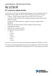
5 Integration of NI-6581 and NI PXIe-7965R in
5.1 DAQ System Design methodology used . . . .
5.1.1 CoreDAQ-Rules . . . . . . . . . . . . .
5.2 Hardware Description . . . . . . . . . . . . . .
5.2.1 NI 6581 I/O Adapter Module . . . . . .
5.2.2 Development and Test Platform . . . .
5.2.3 Final DAQ Architecture for ITER . . .
5.3 Software description . . . . . . . . . . . . . . .
5.4 LabVIEW project . . . . . . . . . . . . . . . .
5.5 Software Layers . . . . . . . . . . . . . . . . . .
5.6 C API . . . . . . . . . . . . . . . . . . . . . . .
5.7 ITER CODAC Maven . . . . . . . . . . . . . .
5.8 Nominal Device Support . . . . . . . . . . . . .
5.9 EPICS IOC . . . . . . . . . . . . . . . . . . . .
5.9.1 IOC Startup File . . . . . . . . . . . . .
5.9.2 EPICS database . . . . . . . . . . . . .
5.9.3 Device and Channels of the IOC . . . .
5.10 The Channel Access Operator Interface Client .
.
.
.
.
.
.
.
.
.
.
.
.
.
.
.
.
.
.
.
.
.
.
.
.
.
.
.
.
.
.
.
.
.
.
.
.
.
.
.
.
.
.
.
.
.
.
.
.
.
.
.
.
.
.
.
.
.
.
.
.
.
.
.
.
.
.
.
.
.
.
.
.
.
.
.
.
.
.
.
.
.
.
.
.
.
.
.
.
.
.
.
.
.
.
.
.
.
.
.
.
CODAC
. . . . . .
. . . . . .
. . . . . .
. . . . . .
. . . . . .
. . . . . .
. . . . . .
. . . . . .
. . . . . .
. . . . . .
. . . . . .
. . . . . .
. . . . . .
. . . . . .
. . . . . .
. . . . . .
. . . . . .
.
.
.
.
.
.
.
.
.
.
.
.
.
.
.
.
.
.
.
.
.
.
16
16
18
18
18
18
19
19
19
20
20
.
.
.
.
.
.
.
.
.
23
23
24
25
26
26
27
27
27
28
Core System
. . . . . . . . .
. . . . . . . . .
. . . . . . . . .
. . . . . . . . .
. . . . . . . . .
. . . . . . . . .
. . . . . . . . .
. . . . . . . . .
. . . . . . . . .
. . . . . . . . .
. . . . . . . . .
. . . . . . . . .
. . . . . . . . .
. . . . . . . . .
. . . . . . . . .
. . . . . . . . .
. . . . . . . . .
31
31
32
34
34
35
35
35
38
41
42
44
46
49
49
50
51
55
.
.
.
.
.
.
.
.
.
.
.
.
.
.
.
.
.
.
.
.
.
.
.
.
.
.
.
.
.
.
.
.
.
.
.
.
.
.
.
.
.
.
.
.
.
.
.
.
.
.
.
.
.
.
.
.
.
.
.
.
.
.
.
.
.
.
.
.
.
.
.
.
.
.
.
.
.
.
.
.
.
.
.
.
.
.
.
.
.
.
.
.
.
.
.
.
.
.
.
.
.
.
.
.
.
.
.
.
.
.
.
.
.
.
.
.
.
.
.
.
.
.
.
.
.
.
.
.
.
.
.
.
.
.
.
.
.
.
.
.
.
.
.
.
.
.
.
.
.
6 Results
57
6.1 Conclusions . . . . . . . . . . . . . . . . . . . . . . . . . . . . . . . . . . . 57
6.2 Future Work . . . . . . . . . . . . . . . . . . . . . . . . . . . . . . . . . . 59
List of Figures
2.1
2.2
Experimental Physics and Industrial Control System Logo . . . . . . . . . 5
Generic IOC Exploited View in the Channel Access Network . . . . . . . 11
3.1
3.2
3.3
Physical Architecture of ITER I&C System. . . . . . . . . . . . . . . . . . 14
Fast Controller in the ITER I&C System for PCIe technology. . . . . . . . 16
Fast Controller Physical Architecture Scheme. . . . . . . . . . . . . . . . . 17
4.1
4.2
4.3
4.4
Scheme of the elements of a FPGA [2] . . . . . .
Configurable Logic Block Structural Scheme [3] .
NI FlexRIO Architecture Diagram [4] . . . . . .
LabVIEW FPGA While Loop with each function
clock period of the system. Extracted from [5] . .
LabVIEW FPGA Single-Cycle Timed Loop,Tclk
the system. Extracted from [5] . . . . . . . . . .
4.5
5.1
5.2
5.3
5.4
5.5
5.6
5.7
5.8
5.9
5.10
5.11
. . . . . . . . . . . . .
. . . . . . . . . . . . .
. . . . . . . . . . . . .
registered ,Tclk is the
. . . . . . . . . . . . .
is the clock period of
. . . . . . . . . . . . .
. 23
. 24
. 26
. 29
. 30
Main schema of the design cycle workflow. Adapted from Sanz et al. [1] .
NI 6581 Adapter Module Specifications table, extracted from [6] . . . . .
Local tests’ architecture . . . . . . . . . . . . . . . . . . . . . . . . . . . .
Final architecture . . . . . . . . . . . . . . . . . . . . . . . . . . . . . . . .
DMA engine mechansim in RIO technology. Extracted from [5] . . . . . .
Local Architecture With flux . . . . . . . . . . . . . . . . . . . . . . . . .
Final Architecture With Data Flux . . . . . . . . . . . . . . . . . . . . . .
LabVIEW Multi-target FPGA Project . . . . . . . . . . . . . . . . . . . .
Automata of the hardware behaviour implemented in the PXIe7965R FPGA
Hardware implemented in the PXIe7965R FPGA . . . . . . . . . . . . . .
Software layers of the EPICS driver developed. Yellow coloured boxes
correpond to parts of the ndsRIO driver. Figure based on [7]. . . . . . . .
5.12 Data Acquisition Software State Machine. . . . . . . . . . . . . . . . . . .
5.13 Operator Interface of the system. . . . . . . . . . . . . . . . . . . . . . . .
ix
33
34
35
36
37
37
38
39
40
40
41
52
56
List of Tables
4.1
4.2
NI FlexRIO Cards [8] . . . . . . . . . . . . . . . . . . . . . . . . . . . . . 27
NI FlexRIO Adapter Modules [9] . . . . . . . . . . . . . . . . . . . . . . 28
6.1
6.2
6.3
6.4
6.5
Report
Report
Report
Report
Report
of
of
of
of
of
the
the
the
the
the
estimated
estimated
estimated
estimated
estimated
device utilization at pre-synthesis . . .
device utilization at synthesis . . . . .
device utilization at mapping . . . . .
timing performance at mapping . . . .
timing performance at place and route
xi
.
.
.
.
.
.
.
.
.
.
.
.
.
.
.
.
.
.
.
.
.
.
.
.
.
.
.
.
.
.
57
57
57
58
58
Listings
5.1
5.2
5.3
5.4
5.5
5.6
5.7
5.8
5.9
5.10
6.1
C header file example generated from an FPGA VI by C API Generator .
Creation of the main skeleton of the EPICS driver . . . . . . . . . . . . .
EPICS driver tree before compilation . . . . . . . . . . . . . . . . . . . . .
Compilation Maven command . . . . . . . . . . . . . . . . . . . . . . . . .
EPICS driver tree after compilation . . . . . . . . . . . . . . . . . . . . .
Creation of the device and its channels . . . . . . . . . . . . . . . . . . . .
EPICS Database directory . . . . . . . . . . . . . . . . . . . . . . . . . . .
EPICS Database directory . . . . . . . . . . . . . . . . . . . . . . . . . . .
Extract of Device Code Digital Input Channel Group and Channels creation
Acquisition Handle Implemented in Digital Input Channel Group . . . . .
Resumed tree of the directories for the DAQ system device support . . . .
xiii
42
45
45
46
47
49
50
51
53
53
58
Abbreviations
ASIC
Application Specific Integrated Circuit
ATCA
Advanced Telecommunications Computing Architecture
CA
Channel Access
CAC
Channel Access Client
CAS
Channel Access Server
CAS
Control Breakdown Structure
CCS
CODAC, Core System
CERN
(fr.) Conseil Européen pour la Recherche Nucléaire
CLB
Configurable Logic Block
CODAC
Control, Data Access and Communication
CSS
Control, System Studio
DAN
Data Archive Network
DMA
Direct Memory Access
EPICS
Experimental, Physics and Industrial Control System
F4E
Fusion for Energy
GPIB
General Purpose Instrumentation Bus
HDL
Hardware Description Laguages
HLS
High-Level Synthesis
HMI
Human-Machine Interface
I&C
Instrumentation & Control
IOC
Input/Output Controller
ITER
International Thermonuclear Experimental Reactor
LHC
Large Hadron Collider
NI
National Instruments
NIC
Network Insterface Card
xv
Abbreviations
xvi
OPI
Operator Interface
PCF
Plant Breakdown Structure
PCDH
Plant Control Design Handbook
PCF
Plant Cotroller Fast
PCI
Peripheral Component Interconnect
PCIe
PCI express
PICMG
PCI Industrial Computer Manufacturers Group
PLC
Programmable Logic Controller
PON
Plant Operation Network
PSH
Plant System Host
PV
Process Variable
PXI
PCI eXtensions for Instrumentation
RCP
Rich Client Platform
RHEL
Red Hat Enterprise Linux
RTOS
Real Time Operating System
SCTL
Single-Cycle Timed Loop
SDN
Synchronous Databus Network
SoC
System on Chip
Dedicated to Rebeca, Jorge, Pilar and Clara
xvii
Chapter 1
ITER, the experiment
1.1
The Organization and the project
Internationa Thermonuclear Experimental Reactor (ITER) is an international research
and engineering international project with the intention to proof the viability of fusion
as commercial energy source. The scientific goal of the ITER project is to deliver ten
times the power it consumes. The consortium, formed by China, the European Union,
India, Japan, Korea, Russia and the United States, is officially signed on 21th November
2006 and assuming the cost the theoretical ten-year construction stage and twenty-year
operational stage.
The members are organized locally in Domestic Agencies, in the case of Europe the
agency in charge is Fusion for Energy (F4E), to act as a nexus between their governments
and the ITER Organization, located adjacent to CEA Cadarache research center in Saint
Paul-lez-Durance, France.
1.2
The Science
As said previously ITER’s final objective is to provide the mankind a cleaner, safer
and unlimited source of energy. In fusion reactions lighter atomic nuclei fuse to form a
heavier nucleus releasing a large amount of energy.
The most efficient fusion reaction to produce in a laboratory is the reaction between
two hydrogen isotopes, deuterium and tritium producing the highest gain of energy at
the lowest temperatures compared with other elements, requiring 150 Million degrees
Celsius to produce.
1
Chapter 1. ITER, the experiment
2
In ITER, the fusion reaction will be achieved in a tokamak device that uses magnetic
fields to contain and control the plasma. The helium nucleus carries an electric charge
which will respond to the magnetic fields of the tokamak and remain confined within
the plasma. However, some 80 percent of the energy produced is carried away from
the plasma by the neutron which has no electrical charge and is therefore unaffected by
magnetic fields. The neutrons will be absorbed by the surrounding walls of the tokamak,
transferring their energy to the walls as heat, the heat will be used to produce steam
and electricity by way of turbines and alternators.
1.3
The Machine
The plasma will be confined by magnets in a torus hermetically-sealed steel container,
named vacuum vessel, holds the fusion reaction. In order for the gas to reach the plasma
state three external heating sources. The ITER magnets will be cooled at 4 K in order
to create the magnetic fields necessary for the plasma confinement, that temperature
will be created by an external cryogenic system, after the Large Hadron Collider (LHC)
at Conseil Européen pour la Recherche Nucléaire (CERN) -french acronym of European
Council for Nuclear Research- it will be the largest cryogenic system ever built.
An extensive diagnostic system will be installed on the ITER machine to provide the
measurements necessary to control, evaluate and optimize the performance of the experiment and to further the understanding of plasma physics. This include measurements
of temperature, density, impurity concentration, and particle and energy confinement
times. The diagnostic system will comprise modern techniques including lasers, X-rays,
neutron cameras, impurity monitors, particle spectrometers, radiation bolometers, pressure and gas analysis, and optical fibres. Because of the harsh environment inside the
vacuum vessel, these systems will have to cope with a range of phenomena with great
accuracy and precision.
Control, Data Access and Communication (CODAC) is the central control system responsible for operating the ITER device. CODAC interfaces to more than 30 ITER plant
systems containing actuators, sensors and local Instrumentation and Control (I&C). For
the machine protection, interlock system and safety (personnel and environment) systems, are explicitly decoupled from CODAC and act fully independently. Control System
Division, incharge of aforementioned tasks, is also responsible for the central interlock
system and central safety system. CODAC Core System (CCS) is the operating system
for ITER and is based on Experimental, Physics and Industrial Control System (EPICS)
and Control System Studio (CSS). Users who contribute to the development of ITER
Chapter 1. ITER, the experiment
3
I&C System, such as ITER Domestic Agencies or industries working for ITER through
contracts, uses CODAC and dedicated software distribution.
1.4
Document Outline
What the reader is going to find in the next sections is an example of an EPICS driver
for reconfigurable hardware based on FlexRIO technology.
This driver is created following given LabVIEW FPGA design rules and using an EPICS
driver able to find itself the resources and functionalities found in the FPGA at runtime
as proposed by Sanz et al. [1]. To create the EPICS Device Support the Nominal
Device Support common interface is used and documented as use case for later and
more complex developments. As an interface to the driver an EPICS client BOY panel
is provided.
The hardware architecture is composed by FlexRIO devices in PXIe chassis and a host
computer connected to the chassis by a PCIe expansion link detailed afterwards.
1.4.1
Content
• Chapter 1: Global framework and introduction to the thesis topic
• Chapter 2: EPICS, the basis
• Chapter 3: ITER’s Control, Data Access and Communication
• Chapter 4: National Instrument’s FPGA-based FlexRIO devices
• Chapter 5: Integration of NI-6581 and NI PXIe-7965R in CODAC Core System
• Chapter 6: Results Obtained
Chapter 2
EPICS
2.1
Introduction to EPICS
EPICS is an open-source distributed control system toolkit that consists of a set of software tools and applications which provide a software infrastructure that application
developers can use for building distributed control systems to operate devices such as
Particle Accelerators, Large Experiments and major Telescopes. Such distributed control systems typically comprise a large amount of computers, networked together to allow
communication among them and to provide control and feedback of the various parts of
the device from a central control room, or even remotely over the internet EPICS uses
a network-based client/server model. Large scale scientific applications often require
hundreds of devices to communicate over a single network to form large distributed control systems. EPICS provides the standards and tools necessary to make this kind of
communication possible.
Figure 2.1: Experimental Physics and Industrial Control System Logo
The EPICS logo, figure 2.1, represents the main idea of EPICS, each coloured box
represents a client or a server connected through a network. For EPICS, the Channel
5
Chapter 2. EPICS
6
Access (CA) role can be Channel Access Client (CAC) or Channel Access Server (CAS),
CACs are programs that require access to the Process Variables to carry out their
purpose and the service provided by Channel Access Servers is the access to Process
Variables.
This chapter describes the main components: the variables exchanged between clients
and servers (Process Variables 2.2), the element that manipulates this variables (Input
Output Controllers 2.3), backbone of the control network (CA protocol 2.4) and some
tools used to monitor archive and edit these exchanged variables (2.6).
2.2
Process Variable
Process Variables (PVs), in the CODAC context often used in a narrower sense of EPICS
PV, are EPICS variables that are exchanged between servers and clients and are defined
by EPICS records in the EPICS Database. A process variable can give a computerised
representation of a plant signal.
EPICS database is a process database running on a CAS, also known as the Input
Output Controller (IOC), this database consists of records which represent data points
of control system. Records consists of number of attributes (fields) and code that defines
the records’ behaviour when active.
Most EPICS applications require only basic record types such as:
• ai, ao: Analog input/output
• bi, bo: Binary input/output
• longin, longout: Long integer value input/output
• mbbi, mbbo: Multi-bit binary input/output
• stringin, stringout: String input/output
• calc: Record that performs algebraic, relational and logical operation
• waveform: Data in arrays.
Records can be connected among each other to exchange information and can be connected to hardware devices. Records can define database links to:
• Exchange data among each other (records connected among each other).
Chapter 2. EPICS
7
• Implement closed loop control.
• Records can connect to hardware devices and/or other records.
The IOC database manages Records. A Record has Fields, for instance a particular an
analog input record can have fields such as
• VAL (value)
• EGU (Engineering Units)
• TIME (Timestamp)
• HOPR (High Operator Range)
• LOPR (Low Operator Range)
• STAT (Alarm Status)
• SEVR (Alarm Severity)
The database (.db) file can be used to get and set the contents of the fields of a record.
These values and attributes of Process Variables are defined by the CA Servers. The
Channel Access network protocol gives access to Channels. A particular Channel has
properties such as: value, time stamp, units, upper control limit, lower control limit,
status, and severity.
Main element’s definition:
• A Process Variable: Typed structure according to a record type and the inputs, data manipulation and outputs are defined by EPICS records in the EPICS
Database. These EPICS variables are exchanged between servers and clients.
a PV is a typed structure according to a record type (like binary input, binary
output, analog input, analog output, calculation ...) and the inputs, data manipulation and outputs are defined by configuring each record
• A Record Type: Predefined building block with a unique structure of fields and a
unique processing routine to accomplish a specific function.
• Record support: Refers to a processing routine and the definition of the structure
(i.e. an analog input record is used to monitor an analog signal, convert it to engineering units, check the value against alarm limits, and notify interested channel
access clients of any significant change).
Chapter 2. EPICS
8
• Record: A particular instance of a Record Type with appropriate values entered
into the relevant fields.
• Database: A collection of records.
• Scanned (processed): Executing the record processing routine (unique to a record
type) for a particular record
2.3
The Input Output Controller
The EPICS software processes are called IOCs. The main responsibility of the EPICS
Input/Output Controller (IOC) is to input data from the local process (and/or the
operator), manipulate/convert/compute it, update the PV value time-stamp and alarm
status/severity and optionally output data to the local control process.
EPICS PVs become part of an IOC’s database. The IOC scans the database, deciding
when and how to process a predefined record. IOCs can run in the same environment as
which it was compiled or can run in a different environment that where compiled using
cross software development tools.
An IOC contains the following software components
• The IOC Database: The main element of an IOC is a database together with some
structures that describe the contents of the database (the first field of a database
record contains the record name).
• Database access routines via channel or database access routines.
• Mechanisms for deciding when to process a record (Scanners):
– Periodic: To process a record periodically, standard scan rates are: 10, 5, 2,
1, 0.5, 0.2 and 0.1 seconds and custom scan rates can be configured up to
speeds allowed by operating system and hardware
– Event driven: Events request from another record via links, EPICS Events
and Channel Access Puts.
– I/O Event: processing records based on external interrupts.
– Passive: records are processed as a result of linked records being processed
or as a result of external changes such as Channel Access puts.
– Scan Once: Makes a record to be processed one time.
Chapter 2. EPICS
9
• Record support routines, device support routines and device drivers for accessing
to external devices for each record. Record types not associated with hardware do
not have device support or device drivers.
• The interface between the external world and the IOC via Channel Access.
• Database monitors provide a callback mechanism for database value changes. This
allows the caller to be notified when database values change without constantly
polling the database.
• Tools to implement state machines (Sequencer)
The IOC Core consists of the core software of EPICS that EPICS would not run without,
that are: Channel Access, IOC Database, Scanners, Monitors, Database Definition Tools
and Source/Release folders containing the raw code and the compiled code respectively.
2.4
The Channel Access
The Channel Access Protocol is a client-server TCP/IP-based communication protocol of
EPICS. The protocol defines how Process Variable data is transferred between a server
and client in any IOC database and also ensures an interface between the CODAC
central control system and the local control systems. Each IOC provides a Channel
Access Server which is prepared to establish communication with an arbitrary number
of Channel Access Clients.
The main benefits of the CA are:
- Provides transparency from the Operating System
- Network transparency (equal access to remote and local channels)
- CPU architecture independence, isolation from software changes
The software architecture paradigm is based on a publish/subscribe messaging throughout the control network. The requests are based on the PV name and that requests
include Search, Get, Put and Add Event methods.
2.5
Device Support
Device support is the interface between record and the hardware, it hides hardware
specific details from record processing routines. Device support routines are the interface
Chapter 2. EPICS
10
between hardware specific fields in a database record and device drivers or the hardware
itself.
Device support modules can be divided into two basic classes: synchronous and asynchronous. Synchronous device support is used for hardware that can be accessed without
delays for I/O. Many register based devices are synchronous devices. Other devices, for
example all General-Purpose Instrumentation Bus (GPIB) devices, can only be accessed
via I/O requests that may take large amounts of time to complete. Such devices must
have associated asynchronous device support. Asynchronous device support makes it
more difficult to create databases that have linked records.
2.6
Tools, alarms, archiver and EPICS Clients
EPICS version 3.14 provides a number of Operator Interface (OPI) based tools that can
be divided into two groups based on whether or not they use Channel Access. (Channel
Access tools are real time tools, i.e. they are used to monitor and control IOCs.)
• Channel Access Tools
Display Managers like EDM/MEDM read one or more display list files created by
the Display Editor, establishes communication with all necessary IOCs, establishes
monitors on process variables, accepts operator control requests, and updates the
display to reflect all changes. Alarm handlers, archivers and probes allows the user
to monitor and/or change a single process variable specified at run time.
• Other OPI tools
– Database configuration tools like VDCT/JDCT/GDCT
– Display editor EDD used to create a display list file for the Display Manager.
– State Notation Compiler that generates a C program representing the states
for the IOC Sequencer tool.
The graphic 2.2 depict the environment of the Channel Access network with some elements suscribed as CACs and CASs. Exemplifying five generic elements in the network
(coloured boxes) and a the description of the elements within a generic IOC (gray box).
MEDM (yellow box) is a display manager/editor for EPICS, LabView (red box) acts
as Process Variable publisher/subscriber, My Data Collection Program (blue box) is
Channel Access Client implementing a program, iocCore (green box) is an IOC without
any connection to hardware, Simulator Code (dark yellow box) acts as a Process Variable
Server in the network and the IOC (gray box) showing its internal structure.
Chapter 2. EPICS
11
LabView
(PVs)
MEDM
CAC
CAS
CAC
My Data
Collection
Program
CAC
ioc Core
(PVs)
CAS
CAC
Channel Access
IOC
Channel Access
Server
CAS
Channel Access
Client
Simulator
Code
(PVs)
Sequencer
Scanners
Database
Access
Library
Monitors
IOC Database
Driver or
Device
Interrupt
Routines
Database
Library
Record Support
Device Support
Device
Drivers
Instrumentation and
control hardware
Figure 2.2: Generic IOC Exploited View in the Channel Access Network
Chapter 3
ITER’s CODAC
3.1
Control, Data Access and Communication
As introduced in section 1.3 CODAC designates the central control system that operates
in ITER. The CODAC Core System is a software package that is distributed by CODAC
Section of ITER Organization for the development of the Plant System I&C. It includes
the software for Mini-CODAC, Plant System Host (PSH) and Plant Controllers Fast
(PCF) and it provides the plant system I&C developers the environment required to
develop and test the software satisfying the ITER requirements.
The operating system for Mini-CODAC, PSH and PCF is an officially supported version
of Red Hat Enterprise Linux (RHEL). The EPICS base is included in the distribution
and is required for Mini-CODAC, PSH and PCF. The EPICS framework is the base for
the Fast Controllers and PSH, and the EPICS CA protocol for access to plant system
I&C over the Plant Operation Network (PON).
The ITER project is broken down into plant systems, known as the Plant Breakdown
Structure (PBS). The plants have specific functional requirements, each requirement has
to be treated separately with its own I&C System called Plant System I&C. In order
to facilitate integration and control, CODAC has a functional categorization named
Control Breakdown Structure. Plant System I&Cs are grouped into hierarchical control
groups. Each of these control groups can have a number of servers dedicated to runtime
activities such as archiving, control group management and configuration management
for the control group.
Figure 3.1 illustrates the physical architecture of the ITER I&C system. A plant system
includes a set of controllers with a PSH implementing a set of functions. A control group
is an assembly of plan system I&Cs and central coordination.
13
Chapter 3. ITER’s CODAC
14
Figure 3.1: Physical Architecture of ITER I&C System.
In the following sections the most capital pieces of CODAC and the important parts for
the document scope are described giving an outline for the subsequent chapters.
3.2
Plant System I&C Design
ITER I&C System wrap all hardware and software required to operate the ITER machine, it comprises plant systems I&C, Central I&C Systems and I&C Networks. Some
entities have to be defined to understand the Instrumentation and Control architecture
seen in figure 3.1.
• A Plant System I&C can be defined as all hardware and software required
to control a plant system including local protection and safety functions. Plant
System I&C encloses Plant Control System, Plant Interlock System and Plant
Safety Systems. It has one plant system host and an arbitrary number of controllers
called control units. Controllers are divided into slow and fast depending on the
process’ characteristics determining different technologies used for implementation,
PLCs for slow processes and Linux based-computers running EPICS with PCI/PXI
I/O for fast processes. Slow controllers are programmed with Siemens SIMATIC
STEP 7 and PCF and PSH are configured using EPICS tools under RHEL.
Chapter 3. ITER’s CODAC
15
Each plant system I&C implements one or many functions. For each function
the variables and commands have to be declared to operate in CODAC. Each
functional variable is instantiated by one control unit and maps directly to one
EPICS Process Variable; if the control unit is a PLC, to one program variable in
a PLC.
• Central I&C Systems All hardware and software required to coordinate all
plant systems I&C, including protection and safety functions and to provide the
human-machine interface (HMI). It comprises the CODAC System, Central Interlock System and Central Safety Systems.
– Central Interlock System (CIS) Provides protection functions from material damage which would result insignificant cost or schedule implications.
Communicates with Plant Interlock Systems using Central Interlock Network.
Provides status to CODAC System.
– Central Safety Systems (CSS) Provide plant-wide nuclear and occupational safety functions. Communicate with Plant Safety Systems using Central Safety Network. Provide status to Central Interlock System and CODAC
System.
• I&C Networks Provide physical interface between Central I&C Systems and
plant systems I&C. Comprises CODAC Networks, Central Interlock Network and
Central Safety Networks.
• I&C Plant Control System Provides local data acquisition, control, monitoring, alarm handling, logging, event handling and data communication functions.
Communicates with CODAC System using CODAC Networks. Comprises Plant
System Host and plant system controller(s).
– Plant System Host Provides asynchronous communication from CODAC
System to Plant Control System and vice versa. Provides command dispatching, state monitoring, data flow and configuration functions.
– Plant System Controller Provides plant system specific data acquisition,
control, monitoring, alarm handling, logging and event handling functions.
Interfaces the Central I&C systems through I&C networks and plant system
equipment through signals and fieldbuses.
– Plant Interlock System (PIS) Provides Investment Protection functions
for plant system. Interfaces to Central Interlock System.
– Plant Safety Systems (PSS) Provide Safety functions for plant system.
Interfaces to Central Safety Systems.
Chapter 3. ITER’s CODAC
3.3
3.3.1
16
Hardware Components
Slow Controllers
The term Slow Control is used for controllers that their reactivity is extremely slow in
comparison to acquisition systems dedicated to the observation of the experiment. They
are in charge of the industrial services of the experiment that are not expected to change
fast, like vacuums, cooling and control loops, providing a control loop performance of
100 Hz or less. Via a network connection to the controller, they are programmed with
STEP-7 engineering software from a Windows development system. The PLCs will
communicate with CODAC through the PSH,it’s configuration will be generated for
each Plant System I&C. The communication with STEP-7 PLCs will be done through
TCP/IP Socket communication.
3.3.2
Fast Controllers
A fast controller is a control system component defined as a plant system controller
used to implement control loops or data acquisition in Plant System Instrumentation &
Control at a rate faster than 100 Hz. In the current design it is implemented using PXI
Express, ATCA or uTCA based solutions, the first ones to carry the I/O boards and
the last one proposed for diagnostics. Figure 3.2 maps the fast controller in the ITER
Plant System I&C .
Figure 3.2: Fast Controller in the ITER I&C System for PCIe technology.
The intended capabilities for a PCF are:
Chapter 3. ITER’s CODAC
17
• Data acquisition with accurate time stamping
• Actuation with precise timing
• Real-time exchange of data with other systems
• Locally closed control loops in hard real-time
In the specific case of the PXIe, the chassis is separated from the CPU standard industrial
computer and interconnected using a PCIe link. As depicted in figure 3.3 the fast
contolled is composed by an industrial PC with two separated Network Interface Cards
(NIC) one for Data Archive Network (DAN) and Synchronous Databus Network (SDN)
and the other for the Plant Operation Network (PON). All the hardware metioned for
the PCF is integrated in a single I/C Cubicle. The link to the PXIe chassis is with a
PCIe-PXIe bridge. The PXIe chassis will be covered in detail in chapter 4 and 5 since
the Fast Controller is the target hardware for the DAQ system designed.
Fast Controller
Industrial PC
CPU #1
CPU #2
Hard disk
RAM
ATA
controller
PCI Express bus
PCI Express – PXIe “bridge”
(NI PCIe-8361 / MXI-Express)
1Gbps
Ethernet NIC
10Gbps
Ethernet NIC
PON
SDN
SDN
DAN
PXI Chassis (18-Slot 3U NI PXIe-1065)
PCI Express – PXIe “bridge”
(NI PXIe-8361 / MXI-Express)
Timing module
(NI PXI-6682)
TCN
PXIe bus: PXI (9x), hybrid (4x), PXIe (3x), PXIe timing (1x)
General-purpose
A/D I/O
(NI PXI-6259)
Signal concentrator
… total of 22 connectors ...
Signal concentrator
… total of 22 connectors ...
Figure 3.3: Fast Controller Physical Architecture Scheme.
Chapter 3. ITER’s CODAC
3.3.3
18
Plant System Host
The plant System Host is a system that is part of a plant system I&C and is supplied
and maintained by CODAC. In the I& C integration kits, the PSH is configured in
a computer that will be installed in one of the I&C cubicles. Each PSH belongs to
one plant system I&C, it is connected to the PON network and belongs to the same
sub-network as the other controllers of the same I&C.
The PSH has no I/O board and cannot interface to any hardware. It provides command
dispatching, state monitoring, overall coordination, health monitoring, and, optionally,
communication with slow controllers. Each plant system I&C can only have one PSH.
3.3.4
CODAC Terminal
A CODAC terminal is an operation station providing I/O to/from an operator through
the human machine interface (HMI). CODAC terminals are close to local plant system equipment for integration, commissioning, troubleshooting and maintenance of that
equipment. Control Room CODAC terminals use software deployed and configured using the CODAC Core System.
3.3.5
CODAC Server
A central CODAC server is a standard server-class computer running either CODAC
run-time applications or CODAC support services. Run-time server applications include
common EPICS applications such as archiving and alarm handling and common sitespecific applications, including plant wide supervision, monitoring and control, global
operational state management and interfaces to the CIS and CSS. In addition, CODAC
servers run special applications such as pulse scheduling and scientific data archiving.
CODAC support services include directory services, software download to plant systems
and software configuration management.
3.3.6
Storage Systems
There are several storage categories attending to different functionalities such as the
reliability, high availability and high degree of integration with the servers; other used
for the CODAC System database services like alarms and error logs; and other accomplishing requirements to evacuate data in quasi-real-time for visualisation and for long
term archiving.
Chapter 3. ITER’s CODAC
3.3.7
19
I/O Boards
I/O boards are important components for CODAC. A controller supervises one or many
I/O boards. Each I/O board has a set of channels that can be associated with plant system signals, and can be used to generate the I/O configuration data for fast controllers.
There are a limited number of I/O boards in the ITER Catalogue For Fast Controllers
[10]. The ITER standard Fast Controller catalogue describes the hardware accepted to
be part of the experiment.
3.4
CODAC software tools
3.4.1
Self-Description Data toolkit
Self-Description Data (SDD) is an ITER concept designating the static data that describes the plant system characteristics in a unified way in order to facilitate configuration of the Central I&C systems’ software for operation with the given plant system.
The SDD tool-kit has been developed by ITER Organization in order to allow the user
to configure the plant system I&C and is a set of tools to support top-down configuration
and the programming of I&C components.
SDD is part of the CODAC Core System. The data created is then used to configure
and program underlying Plant System I&C hardware and software.This includes:
• The SDD Editor to define the plant system interface, the I&C components, the
interfaced signals and to configure variables, alarms, archiving, etc. The editor is
an Eclipse Rich Client Platform (RCP) application.
• The SDD translator to convert the SDD into the required EPICS configuration
data for Mini-CODAC, PSH and fast controllers and into the required STEP-7
files for PLCs.
• The SDD sync tool to save and loading SDD data to/from XML files and to
synchronize local SDD databases with IO databases as well as local files with the
IO source repository.
• The SDD parser to parse user provided or user modified EPICS configuration files
(EPICS record definition) and retrofit changes into the SDD database.
The SDD tools provide the user with creation, editing and saving features for:
Chapter 3. ITER’s CODAC
20
• The list of signals interfaced by the plant system I&C, list of functions and variables implemented by the plant system I&C and the list of control units (PSH,
controllers) that belongs to the plant system I&C
• The communication between PSH and PLC.
• The configuration for alarms, archiving, HMIs, for the supported I/O boards and
the cubicles that shall be monitored (from 4.0).
• The mapping of Common Operating State variables into plant-system specific ones
(from 4.0)
3.4.2
Control System Studio
Control System Studio (CSS) is part of CODAC Core System and is a collection of
software built on Eclipse that provide an application framework for control systems.
Operator interface, data archiving and monitoring, alarm handling and data plots can
be configured. The CSS applications connect themselves to the IOC processes using
EPICS Channel Access protocol.
CCS comes with an integrated tool to support the CODAC I&C development life cycle:
create, compile, run and package I& C applications.
3.4.3
Maven Editor
The CODAC build tool is an ITER’s proprietary version of Apache Maven, a software
build automation framework.
All the EPICS development tools described in EPICS Application Developer’s Guide [11]
are valid but all of them are included in CODAC encapsulated within specific commands.
I&C projects are developed using an ITER specific work flow that is supported by the
SDD tools and by commands implemented using Maven.
The CODAC development work flow comprises:
1. Creation of the I&C project with the SDD Editor or SDD web application.
2. Generation of the EPICS/CSS/STEP-7 configuration files with the SDD translator.
3. Creation/update of the software unit with dedicated commands. The sequence of
calls is produced by the SDD translator, according to the I&C project definition.
Chapter 3. ITER’s CODAC
21
4. Edition of user-defined files with test editor or specific editors, such as the CSS
SNL editor and VDCT.
5. Compilation of the EPICS IOC processes and of the real-time programs with the
Maven compile command.
6. Test of the project with the start, stop, status and test commands.
7. Creation of the software packages for distribution with the package command.
As described in CODAC Plant Control Design Handbook [12]. The graphical tool,
maven-editor, provides the user a graphical HMI for executing the commands. This is
also integrated in SDD tools so user can build/test/package the applications from the
SDD editor or the SDD web application.
Chapter 4
National Instruments’ FlexRIO
Technology
4.1
Brief FPGA basis
Field Programmable Gate Arrays (FPGAs) are programmable semiconductor devices
that are based around a matrix of Configurable Logic Blocks (CLBs) connected through
programmable interconnections. As opposed to Application Specific Integrated Circuits
(ASICs), where the device is custom built for the particular design, FPGAs can be
programmed to the desired application or functionality requirements. Although OneTime Programmable (OTP) FPGAs are available. The common type of FPGAs are
SRAM-based which the modelled hardware hosted can be changed as the design evolves.
Figure 4.1 depicts the main elements which the FPGA is composed by.
Figure 4.1: Scheme of the elements of a FPGA [2]
23
Chapter 4. National Instruments’ FlexRIO Devices
24
The configurable logic blocks (CLBs), slices or logic cells, -depicted in figure 4.2- are the
basic logic unit of an FPGA. They are made up of: a configurable switch matrix with
4 or 6 inputs, some selection circuitry, like multiplexers, and flip-flops. Various FPGA
families differ in the way flip-flops and LUTs are packaged together.The switch matrix
is highly flexible and can be configured to handle combinatorial logic, shift registers or
RAM.
Figure 4.2: Configurable Logic Block Structural Scheme [3]
The flexible interconnection of the FPGA routes the signals between CLBs and I/Os.
There are different types of routing, from the interconnection between CLBs to fast
horizontal and vertical lines crossing the device to global low-skew routing for clocking
and other global signals. The design software makes the interconnect routing task hidden
to the user, unless necessity, significantly reducing design complexity. I/Os in FPGAs are
grouped in banks with each bank independently able to support different I/O standards.
Today’s FPGAs provide over a dozen I/O banks, thus allowing flexibility in I/O support.
Embedded Block RAM memory is available in most FPGAs, which allows for on-chip
memory in your design. Digital clock management is provided by most FPGAs in the
industry and also phase-looped locking that provide precision clock synthesis combined
with jitter reduction and filtering.
Memory resources are another key specification to consider when selecting FPGAs. Depending on the FPGA family the on-board RAM can be configured in different block
sizes. Digital signal processing algorithms often need to keep track of an entire block
of data, or the coefficients of a complex equation, and without on-board memory, many
processing functions do not fit within the configurable logic of a FPGA chip.
4.2
FPGA Design Tools
The way to build the logic that will be placed in the FPGA is modelling the behaviour of
the system using development tools and then compile them down to a configuration file
Chapter 4. National Instruments’ FlexRIO Devices
25
or bitstream that contains information on how the components should be wired together.
Hardware description languages (HDLs) such as VHDL and Verilog are textual languages for architecting a circuit.The syntax requires signals to be mapped or connected
from external I/O ports to internal signals, which ultimately are wired to the modelled
hardware entities. However, the modelled hardware behaviour is hard to be visualized
in a sequential line-by-line flow textual language.
To then verify the logic created, it is common practice to write test benches in HDL to
wrap around and exercise the FPGA design by asserting inputs and verifying outputs.
The test bench and FPGA code are run in a simulation environment that models the
hardware timing behaviour of the FPGA chip and displays all of the input and output
signals to the designer for test validation. The process of creating the HDL test bench
and executing the simulation requires at least four times more than creating the original
FPGA HDL design itself.
Once verified the text-based model of the hardware through several steps, synthesizes
the HDL down into a configuration file or bitstream that contains information on how
the components should be wired together. As part of this multi-step process, a mapping
of signal names to the pins on the FPGA chip have to be done.
The rise of high-level synthesis (HLS) design tools, such as NI LabVIEW system design software, changes the rules of FPGA modelling and delivers new technologies that
convert graphical block diagrams into digital hardware circuitry. The LabVIEW programming environment is suited for FPGA modelling being easier for the designer to
recognize parallelism and data flow. Also VHDL can be integrated into LabVIEW FPGA
designs.
To simulate and verify the behavior of your FPGA logic, LabVIEW offers features
directly in the development environment. LabVIEW FPGA compilation tools automate
the compilation process highlighting errors if occur and critical paths if timing errors
occur to debug the design.
4.3
RIO Platform Architecture
The reconfigurable I/O architecture combines the graphical programming environment
with Processor + a reconfigurable FPGA + I /O Modules for measurement and/or
acquisition, see figure 4.3. The advantages of FPGAs for creating highly customizable
and reconfigurable platforms implementing processing and control tasks with hardware
circuitry and the capacity to perform multiple parallel operations within a single clock
Chapter 4. National Instruments’ FlexRIO Devices
26
cycle. Orchestrate with a processor offloaded by the FPGA and used to configure the
FPGA, interface with other peripherals, log data, run aplications, etc. and I /O Modules
directly connected to the FPGA for interfacing with other devices.
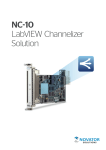
The reconfigurable FPGA is the core of the RIO hardware system architecture, it is
directly connected to the I/O modules for high-performance access to the I/O circuitry of
each module and unlimited timing, triggering, and synchronization flexibility. Because
each module is connected directly to the FPGA rather than through a bus, there is
almost no control latency for system response compared to other industrial controllers.
Figure 4.3: NI FlexRIO Architecture Diagram [4]
4.3.1
RIO for PXIe and a PC
PXI (PCI eXtensions for Instrumentation) is a rugged, modular instrumentation platform designed for high-performance applications. It combines PCI and PCI Express bus
technologies with a specialized synchronization bus.
PXI Express takes advantage of the PCI Express bus to offer a point-to-point bus topology that gives each device its own direct access to the bus with up to 4 GB/s of throughput. The integrated timing and synchronization lines are used to route synchronization
clocks and triggers internally. A PXI chassis incorporates a dedicated 10 MHz system
reference clock, PXI trigger bus, star trigger bus, and slot-to-slot local bus, while a
PXI Express chassis adds a 100 MHz differential system clock, differential signaling, and
differential star triggers for advanced timing and synchronization.
4.3.1.1
FlexRIO
FlexRIO devices consist of a large FPGA, as well as adapter modules that provide
high-performance analog and digital I/O. The adapter modules are interchangeable and
Chapter 4. National Instruments’ FlexRIO Devices
27
Model
Bus
FPGA
FPGA
Slices
FPGA
DSP Slices
FPGA Memory
(Block RAM)
Onboard
Memory
PXIe-7975R
PXIe-7966R
PXIe-7965R
PXIe-7962R
PXIe-7961R
PXI-7954R
PXI-7953R
PXI-7952R
PXI-7951R
PXIe
PXIe
PXIe
PXIe
PXIe
PXI
PXI
PXI
PXI
Kintex-7 XC7K410T
Virtex-5 SX95T -2
Virtex-5 SX95T
Virtex-5 SX50T
Virtex-5 SX50T
Virtex-5 LX110
Virtex-5 LX85
Virtex-5 LX50
Virtex-5 LX30
63,550
14,720
14,720
8,160
8,160
17,280
12,960
7,200
4,800
1,540
640
640
288
288
64
48
48
32
28,620 kbits
8,784 kbits
8,784 kbits
4,752 kbits
4,752 kbits
4,608 kbits
3,456 kbits
1,728 kbits
1,152 kbits
512 MB
512 MB
512 MB
512 MB
0 MB
128 MB
128 MB
128 MB
0 MB
Table 4.1: NI FlexRIO Cards [8]
define the I/O in the LabVIEW FPGA programming environment.
NI FlexRIO FPGA modules feature, as seen in table 4.1, Xilinx Virtex-5 and Kintex7 FPGAs, onboard dynamic RAM (DRAM), and an interface to NI FlexRIO adapter
modules that provide I/O to the FPGA. The adapter module interface consists of 132
lines of general-purpose digital I/O directly connected to FPGA pins, in addition to the
power, clocking, and supplementary circuitry necessary to define the interface.
Adapter modules are instantiated as a part of the LabVIEW project in a ComponentLevel Intelectual Property (CLIP)and the I/O interaction is provided by LabVIEW
interfaces. Table 4.2 shows the full range of adapter modules provided.
4.3.1.2
R Series
Multifunction DAQ boards can measure and generate a wide variety of signals at different sampling rates. R Series multifunction RIO devices integrates FPGA technology
with analog inputs, analog outputs, and digital I/O lines into a single device. This
devices support the PCI, PCI Express, PXI, and USB buses, with enclosed and boardonly options available. Also feature a dedicated ADC per channel, providing multirate
sampling and individual channel triggering.
4.3.2
4.3.2.1
RIO for Compact Embedded Aplications
Compact RIO
CompactRIO is a small, rugged RIO system for embedded and prototyping applications.
Configurable with four- and eight-slot backplanes. It contains three components: a
Chapter 4. National Instruments’ FlexRIO Devices
28
NI 5791 100 MHz Bandwidth RF Transceiver
NI 5792 200 MHz Bandwidth RF Receiver
NI 5793 200 MHz Bandwidth RF Transmitter
NI 5781 100 MS/s Baseband Transceiver
NI 5782 250 MS/s IF Transceiver
NI 5731 12-Bit, 40 MS/s, 2 Channel Digitizer
NI 5732 14-Bit, 80 MS/s, 2 Channel Digitizer
NI 5733 16-Bit, 120 MS/s, 2 Channel Digitizer
NI 5734 16-Bit, 120 MS/s, 4 Channel Digitizer
NI 5751 14-Bit, 50 MS/s,16 Channel Digitizer
NI 5752 12-Bit, 50 MS/s, 32 Channel Digitizer
NI 5761 14-bit, 250 MS/s, 4 Channel Digitizer
NI 5762 16-Bit, 250 MS/s, 2 Channel Digitizer
NI 5771 8-Bit, 3GS/s, 2 Channel Digitizer
NI 5772 12-Bit, 1.6GS/s, 2-Channel Digitizer
AT-1120 14-Bit, 2GS/s, 1-Channel Signal Generator
AT-1212 14-Bit, 1.2GS/s, 2-Channel Signal Generator
NI 6581 200 Mbit/s, 54 Channel, Single Ended Digital I/O
NI 6583 300 Mbit/s, 32 SE and 16 LVDS Channel Digital I/O
NI 6584 16 Mbit/s, 16 Ch, RS-422/RS-485 Digital I/O
NI 6585 200 Mbit/s, 32 Channel, LVDS Digital I/O
NI 6587 1 Gbit/s, 20 Channel, LVDS Digital I/O
NI 1483 Full Configuration Camera Link
Table 4.2: NI FlexRIO Adapter Modules [9]
processor running a real-time operating system (RTOS), a reconfigurable FPGA, and
interchangeable industrial I/O modules.
The CompactRIO system includes an embedded controller and reconfigurable chassis.
The embedded controller can host LabVIEW Real-Time applications and can accomplish
floating-point math and analysis. The embedded chassis contains the reconfigurable I/O
FPGA core directly connected to I/O modules that deliver diverse high-performance I/O
capabilities.
4.4
LabVIEW for FPGA
As mentioned in section 4.2 the use of a HLS design tool like NI LabVIEW leverages
the complexity of the hardware modelled and makes easier the abstraction of following
the dataflow of the modelled hardware. To achieve high performance applications some
specific techniques have to be followed understanding the performance as four different
dimensions interrelated among each other, these are throughput, timing control, FPGA
resource use, and numerical precision as proposed in the NI LabVIEW High-Performance
FPGA Developer’s Guide[5].
Chapter 4. National Instruments’ FlexRIO Devices
29
Most of the issues related to high-performance LabVIEW FPGA modelling involve the
effective use of the Single-Cycle Timed Loop (SCTL). The SCTL is a key LabVIEW
FPGA structure that reduces resource use and allows for higher throughput and more
precise timing control. The SCTL provides a different paradigm compared with a LabVIEW While loop or For loop.
The traditional execution model followed by LabVIEW is called Structured data flow,
where a function must have all of its input parameters before it executes and the caller
blocks until the function returns. The way that LabVIEW FPGA accomplish that, when
translated to hardware, is adding circuitry needed to make sure that the components only
outputs valid data when they have valid data at all of their inputs. This is materialised
connecting every block output to a register.
As depicted in 4.4 red boxes with an R inside symbolises the existent registers that
LabVIEW internally adds for accomplishing its paradigm, with the system pipelined
every clock cycle Tclk the signals are only propagated from one register to the next one.
Tclk
Tclk
Tclk
Figure 4.4: LabVIEW FPGA While Loop with each function registered ,Tclk is the
clock period of the system. Extracted from [5]
In contrast, the SCTL is a structure unique to LabVIEW FPGA applications. The
synthesis of what is placed inside a SCTL differs from While Loop in it is guaranteed
that the signal propagation between combinational blocks - between circuitry- inside it
must not exceed one clock cycle. The one-cycle iteration latency of the SCTL is depicted
in 4.5 where in a single clock cycle Tclk the input signals are propagated to the outputs.
Once the LabVIEW data flow is understood the hardware architect shall follow the
specific techniques for throughput optimization, timing optimization, and resource optimization covered in [5] depending on the design requisites.
Chapter 4. National Instruments’ FlexRIO Devices
30
Tclk
Figure 4.5: LabVIEW FPGA Single-Cycle Timed Loop,Tclk is the clock period of
the system. Extracted from [5]
Chapter 5
Integration of NI-6581 and NI
PXIe-7965R in CODAC Core
System
5.1
DAQ System Design methodology used
As described in Sanz et al. [1], the design cycle workflow for implementing DAQ systems
based on FlexRIO technology there are different actors, each one in charge of different
parts of the design and implementation. Once the scientist describes the diagnostics
requirements, the system designer labour focuses on adapting among the provided RIO/FlexRIO LabVIEW templates more suitable for the particular case and following the
rules for implementation, called CoreDAQ-rules. Based on this methodology, this DAQ
system described in this document is developed. -One of the contributions of this Degree final work is to provide the aforementioned methodology one of the templates for
acquiring and generating digital signals through a NI 6581 Adapter Module as a basic
template for the DAQ system designer.
The next step for the designer is to generate the LabVIEW Bitfile with the synthesized
hardware for the FlexRIO using LabVIEW compiler tools. Parsing this Bitfile, with C
API Generator [13] produce one of the output files, the C header file (.h) that contains
specific information to access to the hardware in the FPGA.
At this point the system designer labour focuses on the creation of the EPICS IOC
application relying on the Nominal Device Support as a driver to the DAQ device. The
EPICS IOC is in charge of publishing through the CA the records for managing the
DAQ device. The EPICS device support created by Sanz et al. [1] is able to adapt itself
31
Chapter 5. Integration of NI-6581+NI PXIe-7965R in CODAC Core System
32
to the resources and functionalities found in the FPGA. This driver is developed as a
library and it is added to this EPICS IOC application to control the hardware of the
developed DAQ system. The main schema of the aforementioned process is depicted in
figure 5.1.
5.1.1
CoreDAQ-Rules
The minimal unit implemented having the mandatory requirements is the CoreDAQ.
The following rules have to be followed to interact to the hardware from an EPICS IOC
application.
• Nomenclature for FPGA registers and resources: The NI C API Generator generates the C header file containing the information to access to the hardware in
the FPGA with the same names of the LabVIEW FPGA controls, indicators,
and DMA FIFOs; the aforementioned driver seek these elements if they follow an
specific nomenclature.
1. Names of elements with no indexed postfix: Global elements of the DAQ
system, e.g. DAQStartStop, DeviceTemp, DMAsOverFlow, etc.
2. Names of elements with indexed postfix: When more than one elements of
the same type exist, e.g. three digital inputs: DI0, DI1, and DI2.
• Mandatory registers and resources: There are some mandatory resources to build
the CoreDAQ
1. Mandatory information Registers: Divided into two subcategories attending
at the moment that the driver seek them, ones read in the initialization
process, e.g. total number of channels for the data acquisition, and others
checked at runtime, e.g. status flags for FIFO overflow.
2. Mandatory control registers: Registers used to configure and control the
CoreDAQ in runtime, e.g. control to start and stop the acquisition.
3. Mandatory resources: These consist on FIFO DMAs, used to transfer the
acquired data from the FPGA to the host.
• Extra functionalities of the CoreDAQ: Extra functionalities can be implemented
depending on the requirements of the scientist, e.g. data preprocessing in the
CoreDAQ
For more information about this see [1].
Chapter 5. Integration of NI-6581+NI PXIe-7965R in CODAC Core System
Scientist
DAQ designer
Diagnostic
procedures
requirements
+
CoreDAQ
rules
LabVIEW
DESIGN
Compiler tools
COMPILATION
and C API
GENERATION
Files for the IOC to
configure the FPGA
and map the
resources
EPICS Nominal
Device Support
Bitfile Mapped
resources
EPICS
IOC
App
Execution
of the IOC
app
IOC
App
PCXI/PXIe
chassis
PCI/PCIe
SCIENTISTS
Control and
monitor RIO
devices through
CA
Digital I/O
Figure 5.1: Main schema of the design cycle workflow. Adapted from Sanz et al. [1]
33
Chapter 5. Integration of NI-6581+NI PXIe-7965R in CODAC Core System
5.2
34
Hardware Description
Two hardware configurations are used for the fulfilment of the DAQ system as depicted
in figure 5.3 and figure 5.4. One for local test and debug of the hardware deployed on
the FPGA and the other one is the final hardware architecture of the system with an
ITER Cubicle in the role of Fast Controller.
5.2.1
NI 6581 I/O Adapter Module
The NI 6581 is a 100 MHz digital I/O adapter module for NI FlexRIO. This adapter
module features 54 single-ended digital I/O lines with software-selectable voltages of
1.8, 2.5, and 3.3 (5 V tolerant). An external voltage can be referenced (ranging from
1.8V to 5.5V independently for each of the two connectors), combining it with an NI
FlexRIO FPGA module creates an NI FlexRIO digital instrument (NI PXI-6581R) for
a wide variety of applications from high-speed communication with a device under test
to custom protocol emulation.
Figure 5.2: NI 6581 Adapter Module Specifications table, extracted from [6]
NI 6581 Adapter Module has two Digital Data Connectors (DDC) with three 8-channel
bidirectional ports and three Programmable Function Interface (PFI) lines per connector. These PFI lines serve as connections to timing signals, you can connect a trigger,
connect or output a reference clock, or output various signals.
Chapter 5. Integration of NI-6581+NI PXIe-7965R in CODAC Core System
5.2.2
35
Development and Test Platform
The hardware architecture used to implement the hardware deployed in the FPGA-based
NI PXIe-7965R device consist of: a NI PXIe-1062Q Chassis [14] with a NI PXIe-7965R
connected to its backplane and a NI 6581 Adapter Module. Also connected to the
backplane, a PCI Express extension NI PXIe-8370 and linked with a MXI-Express x4
copper cable. The other extreme of the cable is connected to a NI PCIe 8371 PCI Express
expansor hosted in the local workstation. As depicted in the figure 5.3. The operating
system of the workstation is Windows 7 and hosts LabVIEW 2013 and LabVIEW-FPGA
2013.
NI PXIe-1062Q
Local WorkStation
NI PXIe-8370
Backplane
NI PCIe 8371
74546-0407 Molex Cable
NI 6581 + NI PXIe-7965R
Backplane
LabVIEW
FPGA
Figure 5.3: Local tests’ architecture
5.2.3
Final DAQ Architecture for ITER
The hardware architecture used by ITER for fast controllers, where the DAQ system is
placed is specified on ITER Catalog of I& C products - Fast Controllers [10]. In this
case, the NI PXIe-7965R plus the NI 6581 Adapter Module is placed in a NI PXIe-1065
18-slot chassis, designed for a wide range of test and measurement applications providing
up to 1 GB/s per-slot dedicated bandwidth with nine PXI peripheral slots on the chassis.
A PCI Express extension NI PXIe-8370 linked with a MXI-Express x4 copper cable to
the NI PCIe-8371 Remote PCI Express x4 Control of PXI Express expansor, see 5.4.
The CPU is PICMG industrial computer.
5.3
Software description
The EPICS device support for this device is implemented using a software layer, that
generalizes the EPICS device support for DAQ and Timing devices, called Nominal
Device Support (NDS) [7] [15]. The motivation of having a common interface for all
Chapter 5. Integration of NI-6581+NI PXIe-7965R in CODAC Core System
NI PXIe-8370
NI PXIe-1065 Chassis
NI PCIe 8371
Backplane
36
PICMG
74546-0407 Molex Cable
NI 6581 + NI PXIe-7965R
IOC
Backplane
Figure 5.4: Final architecture
those devices eases the labour of engineers to handle them. This generalization is based
on names of functions provided by the device and also in terms of behaviour and usage
of such device.
The DAQ system implemented is different from non FPGA-based devices where hardware functionalities are fixed by the manufacturer. Being conscious of the input/output
ports of the NI 6581 Digital Adapter Module and with the benefit of being an instrument
fully reconfigurable, hardware and software, it is decided to create an EPICS device support, following NDS methodology, for a device with two channel groups, one for input
channels -acquisition- and other for output channels -test patterns generation-. The
input channel group consist of 8 1-Bit channels.
FlexRIO devices are the bus master of the data transfer from the FPGA to the host
therefore is equivalent to a Direct Memory Access engine mechanism (DMA). This is
an unidirectional transfer mechanism. A DMA channel consists of two FIFO buffers,
one on the host computer, and one on the FPGA target. Each side operates on its
respective buffer and the DMA engine transfers data from one to the other once any of
the following conditions are met:
• The FPGA-side buffer is one quarter full
• The FPGA-side buffer has at least 512 bytes (a full PCI Express packet)
• The timeout of the DMA controller fires. This timer has a period of approximately
one microsecond.
Once the transfer has started, the host reads from the host-side buffer by calling the
Read method. If the host-side buffer fills up, the DMA engine stops transferring data
and the FPGA-side FIFO reports the overflow as a timeout condition.
Chapter 5. Integration of NI-6581+NI PXIe-7965R in CODAC Core System
37
Figure 5.5: DMA engine mechansim in RIO technology. Extracted from [5]
Depicted in figure 5.5 this mechanism work like a producer-consumer mechanism. NI
recommends the host-side buffer to be greater of 10,000 elements and twice the FPGAside buffer size. That recommendations comes from the point that the consumption of
the elements of the buffer are slower than the generation of them.
Figure 5.6 outline the data flow through the FlexRIO 7965R and NI 6581 adapter module
to the host computer for local test where a simple LabVIEW Virtual Instrument manages
the hardware and plots the acquired data.
NI PXIe-1062Q
Local WorkStation
NI PXIe-8370
Backplane
NI PCIe 8371
74546-0407 Molex Cable
NI 6581 + NI PXIe-7965R
Backplane
64 bit word
Raw data
Digital Inputs
Digital Outputs
NI 6581 CLIP
NI 6581
Adapter Module
Read/Write
control
functions
PCIe
PCIe
Write on FPGA
registers
Configure Acquisition
parameters
Configuration
Parameters
&
Indicators
P
C
Ie
DMA to
Host
Channel 1
PCIe
LabVIEW
FPGA
DMA From
FPGA
Invoke
Method
PCIe Read FPGA
DMA
Data
Representation
LabVIEW Host
Data Acquisition
Module
FPGA
Figure 5.6: Local Architecture With flux
The final software architecture, figure 5.7, differs from the other in the use of a Linuxbased platform where an EPICS IOC is created to control the instrument, the EPICS
Chapter 5. Integration of NI-6581+NI PXIe-7965R in CODAC Core System
38
IOC will be detailed in section 5.9. In short, the acquisition from EPICS is materialized
with an EPICS thread in the Digital Input Channel Group, then the Digital Input
Channel Group transfers the acquired data to each Digital Input Channel. Every Digital
Input Channel has its own buffer of acquired data corresponding to each line of the digital
input port of the NI 6581 adapter module.
NI PXIe-1062Q
NI PXIe-8370
Backplane
PICMG
NI PCIe 8371
74546-0407 Molex Cable
NI 6581 + NI PXIe-7965R
64 bit word
Raw data
Digital Inputs
NI 6581 CLIP
NI 6581
Adapter Module
PCIe
NiFlexRIO &
NiFPGA
PCIe
DMA From
FPGA
PCIe
NiFlexRIO &
NiFPGA
Data Acquisition
Module
IOC
FPGA
Figure 5.7: Final Architecture With Data Flux
LabVIEW project
The LabVIEW project consist in two main elements, the host and the target, see 5.8.
The LabVIEW host is only used for local development tests. Each FPGA target holds
the same structure and elements, then depending on the FlexRIO board, one of the
hardware pieces is selected to be the target for the synthesis. In this case, the target is
FlexRIO 7965R device.
Figure 5.8 depicts the multi-FPGA target solution for the DAQ system with the NI 6581
adapter module.
Data
Acquisition
EPICS Device Driver
Configuration
Parameters
&
Indicators
Digital Outputs
5.4
Write on FPGA
registers
Configure Acquisition
parameters
P
C
I
e
DMA to
Host
Channel 1
PCIe
Backplane
Chapter 5. Integration of NI-6581+NI PXIe-7965R in CODAC Core System
39
Figure 5.8: LabVIEW Multi-target FPGA Project
The device behaviour acts as the automata depicted in figure 5.9, the transition among
states is achieved with input signals of the FPGA. Figure 5.10 shows the main SingleCycle Timed Loop (SCTL) for test pattern generation through connector B port 0 and
the continuous acquisition state materialized in labVIEW code, data is acquired through
connector A port 0. As explained in section 5.1, the name of the controls and indicators
with the exception of the mandatory ones, is preceded by aux- and the type of data
followed by a number.
The device has two working modes, one mode acquires data continuously - Continuous
Acquisition - and the other only acquires the number of samples commanded by the user
- Finite Acquisition -. The acquisition can be fired by software or by the PXI trigger
line 1, useful if the acquisition wants to be started by other device. The test pattern
generator can be bypassed to the acquiring section of the hardware, useful if the user
wants to perform acquisition tests with known patterns.
Operationally the hardware works as explained below. Every FPGA clock cycle, 8 bits
of data are acquired and stored in a 64-bit word by the iterative process of shifting the
64-bit word and inserting the new 8 bits acquired in the less significant byte. Each clock
cycle this process is repeated until the 64-bit word is filled, then the data is written
in the DMAToHost FIFO. The aforementioned process is analogue in the two working
modes, the main difference of the finite acquisition state is that every 64-bit word is
Chapter 5. Integration of NI-6581+NI PXIe-7965R in CODAC Core System
40
counted down and compared with the input control implementing the value of number
of data per trigger to acquire.
Figure 5.9: Automata of the hardware behaviour implemented in the PXIe7965R
FPGA
Figure 5.10: Hardware implemented in the PXIe7965R FPGA
Chapter 5. Integration of NI-6581+NI PXIe-7965R in CODAC Core System
5.5
41
Software Layers
Figure 5.11 show the different user-space and kernel-space software layers involved in the
operation of the EPICS driver developed. The next sections will describe the different
pieces of this driver; departing from the hardware implemented in the RIO device to
the Channel Access client created to interface with the driver. The developed driver
interfaces with the hardware through the NIRIO user library.
Figure 5.11: Software layers of the EPICS driver developed. Yellow coloured boxes
correpond to parts of the ndsRIO driver. Figure based on [7].
Chapter 5. Integration of NI-6581+NI PXIe-7965R in CODAC Core System
5.6
42
C API
The FPGA C API Interface is a C API for communication between processor and FPGA
within NI reconfigurable I/O (RIO) hardware such as NI CompactRIO, NI Single-Board
RIO, NI FlexRIO, NI R Series multifunction RIO, and NI MXI-Express RIO for embedded control and acquisition applications.
With the FPGA Interface C API, developers can use LabVIEW graphical tools to configure the field-programmable gate array (FPGA) within NI hardware and choose either
LabVIEW or C/C++ tools to program the processor within the system.
The generated FPGA Interface C API of the FPGA application consists of the following
files: *.h file, *.lvbitx file, NiFpga.h, and NiFpga.c. Unless you specify a custom prefix,
the FPGA Interface C API Generator names the .h file, the .lvbitx file, and the constants
in the .h file based on the name of the FPGA VI from which the application bitfile was
compiled.
• Generated *.h File:
It is a C header file that contains all the constants required by function calls in the
application. The LabVIEW controls, indicators, and FIFOs present in the FPGA
are represented by register offsets.
• Generated *.lvbitx Bitfile:
This is a version of the original bitfile created by LabVIEW, renamed to match
the prefix of the constants in the .h header file. This file has all the information
of the digital circuit to configure the FPGA.
• NiFpga.h file and NiFpga.c
The first one is a C header file. It is identical for all generated C APIs. It declares
all the errors, types, constants, and functions needed to write an application. Most
of these functions are defined in NiFpga.c which defines all the functions that the
application can call. NiFpga.c loads and unloads the NiFpga library at runtime,
and forwards function calls to that library.
NiFpga.h and NiFpga.c files are not used with the open source NI-RIO driver hosted in
the ITER CCS, for more information go to [16].
1 /∗
∗ G e n e r a t e d w i t h t h e FPGA I n t e r f a c e C API G e n e r a t o r
3
∗ f o r NI−RIO 1 3 . 0 . 0
or
later .
∗/
5 #i f n d e f
NiFpga FPGA6581PXIe7965R h
#d e f i n e
NiFpga FPGA6581PXIe7965R h
7
#i f n d e f
NiFpga Version
13.0.0
Chapter 5. Integration of NI-6581+NI PXIe-7965R in CODAC Core System
9
#d e f i n e
N i F p g a V e r s i o n 1300
#e n d i f
11
#i n c l u d e ” NiFpga . h”
13
/∗ ∗
∗ The f i l e n a m e
15
of
t h e FPGA b i t f i l e .
∗
∗ This
17
is
a #d e f i n e
to
allow
for
string
literal
concatenation .
For example :
∗
∗
19
static
const
char ∗ const
B i t f i l e = ”C: \ \ ” N i F p g a F P G A 6 5 8 1 P X I e 7 9 6 5 R B i t f i l e ;
∗/
21 #d e f i n e
N i F p g a F P G A 6 5 8 1 P X I e 7 9 6 5 R B i t f i l e ” NiFpga FPGA6581PXIe7965R . l v b i t x ”
23 /∗ ∗
∗ The s i g n a t u r e
of
t h e FPGA b i t f i l e .
∗/
25
static
const
c h a r ∗ c o n s t NiFpga FPGA6581PXIe7965R Signature = ” 918
E43A425432733E2C0410D9D7714B5 ” ;
27
t y p e d e f enum
29 {
N i F p g a F P G A 6 5 8 1 P X I e 7 9 6 5 R I n d i c a t o r B o o l I n i t D o n e = 0x2E ,
31
N i F p g a F P G A 6 5 8 1 P X I e 7 9 6 5 R I n d i c a t o r B o o l R I O A d a p t e r C o r r e c t = 0 x12 ,
N i F p g a F P G A 6 5 8 1 P X I e 7 9 6 5 R I n d i c a t o r B o o l a u x D I 0 = 0x4E ,
33
N i F p g a F P G A 6 5 8 1 P X I e 7 9 6 5 R I n d i c a t o r B o o l d e b u g = 0x1E ,
} NiFpga FPGA6581PXIe7965R IndicatorBool ;
35 t y p e d e f enum
{
37
NiFpga FPGA6581PXIe7965R IndicatorU8 DeviceType = 0 x26 ,
NiFpga FPGA6581PXIe7965R IndicatorU8 NoOfWFGen = 0xE ,
39 } NiFpga FPGA6581PXIe7965R IndicatorU8 ;
t y p e d e f enum
41 {
NiFpga FPGA6581PXIe7965R IndicatorI16 DeviceTemp = 0 x36 ,
43 } N i F p g a F P G A 6 5 8 1 P X I e 7 9 6 5 R I n d i c a t o r I 1 6 ;
t y p e d e f enum
45 {
NiFpga FPGA6581PXIe7965R IndicatorU32 ExpectedIOModuleID = 0 x18 ,
47
N i F p g a F P G A 6 5 8 1 P X I e 7 9 6 5 R I n d i c a t o r U 3 2 F r e f = 0 x28 ,
49
NiFpga FPGA6581PXIe7965R IndicatorU32 auxAI0 = 0 x40 ,
N i F p g a F P G A 6 5 8 1 P X I e 7 9 6 5 R I n d i c a t o r U 3 2 I n s e r t e d I O M o d u l e I D = 0 x14 ,
} NiFpga FPGA6581PXIe7965R IndicatorU32 ;
51 t y p e d e f enum
{
53
NiFpga FPGA6581PXIe7965R ControlBool DAQStartStop = 0 x32 ,
NiFpga FPGA6581PXIe7965R ControlBool auxDO0 = 0 x52 ,
55 } NiFpga FPGA6581PXIe7965R ControlBool ;
t y p e d e f enum
57 {
NiFpga FPGA6581PXIe7965R ControlU16 SamplingRate0 = 0 x6 ,
59 } NiFpga FPGA6581PXIe7965R ControlU16 ;
t y p e d e f enum
61 {
NiFpga FPGA6581PXIe7965R ControlU32 auxAO0 = 0 x54 ,
63
NiFpga FPGA6581PXIe7965R ControlU32 auxAO1 = 0 x48 ,
NiFpga FPGA6581PXIe7965R ControlU32 auxAO2 = 0 x0 ,
65
NiFpga FPGA6581PXIe7965R ControlU32 auxAO3 = 0 x44 ,
NiFpga FPGA6581PXIe7965R ControlU32 auxAO4 = 0 x38 ,
67
NiFpga FPGA6581PXIe7965R ControlU32 auxAO5 = 0x3C ,
} NiFpga FPGA6581PXIe7965R ControlU32 ;
69 t y p e d e f enum
{
71
NiFpga FPGA6581PXIe7965R IndicatorArrayU8 FPGAVIversion = 0 x22 ,
} NiFpga FPGA6581PXIe7965R IndicatorArrayU8 ;
73 t y p e d e f enum
{
75
NiFpga FPGA6581PXIe7965R IndicatorArrayU8Size FPGAVIversion = 2 ,
} NiFpga FPGA6581PXIe7965R IndicatorArrayU8Size ;
77 t y p e d e f enum
{
79
NiFpga FPGA6581PXIe7965R IndicatorArrayI16 NCHperDMATtoHOST = 0xA ,
} NiFpga FPGA6581PXIe7965R IndicatorArrayI16 ;
81 t y p e d e f enum
{
43
Chapter 5. Integration of NI-6581+NI PXIe-7965R in CODAC Core System
83
44
NiFpga FPGA6581PXIe7965R IndicatorArrayI16Size NCHperDMATtoHOST = 1 ,
} NiFpga FPGA6581PXIe7965R IndicatorArrayI16Size ;
85 t y p e d e f enum
{
87
NiFpga FPGA6581PXIe7965R TargetToHostFifoU64 DMATtoHOST0 = 0 ,
} NiFpga FPGA6581PXIe7965R TargetToHostFifoU64 ;
89 #e n d i f
Listing 5.1: C header file example generated from an FPGA VI by C API Generator
As shown in listing 5.1, the indicators and controls are arranged in different C enumerated data types depending on the type of data, each one has its own offset value to be
accessed. This *.h file and *.lvbitx file will be part of the driver source files once created
by the Maven linux shell commands.
5.7
ITER CODAC Maven
Maven is a software management and build automation tool. The core of Maven is a
framework for plugins. With plugins, any task can be performed to automate the building of a project, as well as analyze the source code, generate documentation or deploy
the finished product to a repository. ITER CODAC Maven framework documentation
[17].
Projects created by a Maven plugin are called Maven projects. The basic configuration
file of each Maven project is named the pom.xml. Although the name of the file may be
changed if needed, it’s required that each project have one of these configuration files.
With a combination of internal and external plugins, the ITER Plugin was able to:
• Enable quick configuration of software projects at ITER CODAC
• Create empty projects
• Manipulate project files
• Start and stopping IOCs
• Manage CODAC servers (such as beast and beauty)
• Handle dependencies
• Check the environment sanity
• And finally, to deploy the project to a repository.
Chapter 5. Integration of NI-6581+NI PXIe-7965R in CODAC Core System
45
The make-base-app plugin is used for creating EPICS applications from a template. It is
invoked as a command from the console and the result will be a new directory containing
a Maven project set up to build EPICS applications:
• pom.xml was generated specifically for the new project
• Directory src/main/epics contains the source code
• Directory src/test/epics contains the skeleton of automated test
• Directory target will contain the compiled code and the generated RPMs
1 $ mvn i t e r : n e w u n i t −Dunit=m−nds −6581 a c q g e n
$ cd m−n d s 6 5 8 1 a c q g e n /
3 $ mvn i t e r : newapp −Dapp=n d s 6 5 8 1 a c q g e n −Dtype=nds
$ mvn i t e r : n e w i o c −D i o c=n d s 6 5 8 1 a c q g e n
Listing 5.2: Creation of the main skeleton of the EPICS driver
To create a new directory structure for the EPICS driver Maven plugin is invoked from
a Linux shell, after entering the commands listed in 5.2 if the tree bash command is
performed the file structure generated can be seen in listing 5.3.
.
2 ‘−− m−nds −6581 a c q g e n
|−− pom . xml
4
‘−− s r c
|−− main
6
8
10
12
14
16
18
20
22
24
26
28
30
32
34
36
38
40
|
‘−− e p i c s
|
|−− c o n f i g u r e
|
|
|−− CONFIG
|
|
|−− CONFIG SITE
|
|
|−− M a k e f i l e
|
|
|−− RULES
|
|
|−− RULES DIRS
|
|
|−− RULES . i o c
|
|
‘−− RULES TOP
|
|−− i o c B o o t
|
|
|−− i o c n d s 6 5 8 1 a c q g e n
|
|
|
|−− envSystem
|
|
|
|−− M a k e f i l e
|
|
|
|−− README
|
|
|
‘−− s t . cmd
|
|
‘−− M a k e f i l e
|
|−− M a k e f i l e
|
‘−− nds6581acqgenApp
|
|−− Db
|
|
|−− M a k e f i l e
|
|
|−− n d s 6 5 8 1 a c q g e n A n a l o g C h a n n e l E x . t e m p l a t e
|
|
|−− n d s 6 5 8 1 a c q g e n A n a l o g C h a n n e l . t e m p l a t e
|
|
|−− n d s 6 5 8 1 a c q g e n A n a l o g I n p u t C h a n n e l . t e m p l a t e
|
|
|−− n d s 6 5 8 1 a c q g e n A n a l o g O u t p u t C h a n n e l . t e m p l a t e
|
|
|−− n d s 6 5 8 1 a c q g e n C h a n n e l G r o u p . t e m p l a t e
|
|
|−− n d s 6 5 8 1 a c q g e n C h a n n e l . t e m p l a t e
|
|
|−− n d s 6 5 8 1 a c q g e n D e v i c e . t e m p l a t e
|
|
|−− n d s 6 5 8 1 a c q g e n D i g i t a l C h a n n e l . t e m p l a t e
|
|
|−− n d s 6 5 8 1 a c q g e n D i g i t a l I n p u t C h a n n e l . t e m p l a t e
|
|
|−− n d s 6 5 8 1 a c q g e n D i g i t a l I n p u t O u t p u t C h a n n e l . t e m p l a t e
|
|
|−− n d s 6 5 8 1 a c q g e n D i g i t a l O u t p u t C h a n n e l −n o p a r e n t . t e m p l a t e
|
|
|−− n d s 6 5 8 1 a c q g e n D i g i t a l O u t p u t C h a n n e l . t e m p l a t e
|
|
|−− nds6581acqgenFFT . t e m p l a t e
|
|
|−− nds6581acqgenImageChannelRBV . t e m p l a t e
|
|
|−− n d s 6 5 8 1 a c q g e n I m a g e C h a n n e l . t e m p l a t e
Chapter 5. Integration of NI-6581+NI PXIe-7965R in CODAC Core System
42
44
46
48
50
52
54
56
58
60
|
|
|−− nds6581acqgenNDArrayChannel . t e m p l a t e
|
|
‘−− n d s 6 5 8 1 a c q g e n . s u b s t i t u t i o n s
|
|−− M a k e f i l e
|
‘−− s r c
|
|−− M a k e f i l e
|
|−− nds6581acqgenADIOChannel . cpp
|
|−− nds6581acqgenADIOChannel . h
|
|−− n d s 6 5 8 1 a c q g e n C h a n n e l G r o u p . cpp
|
|−− n d s 6 5 8 1 a c q g e n C h a n n e l G r o u p . h
|
|−− n d s 6 5 8 1 a c q g e n D e v i c e . cpp
|
|−− n d s 6 5 8 1 a c q g e n D e v i c e . h
|
|−− n d s 6 5 8 1 a c q g e n D I C h a n n e l . cpp
|
|−− n d s 6 5 8 1 a c q g e n D I C h a n n e l . h
|
|−− n d s 6 5 8 1 a c q g e n . h
|
|−− n d s 6 5 8 1 a c q g e n I m a g e C h a n n e l . cpp
|
|−− n d s 6 5 8 1 a c q g e n I m a g e C h a n n e l . h
|
|−− n d s 6 5 8 1 a c q g e n M a i n . cpp
|
|−− nds6581acqgenNDArrayChannel . cpp
|
‘−− nds6581acqgenNDArrayChannel . h
46
‘−− t e s t
‘−− e p i c s
|−− t e s t . s h
62
|−− t e s t t e m p l a t e . p l
|−− t e s t t e m p l a t e . s h
64
‘−− u t i l . s h
Listing 5.3: EPICS driver tree before compilation
5.8
Nominal Device Support
As introduced in section 5.3, the Nominal Device Support (NDS) provides core for device
integration to EPICS control system. It defines EPICS database interfaces which intend
to be common for the all devices of similar type.
To ease the developing labour, NDS provides sets of EPICS templates and empty application templates for EPICS device support module.The output of these templates is
a system library. The templates include the skeleton for a full driver, the developer
must then edit the database template files and the C code of the driver to match the
functionalities of the particular device. Listing 5.3 shows the file structure of a NDS
generic DAQ.
Once the fuctionalities of the device have been created the compilation is performed
using the command:
1 $ mvn c o m p i l e
Listing 5.4: Compilation Maven command
The compilation creates a copy of all the directories of the project from src/ to target/
and compiles the application creating the EPICS database, and the libraries of the
application *.a and *.so. Listing 5.5 shows the target/ subdirectory structure. To
abbreviate the contents of src/ are not displayed because they suffer no modification
once compilation is performed.
Chapter 5. Integration of NI-6581+NI PXIe-7965R in CODAC Core System
1
.
‘−− m−n d s 6 5 8 1 a c q g e n
3
|−− pom . xml
|−− s r c
5
|
...
|
7
‘−− t a r g e t
|−− main
9
11
13
15
17
19
21
23
25
27
29
31
33
35
37
39
41
43
45
47
49
51
53
55
57
59
61
63
65
67
69
71
73
|
|−− e p i c s
|
|
|−− b i n
|
|
|
|
|
|
|
|
|−− c o n f i g u r e
|
|
|
|−− CONFIG
|
|
|
|−− CONFIG SITE
|
|
|
|−− M a k e f i l e
|
|
|
|−− O. Common
|
|
|
|−− O. l i n u x −x 8 6 6 4
|
|
|
|
|
|
|
|−− RELEASE
|
|
|
|−− RULES
|
|
|
|−− RULES DIRS
|
|
|
|−− RULES . i o c
|
|
|
‘−− RULES TOP
|
|
|−− db
|
|
|
|−− n d s 6 5 8 1 a c q g e n A n a l o g C h a n n e l . t e m p l a t e
|
|
|
|−− n d s 6 5 8 1 a c q g e n A n a l o g I n p u t C h a n n e l . t e m p l a t e
|
|
|
|−− n d s 6 5 8 1 a c q g e n A n a l o g O u t p u t C h a n n e l . t e m p l a t e
|
|
|
|−− n d s 6 5 8 1 a c q g e n C h a n n e l G r o u p . t e m p l a t e
|
|
|
|−− n d s 6 5 8 1 a c q g e n C h a n n e l . t e m p l a t e
|
|
|
|−− n d s 6 5 8 1 a c q g e n . db
|
|
|
|−− n d s 6 5 8 1 a c q g e n D e v i c e . t e m p l a t e
|
|
|
|−− n d s 6 5 8 1 a c q g e n D i g i t a l C h a n n e l . t e m p l a t e
|
|
|
|−− n d s 6 5 8 1 a c q g e n D i g i t a l I n p u t C h a n n e l . t e m p l a t e
|
|
|
|−− n d s 6 5 8 1 a c q g e n D i g i t a l I n p u t O u t p u t C h a n n e l . t e m p l a t e
|
|
|
|−− n d s 6 5 8 1 a c q g e n D i g i t a l O u t p u t C h a n n e l −n o p a r e n t . t e m p l a t e
|
|
|
|−− n d s 6 5 8 1 a c q g e n D i g i t a l O u t p u t C h a n n e l . t e m p l a t e
|
|
|
‘−− n d s 6 5 8 1 a c q g e n I m a g e C h a n n e l . t e m p l a t e
|
|
|−− dbd
|
|
|
|
|
|−− i o c B o o t
|
|
|
|−− i o c n d s 6 5 8 1 a c q g e n
|
|
|
|
|−− e n v P a t h s
|
|
|
|
|−− envSystem
|
|
|
|
|−− M a k e f i l e
|
|
|
|
|−− README
|
|
|
|
‘−− s t . cmd
|
|
|
‘−− M a k e f i l e
|
|
|−− l i b
|
|
|
|
|
|
|−− l i b n d s 6 5 8 1 a c q g e n . a
|
|
|
‘−− l i b n d s 6 5 8 1 a c q g e n . s o
|
|
|−− M a k e f i l e
|
|
‘−− nds6581acqgenApp
|
|
|−− Db
|
|
|
|−− M a k e f i l e
|
|
|
|−− n d s 6 5 8 1 a c q g e n A n a l o g C h a n n e l E x . t e m p l a t e
|
|
|
|−− n d s 6 5 8 1 a c q g e n A n a l o g C h a n n e l . t e m p l a t e
|
|
|
|−− n d s 6 5 8 1 a c q g e n A n a l o g I n p u t C h a n n e l . t e m p l a t e
|
|
|
|−− n d s 6 5 8 1 a c q g e n A n a l o g O u t p u t C h a n n e l . t e m p l a t e
|
|
|
|−− n d s 6 5 8 1 a c q g e n C h a n n e l G r o u p . t e m p l a t e
|
|
|
|−− n d s 6 5 8 1 a c q g e n C h a n n e l . t e m p l a t e
|
|
|
|−− n d s 6 5 8 1 a c q g e n D e v i c e . t e m p l a t e
|
|
|
|−− n d s 6 5 8 1 a c q g e n D i g i t a l C h a n n e l . t e m p l a t e
|
|
|
|−− n d s 6 5 8 1 a c q g e n D i g i t a l I n p u t C h a n n e l . t e m p l a t e
|
|
|
|−− n d s 6 5 8 1 a c q g e n D i g i t a l I n p u t O u t p u t C h a n n e l . t e m p l a t e
|
|
|
|−− n d s 6 5 8 1 a c q g e n D i g i t a l O u t p u t C h a n n e l −n o p a r e n t . t e m p l a t e
|
|
|
|−− n d s 6 5 8 1 a c q g e n D i g i t a l O u t p u t C h a n n e l . t e m p l a t e
|
|
|
|−− nds6581acqgenFFT . t e m p l a t e
|
|
|
|−− nds6581acqgenImageChannelRBV . t e m p l a t e
|
|
|
|−− n d s 6 5 8 1 a c q g e n I m a g e C h a n n e l . t e m p l a t e
|
|
|
|−− nds6581acqgenNDArrayChannel . t e m p l a t e
|
|
|
|−− n d s 6 5 8 1 a c q g e n . s u b s t i t u t i o n s
|
|
|
|−− O. Common
‘−− l i n u x −x 8 6 6 4
‘−− n d s 6 5 8 1 a c q g e n
‘−− M a k e f i l e
‘−− n d s 6 5 8 1 a c q g e n . dbd
‘−− l i n u x −x 8 6 6 4
47
Chapter 5. Integration of NI-6581+NI PXIe-7965R in CODAC Core System
75
77
79
81
83
85
87
89
91
93
95
97
99
101
103
105
107
109
111
113
115
117
119
121
123
|
|
|
|
|
|
|
‘−− O. l i n u x −x 8 6 6 4
|
|
|
|−− M a k e f i l e
|
|
|
‘−− n d s 6 5 8 1 a c q g e n . db . d
48
‘−− n d s 6 5 8 1 a c q g e n . db
|
|
|−− M a k e f i l e
|
|
‘−− s r c
|
|
|−− M a k e f i l e
|
|
|−− nds6581acqgenADIOChannel . cpp
|
|
|−− nds6581acqgenADIOChannel . h
|
|
|−− n d s 6 5 8 1 a c q g e n C h a n n e l G r o u p . cpp
|
|
|−− n d s 6 5 8 1 a c q g e n C h a n n e l G r o u p . h
|
|
|−− n d s 6 5 8 1 a c q g e n D e v i c e . cpp
|
|
|−− n d s 6 5 8 1 a c q g e n D e v i c e . h
|
|
|−− n d s 6 5 8 1 a c q g e n D I C h a n n e l . cpp
|
|
|−− n d s 6 5 8 1 a c q g e n D I C h a n n e l . h
|
|
|−− n d s 6 5 8 1 a c q g e n . h
|
|
|−− n d s 6 5 8 1 a c q g e n I m a g e C h a n n e l . cpp
|
|
|−− n d s 6 5 8 1 a c q g e n I m a g e C h a n n e l . h
|
|
|−− n d s 6 5 8 1 a c q g e n M a i n . cpp
|
|
|−− nds6581acqgenNDArrayChannel . cpp
|
|
|−− nds6581acqgenNDArrayChannel . h
|
|
|−− O. Common
|
|
|
|−− n d s 6 5 8 1 a c q g e n . dbd
|
|
|
‘−− n d s 6 5 8 1 a c q g e n I n c l u d e . dbd
‘−− O. l i n u x −x 8 6 6 4
|
|
|
|
|−− l i b n d s 6 5 8 1 a c q g e n . a
|
|
|−− l i b n d s 6 5 8 1 a c q g e n . s o
|
|
|−− M a k e f i l e
|
|
|−− n d s 6 5 8 1 a c q g e n
|
|
|−− nds6581acqgenADIOChannel . d
|
|
|−− nds6581acqgenADIOChannel . o
|
|
|−− n d s 6 5 8 1 a c q g e n C h a n n e l G r o u p . d
|
|
|−− n d s 6 5 8 1 a c q g e n C h a n n e l G r o u p . o
|
|
|−− n d s 6 5 8 1 a c q g e n . dbd . d
|
|
|−− n d s 6 5 8 1 a c q g e n D e v i c e . d
|
|
|−− n d s 6 5 8 1 a c q g e n D e v i c e . o
|
|
|−− n d s 6 5 8 1 a c q g e n D I C h a n n e l . d
|
|
|−− n d s 6 5 8 1 a c q g e n D I C h a n n e l . o
|
|
|−− n d s 6 5 8 1 a c q g e n I m a g e C h a n n e l . d
|
|
|−− n d s 6 5 8 1 a c q g e n I m a g e C h a n n e l . o
|
|
|−− n d s 6 5 8 1 a c q g e n M a i n . d
|
|
|−− n d s 6 5 8 1 a c q g e n M a i n . o
|
|
|−− n d s 6 5 8 1 a c q g e n r e g i s t e r R e c o r d D e v i c e D r i v e r . cpp
|
|
|−− n d s 6 5 8 1 a c q g e n r e g i s t e r R e c o r d D e v i c e D r i v e r . d
|
|
‘−− n d s 6 5 8 1 a c q g e n r e g i s t e r R e c o r d D e v i c e D r i v e r . o
|
‘−− s c r i p t s
|
|−− n d s 6 5 8 1 a c q g e n−i o c
|
‘−− u n i t e n v
‘−− t e s t
‘−− e p i c s
125
|−− t e s t . s h
127
|−− t e s t t e m p l a t e . s h
|−− t e s t t e m p l a t e . p l
‘−− u t i l . s h
Listing 5.5: EPICS driver tree after compilation
Now the labour of the designer is to configure the templates to create the EPICS driver
fitting the requirements. The files that have to be modified are contained in the following
directories
• /m-nds-6581acqgen/src/main/epics/iocBoot/iocnds6581acqgen
This directory contains the startup file st.cmd to run de IOC
• /m-nds-6581acqgen/src/main/epics/nds6581acqgenApp/Db
This directory contains the database of all records of the device
Chapter 5. Integration of NI-6581+NI PXIe-7965R in CODAC Core System
49
• /m-nds-6581acqgen/src/main/epics/nds6581acqgenApp/src
This directory contains the IOC sources where the DAQ functionality have to be
implemented.
The next section covers in detail the creation of the EPICS device support for the DAQ
system.
5.9
EPICS IOC
Doing an abstraction exercise and imaging the device as a black box with the EPICS
IOC element in charge of the interface with the user through a Channel Access Client,
the DAQ system has to be seen as a device with a digital input channel group with
eight channels inside and a digital output channel group with a channel inside, although
the configuration and the control lines of the device have to be taken also into account.
To implement such interfaces to the device and from the device to EPICS CA, several
EPICS records have to be created at device level, the NDS proposed method for Process
Variable handling through getters, setters and callback functions is used respectively to
get some parameters from the implemented hardware, to change some controls of the
implemented hardware, or to write data to an EPICS record. To accomplish that, the
designer has to register new records in the device template and create the aforementioned
getters and setters to manage them. The next sections get down to this processes.
5.9.1
IOC Startup File
The IOC startup file, st.cmd, contains the IOC shell command in charge of defining the
structure of the device. With this command the device constructor is called which is in
charge of creating the channel groups and channels.
n d s C r e a t e D e v i c e ” n d s 6 5 8 1 a c q g e n ” , ” $ (PORT) ” , ”FILE=/tmp/q , N AI =0 ,N AO=0 , N DI =8 ,N DO=1 ,N DIO=0 ,
N IMAGE=0 , RIOSERIAL=1666 c59 , RIOVI=FPGA6581PXIe7965R ,RIOMODEL=PXIe −7965R”
Listing 5.6: Creation of the device and its channels
Listing 5.6 shows the st.cmd line corresponding to the NDS call for the creation of the
device, each parameter corresponds to:
• nds6581acqgen is the name of the created device
• N AI=0,N AO=0,N DI=8,N DO=1,N DIO=0,N IMAGE=0 are the declarations
of the device channels, in this case eight digital input channels inside a channel
group and one digital output channel inside a channel group are going to be created.
Chapter 5. Integration of NI-6581+NI PXIe-7965R in CODAC Core System
50
– N AI=0: Number of Analog Input channels for the device
– N AO=0: Number of Analog Output channels for the device
– N DI=8: Number of Digital Input channels for the device
– N DO=1: Number of Digital Output channels for the device
– N DIO=0: Number of Digital Input/Output channels for the device
– N IMAGE=0: Number of Image channels for the device
• RIOSERIAL=1666c59 corresponds to the serial number of the FlexRIO device
used
• RIOVI=FPGA6581PXIe7965R is the name of the LabVIEW bitfile (lvbitx) that
has to be downloaded to the FPGA
• RIOMODEL=PXIe-7965R is the NiFlexRIO card model
The *.h and the *.lvbitx, in this case NiFpga FPGA6581PXIe7965R.h and NiFpga
FPGA6581PXIe7965R.lvbitx files have to be copied manually inside the EPICS IOC
source code directory /m-nds-6581acqgen/src/main/epics/nds6581acqgenApp/src.
5.9.2
EPICS database
The IOC database folder, named in this case /m-nds-6581acqgen/src/main/epics/
nds6581acqgenApp/Db, hosts the NDS templates for the device records, the channel
groups and the channels as seen in listing 5.7. It is automatically generated when the
application is created with the commands explained above 5.2. The developer only has
to edit the files to add the records required not being specified by default and delete the
records that will not be used in the device.
1
.
‘−− Db
3
|−− M a k e f i l e
|−− n d s 6 5 8 1 a c q g e n A n a l o g C h a n n e l E x . t e m p l a t e
5
|−− n d s 6 5 8 1 a c q g e n A n a l o g C h a n n e l . t e m p l a t e
|−− n d s 6 5 8 1 a c q g e n A n a l o g I n p u t C h a n n e l . t e m p l a t e
7
|−− n d s 6 5 8 1 a c q g e n A n a l o g O u t p u t C h a n n e l . t e m p l a t e
|−− n d s 6 5 8 1 a c q g e n C h a n n e l G r o u p . t e m p l a t e
9
|−− n d s 6 5 8 1 a c q g e n C h a n n e l . t e m p l a t e
|−− n d s 6 5 8 1 a c q g e n D e v i c e . t e m p l a t e
11
|−− nds6581acqgenDIChannelGroup . t e m p l a t e
|−− n d s 6 5 8 1 a c q g e n D i g i t a l C h a n n e l . t e m p l a t e
13
|−− n d s 6 5 8 1 a c q g e n D i g i t a l I n p u t C h a n n e l . t e m p l a t e
|−− n d s 6 5 8 1 a c q g e n D i g i t a l I n p u t O u t p u t C h a n n e l . t e m p l a t e
15
|−− n d s 6 5 8 1 a c q g e n D i g i t a l O u t p u t C h a n n e l −n o p a r e n t . t e m p l a t e
|−− n d s 6 5 8 1 a c q g e n D i g i t a l O u t p u t C h a n n e l . t e m p l a t e
17
|−− nds6581acqgenDOChannelGroup . t e m p l a t e
|−− nds6581acqgenFFT . t e m p l a t e
19
|−− nds6581acqgenImageChannelRBV . t e m p l a t e
|−− n d s 6 5 8 1 a c q g e n I m a g e C h a n n e l . t e m p l a t e
21
|−− nds6581acqgenNDArrayChannel . t e m p l a t e
‘−− n d s 6 5 8 1 a c q g e n . s u b s t i t u t i o n s
Chapter 5. Integration of NI-6581+NI PXIe-7965R in CODAC Core System
51
Listing 5.7: EPICS Database directory
For instance, listing 5.8 is an extract of the record database file for the device. The
first record depicted is the one in charge of publishing the state of the device, its name
depends on the variable $(PREFIX) set in the st.cmd file. NDS provides a way to
connect EPICS record to C++ call-back functions called record’s handlers. For each
record NDS provides two functions, a getter and a setter. Getter and setter are used for
record processing [7].
2 # −−−−−−−−−−−−−−−−−−−−−−−−−−−−−−−− [
# Template
file :
Device
] −−−−−−−−−−−−−−−−−−−−−−−−−−−−−−−−
nds6581acqgenDevice . template
4 #
6 r e c o r d ( mbbi , ” $ (PREFIX) ” ) {
f i e l d (DESC, ”The s t a t e
8
of
the
device . ”)
f i e l d (DTYP, ” a s y n I n t 3 2 ” )
f i e l d ( INP , ” @asyn ( $ (ASYN PORT) , $ (ASYN ADDR) ) S t a t e ” )
10
f i e l d (ZRVL, ” 0 ” )
f i e l d (ZRST , ”UNKNOWN” )
12
f i e l d (ONVL, ” 1 ” )
f i e l d (ONST, ”IOCINIT” )
14
f i e l d (TWVL, ” 2 ” )
f i e l d (TWST, ”OFF” )
16
f i e l d (THVL, ” 3 ” )
f i e l d (THST, ” INIT ” )
18
f i e l d (FRVL, ” 4 ” )
f i e l d (FRST, ”ON” )
20
f i e l d (FVVL, ” 5 ” )
f i e l d (FVST, ”ERROR” )
22
f i e l d (SXVL, ” 6 ” )
f i e l d (SXST , ”FAULT” )
24
f i e l d (SVVL, ” 7 ” )
f i e l d (SVST , ”RESETTING” )
26
f i e l d (SCAN, ” I /O I n t r ” )
}
28 r e c o r d ( waveform , ” $ (PREFIX)−MSGS” ) {
f i e l d (DESC, ” Send m e s s a g e t o
30
device
driver . ”)
f i e l d (DTYP, ” a s y n O c t e t W r i t e ” )
f i e l d ( INP , ” @asyn ( $ (ASYN PORT) , $ (ASYN ADDR) )Command” )
32
f i e l d (FTVL, ”UCHAR” )
f i e l d (NELM, ” 255 ” )
34 }
36 r e c o r d ( waveform , ” $ (PREFIX)−MSGR” ) {
f i e l d (DESC, ” R e c e i v e m e s s a g e from d e v i c e
38
driver . ”)
f i e l d (DTYP, ” a s y n O c t e t R e a d ” )
f i e l d ( INP , ” @asyn ( $ (ASYN PORT) , $ (ASYN ADDR) )Command” )
40
f i e l d (SCAN, ” I /O I n t r ” )
f i e l d (FTVL, ”UCHAR” )
42
f i e l d (NELM, ” 255 ” )
}
Listing 5.8: EPICS Database directory
5.9.3
Device and Channels of the IOC
The Input Output Controller have to manage the hardware of the device implemented
in the FexRIO-7965R. Figure 5.12 depicts the acquisition software state machine. This
Chapter 5. Integration of NI-6581+NI PXIe-7965R in CODAC Core System
52
acquisition state machine is materialized in the digital input channel group using the
mechanisms explained in section 5.3. After that, every digital input channel buffer is
filled with the acquired data.
Figure 5.12: Data Acquisition Software State Machine.
Chapter 5. Integration of NI-6581+NI PXIe-7965R in CODAC Core System
53
Listing 5.9 is an extract of the device creation process where the parameters from the
ndsCreateDevice command are evaluated to create channel groups and channels.
1
f o r ( channelType = 0 ;
c h a n n e l T y p e < 6 ; ++c h a n n e l T y p e )
{
3
// G e t t i n g
int
parameter
n C h a n n e l s = g e t I n t P a r a m (CHANNEL TYPE PARAM NAME [ c h a n n e l T y p e ] ,
5
if
0) ;
( nChannels > 0 )
{
nds : : Channel ∗ c h a n n e l ;
7
// C r e a t i n g Channel Group o b j e c t .
9
// NDS C++ r e q u i r e s
// For
11
13
15
17
19
this
oject
Channel Group o b j e c t .
AsynPort
// NDS a s y n a d d r e s s i n g .
will
( see
be c r e a t e d
documentation
t o s u p p o r t new
for
details )
//From b a s e / t e m p l a t e s / makeBaseApp / t o p / ndsApp / s r c / APPNAME . h
//
#d e f i n e CHANNEL TYPE AI
0
//
#d e f i n e CHANNEL TYPE AO
1
//
#d e f i n e CHANNEL TYPE DI
2
//
#d e f i n e CHANNEL TYPE DO
3
//
#d e f i n e CHANNEL TYPE DIO
4
//
#d e f i n e CHANNEL TYPE IMAGE
5
//
#d e f i n e CHANNEL TYPE COUNT
(CHANNEL TYPE IMAGE + 1 )
21
if
23
( c h a n n e l T y p e == CHANNEL TYPE DI)
{
nds : : ChannelGroup ∗ channelGroupDI = new acqgenExChannelGroupDI (CHANNEL TYPE SUFFIX [
25
c h a n n e l T y p e ] , 0 , nChannels , b u f S i z e ,& R I O d e v i c e d a t a ) ;
r e g i s t e r C h a n n e l G r o u p ( channelGroupDI ) ;
27
for ( int
i =0; i <n C h a n n e l s ; ++i )
{
29
// C r e a t i n g
c h a n n e l = new
input channel
acqgenExDIChannel ( channelType , f i l e , CHANNEL TYPE SUFFIX [ c h a n n e l T y p e ] , i
, b u f S i z e ,& R I O d e v i c e d a t a ) ;
31
channelGroupDI−>r e g i s t e r C h a n n e l ( c h a n n e l ) ;
}
33
}
35
else
37
if
( c h a n n e l T y p e == CHANNEL TYPE DO)
{
nds : : ChannelGroup ∗ channelGroupDO = new acqgenExChannelGroupDO (CHANNEL TYPE SUFFIX [
channelType ] , 0 , nChannels ) ;
39
r e g i s t e r C h a n n e l G r o u p ( channelGroupDO ) ;
41
{
for ( int
i =0; i <n C h a n n e l s ; ++i )
c h a n n e l = new
acqgenExDOChannel ( channelType , f i l e , CHANNEL TYPE SUFFIX [ c h a n n e l T y p e ] , i
, b u f S i z e ,& R I O d e v i c e d a t a ) ;
43
channelGroupDO−>r e g i s t e r C h a n n e l ( c h a n n e l ) ;
}
45
}
Listing 5.9: Extract of Device Code Digital Input Channel Group and Channels
creation
Listing 5.10 shows the part of the acquisition handle, implemented in the digital input
channel group, in charge of reading from the DMA the acquired data by the FlexRIO
7965R device. NDS defines some basic states for managing internally channels, channel
groups and devices, CHANNEL STATE PROCESSING is the functional state of every
channel, channel group and device. The ring buffers for the digital input channels are
created and the elements acquired are inserted in aforementioned ring buffers in the
startCONTINUOUSAcquisition()
c a s e nds : : CHANNEL STATE PROCESSING :
Chapter 5. Integration of NI-6581+NI PXIe-7965R in CODAC Core System
2
do {
s w i t c h ( R I O d e v i c e d a t a −>DMAs [ 0 ] . a c q u i s i t i o n T y p e ) // a c q u i s i t i o n T y p e
of
4
acquisition ,
continuous or
continuousacq :
// !< P a r a m e t e r s
the type
// S t r e a m i n g t o EPICS
Configuration .
R I O d e v i c e d a t a −>DMAs [ 0 ] . NwordU64 =4096; // Number o f 64
8
indicates
finite
{
case
6
54
R I O d e v i c e d a t a −>DMAs [ 0 ] . p d a t a =( u i n t 6 4 t
bits
words t o r e a d .
∗ ) m a l l o c ( R I O d e v i c e d a t a −>DMAs [ 0 ] . NwordU64∗
sizeof ( uint64 t ) ) ;
// !< C r e a t i o n
10
o f one
ringbuffer
for
each channel .
f o r ( j =0; j < R I O d e v i c e d a t a −>NCHperDMAarray [ 0 ] ; j ++)
{
R I O d e v i c e d a t a −>DMAs [ 0 ] . I d R i n g [ j ]= e p i c s R i n g B y t e s C r e a t e ( R I O d e v i c e d a t a −>DMAs [ 0 ] .
12
NwordU64 ∗ 1 0 0 ) ; // !< Ring b u f f e r
NDS INF ( ” \n ( I n f o
to
s t o r e raw d a t a .
a c q g e n :% s ) I t
h a s been c r e a t e d an EPICS Ring b u f f e r
for
channel
%d o f DMA0\n” , R I O d e v i c e d a t a −>R I O i d e n t i f i e r , j ) ;
14
}
NDS INF ( ” \ n C o n t i n u o u s
A c q u i s i t i o n \n” ) ;
16
// !< The DMA FIFO C o n f i g u r a t i o n
18
// !< The S t a r t DMA FIFO
20
// !< C l e a n i n g DMA FIFO
configDMAFifo ( ) ;
startDMAFifo ( ) ;
cleanDMAFifo ( ) ;
22
// !< DAQStartStop −>>>S t a r t
24
// !< START ACQUIsition DATA ( C o n t i n u o u s Mode )
DaqStartStop ( 1 ) ;
startCONTINUOUSAcquisition ( ) ;
26
// !< STOP Data A c q u i s i t i o n .
28
// !< C l e a n i n g DMA FIFO
// !< A c q u i r i n g
loop
DaqStartStop ( 0 ) ;
cleanDMAFifo ( ) ;
30
// !< Stop DMA FIFO
stopDMAFifo ( ) ;
32
// F r e e
pointers
f r e e ( R I O d e v i c e d a t a −>DMAs [ 0 ] . p d a t a ) ;
34
f r e e ( paux8 ) ;
36
break ;
38
case
finiteacq :
// !< P a r a m e t e r s
40
Configuration .
R I O d e v i c e d a t a −>DMAs [ 0 ] . NwordU64= R I O d e v i c e d a t a −>DMAs [ 0 ] . s a m p l e s p e r t r i g g e r ; //
Number o f 64
bits
words t o r e a d .
R I O d e v i c e d a t a −>DMAs [ 0 ] . p d a t a =( u i n t 6 4 t
∗ ) m a l l o c ( ( R I O d e v i c e d a t a −>DMAs [ 0 ] . NwordU64
)∗ sizeof ( uint64 t ) ) ;
42
R I O d e v i c e d a t a . DMAs [ 0 ] . DownFactor =1; //TODO: by now t h i s
R I O d e v i c e d a t a . DMAs [ i ] . BlockDF =200; // !< I n i t i a l i z a t i o n
Every 200 d a t a b l o c k s ,
44
// !< C r e a t i o n
only 1
o f one
is
is
of
not used .
Block data decimation :
published
ringbuffer
for
each channel .
f o r ( j =0; j < R I O d e v i c e d a t a −>NCHperDMAarray [ 0 ] ; j ++)
46
{
R I O d e v i c e d a t a −>DMAs [ 0 ] . I d R i n g [ j ]= e p i c s R i n g B y t e s C r e a t e ( R I O d e v i c e d a t a −>DMAs [ 0 ] .
NwordU64 ∗ 1 0 0 ) ; // !< Ring b u f f e r
NDS INF ( ” \n ( I n f o
48
to
s t o r e raw d a t a .
a c q g e n :% s ) I t
h a s been c r e a t e d an EPICS Ring b u f f e r
%d o f DMA0\n” , R I O d e v i c e d a t a −>R I O i d e n t i f i e r , j ) ;
}
50
NDS INF ( ” \ n F i n i t e
A c q u i s i t i o n \n” ) ;
// !< The DMA FIFO C o n f i g u r a t i o n
52
configDMAFifo ( ) ;
// !< The S t a r t DMA FIFO
54
startDMAFifo ( ) ;
// !< C l e a n i n g DMA FIFO
56
cleanDMAFifo ( ) ;
// !< DAQStartStop −>>>>>Stop
58
DaqStartStop ( 1 ) ;
// !< START ACQUIRING DATA( FINITE CASE)
60
startFINITEAcquisition () ;
// !< STOP Data A c q u i s i t i o n .
62
DaqStartStop ( 0 ) ;
// C l e a n i n g DMA FIFO .
64
cleanDMAFifo ( ) ;
66
stopDMAFifo ( ) ;
// Stop DMA FIFO
// F r e e
pointers
for
channel
Chapter 5. Integration of NI-6581+NI PXIe-7965R in CODAC Core System
55
f r e e ( R I O d e v i c e d a t a −>DMAs [ 0 ] . p d a t a ) ;
68
f r e e ( paux8 ) ;
70
break ;
}
72
74
} w h i l e ( nds : : CHANNEL STATE PROCESSING==g e t C u r r e n t S t a t e ( ) ) ;
Listing 5.10: Acquisition Handle Implemented in Digital Input Channel Group
5.10
The Channel Access Operator Interface Client
To manage the DAQ device through CA, the Control System Studio provides a tool
for Operator Interface (OPI) development and runtime environment called Best OPI,
Yet (BOY). This is graphical user interface that displays live control system data to
operators and data can be written to the controls.
The BOY interface created has all the functionalities to interface with the DAQ system
as a final product, its features are:
• Access to channels, channel groups, and device through messages.
• Indicators for the status of the channels, channel groups, and device.
• Control the type of acquisition: Continuous or Finite.
• Control to perform a software trigger to start the acquisition.
• Control to the number of samples per trigger at finite acquisition.
• Internal loopback to acquire test patterns generated by the digital output channel.
The test patterns implemented are an static value from 0 to 255, a toggle of every
line of the acquisition port and a 8-bit counter incremented every FPGA clock
cycle from 0 to 255.
Figure 5.13 shows the OPI panel developed to interface to the device performing a
continuous acquisition with the output channel configured with the count up test pattern
bypassed to the input channel. Therefore the digital input channel is acquiring data
containing values of a counter from 0 to 255. The chart displayed in the figure 5.13
contains the integer value representing the 8-bit acquired. Considering that the FPGA
frequency is 100MHz, each 10ns the FPGA is acquiring a sample, therefore each 80ns
the system has acquired a 64-bit word. Trying to publish every single data acquired
through the Channel Access will collapse the network. Consequently some decimation
has to be done to the acquired data to publish it through CA. The OPI panel graph
Chapter 5. Integration of NI-6581+NI PXIe-7965R in CODAC Core System
56
Figure 5.13: Operator Interface of the system.
of figure 5.13 is plotting 1 of each 32 samples acquired, for this reason every slope is
composed only by 8 samples.
Chapter 6
Results
6.1
Conclusions
• A hardware for FlexRIO devices have been designed and synthesized with LabVIEW FPGA. The subsequent tables 6.1, 6.2, 6.3, 6.4, and 6.5, extracted from
Xilinx compilation chain-tool, specifies the resources and the maximum clock frequency for PXIe-7965R FPGA.
Device Utilization
Slice Registers
Slice LUTs
Used
5699
4799
Total
58880
58880
Percent
9.7
8.2
Table 6.1: Report of the estimated device utilization at pre-synthesis
Device Utilization
Slice Registers
Slice LUTs
Used
6105
5802
Total
58880
58880
Percent
10.4
9.9
Table 6.2: Report of the estimated device utilization at synthesis
Device Utilization
Total Slices
Slice Registers
Slice LUTs
DSP48s
Block RAMs
Used
3107
5630
5542
0
130
Total
14720
58880
58880
640
244
Percent
21.1
9.6
9.4
0.0
53.3
Table 6.3: Report of the estimated device utilization at mapping
57
Chapter 7. Results
58
Clocks
40 MHz Onboard Clock
100 MHz
Requested (MHz)
40.00
100.00
Maximum (MHz)
55.49
113.06
Table 6.4: Report of the estimated timing performance at mapping
Clocks
40 MHz Onboard Clock
100 MHz
Requested (MHz)
40.00
100.00
Maximum (MHz)
54.82
101.32
Table 6.5: Report of the estimated timing performance at place and route
• The EPICS device support developed using the Nominal Device Support abstraction layer is made of the files shown in listing 6.1, the number of lines of each file
is displayed afterwards the name.
.
2 ‘−− m−nds −6581 a c q g e n
|−− pom . xml [ 7 3
4
lines ]
‘−− s r c
|−− main
6
|
|−− b e a s t
|
|−− b e a u t y
8
|
|−− boy
|
|
|−− 6581 a c q g e n . o p i
10
|
|
|−− p i c t u r e s
|
|
|
12
|
|
‘−− s c r i p t s
|
|−− c++
14
|
|−− d a t a b r o w s e r
|
|−− e p i c s
16
|
|
|
|
|
|−− CONFIG [ 2 9
|
|
|
|−− CONFIG SITE [ 3 1
|
|
|
|−− M a k e f i l e
[8
|
|
|
|−− RULES [ 6
lines ]
|
|
|
|−− RULES DIRS [ 2
22
|
|
|
|−− RULES . i o c
[2
lines ]
|
|
|
‘−− RULES TOP [ 3
lines ]
24
|
|
|−− i o c B o o t
|
|
|
|−− i o c n d s 6 5 8 1 a c q g e n
26
|
|
|
|
|−− envSystem [ 5
|
|
|
|
|−− M a k e f i l e
|
|
|
|
|−− README
|
|
|
|
‘−− s t . cmd [ 6 8
30
|
|
|
‘−− M a k e f i l e
|
|
|−− M a k e f i l e
32
|
|
‘−− nds6581acqgenApp
|
|
|−− Db
34
|
|
|
|
|
|
|−− n d s 6 5 8 1 a c q g e n C h a n n e l G r o u p . t e m p l a t e
[664
36
|
|
|
|−− n d s 6 5 8 1 a c q g e n C h a n n e l . t e m p l a t e
lines ]
|
|
|
|−− n d s 6 5 8 1 a c q g e n D e v i c e . t e m p l a t e
38
|
|
|
|−− nds6581acqgenDIChannelGroup . t e m p l a t e
[6
|
|
|
|−− n d s 6 5 8 1 a c q g e n D i g i t a l C h a n n e l . t e m p l a t e
[26
|
|
|
|−− n d s 6 5 8 1 a c q g e n D i g i t a l I n p u t C h a n n e l . t e m p l a t e
|
|
|
|−− n d s 6 5 8 1 a c q g e n D i g i t a l I n p u t O u t p u t C h a n n e l . t e m p l a t e
|
|
|
|−− n d s 6 5 8 1 a c q g e n D i g i t a l O u t p u t C h a n n e l −n o p a r e n t . t e m p l a t e
18
20
28
40
42
‘−− t o p l o g o . png
|−− c o n f i g u r e
[18
lines ]
[6
lines ]
lines ]
lines ]
[5
lines ]
lines ]
lines ]
lines ]
lines ]
|−− M a k e f i l e
[261
[255
lines ]
lines ]
lines ]
lineas ]
[71
lines ]
[6
lines ]
[52
lines ]
|
|
|
|−− n d s 6 5 8 1 a c q g e n D i g i t a l O u t p u t C h a n n e l . t e m p l a t e
44
|
|
|
|−− nds6581acqgenDOChannelGroup . t e m p l a t e
|
|
|
‘−− n d s 6 5 8 1 a c q g e n . s u b s t i t u t i o n s
46
|
|
|−− M a k e f i l e
|
|
‘−− s r c
48
|
|
|−− f i n d e r . c [ 1 3 0 9
|
|
|−− f i n d e r . h [ 6 2
|
|
|−− M a k e f i l e
50
[8
lines ]
[153
lines ]
lines ]
lines ]
[47
[667
lines ]
[16
lines ]
lines ]
Bibliography
59
|
|
|−− nds6581acqgenChannelGroupDI . cpp [ 2 7 1
52
|
|
|−− nds6581acqgenChannelGroupDI . h [ 7 3
|
|
|−− nds6581acqgenChannelGroupDO . cpp [ 2 8 4
54
|
|
|−− nds6581acqgenChannelGroupDO . h [ 6 9
|
|
|−− n d s 6 5 8 1 a c q g e n C h a n n e l G r o u p . h [ 4 7
56
|
|
|−− n d s 6 5 8 1 a c q g e n D e v i c e . cpp [ 1 0 3 7
|
|
|−− n d s 6 5 8 1 a c q g e n D e v i c e . h [ 1 4 1
58
|
|
|−− n d s 6 5 8 1 a c q g e n D I C h a n n e l . cpp [ 8 8 0
|
|
|−− n d s 6 5 8 1 a c q g e n D I C h a n n e l . h [ 1 3 3 ]
|
|
|−− nds6581acqgenDOChannel . cpp [ 2 8 1
|
|
|−− nds6581acqgenDOChannel . h [ 8 1
|
|
|−− n d s 6 5 8 1 a c q g e n . h [ 2 2
|
|
|−− n d s 6 5 8 1 a c q g e n M a i n . cpp [ 2 3
|
|
|−− NiFpga FPGA6581PXIe7965R . h [ 4 2 0
lines ]
|
|
|−− NiFpga FPGA6581PXIe7965R . l v b i t x
[79134
66
|
|
‘−− n i r i o d a t a t y p e s . h [ 4 2 0
|
|−− r e s o u r c e s
68
|
‘−− s c r i p t s
60
62
64
lines ]
lines ]
lines ]
lines ]
lines ]
lines ]
lines ]
lines ]
lines ]
lines ]
lines ]
lines ]
lines ]
lines ]
‘−− t e s t
70
‘−− e p i c s
Listing 6.1: Resumed tree of the directories for the DAQ system device support
• NI 6581 Adapter Module and NI PXIe-7965R are part of ITER’s catalogue for
fast controllers [10]. This work contributes to being the first case of use of the
integration methodology proposed involving NI 6581 adapter module, NI PXIe7965R, Nominal Device Support and EPICS.
This development is accepted to be in the 28th. Symposium On Fusion
Technology (SOFT) materialised as a poster presentation with the tittle:
Integration of advanced data acquisition applications using FPGA-based
FlexRIO devices in ITER’s CODAC Core System and presented in the
Book of Abstracts of the Symposium on Fusion Technology with the reference
number P4.057 [18].
6.2
Future Work
• To ease the labour of the system designer, one of the future lines to work with
is developing more LabVIEW templates for FlexRIO devices, thus the designer
will only have to focus on adapting the right template to the requirements of the
experiment.
• From the Operator Interface point, some improvements have to be done specially
in the plotter of the data acquired since BOY does not provide any suitable chart
for digital signals.
• To extend the idea of test pattern generation that can be used to emulate several
devices connected to the system, an interface to the user can be accomplished to
configure user-defined test patterns and load them into the hardware.
Bibliography
[1] D. Sanz, M. Ruiz, R. Castro, J. Vega, J. M. Lopez, E. Barrera, N. Utzel, and
P. Makijarvi. Implementation of intelligent data acquisition systems for fusion
experiments using epics and flexrio technology. Nuclear Science, IEEE Transactions
on, 60(5):3446–3453, 2013. ID: 1.
[2] National Instruments. Fpga fundamentals, Sep-2014 . URL http://www.ni.com/
white-paper/6983/en/.
[3] Xilinx Inc. What is a fpga?, 2014 . URL http://www.xilinx.com/fpga/.
[4] National Instruments. An introduction to the ni labview rio architecture, Jan-2014
. URL http://www.ni.com/white-paper/10894/en/.
[5] National Instruments.
NI LabVIEW High-Performance FPGA Developer’s
Guide. 1.1 edition, 2014. URL http://download.ni.com/pub/gdc/tut/labview_
high-perf_fpga_v1.1.pdf.
[6] National Instruments. 100 MHz Digital Adapter Module for NI FlexRIO Datasheet.
1.1 edition, 2009. URL http://www.ni.com/pdf/products/us/cat_ni6581.pdf.
[7] Isaev S., editor. Nominal Device Support: EPICS Device Support Developers Guide.
ITER IDM, IDM UID 66BSTM, 2014. URL IDMITER66BSTM.
[8] National Instruments. Components of a ni flexrio system. Technical report, Aug
2013. URL http://www.ni.com/white-paper/10800/en.
[9] National Instruments. Ni flexrio adapter modules, Sep-2014 . URL http://sine.
ni.com/nips/cds/view/p/lang/en/nid/206645.
[10] Makijarvi P. ITER Catalog of I&C products - Fast Controllers. 2013. URL https:
//www.iter.org/org/team/chd/cid/codac/plantcontrolhandbook.
[11] Andrew N. Johnson (Argonne National Laboratory) W. Eric Norum (Lawrence
Berkeley Laboratory) Jeffrey O. Hill (Los Alamos National Laboratory) Ralph
Lange Benjamin Franksen (Helmholtz-Zentrum Berlin) Peter Denison (Diamond
61
Bibliography
62
Light Source) Martin R. Kraimer, Janet B. Anderson. EPICS Application Developer’s Guide. 14-Jan-2014. URL http://www.aps.anl.gov/epics/base/R3-14/
12.php.
[12] Codac plant control design handbook web page. URL https://www.iter.org/
org/team/chd/cid/codac/plantcontrolhandbook.
[13] National Instruments. Introduction to the fpga interface c api generator, May-2014
. URL http://www.ni.com/white-paper/9036/en/.
[14] National Instruments. Ni pxie-1062q 8-slot 3u pxi express chassis, Sept-2014 . URL
http://sine.ni.com/nips/cds/view/p/lang/en/nid/202664.
[15] Isaev S. ITER, editor. Nominal Device Support: User’s Manual Guide. ITER IDM,
IDM UID A6LWQ8, 1.2 edition, 2014.
[16] Teske K. ITER, editor. NIRIO Device Driver User manual. ITER IDM, IDM UID
LW3UFH, 2.1 edition, 2014.
[17] Meyer K. ITER, editor. ITER CODAC Maven Framework Guideline. ITER IDM,
IDM UID 2AGGSG, 1.0 edition, 2013.
[18] Bustos A., Ruiz M., Sanz D., Bernal E., Di Maio F., Barrera E., Esquembri S.,
Castro R., and Vega J. Symposium on fusion technology book of abstracts: Integration of advanced data acquisition applications using fpga-based flexrio devices in iter’s codac core system. (Abstract Number P4.057), Sep 2014. URL
http://www.soft2014.eu/book_of_abstracts.pdf.