1
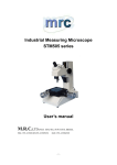
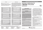
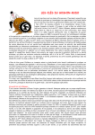
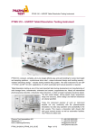
INSTRUCTION MANUAL FOR
TMM.41.X1/X2
Industrial Measuring Microscope
User’s manual
PLEASE READ THIS MANUAL CAREFULLY BEFORE OPERATION
Address: 1805 Jingwei Plaza. No.58 Lane136 Shunde Rd. Haishu Dist.Ningbo China 315012
TEL:86-574-8793-4732 FAX:86-574-8793-4752
Mobile: 86-15305744697 Skype: robertwzj QQ:343779573
www.ningbomicroscope.com
[email protected]
-1-
CONTENTS
PREFACE
1
1. Outline
1
1.1 Description
1
1.2 Specification
1
2. Installation and setup
2
2.1 Package Contents
2
2.2 Installation Site
2
2.3 Setting-up
2
2.4 Checking and Adjustment
3
3. Measurement
6
3.1
Preparation
for
6
Measurement
3.2 Measurement
8
4. Maintenance
9
4.1 Cleaning and Lubrication
9
4.2 Inspection
4.3
Replacing
10
Consumable
11
parts
-2-
PREFACE
Thank you for purchasing the Industrial Microscope. This
User’s Manual explains the hardware operation of the instrument
and the precautions to be observed during operation.To obtain the
best possible performance and longest service life from your
Industrial Microscope,please read this user’s manual thoroughly.
1. Outline
1.1 Description
The Industrial Microscope supports a wide range of
application from shop-floor inspection,measurement of tools and
machined parts,to precision measurement of test tools in a
measuring room.It is designed with angle dial,also can measure
angle.
The Industrial Microscope is easy-to-use and compactly laid
out.It consists of objective、eyepiece、XY stage、angle dial、
reflected illuminator、transmitted illuminator power and so on.
1. Eyepiece
2. Diopter adjustment ring
3. Eyepiece mount
4. Optical tube
5. Reflected illuminator
6. Objective
7. XY stage
8. Angle dial
9. Angle dial clamp screw
10. Vernier
11. Vernier clamp screw
12. Focusing knob
13. Control panel
14. Power panel
-1-
1.2 Specification
(1) Graduation:
Micrometer head:0.0001″(0.00254mm)
Angle dial:1º
Vernier:6′
(2) XY stage feeding range:
Without gauge block:25×25mm(1″ ×1″)
With gauge block:50×50mm(2″ ×2″)
(3)Eyepiece:
Magnification:15X
Field number:13
(4)Objective
Magnification:2X
Working distance:67mm
2 Installation and Setup
2.1 Package Contents
Name
1.objective(2X)
2.Eyepiece(15X)
3.Cross-hair reticule
4.Reflcted illuminator
5.Micrometer Head
6.Reticle setting screw
7.Spare bulb(24v)
8.Spare fuse(0.5A)
9.Power cord
10.Grounding wire
11.User’s Manual
Amount
1
1
1
1
2
1
1
1
1
1
1
2.2 Installation Site
Install the Industrial Microscope in a place which is free form
vibration and dust.
-2-
2.3 Setting-up
1. Install the Micrometer Head on the XY stage.
Loosen the hex-socket head screw on the bracket.If using a
Micrometer Head with a fitting hole in the stem,inset the stem so
the hole is aligned with the clamp screw.If this puts the scale on
the Micrometer Head in a poor position for viewing the zero
graduation,adjust the scale position by turning the Micrometer
Head sleeve.Then,Lighten the hex-socket head screw with the
stem in place.
2. Connect the reflected illuminator cable to the connector on the
power panel,which is at the back of the Industrial Microscope.
3. Set the voltage selector plug to the supply voltage.Turn the fuse
holder to remove the fuse.Pull out the selector plug,insert the
selector plug so that the supply voltage can be seen through the
notch.Insert the fuse into the holder and attach the holder to the
voltage selector plug.
4. Turn off the illuminator select switch knob,and connect the
power cord to the power panel.
2.4 Checking and Adjustment
2.4.1 Checking the reticle position against the XY stage
movement direction
1. Place a small workpiece on the stage glass and bring it into
focus.
2. Turn the Micrometer Heads to align an edge of the workpiece
with the center of the cross-hair.
3. while turning the Micrometer Head to move the workpiece left
and right,turn the angle dial so that the horizontal cross-hair is
oriented to coincide with the direction of the stage movement.
-3-
4. Loosen the vernier clamp screw.Align the 0ºgraduation on the
angle dial with that of the vernier scale.Ensure the margin is
sufficient for adjusting the vernier scale position.
If space for adjusting the vernier scale position is
limited,re-adjust the vernier scale position by referring to
“2.4.3(1)Adjusting the reticle to the XY stage movement
direction.”
2.4.2 Checking the centering of the reticle
To perform dimensional measurement by turning the angle dial or
after replacing the reticle,align the cross-hair with the center of
rotation of the angle dial,as follows.
1. Place a amall workpiece on the stage glass and bring it into
focus.
2. Turn the Micrometer Heads to align an edge of the workpiece
with the center of the cross-hair.
3. Turn the angle dial 180º.Make sure the edge of the workpiece
remains within 3μm of the cross-hair.
If it is not within 3μm,adjust the center of the reticle by referring
to “2.4.3(2) Centering the reticle”.
2.4.3 Adjusting the reticle
(1)Adjusting the reticle with the XY stage moving direction
-4-
1. Remove the clamp knobs from the angle dial and vernier
scale.
2. Remove the four screws from the angle dial cover and
remove the cover.
3. Screw-in the clamp knobs on the angle dial and vernier
scale.
4. Approximately center the vernier scale in the adjustable
range.Then secure it with the clamp knob.
5. Align the 0º graduation of the angle dial with that on the
vernier scale.Then,secure the angle dial with the clamp
knob.
6. Loosen both the adjustment screws and fixing screws(4
pcs.each) so that the eyepiece mount can be moved
manually.
7. While looking into the eyepiece,adjust the position of the
eyepiece mount so that the horizontal cross-hair is oriented
to coincide with the direction of the stage movement.
8. Temporarily secure the eyepiece mount by lightly tightening
the fixing screws.
9. Centering the reticle as described in “(2) Certering the
reticle” below.Firmly secure the eyepiece mount by fully
tightening the fixing screws.
10. Remove the clamp knobs from the angle dial and vernier
-5-
scale.
11. Replace the angle dial cover and secure it to the optical
tube with the four screws.
12. Screw-in the clamp knobs on the angle dial and vernier
scale.
(2) Centering the reticle
1. Place a small workpiece on the stage glass.Turn the
Micrometer Heads to align an edge of the workpiece with the
center of the cross-hair.
2. Rotate the angle scale disc 180º and read the displacement
between the edge of the workpiece and the center of the
cross-hair.
3. Remove the four screws from the angle dial cover and
dismount it Slightiy loosen the four fixing screws.
4. Adjust the eyepiece mount position with the four adjustment
screws to minimize the displacement between the edge of the
workpiece and the center of the cross-hair.Centering is easily
performed by moving the eyepiece mount by half the
displacement in both X and Y directions.Two pairs of
adjustment screws are located at the opposite sides(for
adjusting the X and Y displacements).Adjust the screws in
pairs.Loosen one on one side,and then tighten its counterpart
on the other side to adjust the displacement.
5. Turn the Micrometer Heads to align an edge of the workpiece
with the center of the cross-hair.Rotate the angle dial 180ºand
check the displacement.
6. Repeat steps 1,2,4,5 until the displacement falls within 3.
7. Confirm that the four adjustment screws are fully tightened.
8. Tighten the four fixing screws and replace the angle deal cover.
-6-
3. Measurement
This chapter describes the preparation for measurement and the
measuring procedures.
3.1 Preparations for Measurement
3.1.1 Precautions for measurement
1. Installation site
When selecting an installation site,keep in mind
vibration,dust,and humidity considerations.Vibration can affect
measuring accuracy.Dust and humidity can impair optical
parts,such as the objective and prism,as well as the XY stage
and moving parts.
2. Precaution
If focusing, making measurements, or mounting work pieces,
take the surrounding conditions into account. Be careful not to
bump the objective, stage glassed.
3. Objective and Eyepiece
The supplied objective and eyepiece were finely adjusted
before shipment. To maintain performance and accuracy,
handle them with care and do not disassemble. Do not allow
the surface of the lens to be scratched or to be exposed to
machine oil. If the lens is soiled, clean it as described in
“4.1(3)”.
4. Stage glass
Since workpieces are mounted on it, the stage glass is likely to
be scratched or even severely damaged. Dust the workpiece
before placing it on the stage glass. Exercise care so as not to
bump the stage glass with the workpiece. Do not slide the
workpiece on the stage.
-7-
3.1.2 Illumination modes
The Industrial Microscope supports the following illumination
modes.Select the appropriate illumination mode according to your
application.
(1) Transmitted illumination
The transmitted illumination generates a contour image of the
workpiece,and is suited for measurement and inspection of
workpiece contours.The illuminator is equipped with a green
filter.
(2)Reflected illumination
Reflected illumination shows the surfaces of a workpiece,and is
uesd in observation and inspection of workpiece
surfaces.Adjust the angle and orientation of this illuminator so
the workpiece surface can be observed under optimum
conditions.
The optional twin-bulb reflected illumination unit can be used if
necessary.
(3)Simultaneous use of transmitted and reflected illuminations
Both the contour and surface of the workpiece can be observed
simultaneously.
To switch these illumination modes,use the illuminator select
switch.
3.1.3 Adjusting the diopter
While looking into the eyepiece,turn the diopter adjustment ring
until the reticle can be seen sharply.
3.1.4 Bringing the measuring surface into focus
Bring the measuring surface into focus by moving the optical tube
up and down with the focusing knob.Look into the eyepiece to
make sure the cross-hairs are kept in ocular focus during this
focusing operation.
-8-
If moving the optical tube,be careful,especially if the workpiece is
stepped or is,not to bump the workpiece.
3.1.5 Positioning the workpiece
Align the measuring direction of the workpiece with that of the
stage traverse.
Follow the procedure in “2.4.3(1) Adjusting the reticle with the XY
stage moving direction”.
After making the above adjustment,confirm that alignment is
correct by moving the XY stage as shown below.
3.2 Measurement
3.2.1 Dimensional measurement
Align a measuring point on the workpiece with one of the
cross-hairs and take the reading from the Micrometer
Head.Then,move the XY stage by turning the Micrometer Head
and align another measuring point with the same cross-hair and
take the reading at this point.The difference between the two
readings represents the dimension between the two measuring
points.
3.2.2 Angle measurement
-9-
Angles are measured with the angle dial,using either of the
following two procedures.
(1) Align an edge of the workpiece with cross-hair reticle and align
the end edge with the center of the cross-hair.Turn the angle
dial to align the cross-hair with the other edge of the
workpiece.Take readings from the angle dial.
(2) Align two edges of the workpiece with the same cross-hair,on
after another,by turning the angle dial and moving the XY
stage.Take readings from the angle dial.
1. In both procedures,measuring points on the workpiece are
aligned with a cross-hair,one after another.The angle is
determined from the difference in reading.
2. The resolution of the angle dial is 1ºwith the main scale and
6′with the vernier scale.
3. The zero position of the angle dial can be adjusted by turning
the vernier scale.This allows the angle measurement origin to
be set to 0.After turning the vernier scale,check the reticle
position.Refer to “2.4.3(1) Adjusting the reticle against the XY
stage moving direction” if necessary.
4. Maintenance
This chapter describes the daily and periodical inspection and
maintenance required to maintain the performance of this
microscope.
4.1 Cleaning and Lubrication
- 10 -
(1) Main unit
Periodically apply a thin layer of grease over the slide guide
surfaces and rack of the optical tube using a brush.
(2) XY stage
Apply a thin layer of spindle oil to guide rails.After dusting the
stage glass wipe it gently with a soft cloth.
(3) Eyepiece and objective
Since the optical glass used for lenses is soft and subject to
scratches, always use an air-blower or a feather to dust the
lens surface.To remove contaminants such as oil and
fingerprints,lightly wipe the surface,using soft gauze or
absorbent cotton soaked with high-grade alcohol,in a sircular
motion.
4.2 Inspection
To maintain this microscope in prime condition,periodically inspect
the parts specified below.
(1) Connecting parts
Turn off the illuminator select switch knob and pull out the power
cord from the AC outlet to prevent electric shocks.
Check the power cord,AC inlet,voltage selector,GND
terminal,reflected illuminator connector,and other joints for
looseness and poor connection.
(2) Illuminator select switch and light control knobs
1. Check that the illminator select switch knob is correctly set.
2. Check that the transmitted and reflected illuminators light by
turning the select switch knob to each position.
3. Check that the light intensity of each illuminator changes by
turning the light control knob.
(3) Focusing knob
Check this knob for any abnormal tightness,play,unevenness,and
sound.
- 11 -
(4)XY stage
1. Check the stage glass for scratches and contaminants.
2. Move the XY stage over the measuring range by hand to check
for
any
abnormal
tightness,play,unevenness,and
sound.(Perform the same check on the stage by turning the
micrometer heads.)
(5) Angle dial
Loosen the angle dial clamp knob and turn the dial to check for
any abnormal tightness,play,unevenness,and sound.
(6)Field of view
Look into the eyepiece under transmitted illumination and check
the entire field of view for shading and uneven illumination.
(7)XY stage feeding accuracy
This inspection will be affected by the measuring environment,
alignment error,and other adverse conditions.Keeping these
factors in mind,check the feeding accuracy by measuring a
workpiece of a standard scale with an appropriate dimension of
5mm.
1. Position a workpiece,for which accurate dimension is known,on
the stage glass and bring it into focus.
2. Align a measuring point on the workpiece with one of the
cross-hairs,according to the moving direction of the workpiece.
3. Obtain the dimension from the readings on the Micrometer
Head.Refer to “3.2.1 Dimensional measurement”.
4. Measure the X-and Y-axis dimensions of the workpiece.
If the difference between the measured and nominal dimensions is
less then 5μm (for any 5mm travel range),the XY stage feeding
accuracy is adequate.
(8) Resolution
Position a workpiece on the XY stage and bring it into focus.Check
if any region of the image in the field of view has poor resolution.
4.3 Replacing Consumable Parts
- 12 -
(1) Replacing the fuse
1. Turn the illuminator select switch knob to OFF.
2. Pull out the power cord from the main unit.
3. Turn the fuse holder in the direction indicated by the arrow and
remove it from the voltage selector.Remove the blown fuse the
holder.
4. Insert a new fuse into the holder and replace the holder in the
voltage selector.
(2) Replacing the transmitted illumination bulb
The bulb remains hot after it has been turned off.Do not replace
the bulb until it has become cool.
1. Turn the illuminator select switch knob to OFF.
2. Remove the stage glass.
3. Turn the green filter counterclockwise to remove it.
4. Remove the bulb by turning it with the supplied bulb setter.
5. Mount a new bulb using the bulb setter.
6. Switch the illuminator select switch knob to transmitted
illumination.Check that the bulb lights.
7. Replace the green filter and the stage glass,in this order.
(3) Replacing the reflected illumination bulb
The bulb remains hot after it has been turned off.Do not replace
the bulb until it has become cool.
1. Turn the illuminator select switch knob to OFF.
2. Turn the white filter counterclockwise to remove it.
3. Remove the bulb by turning it with the supplied bulb
setter.Mount a new bulb using the bulb setter.
4. Switch the illuminator select switch knob to the reflected
illumination.Check that the bulb lights.
5. Replace the white filter.
- 13 -
Packing List
Name
Quantity
1. Industrial microscope
1
2. Hex-socket head spanner
1
3. Watch screwdriver 2 #
1
4. Gauge block 25mm
2
5. Small lamp
2
6. Fuse
24V 0.11A
250V 0.5A
1
7. Special tool for installation lamp
1
8. Working table glass
1
9. User’s manual
1
- 14 -