1
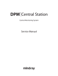
HYPERVISOR VI
Central Monitoring System
Service Manual
Intellectual Property Statement
SHENZHEN MINDRAY BIO-MEDICAL ELECTRONICS CO., LTD. (hereinafter
called Mindray) owns the intellectual property rights to this product and this manual.
This manual may refer to information protected by copyrights or patents and does not
convey any license under the patent rights of Mindray, nor the rights of others.
Mindray does not assume any liability arising out of any infringements of patents or
other rights of third parties.
Mindray intends to maintain the contents of this manual as confidential information.
Disclosure of the information in this manual in any manner whatsoever without the
written permission of Mindray is strictly forbidden. Release, amendment,
reproduction, distribution, rent, adaptation and translation of this manual in any
manner whatsoever without the written permission of Mindray is strictly forbidden.
and
are the registered trademarks or trademarks owned by
Mindray in China and other countries. All other trademarks that appear in this manual
are used only for editorial purposes without the intention of improperly using them.
They are the property of their respective owners.
Contents of this manual are subject to changes without prior notice.
For this manual, the issued Date is January 2006 (Version: 1.0).
© 2005 Shenzhen Mindray Bio-Medical Electronics Co., Ltd. All rights reserved
I
Manufacturer’s Responsibility
All information contained in this manual is believed to be correct. Mindray shall not
be liable for errors contained herein nor for incidental or consequential damages in
connection with the furnishing, performance, or use of this manual.
Mindray is responsible for safety, reliability and performance of this product only in
the condition that:
All installation operations, expansions, changes, modifications and repairs of this
product are conducted by Mindray authorized personnel; and
The electrical installation of the relevant room complies with the applicable
national and local requirements; and
This product is operated under strict observance of this manual.
Warranty
This warranty is exclusive and is in lieu of all other warranties, expressed or implied,
including warranties of merchantability or fitness for any particular purpose.
Exemptions
Mindray's obligation or liability under this warranty does not include any
transportation or other charges or liability for direct, indirect or consequential
damages or delay resulting from the improper use or application of the product or the
use of parts or accessories not approved by Mindray or repairs by people other than
Mindray authorized personnel.
This warranty shall not extend to
Any Mindray product which has been subjected to misuse, negligence or
accident; or
Any Mindray product from which Mindray's original serial number tag or
product identification markings have been altered or removed; or
Any product of any other manufacturer.
II
Return Policy
In the event that it becomes necessary to return a unit to Mindray, follow the
instructions below.
1.
Obtain a return authorization.
Contact the Mindray Service Department and obtain a Mindray Customer Service
Authorization Number. The Mindray Customer Service Authorization Number must
appear on the outside of the shipping container. Return shipments will not be accepted
if the Mindray Customer Service Authorization Number is not clearly visible. Please
provide the model number, serial number, and a brief description of the reason for
return.
2.
Freight policy
The customer is responsible for freight charges when this product is shipped to
Mindray for service (including any relevant customs fees or other freight related
charges).
3.
Return address
Please send the part(s) or equipment to the address offered by Customer Service
Department.
III
Contact Information
Manufacturer:
Shenzhen Mindray Bio-Medical Electronics Co., Ltd.
Address:
Mindray Building, Keji 12th Road South, Hi-tech Industrial
Park, Nanshan, Shenzhen 518057 P.R. China
Tel:
+86 755 26522479
+86 755 26582888
Fax:
+86 755 26582500
+86 755 26582501
Website:
www.mindray.com.cn
EC-Representative:
Shanghai International Holding Corp. GmbH (Europe)
Address:
Eiffestraße 80, 20537 Hamburg Germany
Tel:
0049-40-2513175
Fax:
0049-40-255726
IV
Safety Precautions
1.
Meaning of Signal Words
In this service manual, the signal words
DANGER,
WARNING,
CAUTION and NOTE are used regarding safety and other important instructions.
The signal words and their meanings are defined as follows. Please understand their
meanings clearly before reading this manual.
DANGER
Indicates an imminent hazard situation that, if not avoided, will result in
death or serious injury.
WARNING
Indicates a potential hazard situation or unsafe practice that, if not
avoided, could result in death or serious injury.
CAUTION
Indicates a potential hazard or unsafe practice that, if not avoided, could
result in minor personal injury or product/property damage.
NOTE
Provides application tips or other useful information to ensure that you
get the most from your product.
V
2.
Symbol
Meaning of Safety Symbols
Description
Type-BF applied part
"Attention"
3.
(Refer to the operation manual.)
Safety Precautions
Please observe the following precautions to ensure patient and operator safety when
using this system.
CAUTION
Malfunctions due to radio waves
Use of radio-wave-emitting devices in the proximity of this kind of
medical electronic system may interfere with its operation. Do not
bring or use devices which generate radio waves, such as cellular
telephones, transceivers, and radio controlled toys, in the room where
the system is installed.
If a user brings a device which generates radio waves near the system,
they must be instructed to immediately turn OFF the device. This is
necessary to ensure the proper operation of the system.
Do not allow fluids such as water to contact the system or peripheral
devices. Electric shock may result.
DANGER
Do not use flammable gasses such as anesthetics, or flammable liquids
such as ethanol, near this product, because there is danger of
explosion.
WARNING
Do not connect this system to outlets with the same circuit breakers
and fuses that control current to devices such as life-support systems.
If this system malfunctions and generates an overcurrent, or when there
is an instantaneous current at power ON, the circuit breakers and fuses
of the building’s supply circuit may be tripped.
VI
Contents
Intellectual Property Statement ············································································· I
Manufacturer’s Responsibility··············································································II
Warranty................................................................................................................... II
Exemptions............................................................................................................... II
Return Policy ········································································································ III
Contact Information ···························································································· IV
Safety Precautions··································································································V
Contents ···················································································································1
1
1.1
1.2
2
Introduction ········································································································· 1-1
Overview............................................................................................................... 1-1
System Components.............................................................................................. 1-3
Installation ··········································································································· 2-1
2.1
2.2
2.3
2.4
About the installation of the Central Monitoring System ..................................... 2-1
Requirements on Environment.............................................................................. 2-2
Installation of Windows XP Professional.............................................................. 2-3
Installation of the Drivers...................................................................................... 2-4
2.4.1
Driver of the display card.............................................................................. 2-4
2.4.2
Driver of network card .................................................................................. 2-5
2.4.3
Driver of sound card...................................................................................... 2-8
2.4.4
Installation of printer..................................................................................... 2-8
2.4.5
Installation of recorder .................................................................................. 2-8
2.4.6
Installation of USB watchdog driver............................................................. 2-9
2.4.7
Shutoff of Windows XP Fire Wall................................................................. 2-9
2.5
Adjusting the System .......................................................................................... 2-10
2.5.1
Setting the time delay of the system startup and recovery .......................... 2-10
2.5.2
Overrwriting Mode of Log Files ................................................................. 2-10
1
Contents
2.5.3
Disabling sound............................................................................................2-11
2.5.4
Setting Power Management Property.......................................................... 2-12
2.6
Installation of MSDE .......................................................................................... 2-14
2.7
Installation of the Central Monitoring System .................................................... 2-15
3
Quick Recovery ··································································································· 3-1
3.1
Overview............................................................................................................... 3-1
3.1.1
Application Scope ......................................................................................... 3-1
3.1.2
Precautions .................................................................................................... 3-1
3.2
Installation Procedure............................................................................................ 3-2
3.2.1
Making the Recovery Start Floppy Disk ....................................................... 3-2
3.2.2
Quick Recovery Procedure............................................................................ 3-3
4
Maintenance and Cleaning················································································· 4-1
4.1
Maintenance .......................................................................................................... 4-1
4.1.1
General Inspection ........................................................................................ 4-1
4.1.2
System Performance Test .............................................................................. 4-1
4.2
Cleaning ................................................................................................................ 4-3
5
Troubleshooting··································································································· 5-1
5.1
5.2
5.3
5.4
5.5
5.6
Recorder/printer-related technical alarm messages............................................... 5-1
The CMS fails to display information of a monitor .............................................. 5-1
No waveform displayed in waveform review ....................................................... 5-1
“Display Mode Error” appears on the dual-screen CMS ...................................... 5-1
Dual-screen changes to Single-screen during the CMS installation...................... 5-1
Slow wave speed or database error message occurs during waveform reviewing 5-4
2
1
Introduction
1.1
Overview
HYPERVISOR VI Central Monitoring System (CMS) is intended for professional
physicians or paramedics to conduct centralized monitoring over multiple patients
monitored by individual monitors in hospitals or medical institutions.
The central monitoring system comprises powerful system software and
high-performance computer. It constructs a monitoring network by connecting
monitors. By collecting, processing, analyzing and outputting the information coming
from monitors, the central monitoring system can achieve centralized monitoring over
multiple patients so as to greatly promote the efficiency and quality of the monitoring
work.
The central monitoring system:
Is capable of connecting up to 64 monitors that supports the CMS or CMS+
network protocol.
Is capable of connecting up to 16 telemetry transmitters and supporting 1-16
transmitter frequency configurations.
Supports multi-screen display mode, including two primary displays and
multiple secondary displays.
Is capable of displaying information from 16 monitors in the single-screen mode
and 32 monitors in the dual-screen mode.
Allows you to view a single patient emphatically.
Allows you to review up to 240 hours of trend data for each online patient.
Allows you to review up to 720 alarm events for each online patient.
Allows you to save and review a 4-hour dynamic short trend for each online
patient.
Allows you to review up to 720 CO measurements for each online patient.
Allows you to review up to 72 hours of 64 waveforms.
Allows you to review up to 720 NIBP measurements for each online patient.
Allows you to search for, review and maintain the data of up to 20,000 history
patients.
Provides the patient information management function.
1-1
Introduction
Provides four alarm indications: audible alarm, visual alarm, alarm icon and
alarm message.
Provides the functions of drug calculation, titration table calculation and
hemodynamics calculation.
Provides the functions to record, print and save data.
Provides comprehensive help information, prompts and operational guide.
Supports 1280×1024 high display resolution.
Facilitates the setup of language, waveform and parameter color.
Supports such peripherals as the keyboard, mouse, thermal recorder, laser printer,
speaker, etc.
Supports wire and wireless network.
The central monitoring system has a USB watchdog to protect the copyright. You
must plug the watchdog into the system’s USB interface before starting the system.
Otherwise, the system cannot start.
1-2
Introduction
1.2
System Components
Hardware components of the central monitoring system should be highly reliable and
stable. The hardware components of your system should meet the following
requirements at least.
Components
System
Requirements
Meet the IEC60950 requirements defined for ITE equipment, and
Comply with CE low voltage directives (LVD) and EMC directives.
PC compatible, with CE marking
CPU: PIV 2.0GHz
256M RAM
Host
40G Fixed Diskette
Network card: 10M/100M Base-T, Ethernet 802.3, RJ45 interface
3 USB interfaces
1 serial port
1 parallel port;
Display
1280×1024 17"TFT, with CE marking.
Mouse
PS/2 or other standard interface, with CE marking
Keyboard
PS/2 or other standard interface, with CE marking.
Recorder
Thermal array, serial port
Printer
HP LaserJet series, supporting A4 paper
Speaker
Internal speakers (of the computer or the display).
NOTE
The configuration above is for reference only.
1-3
2
Installation
2.1
About the installation of the Central
Monitoring System
This installation guide is to introduce how to configure the machine from the very
beginning to the state that the Central Monitoring System can be normally operated.
The installation includes the following:
CMOS configuration, partition and installation of Windows XP Professional
Installation of display card, sound card, and network card drivers
Installation of printer and recorder
Installation of USB watchdog driver
Fire Wall shutoff
System adjustment
Installation of MSDE
Installation of the Central Monitoring System
NOTE
Although Windows is public software, due to the particularity of this
system, it cannot be set up at one’s disposal, even if the people is an
expert for installation of Windows system. The relevant installation and
setup must be performed in terms of this installation guide, to ensure
the correct operation of the system.
The following CDs are needed for the complete installation of the Central
Monitoring System:
Installation CD of Microsoft Windows XP Professional
Driver CD components
System software installation CD of the central monitoring system
2-1
Installation
2.2
Requirements on Environment
1.
Hardware environment
CPU: above PIV 2.0 GHz.
Internal memory: above 256 M.
Hard disk: above 40G.
Display card, network card, sound card, COM port, USB port, printer, sound
box.
Display: 17", 65535 color, display setting of 1280×1024.
NOTE
The selection of the display card depends on the mode of the central
monitoring system. For the dual-screen function, select the dual-screen
display card, and the two displays shall be of same type. The two
displays are respectively connected to the “1” port and “2” ports of the
dual-screen display card.
2.
Software environment
Operating system: Microsoft Windows XP Professional
Database: MSDE
2-2
Installation
2.3
Installation of Windows XP Professional
Prior to the installation of Windows XP Professional, CMOS shall be set up:
1.
Set the administrator’s password to “Hypernet” (pay attention to lower and upper
case).
2.
Set the system to boot from CD. However, after the system installation is
completed, set the system to boot from the hard disk.
Select a specific language version of the operating system according to the user’s
requirement, and then use the installation CD of Windows XP Professional to initiate
the installation. The procedures of the installation are shown as follows:
1.
Create C partition, whose size is 10G, and the file system is NTFS. Partition the
remaining space into D and E, and the space of E is 5G, and the file system is
FAT32. The space left is D partition, and the file system is NTFS.
2.
In the installation program of Windows, enter the names of the user and
company: “Hypervisor” and “Company".
3.
In the installation program of Windows, enter the name of the computer and
Administrative Password: “HYPERVISORVI” and “Hypernet” (pay attention to
lower and upper case).
4.
In the components of Windows installation program, select the default
installation.
5.
After the system is installed, activate the operating system of Windows XP,
either by means of telephone or network. Enter the screen of activation, and then
select the mode of activation, and perform the operations according to the
prompts.
2-3
Installation
2.4
Installation of the Drivers
The installation of the drivers depends on the hardware.
2.4.1
Driver of the display card
The installation of the display card driver depends on the modes of the central
monitoring system. If it is single-screen, select the installation program of
single-screen mode. If it is dual-screen, select the installation program of dual-screen
mode.
In the single-screen mode, install the driver and restart the system, and then set the
display properties. Right click the mouse in the Windows background, choose”
Properties”, go to “Display Properties”, Set the color in the single-screen mode to
real color(32 bits), and set the screen area to 1280×1024 in “Setting”; in the
advanced options, set DPI to normal size in “General”; set the refresh frequency to
75Hz in “Monitor”.
For the dual-screen mode, install the dual-screen display card, and then connect the
display, and respectively connect the primary display and secondary display to the “1”
port and “2” port of the dual-screen display card. After the driver is installed, restart
the system, and set up the display properties. Right click mouse in the Windows
backgrount,, then choose “Propertie”, go to “Display Properties”, Set the color to real
color (32 bits), and set the screen area to 1280×1024; in the advanced options, set DPI
to normal size; set the refresh frequency to 75Hz, and set the display to horizontal
span.
2-4
Installation
Note:The setting of display card is just for reference, there may be some difference
according to different display card, for more information, please reference the your
display card reference manual.
2.4.2
Driver of network card
Set the TCP\IP protocol after installation of the corresponding network card driver.
1.
“Start” ”All Programs” ”Accessories” ”windows Explorer” go to windows
explorer, right click the mouse, choose “Properties” in “My Network Places”,
you can see:
2-5
Installation
2.
Choose “Local Area Connection”, then right click the mouse, and choose
“Properties”,you can see the following interface:
3.
Choose “Internet Protocol (TCP/IP)”, click “Properties”, then you can see:
4.
Set as the picture, click “Advanced…”, you can see:
2-6
Installation
5.
Click “Add…” bellow “IP addresses”, then you can see:
NOTE:
6.
Submask code for 196.76.0.1 must be255.255.0.0
Click “Add”, return to the following interface:
2-7
Installation
7.
2.4.3
Click “OK”
to finish.
Driver of sound card
It only needs to install the driver, with no other setups required.
2.4.4
Installation of printer
After the driver of the printer is installed, set the name of the printer to HyperPrinter.
The sharing mode is “No share”.
2.4.5
Installation of recorder
Since there isn’t software driver for the recorder, the recorder will be directly driven
by the central monitoring system.
2-8
Installation
2.4.6
Installation of USB watchdog driver
The USB watchdog driver is located at the USB directory in CD components of
“the system software of the central monitoring system”. After the driver of USB
watchdog is installed, insert the USB watchdog into the USB interface of the
machine.
2.4.7
Shutoff of Windows XP Fire Wall
1.
“Start” ”Control Panel” go to “Control pannel”. Choose “Security Center”, you
can see:
2.
Choose “Windows Firewall” , you can see:
3.
Set as the picture, click “OK” to finish.
2-9
Installation
2.5
Adjusting the System
After the installation is completed, it is necessary to adjust some setups to ensure the
normal operation of the system.
2.5.1
Setting the time delay of the system startup and
recovery
2.5.2
1.
“Start” ”Control Panel”
2.
Go to ”Performance and Maintenance” then choose “System”, open” Advanced”,
you can see:
3.
Click setting “Startup and Recovery”, you can see:
4.
Set as the picture, click “OK”.
Overrwriting Mode of Log Files
1.
Go to “Start” ”Control Panel”.
2-10
Installation
2.5.3
2.
Choose “Performance and Maintenance” , the choose “Administrative Tools”,
open “Event Viewer”,you can see :
3.
Choose”Application” “Security””System”seperately, right click mouse, choose
“Properties”, you can see:
4.
Set “System” ”Security” “Application” log siz to
needed” seperately..
“Overwrite events as
Disabling sound
1.
Go to “Start” ”Control Panel”
2.
Choose “Sounds,Speech,and Audio Devices”,choose “Sounds and Audio
Devices”, open “Sounds”, you can see::
2-11
Installation
3.
Set as the picture, then there will be a pop up window:
4.
Click “No”, then click “Ok”.
Note:After finish setting, there should not a shape of amall speaker befor any of the
item.
2.5.4
Setting Power Management Property
1.
Select “Start” ”Control Panel” go to “control pannel”
2.
Choose “Performance and Maintenance”, then choose “Power Options”, you can
see:
2-12
Installation
3.
You can set as the up picture., then click “OK”.
2-13
Installation
2.6
Installation of MSDE
After the operating system of Windows XP Professional is installed, and restarted,
installation of MSDE can be started if the system is normal. The central monitoring
system needs the support of database, so the system is applied with the MSDE
database system. MSDE is located at the MSDE directory of CD components of “the
system software of the central monitoring system”. Enter “Start” “Run”
“X:\MSDE\setup.exe SecurityMode=SQL”, As show in the picture(in the “Run”
dialog box, enter CD to select setup.exe by the Browse button, input the
SecurityMode=SQL manually). X represents the installation CD symbol of MSDE
2000. Click “OK” to start the installation, and restart the system after the installation
is completed.
NOTE
You can not click setup.exe to insall.
In the “Run” column, do not forget to input “SecurityMode=SQL”.
2-14
Installation
2.7
Installation of the Central Monitoring System
For the system software installation of the central monitoring system , first copy all
files under the setup directory of “the system software of the central monitoring
system” CD to the D partition, and then run the configuration program “HyperVI
Config Tool.exe”, and select the language and the name of the OEM company.
Finally a new “setup” folder is generated in this folder, and then run the installation
program in this newly generated folder. During installation, it only needs to select the
default language of the central monitoring system, and input the names of hospital
and office, and then the database is generated. For other options, install as defaulted.
After the installation is completed, delete the copied “setup” folder and all files under
it.
NOTE
If you select the generation of the database, the data in the database will
be deleted. If you only want to resume the software of the central
monitoring system, it is not necessary to select the generation of the
database, thus the previous data can be remained. But if it is your first
time to install the software of the central monitoring system, you must
select the generation of the database.
For the background wallpaper of single- or dual-screen, enter the
installation directory of the central monitoring system and select
“1280X1024” or “2560X1024” (depending on the single-screen or
dual-screen mode), and select “Layout” for the wall paper display. Set
the screen saver to “None”.
2-15
3
Quick Recovery
3.1
Overview
This guide is intended for quick recovery installation of the central monitoring system,
so as to restore the system to its initial factory configuration.
3.1.1
Application Scope
It is a must to confirm the cause of system failure before using this tool. If the system
failure relates to hardware, this tool will be inapplicable. For example, the computer
cannot be started due to hard disk fault. In this case, you must replace the hard disk
before re-installing the operating system and the CMS software.
If the system failure relates to software (including the operating system and CMS
software) and the partition of the hard disk still meets the factory requirements, this
tool will be applicable.
3.1.2
Precautions
All files used for quick recovery installation are saved under Disk E; therefore, any
operation on the E partition by the user is forbidden:
Deleting a file
Adding a file
Modifying a file name
Formatting
Changing a drive symbol
Format of partition. The E partition must be in the FAT32 format whereas the C and D
partitions must be in the NTFS format.
Changing the hard disk partition information, including drive symbol for each
partition, format and size of partition.
In case the recovery fails due to incomplete files on Drive E or changed partition
information,,you must re-install the operating system and the central monitoring
system.
In addition, the user must backup the “MAKEBOOT.exe” file under the Disk E (used
for making the recovery boot disk) on other storage media (like PC, mobile hard disk,
CD) and ensure that a recovery boot disk (see 2.1 for the making procedure) is
available at any time. By doing so, the recovery start floppy disk can still be made
when the Windows operating system is inaccessible.
3-1
Quick Recovery
NOTE
Quick recovery will format the C and D partitions of the hard disk;
therefore, backup your desired data in the C and D partitions before
performing the recovery operation. Our company assumes no
responsibility for loss of data during the recovery process.
3.2
3.2.1
Installation Procedure
Making the Recovery Start Floppy Disk
This recovery start floppy disk is used to start the computer, thus starting the quick
recovery procedure.
1.Make sure the floppy drive and floppy disk (1.4M) are available.
Enter the Windows system and insert the 1.4M floppy disk; then, double-click the
“E:\MAKEBOOT.exe” file as shown below.
2.Click “YES” in the message box as shown in Figure 2.
3.The following message box will be displayed as shown in Figure 3. Click “YES”.
3-2
Quick Recovery
4.The system writes the floppy disk. At the end, the screen automatically disappears.
See Figure 4
3.2.2
Quick Recovery Procedure
Preparation
Verify the start order of the main board CMOS. The first one must be the floppy drive
Make sure the recovery start floppy disk is already made.
1.
Insert the recovery start floppy disk and restart the computer; then, wait to enter
the recovery option menu.
2.
Enter the recovery option menu as shown in Figure 5.
Input “a” or “b”(in either lower case or upper case).
Select “A” to recover the C partition only, i.e., only the operating system and
Hypervisor VI central monitoring system are recovered.
Select “B” to recover both C and D partitions, i.e., the operating system, Hypervisor
3-3
Quick Recovery
VI central monitoring system and database are all recovered.
NOTE
If the D partition is recovered, all data in the CMS database will be lost
and the database will restore the initial factory configuration.
3.
After “a” or “b” is input, the following message will be displayed:
You can either input “y”(in either lower case or upper case)to confirm the recovery
operation, or input “n” to return to the previous step.
4.
During the whole recovery process, human interference is undesired. The system
will display the recovery screen “Ghost 8.2” indicating the recovery progress.
Note that the recovery screen “Ghost 8.2” will be started twice if you select to
recover both C and D partitions.
After the recovery is finished, the system will automatically restart. At this time, the
recovery start floppy disk must be taken out.
3-4
4
Maintenance and Cleaning
4.1
Maintenance
Failure on the part of the responsible hospital or institution employing the use of the
central monitoring system to implement a satisfactory maintenance schedule may
cause undue equipment failure and possible health hazard.
4.1.1
General Inspection
Before the central monitoring system is put into use and when it is in use, follow these
guidelines to inspect it:
Inspect the equipment and its accessories for mechanical damage;
Inspect if the environment and power supply meet the specified requirements;
Inspect all power cords and signal lines for fraying or other damages, and if they are
properly connected and insulated;
Inspect if the sound system functions normally;
Inspect if each function of the system is in good condition;
In case of any damage or abnormity, do not use the central monitoring system.
Contact the hospital biomedical engineers or our service personnel immediately.
4.1.2
System Performance Test
When the central monitoring system has software failure or after quick recovery
installation is performed, follow this procedure to make sure that the system functions
correctly:
Whole system performance test
Connection and self-test
Communication test
Main menu function
Basic monitoring function
Freeze currently displayed waveforms
Real-time recording
Recorder control
Single patient monitoring function
4-1
Maintenance and Cleaning
Patient management
ViewBed
Show/hide high/low parameter limits
Show/hide dynamic short trend
Set module order
Show/hide multi-lead ECG
Show/hide OxyCRG
Show/hide NIBP groups
Alarm setup
Drug calculation
CO review
Hemodynamics calculation
Waveform review
Trend review
Alarm review
Display setup
Functional test of auto arrange
Functional test of admitting patient
Functional test of system setup
General setup
System software version
Print control
Record control
Functional test of history review
System help
Record and print
Bi-directional control
Functional test of Watchdog
4-2
Maintenance and Cleaning
Clear database
“Resolution notification” function disabled
Shut down
4.2
Cleaning
Your equipment should be cleaned on a regular basis. If there is heavy pollution in
your place or your place is very dusty and sandy, the equipment should be cleaned
more frequently. The equipment to be cleaned includes the host, displays, printer,
recorder, keyboard and mouse.
The exterior surfaces of the equipment may be cleaned with a clean and soft cloth,
sponge or cotton ball, dampened with a non-erosive cleaning solution. Drying off
excess cleaning solution before cleaning the equipment is recommended. Following
are examples of cleaning solutions:
Diluted soap water
Diluted ammonia water
Hydrogen peroxide (3%)
Isopropyl alcohol
Follow these rules to clean the equipment; otherwise, it may melt, distort, or dull the
finish of the case, blur lettering on the labels, or cause equipment failures.
ALWAYS dilute the solutions according to the manufacturer’s suggestions.
ALWAYS wipe off all the cleaning solution with a dry cloth after cleaning.
NEVER SUBMERGE the equipment into water or any cleaning solution, or POUR or
SPRAY water or any cleaning solution on the equipment.
NEVER permit fluids to run into the casing, switches, connectors, or any ventilation
openings in the equipment.
NEVER use abrasive materials and erosive or acetone –based cleaners.
4-3
5
Troubleshooting
5.1
Recorder/printer-related technical alarm
messages
See the instructions for use of HYPERVISOR VI Central Monitoring System, 2.2.
5.2
The CMS fails to display information of a
monitor
Make sure that the monitor’s local net number is not set repeatedly. Otherwise, the
monitor cannot be connected to the CMS normally.
Check if the network is properly connected. If the network is not properly connected
or the network cable is broken, the monitor’s information cannot be transmitted to the
CMS.
5.3
No waveform displayed in waveform review
This symptom indicates that the user does not add the waveforms that need to be
saved. To remove this fault, click in the patient window and then select “Display
Setup” to enter the “Display Setup” tab sheet, select “Wave Save” and then add your
desired waveforms.
5.4
“Display Mode Error” appears on the
dual-screen CMS
This symptom indicates that the video adapter is set incorrectly. To remove this fault,
UNPLUG the USB watchdog and restart the system; when “Please Insert USB
Watchdog” appears on the screen, click
“Property”→“Setup”→“Advance”→“Dualhead”→ “Fealure” (double click) or
“+”→“Dualhead multi-display”→“Ok” after changing the settings→“Apply” after
setting the screen size as 2560X1024→“Ok”.
5.5
Dual-screen changes to Single-screen during
the CMS installation
Note:The following setting of display card is just for reference, there may be some
5-1
Troubleshooting
difference according to different display card, for more information, please reference
the your display card reference manual.
Plug the watchdog and restart the computer. Then, click “Start”→“Setup”→“Control
Panel”→“Display”→“Advanced”;
Here should be 2048*768
Here to change resolution
5-2
Troubleshooting
In the “Plug and Play Monitor” window, select “Screen Resolution&Refresh Rats”
and then click “Add“, input 2560 and 1024 manually.
Set the resulation to 2560X1024
Change it to 2560*1024
4.
Set display mode to Horizontal Span.
5-3
Troubleshooting
Choose Horizontal
5.6
Slow wave speed or database error message
occurs during waveform reviewing
Such symptoms may occur due to too many saved data. To remove these faults, delete
part of patient history data, or recover the system according to the instructions in 2.2.
5-4
P/N:300B-20-47613(1.0)