1
Portable Test Transmitter
Technical Manual
U110103
Glenn Toennes
September 2006
Lumistar, Inc.
5870 El Camino Realt
Carlsbad, California 92008 USA
Lumistar Portable Test Transmitter
Table of Contents
Table of Contents
1 — Introduction
1.1 General............................................................................................................... 1-1
1.2 Specifications..................................................................................................... 1-1
Table 1–1. General Specifications ............................................................. 1-1
Table 1–2. PCM Transmitter Specifications .............................................. 1-1
Table 1–2. PCM Simulator Specifications ................................................. 1-2
2 — Installation
2.1 Physical .............................................................................................................. 2-1
2.2 Power ................................................................................................................. 2-1
2.3 Connections ....................................................................................................... 2-1
2.3 Software ............................................................................................................. 2-2
3 — Operation
3.1 General............................................................................................................... 3-1
3.2 Front Panel Controls ........................................................................................ 3-1
3.2.1 Keypad..................................................................................................... 3-2
3.2.2 RF Parameter Settings ........................................................................... 3-2
3.2.3 PCM/PRN and INT/EXT....................................................................... 3-2
3.2.4 RF Output Control ................................................................................. 3-3
3.3 Baud Rate Recovery ......................................................................................... 3-3
3.4 LS11HandHeld.exe ........................................................................................... 3-3
3.4.1 Menu Bar................................................................................................. 3-3
3.4.1.1. File Menu ..................................................................................... 3-3
3.4.1.2. Config Menu ................................................................................ 3-4
3.4.1.3 LoadAll .......................................................................................... 3-4
3.4.2 Format Name Bar................................................................................... 3-4
3.4.3 Handheld Screens ................................................................................... 3-4
3.4.4 Simulator Page........................................................................................ 3-5
3.4.5 Transmitter Tab ..................................................................................... 3-5
3.4.6 Query Tab ............................................................................................... 3-5
4 — Programming Information
4.1 Serial Communications .................................................................................... 4-1
4.1.1 Select Format Number ........................................................................... 4-2
4.1.2 Set Format Name.................................................................................... 4-2
4.1.3 Recall ....................................................................................................... 4-2
4.1.4 Simulator Run/Halt ................................................................................ 4-2
4.1.5 RF Parameters ........................................................................................ 4-3
4.1.6 Clock Generator ..................................................................................... 4-4
4.1.7 Mode Registers........................................................................................ 4-4
September 2006
ii
Lumistar
Lumistar Portable Test Transmitter
Table of Contents
4.1.8 Memory Access ....................................................................................... 4-5
Table 4–1. Frame Start Register (0 T)........................................................ 4-5
Table 4–2. Mode Register (1 T) ................................................................. 4-6
Table 4–3. Code Register (2 T) .................................................................. 4-6
Table 4–4. Simulator Memory Map ........................................................... 4-8
4.1.9 Save Format ............................................................................................ 4-8
Table 4–5. Simulator Word Attributes ....................................................... 4-8
Table 4–6. Simulator Frame Attributes...................................................... 4-8
4.1.10 Return Status ........................................................................................ 4-9
4.1.11 Configuration EEPROM ..................................................................... 4-9
4.1.11.1 Options ...................................................................................... 4-10
Table 4–7. EEPROM[14] Options ........................................................... 4-10
4.1.12 Direct D/A Write................................................................................. 4-10
5 — LS11Q
5.1 General............................................................................................................... 5-1
Table 5–1. LS11Q Specifications............................................................... 5-1
5.2 LS11Q Front Panel I/O .................................................................................... 5-1
5.3 LS11Q Operation.............................................................................................. 5-2
5.4 LS11Q Programming Information ................................................................. 5-2
5.4.1 LS11QRF Parameters ............................................................................ 5-2
5.4.2 LS11Q Status Query............................................................................... 5-3
September 2006
iii
Lumistar
Lumistar Portable Test Transmitter
Introduction
1 — Introduction
1.1 General
The Lumistar Portable Test Transmitter (herein, "Handheld," albeit it is
admittedly quite a handful – it takes a chunk of lead to hold 75 watt-hours)
provides a convenient sample signal for field link checkout. A flexible
preprogrammed PCM simulator can modulate a low-powered wideband
FM transmitter. The simulator is packaged in a convenient carrying box.
The test transmitter offer's a full shift's battery operation and includes an
on-board battery charger/eliminator.
The “LS11Q,” as referred to herein, uses a Quasonix QSX-VST RF
transmitter module to provide an SOQPSK output capability. This model
has a number of differences summarized in Chapter 5.
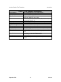
1.2 Specifications
Table 1–1. General Specifications
Form Factor
Power Dissipation
Battery Capacity
Temperature (Operating)
Temperature (Non-Operating)
Host Interface
9" long x 6" wide x 7-1/2" deep with cover.
Less than 10 watts.
Greater than 12 hours when fully charged.
0 to 50 oC
-25 to +70 oC
RS-232 19200 baud, 8-bit, 1 stop, ASCII without parity.
Optional: 600, 1200, 2400, 4800, 9600, 38400, 115200 baud.
Table 1–2. PCM Transmitter Specifications
RF Band
Tuning Range
Modulation Type
Modulation Source
Output Power
Pre-Modulation Filter
FM Deviation
September 2006
LS11: S-Band (2200-2400MHz.)
200MHz max
Wideband FM
PCM Simulator or Front-Panel Baseband input
-60 to +10dBm Max (approximate) in 5dB steps
Four selectable 4-Pole Bessel Filters, F1 points 0.5MHz,
1MHz, 2.5MHz, 5MHz. Others on special order.
150kHz .. 7000kHz Peak in 10kHz increments
1-1
Lumistar
Lumistar Portable Test Transmitter
Introduction
Table 1–2. PCM Simulator Specifications
Format Selection
Front Panel Outputs
Output Levels
Output Data Rate
PCM Codes
Word Length
CRC Generator
Minor Frame Length
Major Frame Length
Bit Order
Frame Sync Pattern
Major Frame Sync
Common Words
Unique Words
Test Output
Waveform Words
September 2006
Four format definitions in non-volatile memory
NRZ-L and PCM Data, 0-degree clock & minor frame strobe
Single-ended TTL
100bps to 20Mbps (NRZ codes)
100bps to 10Mbps (all other codes)
NRZ-L/M/S; Bi-Phase -L/M/S; DM-M/S; M2, RNRZ-L11/15, k=7
Convolutional Rate 1/2, 1/3
Variable from 3 to 16 bits per word on a word-by-word basis
CRC16/CCITT Forward/Reverse
2 to 8,192 words per minor frame
Up to 1024 minor frames per major frame
MSB or LSB-first
Up to 256 words (any series of 0s or is 1s may be used)
FCC (FAC), SFID
May be a single value or selected from a group of one minor
frame.
Seven may be programmed in any mainframe, supercommutated, or sub-commutated channel.
32,767-bit PRN pattern
Five may be programmed to appear in every frame at the same
location.
1-2
Lumistar
Lumistar Portable Test Transmitter
Installation
2 — Installation
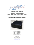
2.1 Physical
The LS11 is housed in a 9”x6”x7.5” ZERO case.
2.2 Power
Set the 115/230 switch on the front panel according to which continent
you're on. Prime power input is a standard male IEC connector on the
panel. We provide a power cord for US use.
The unit includes a battery charger that is powered whenever the
unit is plugged in, regardless of the state of the power switch.
2.3 Connections
All I/O connections are through the front panel.
The host interface is a female DE09 connector pin-compatible with 9-pin
Personal Computer serial interfaces.
The RF output is a type "N" connector.
Five BNC connectors are provided.
The external input can be selected as a modulation source. This input is
terminated into 75 ohms and the expected input signal is 2V p-p for
indicated deviation.
Four Test outputs are provided.
The Baseband output is a bipolar PCM output with a nominal signal level
of 2V p-p terminated into 75 ohms.
The Clock and NRZL outputs are TTL levels and can be connected to a
PCM decommutator or such device for test purposes. The Sync output is
also TTL level. When PCM output is selected, it is asserted high during
the last bit of the minor frame. When PRN output is selected, it is high for
one bit period each cycle (32,767 bits) of the PRN pattern.
September 2006
2-1
Lumistar
Lumistar Portable Test Transmitter
Installation
2.3 Software
A remote host application is required to set up the Handheld internal PCM
simulator. We provide an application for PC-Compatibles with Microsoft
Windows 98/2K/XP and one free serial communications port.
The host application would normally be distributed as a monolithic
Setup_LS11.exe on CD-ROM. Installation consists of inserting the CD,
browsing to that program (if it does not autorun) and executing it. For
most users the installation defaults will be satisfactory, just click through
them. It will create a folder for the application and a screen icon for it. The
computer where the application is installed is now referred to as the
"host."
One configuration setting may need to be made before the application will
run. Launch the program by double-clicking its icon. At the top of the
application window select "Config." From the dropdown select the (one)
"Com Port" option.
If the Handheld is not going to be connected to COM1: use the Com Port
pulldown to select the port. Then click the "Accept" button. You may
close the application at this time unless you intend to use it immediately.
September 2006
2-2
Lumistar
Lumistar Portable Test Transmitter
Operation
3 — Operation
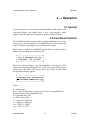
3.1 General
Two user interfaces are associated with the Handheld. Aside from its own
front panel display and controls, there is also a host interface, which
implies a software application running as a Windows 98/2K/XP task.
3.2 Front Panel Controls
The Handheld includes a built-in battery charger/eliminator that is active
whenever AC power is available. The Handheld power switch controls the
supply of battery (and charger) power to its internal circuitry.
When power is applied, the Handheld display shows a welcome banner
while it is busy waking up. It looks like this:
+------------------------+
| LS-11 Simulator V2.01c |
| Lumistar, Inc (c)2005 |
+------------------------+
While the welcome display is up, the Handheld is retrieving the PCM
format and transmitter information of record from non-volatile memory
and placing it into effect. This process takes two or three seconds. Then
the operational display appears:
+------------------------+
|nnnnnnnn qrrr.sM Dev=ttt|
|F:uuuuukHz-vwdBm xxx yyy|
+------------------------+
Where:
n = format name
qrrr.s = freq (500 kHz steps.) q is not a user field. It is controlled by the
frequency limits of the supplied RF head.
ttt = deviation (009..700)
u = PMF select in kHz
v = output level 10dB step
w = output level 5dB step.
xxx = "PCM" or "PRN"
yyy = "INT" or "EXT"
September 2006
3-1
Lumistar
Lumistar Portable Test Transmitter
Operation
3.2.1 Keypad
A keypad with four arrow keys manipulates the display. The display
cursor position is indicated by an underscore. Whenever the Handheld is
not busy processing input, the cursor character winks continuously.
That means almost always, except when the Handheld is loading a new
format selection from internal storage, or when the host interface receives
a command to save the present new format. That process causes the blink
to stop for several seconds.
Each legitimate position for the cursor is a "field." The cursor right and
left arrow keys move the cursor cyclically from one field to the next. The
cursor up and down arrow keys cyclically change the value of that field.
Except for the format name field, the resulting new value takes effect
immediately. A change to the format name does not take effect until the
cursor is moved. This will stop the cursor blink momentarily while new
information is being recovered and loaded. The PCM simulator is stopped
during this process.
3.2.2 RF Parameter Settings
A stored format definition has frequency, deviation, and Pre-Mod filter
settings embedded in it. These settings act like "smart thumbwheels."
When a new format is loaded, the settings embedded in the format
definition are placed into effect. You may alter these settings, and your
changes will be preserved across power cycles, until you choose a
different format definition.
RF frequency settings from the host interface or recalled from stored formats are
clamped within band edges. Frequencies set from the front panel are not. The
tuning range via front panel setting is 199.5MHz starting at some frequency
nn00.0MHz. It is possible to go out of band.
The output level setting is specifically NOT stored and recalled as part of
the format definition. It acts more like a regular thumbwheel and changes
only on command. The output level also differs in the behavior of the 5dB
step. Repeated 5dB steps "carry" into the 10dB digit unless the adjustment
is at the end of range.
3.2.3 PCM/PRN and INT/EXT
These display fields control the transmitter output. Selecting anything but
"PCM" causes the defined PCM data to be supplanted by a cyclic pseudonoise pattern using the same bit rate and output coding scheme. The
choices are 2047 (11) and 32,767 (15) bit patterns. A “+” indicates one
September 2006
3-2
Lumistar
Lumistar Portable Test Transmitter
Operation
error is introduced per pattern to yield a forced 4.885*10-4 or 3.05*10-5
BER.
Selecting "EXT" disconnects the PCM or PRN data from the transmitter
and connects the External Modulation input to it.
3.2.4 RF Output Control
A separate toggle switch controls the RF output. When power is applied,
this switch is disarmed until it is turned off. Thereafter, it is active.
When the RF switch is in the "Off" position, all RF circuitry in the
Handheld is disabled.
When the RF switch is turned "On" the RF synthesizer is enabled. The RF
LED indicator begins to blink. After a warm-up period, the LED stops
blinking and the RF output amplifier is turned on.
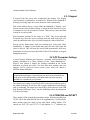
3.3 Baud Rate Recovery
Serial communications may be lost from the Handheld baud rate being set
incorrectly by inadvertent (or deliberate) writes to its configuration
EEPROM (See Table 4–7.) If this appears to have happened, tell your
software engineer to go back and read ¶4.1.11.1 again. Meanwhile, turn
the power switch off. While holding both the cursor left and right buttons
down, turn the power back on. Continue to hold the buttons until the
normal operating display appears. This "three-fingered-salute" forces the
baud rate to 9600 until power is cycled again.
3.4 LS11HandHeld.exe
On the host, LS11HandHeld provides a path to store PCM format and RF
setup information in the Handheld for later field use. To use it
meaningfully the Handheld serial port must be connected to a COM: port
on the host. Then launch the program by double-clicking its icon. All
normal operations of the program take place in a single window. The
window has a menu bar at the top, and three display pages with selection
tabs.
3.4.1 Menu Bar
The menu bar has three selections at the top.
3.4.1.1. File Menu
Clicking on File yields a dropdown with entries typical for Window
Applications. The dropdown selections refer to Handheld setups saved in
.ls11 files.
September 2006
3-3
Lumistar
Lumistar Portable Test Transmitter
Operation
If a .ls11 file is currently in use by the program, its name appears in the
bar at the very top of the window. File Save stores the current setup to that
selected file. If no file is open, this selection will default to a File Save As.
File Save As is for use when no file is currently in use, or when you want
to create a new .ls11 file or update an old one without overwriting the one
in effect. Selecting this opens a regular Windows popup allowing you to
choose a folder and filename. Performing this operation also makes the
new file the current file.
File Recall is exactly the opposite of File Save As. Selecting this opens a
regular Windows popup allowing you to choose a folder and existing
filename. Selecting a name causes the parameters from that file to be read
and makes it the current file.
Recalling a file has no effect on the Handheld itself.
3.4.1.2. Config Menu
Clicking on Config yields a single entry, Com Port. Selecting it pops a
window where a COM: port and parameters can be selected. The default
selections of 19200 baud, 8 bit characters with 1 stop and no parity should
never be changed for this application, but you will need to specify which
COM: port the Handheld is connected to. Click the "Accept" button to
close the window.
3.4.1.3 LoadAll
Selecting LoadAll transfers the simulator and transmitter settings of the
current setup to the Handheld and directs it to save them to its nonvolatile
storage. Before doing this, you must select a format number and edit the
format name if necessary in the format name area just below the menu bar.
3.4.2 Format Name Bar
The Handheld can store up to four different setups. This bar allows
selection of a format number and a name for that format. The format
number controls which format will be overwritten when a setup is written
to the Handheld. You are allowed to choose an eight-character name for
the format.
3.4.3 Handheld Screens
The application window has three tabs at the top. Setup pages for the PCM
Simulator and RF transmitter are displayed by clicking the appropriate tab.
The Query page displays display and configuration information read back
from the Handheld.
September 2006
3-4
Lumistar
Lumistar Portable Test Transmitter
Operation
3.4.4 Simulator Page
This page displays setup information for the Handheld PCM simulator.
Those previously exposed to our LDPS program and its relatives will see
something familiar because the Handheld simulator has capabilities
similar to the LS50 simulator except its minor frame length is limited to
8,191 words.
Format definition information is displayed in several white-outlined
boxes. To edit a parameter, put the cursor in the box and right-click. This
yields a menu where you can select a parameter and open an edit window
for it. Limits of a parameter are shown in the edit window.
I may be bold in presuming my readers are somewhat familiar with the
terminology associated with PCM formats.
Clicking the Word Attributes button opens a popup where data values for
common words can be entered or calculated. Also, if the format needs a
few oddball-length words, they can be identified here. If you make any
changes to word attributes, make sure you click "Apply" to close the
window.
Click the Load Simulator button to send the setup to the Handheld.
If you changed anything on the Transmitter setup page, make sure
you clicked Load Transmitter on that page before you click Load
Simulator on this page! Otherwise those changes will be lost as
soon as the Handheld user happens to change formats or cycle
power.
3.4.5 Transmitter Tab
This page displays setup information for the Handheld RF Transmitter.
The transmitter frequency is clamped and pre-mod filter selections within
the limits returned by the Handheld itself. Deviation is displayed as a
number between 9 and 299, each increment being equal to 10,000 Hz of
Peak Deviation .
Note there is an output level setting on this page, and you need to push the Load
Transmitter button to place it in effect. This is not part of the format definition, but
it doesn't really fit anywhere else.
3.4.6 Query Tab
When the Handheld application is launched it attempts to make contact
with a Handheld on the specified COM: port. If it connects, status
information is recalled from the Handheld and displayed here. If you're
September 2006
3-5
Lumistar
Lumistar Portable Test Transmitter
Operation
playing with buttons over there, you can click the Query LS11 Info button
here to refresh this display.
Format and Pre-Mod filter selection numbers on the screens are one-based, but
the (raw) query data reflects zero-based numbers.
September 2006
3-6
Lumistar
Lumistar Portable Test Transmitter
Programming Information
4 — Programming Information
4.1 Serial Communications
This chapter is targeted at any author developing a remote host application
for the Handheld. This is a description of the data transmitted over the host
interface.
Communication with the Handheld consists of exchange of short
"packets." I put "packet" in quotes because the definition of packet here is
unique. Each command from the host is a single packet. Once sent, the
host must wait for a response before sending anything else.
Packets are strings of ASCII characters. Each transaction is initiated with a
command packet from the host, and ends with receipt of a response packet
from the Handheld. With one exception, a command packet consists of
zero or more numeric parameters separated by spaces and ending with an
alphabetic command character. A response packet consists of zero or more
numeric values separated by spaces and ending with a carriage return
character. Alpha characters are not case-sensitive (except for the string
following "H".) All numbers in both directions are short (16-bit)
hexadecimal integers. Numbers in response packets will be zero-extended
to four digits. It is permissible, but not necessary, to do so in command
packets. If a parameter has more than four digits, the last four are used.
When the Handheld sees a command character it stops accepting input and
processes it. Any unused parameters are discarded, do not carry over to the
next command. The next command may be initiated as soon as a carriage
return ends the response packet.
All numbers are unsigned short hex integers. A number is a string of one
or more consecutive digits. (A..F and a..f are considered to be digits.)
In the command summary following, numbers are signified as nnnn. Some
commands take two parameters. A space is required to separate them. A
space after the last parameter is optional. One is shown one here only for
clarity.
All instances of "X" are ignored, so "0x123" is treated as 123.
September 2006
4-1
Lumistar
Lumistar Portable Test Transmitter
Programming Information
Some of the commands down the list are for our factory use. They are
included in this document mostly to make sure they are written down
someplace.
4.1.1 Select Format Number
Four positions are available to store a setup.
n N
selects a format where n is [0..3] If you intend to store a format you must
do this first.
4.1.2 Set Format Name
An eight-character name is associated with each format position, and
displayed on the panel when that format is selected. When creating setups
for a format,
Hzzzzzzzz
Sets the name where zzzzzzzz is a string of EXACTLY eight printable
ASCII characters. This command may be issued sometime between "N"
and "S" Avoid giving the same name to two different formats.
Character values in the range [0xA0..0xDF] are Katakan
4.1.3 Recall
To recall an existing format definition, where n is [0..3] Issue a "Y"
command. This will read the stored format back from nonvolatile memory
and place it into effect. This normally takes a few seconds:
n Y
4.1.4 Simulator Run/Halt
The simulator must be halted
0 R
to access memory or to store a format definition. It must be running
1 R
to generate a data stream.
September 2006
4-2
Lumistar
Lumistar Portable Test Transmitter
Programming Information
4.1.5 RF Parameters
Transmitter RF parameters are set by "G" commands. A well-formed G
command consists of two numeric parameters followed by an ASCII G.
The actual value is the first parameter. The second parameter is an index
to identify the first parameter:
nnnn 0 G
nnnn is Fc in units of 100kHz. This is rounded down to a 500kHz tuning
step. The RF synthesizer is immediately retuned if currently enabled. The
value becomes part of the present format definition if it is subsequently
saved.
nnnn 1 G
sets FM deviation to nnnn, a number in the range [0..999] I want to say it's
FM deviation in units of 10kHz but I cannot. A change takes effect
immediately. The value becomes part of the present format definition if it
is subsequently saved.
nnnn 2 G
nnnn in the set [0..3] selects a Pre-Mod filter. Cutoffs are NOT
predetermined; their values can be gotten by a "Q" query. The value
becomes part of the present format definition if it is subsequently saved.
nnnn 3 G
Set output level where nn is attenuation in units of 5dB. The value is not
part of the present format definition. It is saved from one power cycle to
the next, but is not updated if a new format is recalled. Making the value
bigger reduces the output level. Sane values are in the range 0 (+10dBm)
through 15 (<-60dBm.)
n 4 G
Enable (n=1) or disable (n=0) RF transmitter output.
This only works if the front panel RF switch is on. The idea was to
err on the side of not accidentally radiating.
n 5 G
Connect the simulator output (n=0) or the External Modulation BNC to
the RF transmitter input.
September 2006
4-3
Lumistar
Lumistar Portable Test Transmitter
Programming Information
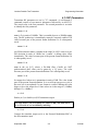
n 6 G
Select the PCM format or a PRN pattern as the simulator output:
n
0
1
2
3
4
Output
Defined PCM Format.
211-1 PRN Pattern.
211-1 PRN Pattern with one error/pattern.
215-1 PRN Pattern.
215-1 PRN Pattern with one error/pattern.
4.1.6 Clock Generator
The simulator clock generator is set by a "K" command. The clock rate is
a long integer split into two parameters where nnnn is the LSBs of the
clock rate and mmmm is the MSBs:
mmmm nnnn K
The simulator uses a Number Controlled Oscillator (NCO) to generate its
output clock. Exercise the following algorithm to get the NCO operating.
1. Start with the desired output bit rate.
2. If the logical AND of 0x0C and the value (chosen according to the
output code) written to the Code register (see below) is not zero, multiply
the rate by 2. Otherwise multiply by 1.
3. If the RATE bit in the Code register is set, multiply the rate by 2, but if
the 1/3 bit is also set, multiply the rate by 3.
4. Clamp the upper bound of the rate at 20,000,000. Neither the NCO nor
the simulator are certified reliable beyond that point.
5. If the result is 262,144 or greater, the DIV field in the Mode register
(Table 4–2) should be 00. Otherwise choose a DIV field and multiply the
rate by the "by" factor to get larger than 262,144 if possible. Cleave the
value into 16-bit halves for the command.
4.1.7 Mode Registers
The Handheld has three mode registers than must be set to complete the
PCM format definition. Undefined bits in these registers must be zero.
nnnn 0 T
Writes the Frame Start register. Bit assignments are shown in Table 4–1
September 2006
4-4
Lumistar
Lumistar Portable Test Transmitter
Programming Information
nnnn 1 T
Writes the Mode register. Bit assignments are shown in Table 4–2.
nnnn 2 T
Writes the Code register. Bit assignments are shown in Table 4–3.
4.1.8 Memory Access
The simulator uses two separate memories during its operation. Each
minor frame word location has an attribute word associated with, and a
data value to be output. The attribute table and common value tables are
each 16K (16-bit) words long. There are also tables of unique, sync, and
waveform values. These items are together in one 32K-word memory.
There are four pages of this memory, making 128K words total.
Juxtaposed with that, there are four pages of simulator frame attributes in
a separate memory. Each of these pages is 1K (8-bit) words.
The Handheld presents you with a 64K word address space. The word
attribute and data memory occupies locations 0..0x7FFF of that space. The
frame attribute memory occupies locations 0x8000.0x83FF. The
remainder of the space is unused. Two additional high-order address bits
are specified by the most recent Select Format Number ("N") or Recall
("Y") command.
Table 4–1. Frame Start Register (0 T)
Bit
9..0
12
Mnemonic
1STFRAME
SFUP
13
FAC
14
FCC
15
WDST
September 2006
Description
Frame number of the first minor frame in the major frame.
When set, causes minor frame numbers to increment in the course of
the major frame.
When set, words with the FSP attribute are inverted during oddnumbered minor frames.
When set, words with the FSP attribute are inverted during the first
minor frame of each major frame.
Always set this bit.
4-5
Lumistar
Lumistar Portable Test Transmitter
Programming Information
Table 4–2. Mode Register (1 T)
Bit
0
Mnemonic
CCITT
1
CRCEN
2
REVCRC
3
4
LSBF
CWS
6..5
DIV
8..10
BERT
Bit
3..0
Mnemonic
PCM CODE
5..4
RANDOMIZE
8
RATE
9
10
11
12
1/3
SWAP
INVERT
DIFF
Description
When set, causes a CRC-CCITT checkword to be calculated.
Otherwise CRC-16 is calculated. Has no meaning if CRCEN is clear or
if no CRC location is specified in the simulator word attributes.
When set, causes a CRC checkword to be calculated. Has no meaning
if no CRC location is specified in the simulator word attributes.
When set, causes a reversed CRC checkword to be calculated. Has no
meaning if CRCEN is clear.
When set, all simulator data is output LSB-first.
When cleared, simulator common output data is read from the common
data area in simulator memory. This means all words not pre-empted
by sync, unique, or waveform words. When set, the common data area
is ignored and all common output words have the value of the simulator
CWS memory location.
Selects a prescale ratio for the simulator clock: Choose one of:
00 – Divide by 1.
01 – Divide by 16.
10 – Divide by 256.
11 – Divide by 4096.
These bits were originally defined to set parameters for a PRN pattern
output. They are overridden by a “6 G” command.
Table 4–3. Code Register (2 T)
Description
PCM Output code. Choose one of the following:
0000 – NRZ-L
1001 – Inverted Bi-Phase-L
0001 – Inverted NRZ-L
1010 – Bi-Phase-M
0010 – NRZ-M
1011 – Bi-Phase-S
0011 – NRZ-S
1100 – DM-M
0100 – RZ
1101 – DM-S
0110 – Inverted RZ
1110 – M2
1000 – Bi-Phase-L
1111 – M2-S
RNRZ Randomizer Control. Choose one:
00 – Off
01 – RNRZ11
10 – RNRZ15
Enables the convolutional encoder. Causes output to be rate-1/2
encoded unless 1/3 is also set.
If RATE is set, causes output to be rate-1/3 encoded.
Swaps the G1 and G2 symbol when set.
Inverts the G1 symbol when set.
Enables differential encoding when set.
The simulator must be halted ("0 R" command) to access this memory.
Then the M and O (oh, not zero!) commands work.
nnnn aaaa M
September 2006
4-6
Lumistar
Lumistar Portable Test Transmitter
Programming Information
Writes hexadecimal nnnn to memory location aaaa. The frame attribute
memory is a single byte wide, so if aaaa > 0x7FFF only the lsb's of nnnn
have meaning.
aaaa O
Reads location aaaa and sends its hexadecimal value back in a return
packet. Normally this would only be needed to reverse-engineer an
existing stored format.
Memory accesses with the simulator running are ignored. (Reads return 0000.)
The data/word attribute memory is mapped as shown in Table 4–4.
Remember there are actually four such memories, selected by the format
number.
The frame attribute memory is strictly a lookup by minor frame number.
The part of the Reserved area between 0x2200 and 0x23FF is used
internally as an image of the frame attribute data.
The simulator Frame Attribute Memory is loaded with frame attributes
(believe it or not!) The Data and Word Attribute Memory holds both
output data and word attributes.
Each minor frame word location has an associated attribute word. The
attribute words are stored in data memory (See Table 4–4 for location.)
The attribute word is formatted per Table 4–5.
Each minor frame in the major frame has an attribute word in the Frame
Attribute memory, as shown in Table 4–6.
Data in the data areas is always right-aligned, regardless of word length or
bit ordering. However, for LSB-first data, the frame sync words need to be
bit-reversed to get the pattern to output properly. Also note the simulator
allocates and integral number of words to the frame sync pattern, and an
entire word to the SFID count, regardless of how many bits they actually
use. The simulator design provides support for formats using FCC or SFID
major frame correlation. There is no provision for URC formats per se. To
simulate a URC, you will need to pre-empt enough unique words to put
the URC pattern in the first minor frame.
September 2006
4-7
Lumistar
Lumistar Portable Test Transmitter
Programming Information
Table 4–4. Simulator Memory Map
Range
0x0000—0x1FFF
0x2000—0x2006
0x2007
0x2008—0x23FF
0x2400—0x27FF
0x2800—0x2BFF
0x2C00—0x2FFF
0x3000—0x33FF
0x3400—0x37FF
0x3800—0x3BFF
0x3C00—0x3FFF
0x4000—0x7FFF
0x8000—0x83FF
Definition
Common data values, lookup by word number mod 8192 (CWS=0.)
Unique word values, lookup by unique word number.
CWS data value meaningful only if CWS=1.
Reserved.
Frame Sync Pattern data, lookup by word number modulo 1024.
SFID data, lookup by minor frame number.
Waveform 1 data, lookup by minor frame number.
Waveform 2 data, lookup by minor frame number.
Waveform 3 data, lookup by minor frame number.
Waveform 4 data, lookup by minor frame number.
Waveform 5 data, lookup by minor frame number.
Word attributes, lookup by word number modulo.
Frame attributes.
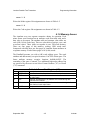
4.1.9 Save Format
Save Format copies the RF parameters and Mode Register values into the
parameter area, then copies the simulator RAM to flash memory. If the
same format is selected later, the flash is read and put into effect. The save
process normally takes about three or four seconds. If the simulator is not
halted, the save is ignored and the command returns immediately.
S
Table 4–5. Simulator Word Attributes
Bit
6..0
Mnemonic
WSPLn
7
CRCW
11..8 WL
14..12 I
15
EOF
Bit
6..0
Mnemonic
FSPLn
7
EOSF
Description
If FSPLn (n=0..5) is set for the current frame, substitute contents of
unique word n location for whatever other data would be output here.
Output the CRC checkword, starting with the first bit of this word. The
checkword output lasts for 16 bit periods, during which any other data
otherwise defined for output is discarded.
The word length in bits, less 1.
Data source for this word, unless overridden by CRC or unique word:
000 – Common data.
001 – Frame Sync Pattern data
010 – SFID data
011 – Waveform 1 data
100..111 – Waveform 2..5 data
Set to identify last word in minor frame.
Table 4–6. Simulator Frame Attributes
September 2006
Description
If WSPLn set for the current word, substitute contents of unique word n
location for whatever other data would be output here.
Set to identify last minor frame in the major frame.
4-8
Lumistar
Lumistar Portable Test Transmitter
Programming Information
4.1.10 Return Status
Two status query commands are included. Each returns a list of
hexadecimal numbers. Some things are repeated between the lists, they
return different copies of data that should match. The simulator does not
need to be halted to query. The "W" query was mostly written for our
development use.
Q
returns numbers n1 n2 n3 ... <carriage return> These are interpreted as:
n1 = Format Number of current format.
n2 = Minimum allowable center frequency in MHz
n3 = Maximum allowable center frequency in MHz (add 0.5)
n4 = Pre-Mod Filter #0 cutoff in kHz
n5 = Pre-Mod Filter #1 cutoff in kHz
n6 = Pre-Mod Filter #2 cutoff in kHz
n7 = Pre-Mod Filter #3 cutoff in kHz
n8 = VCO Reference divider. It's 10241. You don't care.
n9 = Center Frequency currently on screen.
n10 = Deviation value currently on screen.
n11 = Pre-Mod Filter selection currently on screen.
n12 = Output level setting currently on screen.
n13 = 0 if output is defined PCM stream, 1 if PRN pattern.
n14 = 0 if transmitter driven from simulator, 1 if external mod input.
n15 = 0 if front panel RF switch off, 1 if on.
W
returns numbers n1 n2 n3 ... <carriage return> These are interpreted as:
n1 = Fc currently on screen.
n2 = Deviation currently on screen.
n3 = PMCO Selection currently on screen.
n4 = Clock Rate MSBs.
n5 = Clock Rate LSBs.
n6 = Frame Start Register.
n7 = Mode Register.
n8 = Code Register.
n9..n12 = Format name. BIG-ENDIAN (msb of n9 is first char.)
4.1.11 Configuration EEPROM
Besides the storage of formats the Handheld has another nonvolatile
memory for storage of configuration and calibration data. Locations
[0..13] are the values returned by a "Q" query. Location 15 is the firmware
September 2006
4-9
Lumistar
Lumistar Portable Test Transmitter
Programming Information
revision number. Normally a user application would not need these
commands, but locations [16..31] potentially have utility in that they hold
the names of the four format definitions currently stored, in the same
format as the format name returned by "W" The simulator does not need
to be halted for these accesses.
aaa I
Returns value of location aaa.
nnnn aaa L
writes nnnn to location aaa.
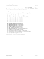
4.1.11.1 Options
Location 14 holds option information. At this writing, the usual factory
default for this location is 0x05FA, interpreted as shown in Table 4–7.
Table 4–7. EEPROM[14] Options
Bit
7..0
Mnemonic
BAUD
8..11
12
XMITEN
13..15
Description
Sets baud rate for serial communictions after the next time power is
applied. The usual default value is 0xFA for 19.2k baud. Values not in
the following list are nonsense:
0x40 – 600
0xF4 – 9600
0xA0 – 1200
0xFA – 19.2k
0xD0 – 2400
0xFD – 38.4k
0xE8 – 4800
0xFE – 115.2k
Reserved.
If zero, the RF switch is disarmed at power on, meaning the RF circuitry
is disabled until the switch is turned off and back on. Setting this bit
arms the switch.
Reserved.
4.1.12 Direct D/A Write
Two digital/analog converters are used in the Handheld. A command was
needed to write deviation (m=0) and attenuation (m=1) values to them for
calibration.
nnnn m V
September 2006
4-10
Lumistar
Lumistar Portable Test Transmitter
LS11Q
5 — LS11Q
5.1 General
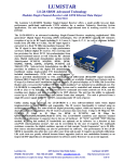
The LS11Q is based on the LS11 “Handheld” design but incorporates a
Quasonix QSX-VST RF Transmitter module, which results in a number of
detail differences summarized in this chapter. Items not mentioned are
identical to the LS11.
Specifications not listed here are identical to the LS11. See Chapter 1.
Table 5–1. LS11Q Specifications
Power Dissipation
Battery Capacity
RF Band
Modulation Type
Modulation Source
Output Power
Baseband Output Filter
FM Deviation
Less than 25 watts.
tbd, but shorter than LS11
S-Band (2200-2394.5MHz.)
Wideband FM, SOQPSK, MHCPM
PCM Simulator or Front-Panel TTL Data/Clock input
? to +10dBm Max (approximate) in 5dB steps
Eight selectable 4-Pole Bessel Filters, F1 points 0.5MHz,
1MHz, 2MHz, 4MHz, 6MHz, 8MHz, 10MHz, 15MHz.
Determined by data rate.
5.2 LS11Q Front Panel I/O
Six BNC connectors are provided.
External modulation is expected at TTL levels, and a TTL-level clock is
required.
Four Test outputs are provided.
The Baseband output is a bipolar PCM output. This signal passes through
the selected baseband output filter (unlike the LS11, this filter has no
effect on the RF signal.
The Clock and Data outputs are TTL levels and can be connected to a
PCM decommutator or such device for test purposes. For NRZ-type codes
the clock is at bit rate. For Bi-Phase and Miller codes the clock is at twice
bit rate.
September 2006
5-1
Lumistar
Lumistar Portable Test Transmitter
LS11Q
5.3 LS11Q Operation
The LS11Q front panel operation is the same as the LS11 except as noted
below. When power is applied, the LS11Q display shows a welcome
banner while it is busy waking up. It looks like this:
+------------------------+
| LS-11Q Simulator V3.00c|
| Lumistar, Inc (c)2006 |
+------------------------+
The LS11Q may not recover properly from a brief power cycle. If this
occurs the welcome banner will stay up. To recover, turn the power switch
off for at least five seconds.
The LS11Q does not provide FM deviation control. Deviation is
automatically set by the RF module. In its place, the RF transmit mode is
displayed as PCMFM, SOQPSK, or MHCPM.
The LS11 “warm-up” period during which the RF Transmit LED blinks is
eliminated. The Quasonix RF generator does not need it.
In a Baud Rate Recovery state (see ¶3.3) the RF output is disabled until
power is cycled again.
5.4 LS11Q Programming Information
Most of the programming information is identical except as noted. An
LS11Q can be identified by a query to the firmware revision number:
0F I
This will return a four-digit hexadecimal number in ASCII. Values in the
range 0x3nnn identify an LS11Q.
5.4.1 LS11QRF Parameters
nnnn 1 G
sets the Transmitter mode, encoded as: 0: FM, 1: SOQPSK, 2: MHCPM.
nnnn 2 G
nnnn in the set [0..7] selects a Baseband Output filter. Note this is not a
Pre-mod filter, it affects only the front-panel baseband output. The value
becomes part of the present format definition if it is subsequently saved.
September 2006
5-2
Lumistar
Lumistar Portable Test Transmitter
LS11Q
5.4.2 LS11Q Status Query
The LS11Q returns a different and longer list of parameters.
Q
returns numbers n1 n2 n3 ... <carriage return> These are interpreted as:
n1 = Format Number of current format.
n2 = Minimum allowable center frequency in MHz
n3 = Maximum allowable center frequency in MHz (add 0.5)
n4 = Baseband Output Filter #0 cutoff in kHz
n5 = Baseband Output Filter #1 cutoff in kHz
n6 = Baseband Output Filter #2 cutoff in kHz
n7 = Baseband Output Filter #3 cutoff in kHz
n8 = Baseband Output Filter #4 cutoff in kHz
n9 = Baseband Output Filter #5 cutoff in kHz
n10 = Baseband Output Filter #6 cutoff in kHz
n11 = Baseband Output Filter #7 cutoff in kHz
n12 = Center Frequency currently on screen.
n13 = RF Transmit mode currently on screen.
n14 = Baseband Output Filter selection currently on screen.
n15 = Output level setting currently on screen.
n16 = 0 if output is defined PCM stream, 1 if PRN pattern.
n17 = 0 if transmitter driven from simulator, 1 if external mod input.
n18 = 0 if front panel RF switch off, 1 if on.
and maybe n19 = Celsius RF transmitter temperature.
September 2006
5-3
Lumistar