1
Institutionen för datavetenskap
Department of Computer and Information Science
Master’s Thesis
An LLVM Back-end for REPLICA
Code Generation for a Multi-core VLIW
Processor with Chaining
by
Daniel Åkesson
LIU-IDA/LITH-EX-A-12/007-SE
2012-05-08
Linköpings universitet
SE-581 83 Linköping, Sweden
Linköpings universitet
581 83 Linköping
Linköping University
Department of Computer and Information Science
Master’s Thesis
An LLVM Back-end for REPLICA
Code Generation for a Multi-core VLIW
Processor with Chaining
by
Daniel Åkesson
LIU-IDA/LITH-EX-A-12/007-SE
2012-05-08
Supervisor: Erik Hansson
Examiner: Christoph Kessler
Avdelning, Institution
Division, Department
Datum
Date
PELAB
Department of Computer and Information Science
Linköpings universitet
SE-581 83 Linköping, Sweden
Språk
Language
Rapporttyp
Report category
ISBN
� Svenska/Swedish
� Licentiatavhandling
ISRN
� Engelska/English
� Examensarbete
� C-uppsats
� D-uppsats
� Övrig rapport
�
2012-05-08
—
LIU-IDA/LITH-EX-A-12/007-SE
Serietitel och serienummer ISSN
Title of series, numbering
—
�
URL för elektronisk version
http://www.ep.liu.se
Titel
Title
Ett LLVM Back-end för REPLICA
Kodgenerering för en Flerkärning VLIW Processor med Kedjade Instruktioner
An LLVM Back-end for REPLICA
Code Generation for a Multi-core VLIW Processor with Chaining
Författare Daniel Åkesson
Author
Sammanfattning
Abstract
REPLICA is a PRAM-NUMA hybrid architecture, with support for instruction
level parallelism as a VLIW architecture. REPLICA can also chain instructions
so that the output from an earlier instruction can be used as input to a later
instruction in the same execution step.
There are plans in the REPLICA project to develop a new C-based programming language, compilers and libraries to speed up development of parallel programs. We have developed a LLVM back-end as a part of the REPLICA project
that can be used to generate code for the REPLICA architecture. We have also
created a simple optimization algorithm to make better use of REPLICAs support
for instruction level parallelism. Some changes to Clang, LLVMs front-end for
C/C++/Objective-C, was also necessary so that we could use assembler in-lining
in our REPLICA programs.
Using Clang to compile C-code to LLVMs internal representation and LLVM
with our REPLICA back-end to transform LLVMs internal representation into
MBTACa assembler.
Nyckelord
Keywords
REPLICA, LLVM, PRAM, compilers, MBTAC
a MBTAC
is the processor in the REPLICA architecture
Abstract
REPLICA is a PRAM-NUMA hybrid architecture, with support for instruction
level parallelism as a VLIW architecture. REPLICA can also chain instructions
so that the output from an earlier instruction can be used as input to a later
instruction in the same execution step.
There are plans in the REPLICA project to develop a new C-based programming language, compilers and libraries to speed up development of parallel programs. We have developed a LLVM back-end as a part of the REPLICA project
that can be used to generate code for the REPLICA architecture. We have also
created a simple optimization algorithm to make better use of REPLICAs support
for instruction level parallelism. Some changes to Clang, LLVMs front-end for
C/C++/Objective-C, was also necessary so that we could use assembler in-lining
in our REPLICA programs.
Using Clang to compile C-code to LLVMs internal representation and LLVM
with our REPLICA back-end to transform LLVMs internal representation into
MBTAC1 assembler.
Sammanfattning
REPLICA är en VLIW liknande PRAM-NUMA arkitektur, med möjlighet för att
kedja ihop instruktioner så att resultat från tidigare instruktioner kan användas
som indata till nästa instruktion i samma exekveringssteg.
Inom REPLICA projetet finns planer på att utecklar ett nytt C-baserat programmeringsspråk, kompilatorer och bibliotek för att snabbba upp utvecklingen av
parallella program. Som en del av REPLICA projektet har vi utvecklat ett kompilator back-end för LLVM som kan användas för att generera kod till REPLICA. Vi
har även utvecklat en enklare optimerings algoritm för att bättre utnyttja REPLICAs förmåga för instruktions parallelisering. Vi har även gjort ändringar i Clang,
LLVMs front-end för C/C++/Objective-C, så att vi kan använda inline assembler
i REPLICA program.
Med Clang kan man kompilera C-kod till LLVMs interna representation som
i sin tur genom LLVM och REPLICA back-end kan omvandlas till MBTAC3 assembler.
1 MBTAC
3 MBTAC
is the processor in the REPLICA architecture
är processorn i REPLICA
v
Acknowledgments
To Erik Hansson for supervision and comments on this thesis.
To Martti Forsell for comments on this thesis.
This project was funded by VTT.
vii
Contents
1 Introduction
1.1 Motivation
. . . . . . . . . . . . . . . . . . . . . . . . . . . . . . .
2 Background
2.1 PRAM Model of computation . . . .
2.2 REPLICA . . . . . . . . . . . . . . .
2.2.1 REPLICA Language System
2.2.2 REPLICA Architecture . . .
2.3 LLVM . . . . . . . . . . . . . . . . .
2.3.1 Clang . . . . . . . . . . . . .
2.3.2 LLVM passes . . . . . . . . .
2.3.3 Back-ends . . . . . . . . . . .
2.3.4 LLVM internal representation
2.3.5 TableGen . . . . . . . . . . .
2.4 Alternative Compilers . . . . . . . .
2.5 Related work . . . . . . . . . . . . .
1
2
.
.
.
.
.
.
.
.
.
.
.
.
.
.
.
.
.
.
.
.
.
.
.
.
.
.
.
.
.
.
.
.
.
.
.
.
.
.
.
.
.
.
.
.
.
.
.
.
.
.
.
.
.
.
.
.
.
.
.
.
.
.
.
.
.
.
.
.
.
.
.
.
.
.
.
.
.
.
.
.
.
.
.
.
.
.
.
.
.
.
.
.
.
.
.
.
.
.
.
.
.
.
.
.
.
.
.
.
.
.
.
.
.
.
.
.
.
.
.
.
.
.
.
.
.
.
.
.
.
.
.
.
.
.
.
.
.
.
.
.
.
.
.
.
.
.
.
.
.
.
.
.
.
.
.
.
.
.
.
.
.
.
.
.
.
.
.
.
.
.
.
.
.
.
.
.
.
.
.
.
.
.
.
.
.
.
.
.
.
.
.
.
3
4
4
5
9
16
17
17
17
18
19
20
22
3 Implementation
3.1 Code generation . . . . . . . . . . . . .
3.1.1 Instruction selection . . . . . . .
3.1.2 SSA based optimization . . . . .
3.1.3 Register allocation . . . . . . . .
3.1.4 Prolog/Epilog code insertion . .
3.1.5 Late machine code optimizations
3.1.6 Code emission . . . . . . . . . .
3.2 Target machine description . . . . . . .
3.2.1 Sub-targets . . . . . . . . . . . .
3.3 Registers . . . . . . . . . . . . . . . . . .
3.4 Instructions . . . . . . . . . . . . . . . .
3.4.1 Calling conventions . . . . . . . .
3.5 Assembly printer . . . . . . . . . . . . .
3.6 Clang basic target information . . . . .
.
.
.
.
.
.
.
.
.
.
.
.
.
.
.
.
.
.
.
.
.
.
.
.
.
.
.
.
.
.
.
.
.
.
.
.
.
.
.
.
.
.
.
.
.
.
.
.
.
.
.
.
.
.
.
.
.
.
.
.
.
.
.
.
.
.
.
.
.
.
.
.
.
.
.
.
.
.
.
.
.
.
.
.
.
.
.
.
.
.
.
.
.
.
.
.
.
.
.
.
.
.
.
.
.
.
.
.
.
.
.
.
.
.
.
.
.
.
.
.
.
.
.
.
.
.
.
.
.
.
.
.
.
.
.
.
.
.
.
.
.
.
.
.
.
.
.
.
.
.
.
.
.
.
.
.
.
.
.
.
.
.
.
.
.
.
.
.
.
.
.
.
.
.
.
.
.
.
.
.
.
.
.
.
.
.
.
.
.
.
.
.
.
.
.
.
.
.
.
.
.
.
.
.
.
.
.
.
.
.
23
25
25
26
26
27
27
27
27
29
30
32
32
33
34
ix
.
.
.
.
.
.
.
.
.
.
.
.
x
Contents
4 Optimization
4.1 Instruction splitter . . . . . . . . . . . . . . .
4.2 Dependence DAG . . . . . . . . . . . . . . . .
4.3 Optimizations for instruction level parallelism
4.3.1 Datastructures and algorithm details .
4.3.2 Similarities to task scheduling . . . . .
4.3.3 Time complexity . . . . . . . . . . . .
4.3.4 Practical example . . . . . . . . . . .
.
.
.
.
.
.
.
.
.
.
.
.
.
.
.
.
.
.
.
.
.
.
.
.
.
.
.
.
.
.
.
.
.
.
.
.
.
.
.
.
.
.
.
.
.
.
.
.
.
.
.
.
.
.
.
.
.
.
.
.
.
.
.
.
.
.
.
.
.
.
.
.
.
.
.
.
.
.
.
.
.
.
.
.
35
35
36
37
39
40
40
42
5 Evaluation
5.1 Parallel max/min value
5.2 Parallel array sum . . .
5.3 Threshold image filter .
5.4 Blur image filter . . . .
5.5 Discussion . . . . . . . .
.
.
.
.
.
.
.
.
.
.
.
.
.
.
.
.
.
.
.
.
.
.
.
.
.
.
.
.
.
.
.
.
.
.
.
.
.
.
.
.
.
.
.
.
.
.
.
.
.
.
.
.
.
.
.
.
.
.
.
.
45
45
48
50
52
55
.
.
.
.
.
.
.
.
.
.
.
.
.
.
.
.
.
.
.
.
.
.
.
.
.
.
.
.
.
.
.
.
.
.
.
.
.
.
.
.
.
.
.
.
.
.
.
.
.
.
.
.
.
.
.
.
.
.
.
.
6 Conclusion
57
7 Future work
59
A Building and using the compiler
61
B Assembler Language
B.1 Memory unit sub-instructions . . . . . . .
B.2 Write back subinstructions . . . . . . . . .
B.3 ALU subinstructions . . . . . . . . . . . .
B.4 Immediate operand input subinstructions
B.5 Compare unit subinstructions . . . . . . .
B.6 Sequencer subinstructions . . . . . . . . .
.
.
.
.
.
.
.
.
.
.
.
.
.
.
.
.
.
.
.
.
.
.
.
.
.
.
.
.
.
.
.
.
.
.
.
.
.
.
.
.
.
.
.
.
.
.
.
.
.
.
.
.
.
.
.
.
.
.
.
.
.
.
.
.
.
.
.
.
.
.
.
.
.
.
.
.
.
.
.
.
.
.
.
.
63
63
67
67
69
69
69
C Benchmark code
C.1 Makefile . . . . . . . .
C.2 Initialization function
C.3 pmaxmin . . . . . . .
C.4 psum . . . . . . . . . .
C.5 threshold . . . . . . .
C.6 blur . . . . . . . . . .
.
.
.
.
.
.
.
.
.
.
.
.
.
.
.
.
.
.
.
.
.
.
.
.
.
.
.
.
.
.
.
.
.
.
.
.
.
.
.
.
.
.
.
.
.
.
.
.
.
.
.
.
.
.
.
.
.
.
.
.
.
.
.
.
.
.
.
.
.
.
.
.
.
.
.
.
.
.
.
.
.
.
.
.
70
70
71
73
74
75
77
Bibliography
.
.
.
.
.
.
.
.
.
.
.
.
.
.
.
.
.
.
.
.
.
.
.
.
.
.
.
.
.
.
.
.
.
.
.
.
.
.
.
.
.
.
.
.
.
.
.
.
.
.
.
.
.
.
.
.
.
.
.
.
.
.
.
.
.
.
79
Chapter 1
Introduction
This thesis project is part of the REPLICA1 project. The focus has been to create
a compiler back-end that generates assembler code for the REPLICA architecture.
This compiler back-end is only a part in what is to become a whole tool-chain for
developing programs for the REPLICA architecture, including a high level language specialized for creating parallelized programs, a C-based baseline language
described in this report, an assembler language (that this back-end generates code
in), support libraries and a simulator for the architecture to run programs on.
The REPLICA architecture is a realization of the PRAM, Parallel Random
Access Machine, which is the ideal parallel computer. PRAM is based on the
normal Random Access Machine, which consists of a memory and one processor,
but with more than one processors sharing the same memory [17]. REPLICA
does not follow the definition of a PRAM exactly as it also has a private memory
module attached to each processor.
MBTAC, the processor in the REPLICA architecture, can have several functional units so it is a VLIW2 architecture. This creates some opportunities for
instruction level parallelism, ILP, i.e. we can run several instructions in parallel.
So we have also adapted a simple optimization algorithm for finding instructions
that can be executed in parallel and relocating them so they are.
LLVM, the Low Level Virtual Machine compiler framework, was given as a
recommendation to implement a compiler back-end for. We investigated alternatives but in the end LLVM was chosen mainly because it is popular, has many
users and industry support making it unlikely to cease developing and disappear.
First we will give some background information on the REPLICA project and
LLVM in chapter 2. Then we will describe the implementation in chapter 3. How
the optimization is done is described in chapter 4. In chapter 5 we run some
benchmark programs and analyze the results. At last, chapter 6 contains some
general thoughts on the project and possible future work.
1 Project full name: Removing Performance and Programmability Limitations of Chip Multiprocessor Architectures
2 Very Large Instruction Word
1
2
1.1
Introduction
Motivation
With a high level programming language it is often easier to write large and/or
complex programs than with a target specific low level language (for example an
assembler language). A compiler is needed to convert the high level language into
a low level language.
Optimization of the generated code is needed to utilize the potential speedup
from the combination of instruction level parallelism and thread level parallelism
possible on the REPLICA architecture. This is an interesting problem with many
solutions; we have chosen a simpler greedy algorithm for optimizing programs in
this project.
Chapter 2
Background
The REPLICA project is developing a configurable emulated shared memory machine architecture [24]. As a proof of concept an FPGA based prototype machine,
a new programming language, compilation- and optimization-tools and sample
programs are being developed [24].
The REPLICA language has a C-style syntax with some modifications [24].
Code written in REPLICAs language is first to be compiled into C which is in
turn compiled into MBTAC assembler [24].
A compiler is a computer program that reads a program in one language and
translates it to another language [9]. A compiler usually works in several phases
(the number of phases varies between compilers) [9]. As an example [9] uses the
following compiler phases:
• Lexical analyzer: Reads the source program and outputs a stream of tokens.
When the lexical analyzer encounter for example a variable declaration it
stores information such as name and type in the symbol table.
• Syntax analyzer: Reads the tokens a creates a syntax tree where each interior node in the tree represents an operation and the children of that node
represents the arguments to the operation.
• Semantic analyzer: Uses the syntax tree and symbol table to check that the
program is consistent with the language definition.
• Intermediate code generator: Compilers usually generate a machine like intermediate representation of the program. The intermediate representation
should be easy to produce and to translate into the target machine.
• Machine independent code optimizer: In this phase the compiler tries to
optimize the intermediate code. The goal is to get better target code.
• Code generator: This step translates the intermediate code into the target
language.
3
4
Background
• Machine dependent code optimizer: In this phase the compiler tries to do
further optimizations. For example in our case scheduling instructions that
can be executed in parallel.
We have in this project used the LLVM compiler framework to construct a
compiler for REPLICA.
2.1
PRAM Model of computation
PRAM, Parallel Random Access Machine, is a generalization of the RAM (Random
Access Machine) model [17]. Instead of just one processor connected to memory
let us have n processors [17]. In each execution step all processors perform one
instruction this could be either memory access, ALU operations, comparisons and
branch instructions [17]. Because several processors can perform memory accesses
simultaneously, several processors can also try to access the same memory cell
simultaneously. There exists many PRAM variants for how such memory accesses
are handled [17].
• EREW, Exclusive Read Exclusive Write, several processors may not read or
write from/to the same memory cell simultaneously [17].
• CREW, Concurrent Read Exclusive Write, several processors may read from
the same cell simultaneously. But only one processor is allowed to write to
the same memory cell in each step [17].
• CRCW, Concurrent Read Concurrent Write, several processors may read
or write to same memory cell in each step. What happens when several
processors write to the same cell varies between CRCW PRAM sub-variants
[17].
NUMA, Non-Uniform Memory Access, consists of multiple processors with a
local memory bank each [13]. All processors are interconnected with a communication network so that non-local memory access will take longer time [13].
REPLICA implements the PRAM-NUMA model of computation that has P
processors grouped as PTp processor groups [13, 24]. All processors are connected
to a shared memory as a PRAM would and each group of processors are connected
their own interconnected local memory block as in NUMA [13, 24]. REPLICA also
uses a arbitrary CRCW memory model, all threads participating in a concurrent
read will obtain the same result and for all threads participating in a concurrent
write some arbitrary thread will write to the memory location [15]. REPLICAs
multi-prefix instructions can be used to control concurrent operations on any location in the shared memory, see section 2.2.1.
2.2
REPLICA
REPLICA is the short name for Removing Performance and Programmability
Limitations of Chip Multiprocessor Architectures [24]. The project aims to develop
2.2 REPLICA
5
a complete language system from high-level programming language to assembler,
support libraries and hardware to run the programs on [24].
2.2.1
REPLICA Language System
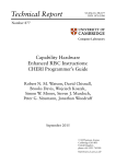
The REPLICA language system is to contain a high level parallel programming
language, support libraries, a low level baseline language, unoptimized MBTAC
assembler for a minimal REPLICA configuration and optimized MBTAC assembler
for a specific REPLICA configuration [24], see Figure 2.1.
Figure 2.1. The REPLICA language system
REPLICA Language
The REPLICA language is supposed to have a C-style syntax with various extensions. It uses the same parallelism style as the e-language [24], the e-language lets
the programmer declare shared and private variables, synchronous control structures and mix both a synchronous and asynchronous programming style [12]. The
REPLICA language specification is still in development so it will not be used in
this thesis.
Baseline Language
The baseline language is C with e-/fork-style parallelism [24]. Code written in the
baseline language can be compiled with LLVM together with the REPLICA backend [24]. The current implementation of the baseline language is basically C with
assembler in-lining and macros for handling REPLICAs multi-prefix instructions.
Figure 2.2 shows a program that calculates the sum of an array with 8096 integers. Note that shared variables end with a ’_’ and built-in macros and variables
start with an ’_’.
6
1
2
3
4
5
6
7
8
9
10
11
12
13
14
15
16
17
18
19
20
21
Background
#i n c l u d e " r e p l i c a . h "
#d e f i n e SIZE 8 0 9 6 ;
i n t a r r a y [ SIZE ] ; /∗ p r i v a t e a r r a y w i t h SIZE e n t r i e s ∗/
i n t sum_ = 0 ; /∗ s h a r e d v a r i a b l e ∗/
i n t main ( )
{
unsigned i n t i ;
_ s t a r t _ t i m e r ; /∗ Timer used f o r benchmarking ∗/
f o r ( i = _thread_id ; i < SIZE ; i += _number_of_threads )
{
asm ( "MADD0␣%0␣%1" : /∗ no o u t p u t ∗/
: " r " ( a r r a y [ i ] ) , " r " (&sum_)
: /∗ no c l o b b e r ∗/ ) ;
}
_ s y n c h r o n i z e ; /∗ Wait f o r a l l t h r e a d s ∗/
_end_timer ; /∗ Stop t h e benchmarking t i m e r ∗/
_ e x i t ; /∗ I s s u e an e x i t t r a p t o h a l t t h e program ∗/
return 0 ;
}
Figure 2.2. Baseline language example.
Shared and private variables
The simulator, IPSMSimX86, sees data labels ending with a ’_’ as data that
belongs in the shared memory so to be able to differentiate between a shared and
a private variable in a C program a simple naming convention was used. The
names of shared variables need to end with a ’_’ because then the variables label
name in the generated assembler code will also end with a ’_’ and IPSMSimX86
will see that variable as shared, see Figure 2.3 for how shared and private variables
are declared.
1
2
i n t shared_var_ = 0 ; /∗ A s h a r e d v a r i a b l e ∗/
i n t p r i v a t e _ v a r = 0 ; /∗ A p r i v a t e v a r i a b l e ∗/
Figure 2.3. Baseline language example.
Each thread has a copy of a private variable so in Figure 2.3 where private_var
is set to zero each thread running the program with this declaration will get its
own version of private_var in its own private memory space and this variable
will be set to zero.
The shared variable, shared_var, on the other hand will be stored in the shared
memory space so all threads running the program with this declaration will access
the same instance of the shared variable shared_var.
2.2 REPLICA
7
Built-in variables
There are some built-in variable for accessing information such as thread id and
total number of threads. As simple naming convention that we used is to let all
built-in REPLICA specific variables and macros start with an ’_’. This helps us
differentiate between generic library functions and machine specific functions.
Table 2.1. Built-in variables containing information about the currently running configuration.
Name
_private_space_start
Description
Start of the current threads private memory space.
Also stored in register R32
The current threads id number.
The total number of threads.
_thread_id
_number_of_threads
Built-in macros
IPSMSimX86, the simulator used to simulate the REPLICA architecture, has some
built-in traps for using timers and halting the program. By naming convention
these macros should start with an ’_’.
Name
_start_timer
_stop_timer
_exit
Description
Issues an OP 176 TRAP O0 that starts the simulator’s timer
Issues and OP 180 TRAP O0 that stops the simulator’s
timer
Issues an OP 0 TRAP O0 that halts the simulator
Library functions
Some help functions that we created during development of the back-end ended up
in this library. The longterm goal is that this should be compiled into a runtime
library that can be used to replace the current ECLIPSE runtime library.
types.h
This header only defines different types with more obvious size information.
• 8, 16 and 32 bit unsigned integers (uint8,uint16,uint32).
• 8, 16 and 32 bit signed integers (int8,int16,int32).
• A size type (size_t).
8
Background
string.h
Currently only contains an implementation of memcpy.
Name
memcpy(void*, const void*, size_t)
Description
Copies data.
stdlib.h
Allocating memory with malloc does not currently work because the statically and
dynamically allocated memory collides in the shared memory space so they end up
overwriting each other. Event though its called malloc and free memory allocation
currently only works in shared memory.
Name
void init_mem()
void* malloc(size_t)
void free(void*)
Description
Initializes the allocated memory list.
Allocates memory in the shared memory space.
Frees allocated memory.
MBTAC Assembler
The MBTAC processor lets us chain sub-instructions so that we can use the output
of one sub-instruction as an input operand for the next sub-instruction [24]. There
are different types of sub-instructions dependending on which functional unit it
uses. In our REPLICA configurations we have the following sub-instruction types.
See appendix B for descriptions of each sub-instruction.
• Memory unit sub-instructions: Load, store and multi-prefix instructions.
• ALU sub-instructions: Instructions like add and subtract etc. and also compare instructions where the result is stored in a register.
• Compare unit: Compare sub-instructions where the result sets status register
flags. There is always only one compare unit.
• Sequencer: Program flow altering sub-instructions i.e. jump and branch.
There is always only one sequencer.
• Operand: One sub-instruction only. Used to load a constant or label etc.
into an operand slot.
• Writeback: Also only one sub-instruction. Used to copy register contents.
When writing code for MBTAC, sub-instructions that are to be issued in the
same execution step are written on the same line, see the code example in Figure
2.4.
2.2 REPLICA
1
2
OP0 16
OP0 2
9
ADD0 O0 , R1
MUL0 O0 , R2
LD0 A0
WB1 A0
ST0 A0 , R1
WB2 M0
Figure 2.4. MBTAC assembler example.
Line 1 in example 2.4 calculates an address by adding 16 to R1, the result is
stored in A0 and is used to load a word. The calculated address is then copied
to R1 and the loaded word is copied to R2 with a WBn sub-instruction (where n
is the destination register). In the next execution step R2 is multiplied by 2 and
the result of that multiplication is stored to the memory address contained in R1.
These two lines also show how chaining works because each line is executed in one
step per thread. The result from previous sub-instructions must thus be used in
the next sub-instruction in the same clock cycle.
Multi-prefix instructions are special instructions where several threads can interact with the same memory cell simultaneously. This is achieved by a so-called
“active memory unit” where the memory unit contains a simple ALU so that ALU
operations can be performed on the active memory cell i.e. the address we provide
to the multi-prefix instruction. An example of a multi-prefix operation is Figure
2.5 where all threads will add 1 to the memory cell pointed to by R1.
1
OP0 1 MADD0 O0 , R1
Figure 2.5. An add multi-prefix operation.
There are also assembler directives available both to control actions by the
simulator and for marking code and data sections. The compiler inserts directives
where needed in the generated code except for FILE, SAVE, DEFAULT and RANDOM
directives which are left to the user to insert where needed. See Table 2.2 [24].
2.2.2
REPLICA Architecture
REPLICA is a TOTAL ECLIPSE based architecture [24] that implements the
PRAM-NUMA model of computation [24]. A REPLICA can have a configurable
number of processors, threads and functional units (consisting of ALUs and other
functional units) [24].
A REPLICA has P MBTAC processors, each processor has Tp threads, F
functional units and R registers. The functional units are A ALUs, M memory
units (MU), one compare unit and one sequencer1 . We have been able to test our
compiler on simulated versions of the processor with the configurations given in
table 2.3.
We had access to three ideal PRAM configurations and two ECLIPSE configurations. The difference between them is that the ECLIPSE configurations are not
1 Handles
program flow altering instructions, like branch sub-instructions BNEZ.
10
Background
Table 2.2. REPLICA assembler directives.
Name
ALIGN n
ASCII str
BYTE n
DATA
DEFAULT
HALF n
PROC name
ENDPROC name
RANDOM
SPACE n
TEXT
WORD n
GLOBAL name
FILE filename
SAVE size filename
Description
Move the location to the next multiple of n
Place the string str in the data segment
Place a 8-bit byte with value n in the data segment
Mark the start of a data segment
Define a storage area in the data segment, which is filled
with ordinal words[24]
Place a 16-bit halfword with value n in the data segment
Declare the start of procedure name
Declare the end of procedure name
Define a storage area in the data segment, which is filled
with random words[24]
Reserve n bytes in the data segment
Mark the start of a code segment
Place 32-bit word with value n in the data segment
Declare a global variable or procedure with name name
Fill this memory location with data from filename
write size number of bytes from this location to filename
ideal PRAM so they are a bit slower (using more cycles) than the PRAM configurations. For the PRAM configurations we had 4, 16, and 64 processors with each
processor having 512 threads while the two ECLIPSE configurations both had 4
processors with 4 and 512 threads.
Table 2.3. REPLICA configuration names and number of processors/threads.
Name
Processors
ECLIPSE_CRCW4
T5-44e_SRAM_SA4
ECLIPSE_CRCW4
T5-44e_SRAM_SA4
PRAM-T5-44
512+
PRAM-T5-1616
512+
PRAM-T5-6464
512+
Threads
4
ALUs
1
Memory units
1
Registers
34
512
1
1
34
512
1
1
34
512
1
1
34
512
1
1
34
The memory space on the REPLICA architecture is divided between a dedicated program memory space, shared memory space and a thread private memory
2.2 REPLICA
11
space for each thread [24]. The simulator for the whole architecture, IPSMSimX86,
currently only works on Mac OS X. We had some problems with the current simulator and file encodings, even though both files are in UTF-8 the file generated
by our compiler lacks the internal file type signatures used by the simulator. We
solved this by copying the content of our generated assembler files into a file with
the correct flags set.
Simulator
For testing programs compiled for REPLICA we use a simulator, IPSMSimX86,
that was originally written for the ECLIPSE project [15] but also can be used for
running REPLICA programs. The simulator view is divided into several windows
showing what is going on in the simulated computer while executing our program.
The command window shows us a history of commands, see figure 2.6, that we
have issued to the simulator like loading a program or executing a program.
Figure 2.6. IPSMSimX86, command window showing a history of step thread (Step T)
commands.
The simulator uses the output window to print out error messages about the
assembler code we are trying to run. Messages are only printed when the simulator
tries to execute the part of the generated assembler code that contains the error
so the simulator must run the program to be able to find any errors in it. Possible
error messages are listed in table 2.4 [24].
Figure 2.7 shows the output window of the simulator. Output messages are
usually error messages but could also be information about issued traps and other
general information.
The window labeled with the currently loaded configuration, see Figure 2.8,
shows us the state and contents of registers in the simulated machine. When single
stepping a thread, processor or the whole machine, this window is updated in every
step, otherwise it only shows the content from when the machine was last halted.
12
Background
Table 2.4. IPSMSimX86 assembler error messages.
Number
101
102
103
104
105
106
107
108
109
110
111
112
114
115
116
117
Message
Illegal ALU number
Illegal memory bus number
Illegal memory bus number
Illegal register number
Illegal operand number
Illegal mnemonic
Missing directive
End of line ignored
Illegal label
Illegal label
Missing directive
End of line ignored
Symbol Table overflow
Unkown operand
Unkown instruction class
Program too large to fit in instruction memory
Figure 2.7. IPSMSimX86 output window.
The memory content window, see figure 2.9, is a bit hard to read, but it shows
the content of the complete memory in the current configuration. The memory
address to the first memory cell on a line is written on the left side, each row then
has 8 memory slots.
The code window, see figure 2.10, shows which instructions are currently executed, the numbers to the left of the marked line show how many threads are
2.2 REPLICA
13
Figure 2.8. IPSMSimX86 register contents window.
Figure 2.9. IPSMSimX86 memory contents window.
executing that line. All threads do not have to be executing the same line of code
as the program runs and when threads become more fragmented the numbers to
the left will decrease and spread out to other lines.
The global variables window, see figure 2.11, is very helpful when checking if
a program performs as expected. The memory content window is quite hard to
read and to locate the correct location to check the content of a variable. On the
other hand the global variables window shows the name address and content of
global variables making it perfect for checking the results from a program. The
only problem is that in the case of an array only the first couple of elements in
14
Background
Figure 2.10. IPSMSimX86 code window, the marked line is currently being executed
by 2048 threads.
the array are shown; if we want to get the whole array we are forced to dump the
array variable to a file.
Figure 2.11. IPSMSimX86, global variables and their contents.
Processor
MBTAC, short for Multi-bunched/threaded Architecture with Chaining, is a dual
mode VLIW architecture [24]. The two modes are PRAM and NUMA. In PRAM
mode each MBTAC has A ALUs, M memory units, M hash address calculation
units, a compare unit, a sequencer and R registers per thread [24]. On the other
hand in NUMA-mode processors can be configured to execute a common instruction stream and share their state among each other each other [24]. Each thread
bunch then has a local ALU, a local memory unit, a local sequencer and R registers
[24].
Most of the hardware is shared between PRAM mode and NUMA mode [24].
The processor also includes a step cache and a scratch-pad to implement concurrent
memory access and multi-operations.
• A step cache is an associative memory buffer. In the step cache data is only
2.2 REPLICA
15
valid until the end of an ongoing multi-threaded execution [15].
• Scratch-pads are addressable memory buffers used in conjunction with step
caches to implement multi-operations [15]
MBTAC has a VLIW style instruction format so the compiler will have to issue
sub-instructions to each functional unit [24]. Chaining allows us to use the result
of a sub-instruction as input to the next sub-instruction [24].
Memory organization
REPLICA uses three types of memory modules: local data memory, shared data
memory and instruction data memory [24]. From the compiler’s point of view this
becomes a program memory space, a shared memory space and a thread private
memory space.
The shared memory module consists of an active memory unit and a standard
memory module [24]. The active memory unit contains a simple ALU and a
fetcher, this allows us to perform multi-prefix operations [24].
The simulator automatically copies private variables to each thread’s private
memory space and shared variables to the shared memory space. When executing
a program different offsets for each thread has to be used to access data stored in
thread private memory space. For jump addresses and shared data no offset needs
to be added. See figure 2.12 for how the memory is organized according to the
compiler.
16
Background
Figure 2.12. Memory organization according to the compiler.
2.3
LLVM
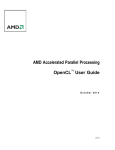
LLVM, Low Level Virtual Machine, is a compiler framework that once started as
a research project at the University of Illinois [20]. It has since then grown to
become a full fledged compiler framework used in industry applications and now
includes front-ends for several languages and back-ends for several architectures
[19]. The version of LLVM used in this project is LLVM 3.0.
LLVM front-ends parse and compile source code into LLVM’s internal representation [19]. LLVM then does target independent optimizations on this internal
form [19]. It is then the task of the LLVM back-end to lower this internal representation into machine code [19].
2.3 LLVM
17
Figure 2.13. LLVM compiler framework overview
2.3.1
Clang
Clang is the LLVM native C/C++ and Objective C front-end. The front-end is
responsible for parsing the source code and generating LLVM internal representation for later stages in the compilation process. The version of Clang used in this
project is Clang 3.0.
2.3.2
LLVM passes
LLVM provides interfaces for inserting code analysis and transformation passes
into the compilation pipeline. The different interfaces decide on which level the
pass will work, this includes modules (file level), functions, loops, basic blocks and
more.
2.3.3
Back-ends
LLVM has several back-ends for generating machine code for different architectures
and for generating C or C++ code. LLVM provides interfaces that need to be
implemented and registered with the compiler during runtime for lowering LLVM
internal representation to target machine code.
18
Background
2.3.4
LLVM internal representation
The LLVM internal representation is a complete strongly typed programming language with a [19]. Figure 2.15 shows a function taking two integer arguments and
sums them to a global variable sum. The code was generated from the C code in
Figure 2.14.
1
2
3
4
5
6
i n t sum = 0 ;
void f u n c ( i n t x , i n t y )
{
sum = x + y ;
}
Figure 2.14. Baseline language example.
1
2
3
4
5
6
7
8
9
10
11
12
13
14
@sum = common g l o b a l i 3 2 0 , a l i g n 4
d e f i n e v o i d @func ( i 3 2 %x , i 3 2 %y ) nounwind uw t ab l e {
entry :
%x . addr = a l l o c a i 3 2 , a l i g n 4
%y . addr = a l l o c a i 3 2 , a l i g n 4
s t o r e i 3 2 %x , i 3 2 ∗ %x . addr , a l i g n 4
s t o r e i 3 2 %y , i 3 2 ∗ %y . addr , a l i g n 4
%0 = l o a d i 3 2 ∗ %x . addr , a l i g n 4
%1 = l o a d i 3 2 ∗ %y . addr , a l i g n 4
%add = add nsw i 3 2 %0, %1
s t o r e i 3 2 %add , i 3 2 ∗ @sum , a l i g n 4
r e t void
}
Figure 2.15. LLVM IR language.
The program in figure 2.15 was compiled with ’-O0’ so the generated code lacks
most optimizations. The program works as follows.
• Line 1: Declare a global variable @sum which is of type 32-bit integer.
• Line 3: Declare the function @func which takes two 32-bit integers as arguments and returns nothing, void.
• Lines 5-6: Allocate space on the stack for two 32-bit integer variables.
• Lines 7-8: Store the function arguments to the stack.
• Lines 9-10: Load the arguments into registers %1 and %2.
• Line 11: Add %1 and %2 into register %add.
2.3 LLVM
19
• Line 12: Store %add to global variable @sum.
• Line 13: Return nothing.
LLVM was chosen for this project because it is open source, has a large developer community and is supported by the industry [19]. This guarantees that the
LLVM project will continue even if individual developers leave the project.
LLVM also has a very modular design and has back-ends for many architectures. It has also earlier been re-targeted to a VLIW architecture [1]. This shows
us that it is not impossible to re-target LLVM to a new VLIW-like architecture.
2.3.5
TableGen
TableGen is a language used to describe records holding domain specific information. In this case information about CPU features, registers, instructions and
calling conventions. TableGen descriptions are used to generate C++ code that
can be used in our back-end later. Expansion of TableGen into C++ is done
during compilation of the back-end.
TableGen supports inheritance so common information shared between all instances of the record we are trying to implement can be stored in the base class of
that record type to reduce work. Figure 2.16 shows how registers in the REPLICA
back-end have been implemented using inheritance. The TableGen definitions look
very much like C++ templates.
• Line 1: Defines registers in the REPLICA back-end.
• Line 8: Defines the specialization integer registers from REPLICAReg.
• Line 12: Defines the integer register R0 from Ri.
1
2
3
4
5
6
7
8
9
10
11
12
c l a s s REPLICAReg<s t r i n g n> : R e g i s t e r <n> {
f i e l d b i t s <6> Num;
l e t Namespace = "RP " ;
}
// R e g i s t e r s a r e i d e n t i f i e d with 6− b i t ID numbers .
// Ri − 32− b i t i n t e g e r r e g i s t e r s
c l a s s Ri<b i t s <6> num , s t r i n g n> : REPLICAReg<n> {
l e t Num = num ;
}
d e f R0
: Ri< 0 , " R0" > , DwarfRegNum <[0] >;
Figure 2.16. REPLICA registers defined in TableGen.
Multiclass is a special TableGen feature; it lets us define a common name
to inherit from that contains several classes. This is heavily used when defining
20
Background
instructions because, for example, most ALU instructions have several formats but
only differ in the instruction name being used.
Note that we decided to encode several REPLICA sub-instructions in so called
super-instructions so that it became easier to map REPLICA sub-instructions to
LLVM IR.
1
2
3
4
5
6
7
8
9
10
11
12
13
14
15
16
17
18
19
m u l t i c l a s s Instr_ALU<s t r i n g OpcStr , SDNode OpNode> {
l e t Uses = [ A0 ] , D e f s = [ A0 ] , TSFlags = 0 x1000 i n {
d e f r r : InstRP <( o u t s I n t R e g s : $ d s t ) ,
( i n s IntRegs : $src1 , IntRegs : $src2 ) ,
! s t r c o n c a t ( OpcStr , " 0 $ s r c 1 , $ s r c 2 WB$dst A0 " ) ,
[ ( s e t I n t R e g s : $dst ,
( OpNode I n t R e g s : $ s r c 1 , I n t R e g s : $ s r c 2 ) ) ] > ;
l e t Uses = [ O0 ] , D e f s = [ O0 ] i n {
d e f r i : InstRP <( o u t s I n t R e g s : $ d s t ) ,
( i n s I n t R e g s : $ s r c 1 , i32imm : $ v a l ) ,
! s t r c o n c a t ( "OP0 $ v a l " ,
! s t r c o n c a t ( OpcStr , " 0 $ s r c 1 , O0 WB$dst A0 " ) ) ,
[ ( s e t I n t R e g s : $dst ,
( OpNode I n t R e g s : $ s r c 1 , imm : $ v a l ) ) ] > ;
}
}
}
defm ADD : Instr_ALU <"ADD" , add >;
Figure 2.17. REPLICA super-instructions defined in TableGen.
Figure 2.17 defines a multiclass Instr_ALU which contains two variants of an
ALU super-instruction: An ALU operation between two registers and an ALU
operation between a register and an immediate. To use this multiclass for an
add instruction in these two variants we use defm on line 19. This will create an
ADDrr and an ADDri, which follows the definitions on line 3 and line 9 with OpcStr
replaced with ADD and OpNode replaced with add.
As can be seen in Figure 2.17 each TableGen instruction definition consists
of several REPLICA sub-instructions, so called super-instructions. For example
ADDri contains three REPLICA sub-instructions, OP, ADD and WB. We decided
to use this implementation style so that we could let LLVMs code generation
algorithm select and order instructions without any modifications.
2.4
Alternative Compilers
If it for some reason would not be possible to use LLVM for this project we have
looked into some other compilers that could be used instead. The compilers we
have studied are Open64, Trimaran, ROSE, COINS, fcc, VEX and GCC.
2.4 Alternative Compilers
21
Open64
SGI released their MIPSpro compiler under an open source license in 2000 under
the name Pro64. This later became the Open64 compiler. The compiler supports
C/C++, Fortran95 and can generate code for many architectures such as IA-64
etc.[22].
According to Ming Lin et al. [22] re-targeting the Open64 compiler to a new
architecture is a hard and error-prone task as no automated tools for re-targeting
exist.
Trimaran
Trimaran is a compiler made for research in computer architecture and compiler
optimizations [8]. Trimaran can target a wide range of architectures such as VLIW
processors [8].
Trimarans modular nature should make it relatively easy to add support for a
new architecture. But as a research compiler framework it has limited user group.
ROSE
ROSE is a source-to-source compiler infrastructure that can read and write source
code in multiple languages [7]. ROSE is primarily for software analysis and transformation tools and code generation tools [7].
COINS
COINS (a COmpiler INfraStructure), is a research project aiming to create a base
for constructing other compilers [26]. COINS is written in Java and has two forms
of intermediate representation HIR (High-level Intermediate Representation) and
LIR (Low-level Intermediate Representation) [26].
fcc
The Fork95 compiler for SB-PRAM. SB-PRAM is a realization of PRAM built at
Saarbrücken University [17]. SB-PRAM has up to 4096 RISC-style processors and
up to 2 GB of shared memory [17]. The shared memory is accessible in one CPU
cycle by any processor.
Fork95 is based on ANSI C with additional constructs for creating parallel
processes, dividing groups of processors into subgroups, managing shared and
private address subspaces [17].
REPLICA is also a PRAM realization so fcc might be an alternative to LLVM.
VEX
VEX, short for “VLIW example”, is an example architecture that accompanies the
book “Embedded computing - a VLIW approach to architecture, compilers and
tools” by Joseph A. Fisher et al. [11]. The architecture and compiler is based on
HPs/STs Lx/ST200 family of VLIW processors and their compiler [11].
22
Background
The VEX C compiler has some support for dynamic reconfiguration [11]. Available resources(ALUs, issue slots, memory-ports and multipliers), issue-use delay(the time between instructions issue and output ready) and the number of
registers [11].
GCC
GCC, short for GNU Compiler Collection, is a collection of compilers and tools for
several languages such as C, C++, Objective-C, Objective-C++, Java, Fortran,
Ada and Go [3]. GCC is a part of the GNU project and licensed under the
GNU General Public License [3]. GCC uses an internal representation called
RTL (Register Transfer Language) [2]. The process is similar to LLVM, a source
program is parsed and transformed into a parse tree [2]. The parse tree is then
matched against instruction patterns [2]. The instruction patterns is then matched
against RTL templates to generate assembler [2].
We believe that writing a back-end for LLVM will probably be simpler than
writing a back-end for GCC.
2.5
Related work
EPICOpt2 is a project at the Vienna University of Technology that aims to develop
new algorithms that try to maintain the advantages of integer linear programming
code generation techniques while still being computationally feasible for real world
programs [1]. An LLVM back-end for Texas Instrument’s TMS320C64X family of
VLIW processors is being developed for the EPICOpt project [4]. TMS320C6455,
is currently the fastest processor in the TMS320C64X family. It has eight functional units and can execute up to eight 32 bit instructions per clock cycle [27].
There is also an LLVM back-end for Intel Itanium (IA-64) [5], but the author
has not been able to find more information about it than an almost empty wiki
[6] and a project page at Sourceforge with source code [5].
Because LLVMs IR format does not match that well with REPLICAs instruction format a compromise was to let the back-end generate code for a default
REPLICA configuration and later reschedule and optimize the generated code for
the REPLICA implementation at hand. Basic block scheduling (i.e. scheduling of
instructions within basic blocks) seemed like a good starting point. There is a lot
of research available on basic block scheduling.
Kessler et al. show in [18] a dynamic programming based algorithm which
produces optimal or highly optimized code. Leupers et al. give an integer linear
programming based algorithm in [21] which produces high quality optimized code.
Lorenz et al. show an genetic algorithm for code generation in [23]. Eriksson et al.
show in [10] both an algorithm based on a genetic algorithm which produces code
one or two clock-cycles from optimum (in the cases where an optimal schedule is
known) and a integer linear programming based algorithm.
2 Optimal
Code Generation for Explicitly Parallel Processors [1]
Chapter 3
Implementation
Our LLVM back-end converts LLVM internal representation to MBTAC assembler
for a minimal REPLICA configuration. We also have an optimization pass that
tries to restructure our generated assembler so that we use available functional
units more effectively. The LLVM framework provides generic algorithms for code
generation, that when necessary use parts of the target machine’s back-end.
To generate code for REPLICA we need to describe it to LLVM, information
such as instructions, registers, calling conventions and how LLVM IR is to be lowered to MBTAC assembler is needed. This is done with a combination of C++ and
TableGen (see section 2.3.5, LLVMs target description language. Almost all source
code for our back-end is located in <llvm-source-dir>/lib/Target/REPLICA. Some
modifications outside of this directory were needed i.e. we needed to add our new
back-end to <llvm-source-dir>/include/ADT/Triple.h and
<llvm-source-dir>/lib/Support/Triple.cpp so that it becomes a selectable target.
When adding a new back-end to LLVM we also need to register it at runtime
so that LLVM knows it exists. Most classes in our LLVM back-end are accessed
through the REPLICATargetMachine class so that has to be registered with the
LLVM target registry. We also need some output method from the back-end, in
our case we only have the assembler printer so that also needs to be registered with
LLVM and this is done separately from the target machine registry. See Figure
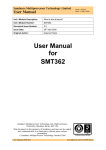
3.1 for an architectural overview of the back-end.
We also modified the Clang front-end so that it knows about REPLICA’s
register names and available in-line assembler constraints.
23
24
Implementation
Figure 3.1. Architectural overview of the REPLICA back-end.
3.1 Code generation
3.1
25
Code generation
The main objective of this project was to generate assembler code for the REPLICA
architecture. LLVM provides a target independent framework for code generation
where the target architectures only have to add handling and descriptions of target
specific features.
The code generation process starts with the program in LLVM internal representation format and ends with the finished assembler code being printed to a file.
During this process the code passes through many stages where the output of each
stage is one step closer to the final assembler code. The following sections detail
the code generation process and the steps needed to transform LLVM internal
representation to MBTAC assembler.
3.1.1
Instruction selection
LLVM uses a selection DAG, Directed Acyclic Graph, based instructions selector
to translate LLVM internal representation to target specific code. Parts used by
the instruction selector are generated from TableGen files. Parts that need custom
handling are written in C++.
A DAG based instruction selector basically keeps the programs internal representation in a tree structure and then tries to match subtrees of this to the
TableGen defined instructions. If a match is found the subtree is converted to the
target specific node of the matched instruction.
SelectionDAG construction
This pass constructs a DAG from the LLVM internal representation version of the
program we are compiling. Most of this is done by the built in TableGen definitions
of LLVM internal representation but the DAG constructor needs custom handling
for some constructs, mainly function calls and returns.
This step uses the REPLICATargetLowering class to find out what to do with
function calls. REPLICATargetLowering is accessible through the main class of
the REPLICA back-end, REPLICATargetMachine, see figure 3.1.
SelectionDAG legalize types
LLVM internal representation is a very generalized machine so data types used in
LLVM internal representation may not be supported on the target machine. The
sub-target class provides LLVM with a TargetData description of what types and
sizes are supported on the target architecture.
The code generation process uses the target data layout to convert the instructions in the DAG to only use data types supported by our version of REPLICA.
SelectionDAG legalize
This pass converts the DAG to only use instructions supported by the target architecture. This pass uses REPLICATargetLowering to determine if an instruction
26
Implementation
is legal or need to be expanded, promoted or needs custom handling.
• Expand: LLVM tries to generate simpler instructions that would produce
the same result as the expanded instruction.
• Promote: The instruction is promoted to a more general instruction.
• Custom: This instruction is too complex for TableGen. Instead call a function in REPLICATargetLowering that will take care it.
SelectionDAG optimization
The focus of the earlier passes is to generate legal code. This pass cleans up
the code from the earlier passes. It also performs some optimizations on the
code generated by earlier passes. An important optimization that is performed
by LLVM at this stage is optimization of the automatically inserted sign-/zeroextension code.
SelectionDAG instruction selection
This pass uses our instruction definitions generated from TableGen to select REPLICA
instructions that match the LLVM internal representation instructions already in
the DAG. LLVM uses pattern matching on subtrees of the selection DAG to pick
which REPLICA instructions to use.
The instruction selection pass uses REPLICAInstrInfo whose base class was
generated from TableGen. The output of the instruction selection pass is a DAG
with only target specific nodes.
SelectionDAG scheduling and formation
In the earlier passes the order between instructions has not been specified only
the dependencies between nodes in the DAG. The Scheduling and formation pass
in LLVM assigns order to all instructions and transforms the DAG to a list of
instructions.
The DAG is destroyed after scheduling and formation is done and the list of
machine instructions is sent to the next pass.
3.1.2
SSA based optimization
This pass allows for target specific optimization before register allocation. We do
not use this pass because we will insert more code in the prolog and epilog of
functions and we would like to optimize that inserted code as well.
3.1.3
Register allocation
Until this pass instructions have used virtual registers. Now it is time to assign
physical registers to these virtual registers. For this LLVM uses a target independent register allocation algorithm that uses information about REPLICA registers
3.2 Target machine description
27
that we defined in TableGen, see the REPLICARegisterInfo class in figure 3.1.
There are several register allocation algorithms available to the developer to choose
from. By default the register allocator is chosen according to optimization level
but this can be changed with command-line options to the LLVM compiler(llc).
3.1.4
Prolog/Epilog code insertion
The prolog/epilog code insertion pass handles calculating a new stack pointer and
restoring the old stack pointer when leaving the function. We also must save and
restore registers that are used by the callee and the called function. This is done
in C++ by the REPLICAFrameLowering class, see figure 3.1.
3.1.5
Late machine code optimizations
The late machine code optimization pass is used to perform target specific optimizations on the finished machine code before outputting it. This is where we
perform our optimizations for instruction level parallelism. We also implemented
a debug pass here that would print all machine instructions in a tree like structure
to ease debugging.
3.1.6
Code emission
The last pass in the code generation process is code emission. This is were the
generated machine code is outputted to file, in our case that is assembler code
printing. Code emission is registered separately from the back-end for LLVM, see
REPLICAAsmPrinter and REPLICAMCAsmStreamer in figure 3.1 The generated
machine instructions are printed to a .s file.
3.2
Target machine description
The REPLICATargetMachine class, see figure 3.1, is the main component of our
REPLICA back-end implementation. It implements the LLVMTargetMachine interface that LLVM uses to access classes holding target specific information such
as instructions, registers, sub-targets, target lowering, target data layout and selection DAG information.
• REPLICAInstrInfo: Instructions are described in TableGen with some additional C++ code to handle register to register copy DAG nodes. This
is handled by the REPLICAInstrInfo class which is accessed through the
REPLICATargetMachine class.
• REPLICARegisterInfo: LLVM needs to know what registers we have available and what data types they support. This information is described in
TableGen and in the REPLICARegisterInfo class that is accessed through
the REPLICATargetMachine class.
28
Implementation
• REPLICAFrameLowering: Takes care of prolog/epilog code insertion, saving, and restoring registers at function calls. This is handled by the REPLICAFrameLowering class that is accessed through the REPLICATargetMachine class.
• Data layout: Supported data types are implemented in the sub-targets because this could vary between sub-targets. For the moment we only have one
generic sub-target. Data layout is a string describing supported data types
on the REPLICA architecture, explained in detail in the sub-target section.
• REPLICATargetLowering: Describes how LLVM internal representation instructions should be lowered and if instructions need custom handling. This
is handled by the REPLICATargetLowering class which is accessed through
the REPLICATargetMachine class.
• Sub-targets: Additional information about sub-targets. In our case we only
have one implemented sub-target: The generic 32 bit REPLICA machine
with no additional features.
The Target also needs to be registered with the TargetRegistry so that LLVM
is able to find and use our target during runtime. To make our REPLICA target
available to LLVM we need to first register our target name so that it becomes
selectable at compile time. The two code fragments in figure 3.2 and 3.3 are needed
to register our REPLICA target machine and the generic REPLICA sub-target.
1
2
R e g i s t e r T a r g e t <T r i p l e : : r e p l i c a >
X( TheREPLICATarget , " r e p l i c a " , "REPLICA" ) ;
Figure 3.2. Register the REPLICA target with LLVM’s TargetRegistry.
1
2
R e g i s t e r T a r g e t M a c h i n e <REPLICA32TargetMachine>
X( TheREPLICATarget ) ;
Figure 3.3. Register the generic sub-target with the TargetRegistry.
We also need to add our assembler printer as an output method and we have
also modified the raw printing of assembler instructions to handle the possibility
of chaining assembler instructions. The two code fragments in Figure 3.4 and 3.5
registers our assembler printer and assembler streamer.
3.2 Target machine description
1
29
R e g i s t e r A s m P r i n t e r <REPLICAAsmPrinter> X( TheREPLICATarget ) ;
Figure 3.4. Register the assembler printer with LLVM’s TargetRegistry.
1
2
T a r g e t R e g i s t r y : : R e g i s t e r A s m S t r e a m e r ( TheREPLICATarget ,
createREPLICAAsmStreamer ) ;
Figure 3.5. Register the assembler streamer used by our assembler printer.
3.2.1
Sub-targets
There is currently only one sub-target for the REPLICA target machine, which
is the default 32 bit REPLICA machine. This sub-targets define a machine with
support for 32 bit addresses, 32, 16 and 8 bit integers and no floating point support.
The data layout definition is just a string returned by the sub-target, see figure
3.6.
1
2
3
4
s t d : : s t r i n g getDataLayout ( ) const
{
return s t d : : s t r i n g ( "E−p : 3 2 : 3 2 : 3 2 − i : 3 2 : 3 2 : 3 2 − i : 1 6 : 1 6 : 1 6 − i : 8 : 8 : 8 " ) ;
}
Figure 3.6. The sub-targets data layout definition.
The E in the data layout string tells LLVM that this architecture is big-endian.
The p is pointer information, the first value being pointer size, the next two values
are ABI1 and preferred alignment. We also have support for 32-, 16- and 8-bit
integers with 32-, 16- and 8-bit ABI and alignments.
Source code for this part can be found in the following files.
• REPLICA.td
• REPLICATargetMachine.h
• REPLICATargetMachine.cpp
• REPLICASubtarget.h
• REPLICASubtarget.cpp
1 Application
Binary Interface
30
Implementation
3.3
Registers
Register set and register classes are described using LLVM’s TableGen language
which is transformed to C++ during compilation of the compiler. In our version
of the processor all registers are 32-bit integer registers but there are still some
differences between them. Some are associated with specific functional units. Currently there are four register classes: IntRegs, ALURegs, MEMRegs and OPRegs,
see Table 3.1.
Table 3.1. Register classes for REPLICA.
Register class
IntRegs
ALURegs
MEMRegs
OPRegs
Description
General purpose 32-bit integer registers.
Registers holding results of ALU operations. For example the result of an add instruction in ALU 0 will
be placed in ALU register 0.
Registers holding results from memory operations.
For example the result of a load in memory unit 0
will be placed in memory register 0.
OPRegs can be used to insert constants in assembler
code. These are volatile registers as they don’t keep
their value between clock cycles.
Super instructions that are generated before our ILP optimization do only use
the general purpose integer registers and implicitly define and/or use registers from
other register classes. This is later adressed by our instruction splitter.
The REPLICARegisterInfo class, see Figure 3.1, implements functions for handling reserved registers, callee saved registers, handling of pseudo instructions generated during function call lowering and frame index handling.
• Callee saved registers is a list of registers used by LLVM when emitting
prolog/epilog code. If a register in this list is used inside a function we need
to generate code for saving this register in the prolog of the function. We also
need to generate code for restoring this register in the epilog of the function.
• Removal of pseudo instructions are also done by REPLICARegisterInfo. The
call frame pseudo instructions (callseq_start and callseq_end) were used to
group instructions belonging to a function call together so that they are
handled as a single unit by later optimization passes. These pseudo instructions also contain the size of arguments put on the stack; this information
would be useful if we were to implement handling of variable sized arguments. For now we only remove these instructions. This is implemented in
eliminateCallFramePseudoInstructions.
• During compilation instructions using data in a stack slot access that stack
slot with an abstract offset (0, -1, -2, etc.) so before emitting assembler
3.3 Registers
31
we need to replace these abstract offsets with the real offset. For this the
eliminateFrameIndex function is used.
Reserved registers is a vector of IntRegs that are used for special purposes, for
example the register holding the stack pointer is a special purpose register.
Table 3.2. Special purpose registers, note n is the total number of registers. The number
inside the parentheses is the number used in our version of the processor.
Register
R0
R29
R30
R31
Rn-1 (32)
Rn(33)
Back-end internal name
RP::R0
RP::SP
RP::TID
RP::RA
RP::TPA
RP::SR
Description
A constant zero.
Stack pointer.
Thread ID.
Return address.
Thread private address space start.
Status register.
Table 3.2 gives a short list of the registers currently in the special purpose
register list.
• R29, the stack pointer, is used for accessing data stored on the stack, for
example local variables, function arguments or spilled registers.
• R30 holds the current thread ID. The ID of the current thread can also
be found in the built-in variable _thread_id, see Section 2.2.1 for more
information about the baseline language and built-in variables.
• R31 holds the return address of the previously executed jump and link instruction (“JMPL”). The return address register is used when returning from
a function call.
• The special purpose register holding the starting address of the thread private memory space varies with configuration and is used by load and store
instructions when accessing data in a thread’s private memory space.
• The status register holds the result of the latest compare instruction and is
used by branch instructions.
Source code for this part can be found in the following files.
• REPLICARegisterInfo.td
• REPLICARegisterInfo.h
• REPLICARegisterInfo.cpp
• REPLICAFrameLowering.h
• REPLICAFrameLowering.cpp
32
Implementation
3.4
Instructions
The REPLICA instructions are described using TableGen. The description includes output registers, input registers, assembler string and the DAG pattern
that the instruction should be matched against. If several DAG patterns can be
used for the same instruction then each pattern would need a seperate TableGen
definition of the instruction.
Because of the strange instruction format for this architecture we decided to
encode several instructions into super-instructions that would be matched against
DAG patterns. We then later split these super-instructions into the sub-instructions
they encode. With this method we avoid much of the custom lowering we otherwise
would have needed to correctly schedule all sub-instructions. Some instructions
need custom lowering; for example function calls, returns and global address calculation.
Function calls are described in the next section. Global addresses need custom
handling because of the architecture’s memory organization. A private variable
will be located in the thread private memory space, a shared variable will be
located in the shared memory space and a text label will be located in the program
memory space. No offset is needed for the shared memory and program memory,
here we can use the label directly. If the variable is thread private then we must
offset the location with the start of private address space which is conveniently
stored in a register.
Source code for this part can be found in the following files.
• REPLICAInstrInfo.td
• REPLICAInstrInfo.h
• REPLICAInstrInfo.cpp
• REPLICAISelLowering.h
• REPLICAISelLowering.cpp
• REPLICAISelectionDAGInfo.h
• REPLICAISelectionDAGInfo.cpp
3.4.1
Calling conventions
The basic calling convention information is defined with TableGen in REPLICACallingConvention.td. That file defines how many registers we have to pass arguments in and
their types; it also defines what should happen with arguments that do not match the
type of the registers used and what should be done if there are more arguments than
registers.
We decided to use a calling convention where the first argument to a function is put
in register R2 and any subsequent arguments are pushed to the stack. Arguments on the
stack are put in slots with a size of 4 bytes that are 4 byte aligned. The return value of
a function is put in register R1.
There are three methods that are responsible for handling calls and return values.
LowerCall, LowerFormalArguments and LowerReturn.
3.5 Assembly printer
33
• LowerCall checks the number of arguments and allocates room on the stack if
needed. LowerCall then creates instructions for moving arguments to their correct place and, when all the arguments are in place, generates a call instruction.
LowerCall is also responsible for taking care of the return value if any.
• LowerFormalArguments checks the number of arguments and generates instructions for moving arguments from the stack to registers.
• LowerReturn moves the return value into register R1 and then generates a return
instruction.
Source code for this part can be found in the following files.
• REPLICACallingConv.td
• REPLICAISelLowering.h
• REPLICAISelLowering.cpp
3.5
Assembly printer
The printing of assembler code is split into three classes, one low level printing, one for
handling machine instructions and one for holding settings.
• REPLICAAsmPrinter: Splits a machine instruction into its operands and calls the
function needed to print the operand. REPLICAAsmPrinter is also responsible for
printing assembler directives around functions.
• REPLICAMCAsmStreamer: Does the raw printing to file and is also responsible
for printing assembler directives for variables.
• REPLICAMCAsmInfo: Defines directive texts and features available for the assembler printer.
Because MBTAC assembler is different from how assembler languages are structured
in general we decided to implement a custom assembler streamer i.e. the class responsible
for the low level writing of assembler to file. The most important change is the handling
for printing chained sub-instructions. To encode that the current sub-instruction being
printed has more chained subsequent sub-instructions we added an ending ’!’ to the
assembler string, See Figure 3.7. An empty delimiter instruction is used to end the
chain, see line 4 in Figure 3.7.
1
2
3
4
// Branch t o Ox i f IC not e q u a l s z e r o
d e f R_BNEZ : InstRP <( o u t s ) , ( i n s OPRegs : $ b r d s t ) ,
"BNEZ $ b r d s t ! " , [ ] > ;
d e f d e l i m i t e r : Pseudo <( o u t s ) , ( i n s ) , " \ n " , [ ] > ;
Figure 3.7. The assembler string on line 3 ends with a ’!’ so that the assembler streamer
does not automatically insert a newline after the sub-instruction.
The assembler printer is also currently printing the initialization function “_ProgramStart” that initializes built-in variables. This function ought to be moved into the
runtime library for future releases of the REPLICA back-end.
Source code for this part can be found in the following files.
• REPLICAAsmPrinter.cpp
34
Implementation
• REPLICAMCAsmStreamer.h
• REPLICAMCAsmStreamer.cpp
• REPLICAMCAsmInfo.h
• REPLICAMCAsmInfo.cpp
3.6
Clang basic target information
Because our REPLICA back-end relies on inline assembler for using the special multiprefix instructions we need to give clang, the compiler front-end, information about the
REPLICA architecture, such as:
• Available registers. To use constraints in assembler inlining we would need to define
the available register names for Clang.
• Useable constraints. Currently only register constraints, “r”.
• Built-in defines.
Assembler inlines in Clang follow the same style as gcc although our back-end is fairly
limited in the amount of available assembler constraints.
The built-in defines can be used by the programmer to check that we are compiling
for REPLICA. Thus can be useful to separate REPLICA specific code from platform
independent code. The defines are given in the list below and can be used with for
example “#ifdef”.
• __replica__
• _ARCH_REPLICA
• __replica_mbtac__
• __REPLICA_MBTAC__
Source code for this part can be found in the following file.
• <llvm-source-dir>/tools/clang/lib/Basic/Targets.cpp
Chapter 4
Optimization
To handle the configurable number of functional units we decided to implement an optimization pass that would work on the almost finished machine code. By doing this
division we can have the compiler generating code for a minimal configuration by default
and then letting the optimization pass handle rescheduling of instructions for specific
REPLICA configurations. The optimization algorithm used for rescheduling was based
on the virtual ILP algorithm in [14] by M. Forsell.
LLVM lets us insert new compiler passes for code transformation and analysis at
different stages in the compiler. We added an optimization pass at the pre-emit stage i.e.
just before instruction printing. An advantage with this approach is that all generated
code like prolog/epilog stack adjustments has already been added. A disadvantage is
that all instruction are now in list-form so we need to construct a dependence graph out
of this list with instructions and also because registers have already been assigned we
could have introduced artificial dependencies between instructions.
Because of the decision to map LLVM internal representation to REPLICA superinstructions we first need to divide these super-instructions so that the optimizer can try
to reorder them.
4.1
Instruction splitter
Before the generated code is sent to the assembler printer it passes through the instruction
splitter. The instruction splitter is a LLVM pre-emit pass where each super-instruction
is divided into the sub-instructions it encodes.
1
OP0 2
ADD0 O0 , R1
WB1 A0
Figure 4.1. Instruction splitting.
As an exampled, before instruction splitting (line 1 in figure 4.1) is seen as one
instruction by the compiler. After instruction splitting on the other hand OP0 2, ADD0
O0,R1 and WB1 A0 are seen as separate instructions.
Source code for this part can be found in the following file.
35
36
Optimization
• REPLICAInstrSplitter.cpp
4.2
Dependence DAG
A general scheduling approach is to construct a dependency graph to represent the constraints on instruction schedules i.e. in which order instructions need to be scheduled
[25]. As control flow through a basic block is always from the first instruction in the
block to the last instruction in the block with no branches in-between, the dependency
graph for a basic block always becomes a DAG (Directed Acyclic Graph) [25].
The nodes in the dependence DAG are REPLICA machine instructions and there
is an edge between two nodes N1 and N2 if N2 depends on N1 . The REPLICA backend’s implementation of a dependence DAG for pre-emit rescheduling of instructions
transforms REPLICA machine instructions in list form to a graph with dependencies.
1
2
3
4
5
6
_BB0_1
OP0 0
OP0 9
LD0 R1
SGTU R1 , R2
; %f o r . cond
; =>This I n n e r Loop Header : Depth=1
WB1 A0
ADD0 R29 , O0
WB2 O0
WB1 M0
OP0 _BB0_3
BNEZ O0
Figure 4.2. Basic block for the conditional of a for loop.
Figure 4.2 shows a basic block for the conditional check in a for loop. The instructions
in this basic block are read from the OP0 0 on line 1 to BNEZ O0 on line 3 and from this
the dependence DAG in figure 4.3 is constructed.
19 : R_OPi Reg:4<def> Imm:0
-1
20 : R_ADDro Reg:1<def> Reg:38<use> Reg:4<use><kill>
1
1
1
21 : R_WBra Reg:9<def> Reg:1<use><kill>
1
2
1
2
2
23 : R_WBrm Reg:9<def> Reg:3<use><kill>
1
1
1
2
2
1
1
1
25 : R_WBro Reg:10<def> Reg:4<use><kill>
1
2
2
24 : R_OPi Reg:4<def> Imm:9
-1
22 : R_LDr Reg:3<def> Reg:9<use><kill>
2
1
27 : R_OPi Reg:4<def> Unkown
1
2
26 : R_CSGTUrr Reg:9<use><kill> Reg:10<use><kill> Reg:2<def>
-1
1
28 : R_BNEZ Reg:4<use><kill> Reg:2<use>
Figure 4.3. Dependence DAG from the conditional check in a for loop.
Figure 4.3 is a graphical representation of the dependencies between instructions in
a basic block. The dependencies between instructions are either register dependencies or
4.3 Optimizations for instruction level parallelism
37
additional dependencies our dependence DAG construction algorithm uses the following
rules for deciding if there is a dependency or not.
1. If instruction I1 defines register r and instruction I2 uses register r then I2 depends
on I1 .
2. If instruction I1 uses register r and instruction I2 defines register r then I2 depends
on I1 .
3. If instruction I1 defines register r and instruction I2 also defines register r then I2
depends on I1 .
4. Aside from the register conflicts there is also other dependencies to look out for
when scheduling instructions. We look for the following additional dependencies
when creating our dependence DAG.
• Load/store instructions we can not know if the address that the load instruction loads from is the same as a later store instruction saves to. So if I1 is a
load instruction and I2 is a store instruction then I2 depends on I1 .
• An inline assembler DAG node is given dependencies so that it is not moved
during optimization i.e. it is dependent on all previous instructions and all
instructions following the inline assembler node is dependent on it.
• An instruction using the result of an OP instruction must be executed in the
same step as the OP instruction therefor the edge between such DAG nodes
is given the special edge weight −1.
• An instruction using the result from a writeback (WB) instruction can not be
scheduled in the same step as the writeback so the edge between such DAG
nodes is given the weight 2.
Source code for this part can be found in the following file.
• REPLICAMCDependenceDAG.cpp
4.3
Optimizations for instruction level parallelism
The REPLICA architecture has several functional units so to effectively use the hardware we need to make sure that the utilization of functional units is high. The ILP1
optimization pass tries to reschedule instructions to increase functional unit utilization.
At the same time it must also take into account the dependencies between instructions
so that we do not for example try to use a calculated result before it is calculated. Therefor the ILP optimization pass uses the dependence DAG described earlier to find which
instructions are available to schedule at the given time. The algorithm was based on M.
Forsells virtual ILP algorithm [14], this implementation is visualized in figure 4.4.
The algorithm works on basic blocks so we know that the program flow always will
enter the block at the first sub-instruction in the block and leave the block at the last subinstruction in the block. As an effect of this we also always know that the dependencies
between sub-instructions will not have any cycles so therefor the algorithm will always
terminate.
1 Instruction
Level Parallelism
38
Optimization
Figure 4.4. Flowchart over the ILP optimization algorithm.
4.3 Optimizations for instruction level parallelism
4.3.1
39
Datastructures and algorithm details
There are three important data structures in the algorithm, aside from the dependence
DAG described earlier. Note that free sub-instructions are those sub-instructions that
have all their dependencies fulfilled.
• Ready list: Tracks the free sub-instructions that our algorithm can try to schedule.
Called can_be_scheduled_now in the source code.
• Priority list: Tracks sub-instructions that use the result from an OP sub-instruction
and therefor must be inserted in the same execution step as the OP. Called
must_be_scheduled_now in the source code.
• Delay list: Tracks sub-instructions that are delayed by a WB sub-instruction. These
sub-instructions can be moved to the ready list when scheduling the next execution
step. Called can_be_scheduled_next in the source code.
• Current sub-instruction: Not a data structure but the index in the ready list where
the sub-instruction we are currently trying to schedule is.
The optimization pass is given a machine function containing several basic blocks
and the algorithm is called once for each basic block in the machine function. The basic
block is used to build a dependence DAG and in this dependence DAG the initial free
sub-instructions are found and added to the ready list. Figure 4.4 contains a flowchart
of the algorithm, the numbers on the decision boxes corresponds to the numbers in the
following list.
1. Check if all sub-instructions in the basic block have been scheduled.
• Yes, then the algorithm is finished.
• No, then we need to continue with another loop through the algorithm.
2. Are there any sub-instructions on the priority list.
• Yes, then schedule those sub-instructions. Resources for those sub-instructions
are checked by the OP sub-instruction that they depend on. We know that
a sub-instruction on the priority list is schedulable because its preconditions
and resources were checked in the previous iteration when adding the OP
sub-instruction.
• No, then continue.
3. Have we filled all functional units or are there no more sub-instructions that can
be scheduled in this execution step.
• Yes, then finalize the sub-instructions in this execution step and output them
to their new places in the basic block, output any inline assembler that now
have all their preconditions met, copy all sub-instructions on the delay list to
the ready list and reset the current sub-instruction to the first sub-instruction
on the ready list.
• No, then continue.
4. Check if the current sub-instruction can be scheduled in the current execution step.
• Yes, then schedule the current sub-instruction in this execution step and go
to step 5.
• No, then increment the current sub-instruction to the next free sub-instruction
and go to step 1.
40
Optimization
5. Was the recently scheduled sub-instruction an OP sub-instruction?
• Yes, then add the following sub-instruction that uses the result from the
OP sub-instruction to the priority list. The resources needed by the subinstruction were checked when the OP sub-instruction was scheduled. Go to
step 6.
• No, then go to step 6.
6. Get the sub-instructions freed by scheduling the current sub-instruction and add
them to the ready list or, if the current sub-instruction was a WB, to the delay list.
Go to step 1.
4.3.2
Similarities to task scheduling
The algorithm is similar to Grahams task scheduling algorithm [16]. In Grahams task
scheduling algorithm we have a system with m tasks that should be processed by n
processors [16]. There can be dependencies between tasks so if task Tj is dependent on
task Ti then Tj must be processed later than Ti [16]. Tasks are kept on a list ordered
according to dependencies so for example Ti would come before Tj on this list [16]. A
processor searches the list from beginning to end looking for a task that can be processed.
If no task was found then the processor becomes idle until another processor finishes and
new tasks becomes available [16].
If we let Grahams processors correspond to our functional units and let tasks correspond to our sub-instructions then we can compare it to our scheduling approach for
REPLICA. REPLICA has several functional units that are assigned sub-instructions by
our algorithm. Our sub-instructions are ordered so that a sub-instruction I1 must be
executed before sub-instruction I2 if I2 depends on I1 . Functional units that are not assigned any sub-instruction can be seen as idle until a sub-instruction that matches that
functional unit is found.
Grahams processors can execute any task [16] while REPLICA sub-instructions are
keyed to a specific type of functional unit. Either operator, ALU, memory unit, compare
unit, sequencer or writeback. Hence functional units may be idle even though free subinstructions are available.
MBTACs chaining capability lets dependent sub-instructions be executed in parallel
in most cases. Writebacks is an exception where the sub-instruction dependent on the
writeback needs to wait until the next execution step. Grahams tasks on the other hand
have no chaining capability so if two tasks are dependent then the second task will have
to wait until the first has been executed before it can be scheduled [16].
The tasks in Grahams list scheduling algorithm do not have the constraint that certain
tasks must be executed in parallel [16] as REPLICAs OP sub-instructions have.
4.3.3
Time complexity
In any given basic block there would always be at least one sub-instruction that can be
scheduled in the current execution step. In a worst case scenario we could have a basic
block with n sub-instructions which consists of first k independent sub-instructions, that
uses the same functional unit, and then m sub-instructions where each sub-instruction is
dependent on the previous. Figure 4.5 shows how a worst case dependence DAG might
look like.
• At the start of the algorithm the k sub-instructions and the first of the m subinstructions are added to the ready list.
4.3 Optimizations for instruction level parallelism
41
• Now the algorithm would first schedule the first of the k sub-instructions and then
search through k − 1 sub-instructions until the last sub-instruction on the ready
list which are one of the m.
• Scheduling the last sub-instruction on the ready list would complete that execution
step and add another of the m sub-instructions to ready list (inserted last).
The check to see if all sub-instructions have been scheduled loops through all subinstructions one time in each iteration of the main optimization loop. There are two
cases m ≥ k and m < k, k + m = n.
• m ≥ k:
– We would have to iterate through k + 1 sub-instructions to schedule the first
execution step.
– For scheduling the second execution step we would have to iterate through k
sub-instructions.
– The sum would look something like: (k +1)+k +(k −1)+...+2+1+1+...+1.
The last part where the ready list only have length 1 is for scheduling the
remainder of the m sub-instructions.
+ m which is
– Calculating this as an arithmetic series we get (k + 1) ∗ k+2
2
O(k2 + m). Introducing the check to see if all sub-instructions have been
scheduled we get O(n(k2 + m)). Assuming that k > 0 and m > 0.
• m < k:
– Again we would have to iterate through k + 1 sub-instructions to schedule
the first execution step.
– At step m all the m sub-instructions have been scheduled so there is k − m
sub-instructions left on the ready list.
– To schedule the remaining sub-instructions the algorithm would pick and
schedule the first sub-instruction on the ready list and then iterate through
the remaining only to find that no more sub-instructions could be scheduled
in this execution step. At step k the scheduling would be complete.
– The sum would look something like: (k + 1) + k + (k − 1) + ... + 1.
2
– Calculating this as an arithmetic series we get (k+1)(k+2)
= k +3k+2
which is
2
2
2
O(k ). Introducing the check to see if all sub-instructions have been scheduled
we get O(n(k2 )). Assuming that k > 0 and m > 0.
The worst case time is obtained with k = m = n2 and therefor is O(n3 ).
In the best case we would be given a basic block such that the first sub-instruction
on the ready list can be scheduled in each iteration of the algorithm and there is only
one sub-instruction on the ready list in each iteration. In such a case we would only have
to go through the loop n times. Multiply that with the finish check and we get that the
best case time is Θ(n2 ).
The check to see if we have scheduled all sub-instructions is very inefficient. The
check can be done in constant time thereby bringing the worst case time complexity
down to O(n2 ) and the best case time down to Θ(n).
42
Optimization
Figure 4.5. Example of a worst case dependence DAG. Instructions of type A use
functional unit A and instructions of type B use functional unit B.
4.3.4
Practical example
As an example the code in figure 4.6 can be compressed, using the ILP optimization algorithm, to the assembler code in figure 4.7, assuming the target REPLICA configuration
has one ALU, one memory unit and two operator slots. We gained two execution steps
(lines of assembler code) with this optimization.
1
2
3
4
5
6
7
8
9
OP0 28
LD0 R1
OP0 20
LD0 R2
ADD0 R2 , R1
OP0 12
ST0 R1 , R2
OP0 0
SLT R1 , R2
ADD0 R29 , O0
WB1 M0
ADD0 R29 , O0
WB2 M0
WB1 A0
ADD0 R29 , O0
WB2 O0
OP0 _BB1_14
WB1 A0
WB2 A0
WB2 A0
BNEZ O0
Figure 4.6. Unoptimized MBTAC assembler.
1
2
3
4
5
6
7
OP0 28
OP0 20
LD0 R2
ADD0 R2 , R1
OP0 12
OP0 0
SLT R1 , R2
ADD0 R29 , O0
ADD0 R29 , O0
WB2 M0
WB1 A0
ADD0 R29 , O0
ST0 R1 , R2
OP0 _BB1_14
WB1 A0
LD0 R1
WB1 M0
WB2 A0
WB2 A0
WB2 O0
BNEZ O0
Figure 4.7. Optimized MBTAC assembler.
4.3 Optimizations for instruction level parallelism
Source code for this part can be found in the following file.
• REPLICAVirtualILP.cpp
43
Chapter 5
Evaluation
We created a number of benchmark programs to test our backed and also to see how
effective our optimization approach is. All of these programs were compiled with the
makefile in appendix C with ILP optimizations both on and off. We have to use inline
assembler in some parts of our benchmark programs because that is the only way to use
multi-prefix instructions. To get away from the use of inline assembler we would have to
add internal representation nodes that matches to these instructions.
The compiler was running on Ubuntu Linux 11.10 and the simulator was running
on Mac OS X 10.6 for all benchmarks. Source code for the benchmarks is located in
appendix C. Note that there is no sequential case for these benchmarks, the smallest
configuration used in the benchmarks has 4 processors with 512 threads each.
5.1
Parallel max/min value
The parallel max/min benchmark locates the maximum and minimum value in an array
consisting of 32768 unsigned integers. This program uses the MMAXU and MMINU multiprefix instructions so that several threads can work on the same data simultaneously.
Results
The results from the Parallel max/min value benchmark shows a small speedup both
using the ILP optimization algorithm from chapter 4 and from adding more threads. The
optimized version of the benchmark is roughly 21.8% faster than the unoptimized version
on the 4 processor configuration, on the 16 processor configuration the optimized version
is 16.9% faster than the unoptimized program and on the 64 processor configuration the
optimized program is only 11.7% faster than the unoptimized. Table 5.1 contains the
number of execution steps for running the whole program and the total number of clock
cycles.
45
46
Evaluation
Table 5.1. Running time for the parallel max/min example.
Configuration
PRAM-T5-4-512+
PRAM-T5-16-512+
PRAM-T5-64-512+
Unoptimized
Steps Cycles
480 245760
180
92160
105
53760
Optimized
Steps Cycles
394 201728
154
78848
94
48128
ILP Speedup
21.8%
16.9%
11.7%
The low gain from optimization for larger configurations of the REPLICA machine
may be because the initialization part of the program, that initializes global- and builtinvariables, is hard-coded in assembler and might have longer running time than the actual
calculation part of the program. Note that the steps is the number of assembler lines
executed and clock cycles is the total number of clock-cycles the program was running.
For a processor with 512 threads one step would equal 512 clock cycles.
Table 5.2 gives the speedup for the unoptimized and optimized version. The speedup
from running the program with configurations with more threads are quite low. But a
possible explanation for that could be because as earlier stated that the calculation part
of the program is so small compared to the initialization part.
Table 5.2. Parallel speedup for the parallel max/min example.
Configuration
PRAM-T5-4-512+
PRAM-T5-16-512+
PRAM-T5-64-512+
Unoptimized
1.0
2.67
4.57
Optimized
1.0
2.56
4.19
For a graphical comparison between the execution times of the parallel max/min
value benchmark see figure 5.1.
5.1 Parallel max/min value
Figure 5.1. The parallel max/min value benchmark cycles comparison.
47
48
5.2
Evaluation
Parallel array sum
The parallel array sum benchmark is similar to the parallel max/min value benchmark
but instead of using the MMINU and MMAXU multi-prefix instructions it uses the MMADD
instruction to add every element in an array to a summation variable.
Results
Maybe because of the similarities with the parallel min/max benchmark the gain from
optimization is not that visible because of the small size of the calculation part of the
program compared to the static part doing initialization. The optimized version is 22.3%
faster than the unoptimized version on the 4 processor configuration, 16.5% faster than
the unoptimized version on the 16 processor configuration and only 11.4% faster than
the unoptimized version on the largest 64 processor configuration.
Table 5.3 contains the executions times for the array sum benchmark. We believe
that these results have the same explanation as the parallel max/min value benchmark.
Table 5.3. Running time for the parallel sum benchmark.
Configuration
PRAM-T5-4-512+
PRAM-T5-16-512+
PRAM-T5-64-512+
Unoptimized
Steps Cycles
383 196096
155
79360
98
50176
Optimized
Steps Cycles
313 160256
133
68096
88
48128
ILP Speedup
22.3%
16.5%
11.4%
Table 5.4 contains the speedup for the unoptimized and optimized version of the
parallel array sum benchmark depending on configuration. The speedup from adding
more threads to the program shows a worse speed increase than the parallel max/min
value benchmark, probably because the summation algorithm has only one instruction
for each thread in the PRAM-T5-64-512+ configuration.
Table 5.4. Parallel speedup for the parallel sum benchmark.
Configuration
PRAM-T5-4-512+
PRAM-T5-16-512+
PRAM-T5-64-512+
Unoptimized
1.0
2.47
3.91
Optimized
1.0
2.35
3.56
For a graphical comparison of the execution times for the parallel array sum benchmark see figure 5.2.
5.2 Parallel array sum
Figure 5.2. The parallel sum benchmark cycles comparison.
Figure 5.3. The original image used in the image filter benchmarks.
49
50
5.3
Evaluation
Threshold image filter
The threshold image filter benchmark was the first larger program that we tried to
implement for REPLICA. This benchmark program needs some modifications to the
compiler generated assembler code. We need to add input and output directives manually
for the image.
An image file in the ppm image format is read with the “.FILE” directive and the
result is written to an output file with the “.SAVE” directive, see figure 5.4 for how the
directives are used in the generated assembler. The benchmark program uses the MMADD
multi-prefix instruction to quickly calculate the sum of pixel values in the image then
each thread divides that with the total number of pixels in the image to find the threshold
value.
1
2
3
4
5
6
7
8
9
10
11
.DATA
. ALIGN 1
.GLOBAL _inImage_
_inImage_ :
. FILE im4 . ppm
.DATA
. ALIGN 1
.GLOBAL _outImage_
_outImage_ :
.SAVE 921654 im4 . t h r e s h o l d . ppm
. SPACE 921654
; @inImage_
; @outImage_
Figure 5.4. Fill memory _inImage with data from a file and write memory content
_outImage to file.
Each thread now performs the threshold filter algorithm on its group of pixels and,
when the exit trap is triggered, the simulator writes the filtered image to the file in the
“.SAVE” directive. Figure 5.3 was used as input and the produced result can be seen in
figure 5.6.
Result
The speed increase from optimizing the threshold filter is much better than the earlier
benchmark programs. The optimized version is 31.5% faster than the unoptimized version
on the 4 processor configuration, 34.5% faster than the unoptimized version on the 16
processor configuration and 40% faster on the 64 processor configuration. The speed
up from optimization is better maybe because the program is larger than any of the
earlier benchmarks so the initialization part of the program does not become the largest
part of the compiled program. The different speed increases for the same program on
different configurations is very strange maybe it is something else in the configurations
that differentiates them, see section 5.5. Table 5.5 contains the contains times for the
threshold benchmark.
Table 5.6 show us that the speedup for the threshold benchmark is much larger than
for the earlier benchmarks. This is probably because the data set that the program works
on is also larger so the benefit from adding more processors and threads to the simulation
is better.
5.3 Threshold image filter
51
Table 5.5. Running time for the threshold image filter example.
Configuration
PRAM-T5-4-512+
PRAM-T5-16-512+
PRAM-T5-64-512+
Unoptimized
Steps
Cycles
12382 6340044
3924 2009597
1811
927320
Optimized
Steps
Cycles
9414 4819968
2917 1494015
1293
662527
ILP Speedup
31.5%
34.5%
40%
Table 5.6. Parallel speedup for the threshold image filter benchmark.
Configuration
PRAM-T5-4-512+
PRAM-T5-16-512+
PRAM-T5-64-512+
Unoptimized
1.0
3.15
6.84
Optimized
1.0
3.23
7.27
Figure 5.5 shows a graphical representation of the executions times for the unoptimized and optimized versions of the program.
Figure 5.5. The threshold benchmark cycles comparison.
52
Evaluation
Figure 5.6. The resulting image from the threshold benchmark.
5.4
Blur image filter
The blur image filter must load image data in the same way as the threshold image
filter.The blur image filter is the most advanced benchmark program that we built for
testing the compiler. The filter works by adding each separate color value from the pixels
in a cross around the current pixel and dividing them by the total number of pixels added
as in the equation below (an unweighted average), where pf (x, y) is a pixel in the filtered
image and po (x, y) is a pixel in the original image.
pf (x0 , y0 ) =
�x0 +s
x=x0 −s
po (x, y0 ) +
�y0 +s
y=y0 −s
po (x0 , y) − po (x0 , y0 )
T
Where s is the blurfilter size and T is the total number of pixels in the cross. Note
that the −po (x0 , y0 ) is because each pixel should be added only once to the sum. We set
the blurfilter size to 3 in our benchmark program so that there is some notable difference
between the original image and the blurred image. Figure 5.3 was used as input and the
produced result can be seen in figure 5.8.
Result
The blur image filter benchmark is the largest program that we have written and thanks
to the shared memory on the REPLICA architecture the blur filter really works well with
many threads. The speed up between the unoptimized and optimized version is 23.1%
for the 4 processor configuration, 23.6% for the 16 processor configuration and 25.4%
for the 64 processor configuration. Table 5.7 contains the execution times for the blur
benchmark program.
Table 5.8 contains the speedup for the unoptimized and optimized versions of the
benchmark and because of the shared memory in the REPLICA architecture we do not
lose any time sending data so all threads always have data to work on.
5.4 Blur image filter
53
Table 5.7. Running time for the blur image filter benchmark.
Configuration
PRAM-T5-4-512+
PRAM-T5-16-512+
PRAM-T5-64-512+
Unoptimized
Steps
Cycles
120005 61443069
31194 15971836
8962
4589052
Optimized
Steps
Cycles
97488 49913856
25237 12921852
7149
3660796
ILP Speedup
23.1%
23.6%
25.4%
Table 5.8. Parallel speedup for the blur image filter benchmark.
Configuration
PRAM-T5-4-512+
PRAM-T5-16-512+
PRAM-T5-64-512+
Unoptimized
1.0
3.85
13.39
Optimized
1.0
3.86
13.63
Figure 5.7 gives a graphical comparison of the execution times of the blur image filter
benchmark.
54
Evaluation
Figure 5.7. The blur benchmark cycles comparison.
Figure 5.8. The resulting image from the blur benchmark.
5.5 Discussion
5.5
55
Discussion
It is possible to create fast parallel algorithms for the REPLICA architecture using the
REPLICA LLVM back-end. The optimization algorithm gives varying results but for the
large benchmark programs the speed-up after optimization is quite good (roughly 10%
to 20%) for the smaller benchmark programs and very good (roughly 20% to 40%) for
the larger benchmark programs. Note that the programs have some optimization already
because LLVM chooses super-instructions when trying to find the best match for internal
representation against target machine instructions.
The blur image filter also shows an algorithm that, thanks to the shared memory,
becomes very easy to parallelize from the sequential algorithm and the speedup result
from parallelization seems very good.
The total number of elements in the datasets for the max/min value and sum benchmarks was chosen to equal the total number of threads for the largest REPLICA configuration (32768). This number should maybe be larger so that the running time of
those benchmarks becomes longer and the initialization part of the benchmarks does not
become such a large portion of the total execution time.
It is strange that speedup from ILP optimization increases when adding more processors and threads to the configuration because the program is the same independent of
configuration (it is the same file with assembler code that is loaded into the simulator).
The cause of this is hard to find, it might have something to do with the configurations
or the simulator.
Programs using the back-end are currently very primitive because there is no standard
C library support for REPLICA yet and there is a very limited amount of REPLICA
specific library definitions and code skeletons.
Other sample programs written for the compiler back-end that are not shown here
include programs for testing function calls, loop constructs and other functional testing.
In conclusion, when writing a parallel program for REPLICA, one should have in mind
that.
• The dataset for the algorithm need to be sufficiently large to get a good speed up
from optimization.
• The same applies to when adding more threads to a problem.
• Synchronization was done by hand after each loop. The synchronization function
was created using inline assembler and multi-prefix instructions.
• Synchronization is needed to guarantee that the result calculated in the loop is
finished when threads start to execute sub-instructions outside the loop.
Chapter 6
Conclusion
We have in this project created an LLVM back-end for generating code for the REPLICA
architecture, a PRAM-NUMA hybrid architecture with the interesting chaining VLIW
feature for instructions. Thanks to LLVMs TableGen repetitive tasks such as defining
available instructions and how these map to LLVMs internal representation was made
simpler.
Early in the project we decided to create so-called super-instructions to find easier
mappings between LLVMs internal representation and REPLICAs sub-instructions. The
downside of this was that we would have to split these super-instructions to make any
reordering possible because we could have unused functional units that some later subinstruction could use with some reordering. Therefor the instruction splitter was added.
With the instruction splitter implemented a dependence DAG needed to be constructed to find the dependencies between sub-instructions that could be used by the
later optimization pass to check which instructions were free to schedule. The optimization algorithm is based on Forsells virtual ILP algorithm [14] and tries to fill functional
units with any free sub-instruction (a sub-instruction is counted as free if it does not
depend on any unscheduled sub-instruction).
We also needed to modify Clang so that the compiler front-end knew about the
REPLICA architecture and what data layout and register names it had. The register
names were used in the inline assembler that was needed for using multi-prefix instructions.
An early problem we had was with stack handling in conjunction with function calls.
We needed to adjust the stack pointer in a function so that it had room for function arguments and local variables. The shared stack that REPLICA can have is not implemented
due to the difficulty with multiple threads in multiple functions all using the same stack.
It was more pressing for the author to generate working code than to implement more
specialized features.
The optimization results seem very promising: we gained a speedup ranging between
10% to 40% from simple re-ordering of sub-instructions. Using more invasive optimization
algorithms may yield even better results.
The compiler back-end is not complete but it is useable. We will in the next section
give some thoughts on possible improvements aside from the usual testing and extending
the already implemented features.
57
Chapter 7
Future work
A compiler back-end is only a part in the tool-chain for creating and compiling programs
for a computer. Other parts include front-ends, libraries, linkers and assemblers. They
are all needed to create the complete tool-chain while this back-end can be used to
compile programs for a specific REPLICA configuration. All parts of the tool-chain are
needed for this compiler to actually be useful.
• Add internal representation for multi-prefix instructions in both the Clang front
end and to LLVM so that the multi-prefix instructions can be optimized as any
other instruction.
• Improve the current optimization algorithm to find and eliminate unnecessary subinstructions and build longer chains of sub-instructions.
• Improve the optimization algorithm and add another optimization algorithm that
uses e.g. integer linear programming to find the optimal schedule for a given basic
block.
• Create build scripts that automatically generate part of the back-end for a specific
REPLICA configuration so that we can, for example, compile a new compiler that
generates code for a REPLICA configuration with 5 ALUs.
• Implement vararg support in the back-end so that the printf family of C functions
can be compiled for the back-end.
• Implement the C standard library for REPLICA and a library with useful functions
for parallelization.
• A platform independent simulator for the REPLICA architecture.
59
Appendix A
Building and using the
compiler
This appendix contains a small guide for compiling LLVM and Clang, and using it to
compile programs with the REPLICA back-end. These instructions should help you build
LLVM with Clang and the REPLICA back-end on Linux based systems.
• First make sure that you have LLVM with the REPLICA back-end and Clang with
the basic REPLICA target in <llvm-replica-src>/tools/clang.
• Create a separate build directory outside <llvm-replica-src> with: mkdir build.
• Switch to the new build directory, cd build and run cmake with cmake <llvmreplica-src>.
• Run make and wait for the compiler to compile.
• The compiler and all compiler tools should end up in build/bin when the compilation is finished.
Some command line options that are useful when compiling for REPLICA are given
below. First the option to tell Clang we are compiling for REPLICA.
• -ccc-host-triple replica-unknown-unknown, this will tell Clang to compile the
program as if we were running on REPLICA.
• -nostdinc, may be useful so that Clang does not try to include standard library
from the usual path.
To tell LLVM that we would like to generate assembler for REPLICA we use the following
command line options.
• -march=replica -mcpu=generic, our target is machine architecture REPLICA
and CPU model generic.
• -enable-replica-ilp, enables the ILP optimization pass.
• -disable-replica-instr-splitter, disables the instruction splitter. The ILP
optimization pass only works with sub-instructions so with the instruction splitter
off the ILP optimization does not work.
• -enable-replica-instr-printer, prints the machine instructions in a more readable structure which is useful when debugging the optimization pass.
61
62
Building and using the compiler
#i n c l u d e " r e p l i c a . h "
i n t main ( )
{
int a = 1 ;
int b = 2 ;
int c = a + b ;
return c ;
}
Figure A.1. Sample program to compile for REPLICA, sample.c.
Because we do not have a linker for REPLICA an LLVM IR linker, llvm-link, is
quite useful when compiling programs spread over several files. The program in figure
A.1 is compiled with the command in figure A.2.
c l a n g −S −O0 −emit−l l v m −ccc −host −t r i p l e r e p l i c a −unknown−unknown \
sample . c
Figure A.2. Use clang to convert our C program to LLVM IR.
The command in figure A.2 will produce a file sample.s containing the program from
figure A.1 translated to LLVM IR. We use the commands in figure A.3 to compile this
into LLVM bit-code, line 1, and link with other files, line 2, if needed.
llvm−a s sample . s
llmv−l i n k −o program . s . bc sample . s . bc o t h e r _ f i l e . s . bc
Figure A.3. Use llvm-as and llvm-link to convert our LLVM IR to LLVM bit-code
and to link several bit-code files into one large bit-code file.
And finally, in figure A.4, we compile the bit-code file with our program to assembler
that can be run in IPSMSimX86.
l l c −march=r e p l i c a −mcpu=g e n e r i c −asm−v e r b o s e \
−e n a b l e −r e p l i c a −i l p program . s . bc
Figure A.4. Use llc to compile our program bit-code file to MBTAC assembler.
Now our compiled program is in the file program.s.s.
Appendix B
Assembler Language
This appendix contain a list of assembler sub-instructions for the first version of the
REPLICA architecture. These sub-instruction descriptions were taken from Martti
Forsells “Baseline language, assembler and architecture” [24].
The sub-instructions are grouped according to which functional unit they belong to.
B.1
Memory unit sub-instructions
LDBn
LDBUn
LDHn
LDHUn
Xx
Xx
Xx
Xx
LDn
STBn
STHn
STn
Xx
Xx,Xy
Xx,Xy
Xx,Xy
Load byte from memory n address Xx in MU n
Load byte from memory n address Xx unsigned in MU n
Load halfword from memory n address Xx in MU n
Load halfword from memory n address Xx unsigned in MU
n
Load word from memory n address Xx unsigned in MU n
Store byte Xx to memory n address Xy in MU n
Store halfword Xx to memory n address Xy in MU n
Store word Xx to memory n address Xy in MU n
63
64
Assembler Language
MADDn
MSUBn
MANDn
MORn
MMAXn
MMAXUn
MMINn
MMINUn
Xx,Xy
Xx,Xy
Xx,Xy
Xx,Xy
Xx,Xy
Xx,Xy
Xx,Xy
Xx,Xy
Add multiple Xx to active memory Xy in MU n
Subtract multiple Xx to active memory Xy in MU n
And multiple Xx to active memory Xy in MU n
Or multiple Xx to active memory Xy in MU n
Max multiple Xx to active memory Xy in MU n
Max unsigned multiple Xx to active memory Xy in MU n
Min multiple Xx to active memory Xy in MU n
Min unsigned multiple Xx to active memory Xy in MU n
MPADDn
Xx,Xy
MPSUBn
Xx,Xy
MPANDn
Xx,Xy
MPORn
MPMAXn
Xx,Xy
Xx,Xy
MPMAXUn
Xx,Xy
MPMINn
Xx,Xy
MPMINUn
Xx,Xy
Arbitrary multiprefix add Xx to active memory Xy in MU
n
Arbitrary multiprefix subtract Xx to active memory Xy in
MU n
Arbitrary multiprefix and Xx to active memory Xy in MU
n
Arbitrary multiprefix or Xx to active memory Xy in MU n
Arbitrary multiprefix max Xx to active memory Xy in MU
n
Arbitrary multiprefix max unsigned Xx to active memory
Xy in MU n
Arbitrary multiprefix min Xx to active memory Xy in MU
n
Arbitrary multiprefix min multiple Xx to active memory
Xy in MU n
BMADDn
BMSUBn
BMANDn
BMORn
BMMAXn
BMMAXUn
Xx,Xy
Xx,Xy
Xx,Xy
Xx,Xy
Xx,Xy
Xx,Xy
BMMINn
BMMINUn
Xx,Xy
Xx,Xy
Begin add multiple Xx to active memory Xy in MU n
Begin subtract multiple Xx to active memory Xy in MU n
Begin and multiple Xx to active memory Xy in MU n
Begin or multiple Xx to active memory Xy in MU n
Begin max multiple Xx to active memory Xy in MU n
Begin max unsigned multiple Xx to active memory Xy in
MU n
Begin min multiple Xx to active memory Xy in MU n
Begin min unsigned multiple Xx to active memory Xy in
MU n
B.1 Memory unit sub-instructions
EMADDn
EMSUBn
EMANDn
EMORn
EMMAXn
EMMAXUn
Xx,Xy
Xx,Xy
Xx,Xy
Xx,Xy
Xx,Xy
Xx,Xy
EMMINn
EMMINUn
Xx,Xy
Xx,Xy
BMPADDn
Xx,Xy
BMPSUBn
Xx,Xy
BMPANDn
Xx,Xy
BMPORn
Xx,Xy
BMPMAXn
Xx,Xy
BMPMAXUn Xx,Xy
BMPMINn
Xx,Xy
BMPMINUn
Xx,Xy
65
End add multiple Xx to active memory Xy in MU n
End subtract multiple Xx to active memory Xy in MU n
End and multiple Xx to active memory Xy in MU n
End or multiple Xx to active memory Xy in MU n
End max multiple Xx to active memory Xy in MU n
End max unsigned multiple Xx to active memory Xy in
MU n
End min multiple Xx to active memory Xy in MU n
End min unsigned multiple Xx to active memory Xy in MU
n
Begin arbitrary multiprefix add Xx to active memory Xy
in MU n
Begin arbitrary multiprefix subtract Xx to active memory
Xy in MU n
Begin arbitrary multiprefix and Xx to active memory Xy
in MU n
Begin arbitrary multiprefix or Xx to active memory Xy in
MU n
Begin arbitrary multiprefix max Xx to active memory Xy
in MU n
Begin arbitrary multiprefix max unsigned Xx to active
memory Xy in MU n
Begin arbitrary multiprefix min Xx to active memory Xy
in MU n
Begin arbitrary multiprefix min multiple Xx to active memory Xy in MU n
66
Assembler Language
EMPADDn
Xx,Xy
EMPSUBn
Xx,Xy
EMPANDn
Xx,Xy
EMPORn
Xx,Xy
EMPMAXn
Xx,Xy
EMPMAXUn Xx,Xy
EMPMINn
Xx,Xy
EMPMINUn
Xx,Xy
OMPADDn
Xx,Xy
OMPSUBn
Xx,Xy
OMPANDn
Xx,Xy
OMPORn
Xx,Xy
OMPMAXn
Xx,Xy
OMPMAXUn Xx,Xy
OMPMINn
Xx,Xy
OMPMINUn
Xx,Xy
End arbitrary multiprefix add Xx to active memory Xy in
MU n
End arbitrary multiprefix subtract Xx to active memory
Xy in MU n
End arbitrary multiprefix and Xx to active memory Xy in
MU n
End arbitrary multiprefix or Xx to active memory Xy in
MU n
End arbitrary multiprefix max Xx to active memory Xy in
MU n
End arbitrary multiprefix max unsigned Xx to active memory Xy in MU n
End arbitrary multiprefix min Xx to active memory Xy in
MU n
End arbitrary multiprefix min multiple Xx to active memory Xy in MU n
End ordered multiprefix add Xx to active memory Xy in
MU n
End ordered multiprefix subtract Xx to active memory Xy
in MU n
End ordered multiprefix and Xx to active memory Xy in
MU n
End ordered multiprefix or Xx to active memory Xy in MU
n
End ordered multiprefix max Xx to active memory Xy in
MU n
End ordered multiprefix max unsigned Xx to active memory Xy in MU n
End ordered multiprefix min Xx to active memory Xy in
MU n
End ordered multiprefix min multiple Xx to active memory
Xy in MU n
B.2 Write back subinstructions
SMPADDn
SMPSUBn
Xx,Xy
Xx,Xy
SMPANDn
SMPORn
SMPMAXn
SMPMAXUn
Xx,Xy
Xx,Xy
Xx,Xy
Xx,Xy
SMPMINn
SMPMINUn
Xx,Xy
Xx,Xy
B.2
B.3
Send multiprefix add Xx to active memory Xy in MU n
Send multiprefix subtract Xx to active memory Xy in MU
n
Send multiprefix and Xx to active memory Xy in MU n
Send multiprefix or Xx to active memory Xy in MU n
Send multiprefix max Xx to active memory Xy in MU n
Send multiprefix max unsigned Xx to active memory Xy in
MU n
Send multiprefix min Xx to active memory Xy in MU n
Send multiprefix min multiple Xx to active memory Xy in
MU n
Write back subinstructions
WBn
Xx
67
Write Xx to register Rn
ALU subinstructions
ADDn
SUBn
MULn
MULUn
DIVn
DIVUn
MODn
MODUn
Xx,Xy
Xx,Xy
Xx,Xy
Xx,Xy
Xx,Xy
Xx,Xy
Xx,Xy
Xx,Xy
Add Xx to Xy in ALU n
Subtract Xx from Xy in ALU n
Multiply Xx by Xy in ALU n
Multiply Xx by Xy in ALU n unsigned
Divide Xx by Xy in ALU n
Divide Xx by Xy in ALU n unsigned
Determine Xx modulo Xy in ALU n
Determine Xx modulo Xy in ALU n unsigned
LOGDn
LOGUn
Xx
Xx
Determine rounddown(log2 (Xx)) in ALU n
Determine roundup(log2 (Xx)) in ALU n
68
Assembler Language
SELn
Xx,Xy
MAXUn
MAXn
MINUn
MINn
Xx,Xy
Xx,Xy
Xx,Xy
Xx,Xy
Select Xx or Xy according to the result of the last compare
operation (Xx if res=1, Xy if res=0)
Determine maximum of Xx and Xy in ALU n unsigned
Determine maximum of Xx and Xy in ALU n
Determine minimum of Xx and Xy in ALU n unsigned
Determine minimum of Xx and Xy in ALU n
SHRn
SHLn
SHRAn
RORn
ROLn
Xx,Xy
Xx,Xy
Xx,Xy
Xx,Xy
Xx,Xy
Shift right Xx by Xy in ALU n
Shift left Xx by Xy in ALU n
Shift right Xx by Xy in ALU n arithmetic
Rotate right Xx by Xy in ALU n
Rotate left Xx by Xy in ALU n
ANDn
ORn
XORn
ANDNn
ORNn
XNORn
CSYNCn
Xx,Xy
Xx,Xy
Xx,Xy
Xx,Xy
Xx,Xy
Xx,Xy
Xx
And of Xx and Xy in ALU n
Or of Xx and Xy in ALU n
Exclusive or of Xx and Xy in ALU n
And not of Xx and Xy in ALU n
Or not of Xx and Xy in ALU n
Exclusive nor of Xx and Xy in ALU n
Set up barrier synchronization group Xx in ALU n
SEQn
SNEn
SLTn
SLEn
SGTn
SGEn
SLTUn
SLEUn
SGTUn
SGEUn
Xx,Xy
Xx,Xy
Xx,Xy
Xx,Xy
Xx,Xy
Xx,Xy
Xx,Xy
Xx,Xy
Xx,Xy
Xx,Xy
Set
Set
Set
Set
Set
Set
Set
Set
Set
Set
result
result
result
result
result
result
result
result
result
result
-1
-1
-1
-1
-1
-1
-1
-1
-1
-1
if
if
if
if
if
if
if
if
if
if
Xx
Xx
Xx
Xx
Xx
Xx
Xx
Xx
Xx
Xx
=
�
=
<
≤
>
≥
<
≤
>
≥
Xy
Xy
Xy
Xy
Xy
Xy
Xy
Xy
Xy
Xy
else result 0 in ALU n
else result 0 in ALU n
else result 0 in ALU n
else result 0 in ALU n
else result 0 in ALU n
else result 0 in ALU n
unsigned else result 0 in
unsigned else result 0 in
unsigned else result 0 in
unsigned else result 0 in
ALU
ALU
ALU
ALU
n
n
n
n
B.4 Immediate operand input subinstructions
B.4
OPn
B.5
SEQ
SNE
SLT
SLE
SGT
SGE
SLTU
SLEU
SGTU
SGEU
B.6
BEQZ
BNEZ
JMP
JMPL
TRAP
JOIN
SPLIT
69
Immediate operand input subinstructions
d
Input value d into operand n
Compare unit subinstructions
Xx,Xy
Xx,Xy
Xx,Xy
Xx,Xy
Xx,Xy
Xx,Xy
Xx,Xy
Xx,Xy
Xx,Xy
Xx,Xy
Set
Set
Set
Set
Set
Set
Set
Set
Set
Set
IC
IC
IC
IC
IC
IC
IC
IC
IC
IC
if
if
if
if
if
if
if
if
if
if
Xx
Xx
Xx
Xx
Xx
Xx
Xx
Xx
Xx
Xx
=
�
=
<
≤
>
≥
<
≤
>
≥
Xy
Xy
Xy
Xy
Xy
Xy
Xy
Xy
Xy
Xy
unsigned
unsigned
unsigned
unsigned
Sequencer subinstructions
Ox
Ox
Xx
Xx
Xx
Xx
Xx
Branch to Ox if IC equals zero
Branch to Ox if IC not equals zero
Jump to Xx
Jump and link PC+1 to register RA
Trap
Join all threads to a NUMA bunch Xx
Split all the current NUMA bunches back to PRAM mode
threads
Appendix C
Benchmark code
C.1
Makefile
This is the makefile we used to compile the benchmark programs.
CC=b u i l d / b i n / c l a n g
LLC=b u i l d / b i n / l l c
LD=b u i l d / b i n / llvm−l i n k
LA=b u i l d / b i n / llvm−a s
CFLAGS=−I . . / i n c l u d e / −S −O0 −emit−l l v m \
−ccc −ho st −t r i p l e r e p l i c a −unknown−unknown \
−n o s t d l i b − n o d e f a u l t l i b −n o s t d i n c
LLCFLAGS=−march=r e p l i c a −mcpu=g e n e r i c − s t a t s −asm−v e r b o s e \
−e n a b l e −r e p l i c a −i l p
SOURCES=prog . c
LLVMIR=$ (SOURCES : . c =. s )
BITCODE=$ (LLVMIR : . s =. s . bc )
LINKIR=prog . s . bc
all :
$ (CC) $ (CFLAGS) $ (SOURCES)
f o r i i n $ (LLVMIR ) ; do \
$ (LA) $ $ i ; \
done
$ (LD) −o $ ( LINKIR ) $ (BITCODE)
$ (LLC) $ (LLCFLAGS) $ ( LINKIR )
70
C.2 Initialization function
C.2
71
Initialization function
This is the hardcoded assembler function used to initialize the simulator. The function
was written by Martti Forsell.
.PROC _ProgramStart
.TEXT
. ALIGN 2
.GLOBAL _ProgramStart
_ProgramStart
OP0 MEMSTART WB1 O0
OP0 MEMSIZE WB2 O0
ADD0 R1 , R2 WB3 A0
OP0 1 SHR0 R3 , O0 WB3 A0
OP0 __alignmentMask_LF1 ADD0 O0 , R32 WB4 A0
LD0 R4 WB4 M0
AND0 R3 , R4 WB3 A0
OP0 __shared_space_start ADD0 O0 , R32 WB5 A0
ST0 R1 , R5
OP0 HEAPEND WB5 O0
OP0 __shared_heap ADD0 O0 , R32 WB6 A0
ST0 R5 , R6
WB1 R3
OP0 4 SUB0 R3 , O0 WB3 A0
OP0 __shared_space_end ADD0 O0 , R32 WB5 A0
ST0 R3 , R5
OP0 4 SUB0 R3 , O0 WB3 A0
OP0 __shared_stack ADD0 O0 , R32 WB6 A0
ST0 R3 , R6
WB17 R3
OP0 THREAD WB7 O0
OP0 __absolute_thread_id ADD0 O0 , R32 WB8 A0
ST0 R30 , R8
OP0 __thread_id ADD0 O0 , R32 WB8 A0
ST0 R30 , R8
WB9 R30
SUB0 R2 , R1 WB3 A0
DIVU0 R3 , R7 WB3 A0
AND0 R3 , R4 WB3 A0
72
Benchmark code
MULU0 R3 , R9 WB10 A0
ADD0 R10 , R1 WB10 A0
ADD0 R10 , R3 WB11 A0
OP0 4 SUB0 R11 , O0 WB11 A0
OP0 _ _ p r i v a t e _ s p a c e _ s t a r t ADD0 O0 , R32 WB12 A0
ST0 R10 , R12
OP0 __private_space_end ADD0 O0 , R32 WB13 A0
ST0 R11 , R13
WB30 R11
OP0 8 SUB0 R30 , O0 WB29 A0
OP0 __absolute_number_of_threads ADD0 O0 , R32 WB14 A0
ST0 R7 , R14
OP0 __number_of_threads ADD0 O0 , R32 WB15 A0
ST0 R7 , R15
OP0 __group_id ADD0 O0 , R32 WB16 A0
ST0 R17 , R16
ST0 R7 , R17
OP0 __group_table_ WB18 O0
ST0 R7 , R18
OP0 _main JMPL O0
.DATA
.GLOBAL MEMSTART
MEMSTART:
.GLOBAL MEMSIZE
MEMSIZE :
.GLOBAL THREAD
THREAD:
.GLOBAL HEAPEND
HEAPEND:
C.3 pmaxmin
C.3
73
pmaxmin
The parallel max/min value program uses REPLICA multi-prefix instructions to speed
up the execution.
#i n c l u d e " r e p l i c a . h "
#i n c l u d e " t y p e s . h "
#i n c l u d e " s y n c . h "
#d e f i n e SIZE 32768
u i n t 3 2 _array_ [ SIZE ] ;
u i n t 3 2 _max_ = 0 ;
u i n t 3 2 _min_ = 3 2 7 6 8 ;
i n t main ( )
{
uint32 i ;
f o r ( i = _thread_id ;
{
asm ( "MMAXU0␣%0,%1 "
: " r " ( _array_ [ i ] ) ,
: );
asm ( "MMINU0␣%0,%1 "
: " r " ( _array_ [ i ] ) ,
: );
}
_synchronize ;
_exit ;
return 0 ;
}
i < SIZE ; i += _number_of_threads )
:
" r " (&_max_)
:
" r " (&_min_)
74
Benchmark code
C.4
psum
The parallel sum program uses multi-prefix instructions to speed up adding all elements
of the array to a summation variable.
#i n c l u d e " r e p l i c a . h "
#i n c l u d e " t y p e s . h "
#i n c l u d e " s y n c . h "
#d e f i n e SIZE 32768
u i n t 3 2 _array_ [ SIZE ] ;
u i n t 3 2 _sum_ ;
i n t main ( )
{
uint32 i ;
f o r ( i = _thread_id ; i < SIZE ; i += _number_of_threads )
{
asm ( "MADD0␣%0,%1 " :
: " r " ( _array_ [ i ] ) , " r " (&_sum_)
: );
}
_synchronize ;
_exit ;
return 0 ;
}
C.5 threshold
C.5
75
threshold
The threshold benchmark is hard coded for the image used in the benchmark: the size
of the image and image metadata has been calculated before outside of the program.
#i n c l u d e " r e p l i c a . h "
#i n c l u d e " s y n c . h "
#d e f i n e SIZE 307200
struct p i x e l
{
unsigned char r , g , b ;
};
struct image
{
char meta [ 5 4 ] ;
struct p i x e l data [ SIZE ] ;
};
struct image
struct image
unsigned i n t
unsigned i n t
inImage_ ;
outImage_ ;
sum_ = 0 ;
sum = 0 ;
i n t main ( )
{
unsigned i n t i ;
unsigned i n t psum = 0 ;
i f ( _thread_id == 0 )
{
f o r ( i = 0 ; i < 5 4 ; i ++)
{
outImage_ . meta [ i ] = inImage_ . meta [ i ] ;
}
}
_synchronize ;
f o r ( i = _thread_id ; i < SIZE ; i += _number_of_threads )
{
sum = inImage_ . data [ i ] . r + inImage_ . data [ i ] . g
+ inImage_ . data [ i ] . b ;
asm ( "MADD0␣%0,%1 " : : " r " ( sum ) , " r " (&sum_ ) ) ;
}
_synchronize ;
sum = sum_ / SIZE ;
f o r ( i = _thread_id ; i < SIZE ; i += _number_of_threads )
{
psum = inImage_ . data [ i ] . r + inImage_ . data [ i ] . g
+ inImage_ . data [ i ] . b ;
76
Benchmark code
i f ( sum > psum )
{
outImage_ . data [ i ] . r =
=
}
else
{
outImage_ . data [ i ] . r =
=
}
}
_synchronize ;
_exit ;
return 0 ;
}
outImage_ . data [ i ] . g
outImage_ . data [ i ] . b = 0 ;
outImage_ . data [ i ] . g
outImage_ . data [ i ] . b = 2 5 5 ;
C.6 blur
C.6
77
blur
We also precalculated the image size and metadata size, as in the previous program for
the blur program.
#i n c l u d e " r e p l i c a . h "
#i n c l u d e " s y n c . h "
#d e f i n e XSIZE 640
#d e f i n e YSIZE 480
#d e f i n e SIZE 307200
struct p i x e l
{
unsigned char r , g , b ;
};
struct image
{
char meta [ 5 4 ] ;
struct p i x e l data [ SIZE ] ;
};
struct image inImage_ ;
struct image outImage_ ;
unsigned i n t b l u r _ s i z e = 3 ;
void b l u r ( const unsigned i n t i )
{
int j ;
i n t x = i % XSIZE ;
i n t y = i / XSIZE ;
i n t xt ;
i n t yt ;
unsigned i n t r = 0 ;
unsigned i n t g = 0 ;
unsigned i n t b = 0 ;
r += inImage_ . data [ i ] . r ;
g += inImage_ . data [ i ] . g ;
b += inImage_ . data [ i ] . b ;
f o r ( j = 1 ; j <= b l u r _ s i z e ; j ++)
{
xt = x − j ;
yt = y ;
i f ( x t >= 0 && x t < XSIZE )
{
r += inImage_ . data [ x t + y t ∗XSIZE ] . r ;
g += inImage_ . data [ x t + yt ∗XSIZE ] . g ;
b += inImage_ . data [ x t + y t ∗XSIZE ] . b ;
}
xt = x + j ;
78
Benchmark code
i f ( x t >= 0 && x t < XSIZE )
{
r += inImage_ . data [ x t + y t ∗XSIZE ] . r ;
g += inImage_ . data [ x t + yt ∗XSIZE ] . g ;
b += inImage_ . data [ x t + y t ∗XSIZE ] . b ;
}
xt = x ;
yt = y − j ;
i f ( y t >= 0 && y t < YSIZE )
{
r += inImage_ . data [ x t + y t ∗XSIZE ] . r ;
g += inImage_ . data [ x t + yt ∗XSIZE ] . g ;
b += inImage_ . data [ x t + y t ∗XSIZE ] . b ;
}
yt = y + j ;
i f ( y t >= 0 && y t < YSIZE )
{
r += inImage_ . data [ x t + y t ∗XSIZE ] . r ;
g += inImage_ . data [ x t + yt ∗XSIZE ] . g ;
b += inImage_ . data [ x t + y t ∗XSIZE ] . b ;
}
}
j = 4∗ b l u r _ s i z e + 1 ;
outImage_ . data [ i ] . r = r / j ;
outImage_ . data [ i ] . g = g / j ;
outImage_ . data [ i ] . b = b / j ;
}
i n t main ( )
{
unsigned i n t i ;
unsigned i n t psum = 0 ;
i f ( _thread_id == 0 )
{
f o r ( i = 0 ; i < 5 4 ; i ++)
{
outImage_ . meta [ i ] = inImage_ . meta [ i ] ;
}
}
_synchronize ;
f o r ( i = _thread_id ; i < SIZE ; i += _number_of_threads )
{
blur ( i ) ;
}
_synchronize ;
_exit ;
return 0 ;
}
Bibliography
[1] EPICOpt project page. http://www.complang.tuwien.ac.at/epicopt/. Fetched 201109-13.
[2] GCC Internals Manual. http://gcc.gnu.org/onlinedocs/gccint/. Fetched 2012-02-27.
[3] GCC Manual. http://gcc.gnu.org/onlinedocs/gcc-4.6.2/gcc/. Fetched 2012-02-27.
[4] GitHub repository for LLVM-TMS320C64X. https://github.com/alexjordan/LLVMTMS320C64X. Fetched 2011-09-02.
[5] LLVM-IA64 SourceForge project.
Fetched 2011-09-13.
http://sourceforge.net/projects/llvm-ia64/.
[6] LLVM-IA64 wiki. http://llvm-ia64.sourceforge.net/. Fetched 2011-09-13.
[7] ROSE user manual.
http://rosecompiler.org/ROSE_UserManual/ROSEUserManual.pdf. Draft User Manual (Version 0.9.5a), fetched 2011-09-09.
[8] Trimaran 4.0 manual.
Fetched 2011-09-09.
http://www.trimaran.org/docs/trimaran4_manual.pdf.
[9] A.V. Aho, M.S. Lam, R Sethi, and J.D. Ullman. Compilers: principles, techniques,
& tools. Pearson international edition. Pearson/Addison Wesley, 2nd edition, 2007.
[10] Mattias V. Eriksson, Oskar Skoog, and Christoph W. Kessler. Optimal vs. heuristic
integrated code generation for clustered VLIW architectures. In Proceedings of
the 11th international workshop on Software & Compilers for Embedded Systems,
SCOPES ’08, pages 11–20, New York, NY, USA, 2008. ACM.
[11] J.A. Fisher, P. Faraboschi, and C. Young. Embedded computing: a VLIW approach
to architecture, compilers and tools. Morgan Kaufmann, 2005.
[12] M. Forsell. E - a language for thread-level parallel programming on synchronous
shared memory nocs. WSEAS Transactions on Computers 3, July 2004.
[13] M. Forsell. A PRAM-NUMA model of computation for addressing low-TLP workloads. In Parallel Distributed Processing, Workshops and Phd Forum (IPDPSW),
2010 IEEE International Symposium on, pages 1 –8, april 2010.
[14] Martti Forsell. Using parallel slackness for extracting ILP from sequential threads.
Proceedings of the SSGRR-2003s, International Conference on Advances in Infrastructure for Electronic Business, Education, Science, Medicine, and Mobile Technologies on the Internet, July 2003.
[15] Martti Forsell. Parallel and Distributed Computing, chapter 3. TOTAL ECLIPSE An Efficient Architectual Realization of the Parallel Random Access Machine, pages
39–64. InTech, 2010.
79
80
Bibliography
[16] R. L. Graham. Bounds for certain multiprocessing anomalies. The Bell System
Technical Journal, XLV, November 1966.
[17] J. Keller, C.W. Kessler, and J. Träff. Practical PRAM programming. Wiley series
on parallel and distributed computing. J. Wiley, 2001.
[18] Christoph Kessler and Andrzej Bednarski. Optimal integrated code generation for
clustered VLIW architectures. In Proceedings of the joint conference on Languages,
compilers and tools for embedded systems: software and compilers for embedded
systems, LCTES/SCOPES ’02, pages 102–111, New York, NY, USA, 2002. ACM.
[19] Chris Lattner. The Architecture of Open Source Applications, chapter 11. LLVM.
lulu.com, June 2011. ISBN: 978-1-257-63801-7.
[20] Chris Lattner and Vikram Adve. LLVM: A compilation framework for lifelong program analysis & transformation. In Proceedings of the international symposium
on Code generation and optimization: feedback-directed and runtime optimization,
CGO ’04, pages 75–, Washington, DC, USA, 2004. IEEE Computer Society.
[21] R. Leupers and P. Marwedel. Time-constrained code compaction for DSPs. Very
Large Scale Integration (VLSI) Systems, IEEE Transactions on, 5(1):112 –122,
march 1997.
[22] Ming Lin, Zhenyang Yu, Duo Zhang, Yunmin Zhu, Shengyuan Wang, and Yuan
Dong. Retargeting the Open64 compiler to PowerPC processor. In Embedded Software and Systems Symposia, 2008. ICESS Symposia ’08. International Conference
on, pages 152 –157, july 2008.
[23] M. Lorenz and P. Marwedel. Phase coupled code generation for DSPs using a genetic
algorithm. In Design, Automation and Test in Europe Conference and Exhibition,
2004. Proceedings, volume 2, pages 1270 – 1275 Vol.2, feb. 2004.
[24] J-M. Mäkeläa, E. Hansson, and M. Forsell. REPLICA language specification,
manuscript as of December 8, 2011. to appear in the report series of VTT, 2012.
[25] Steven S. Muchnick. Advanced compiler design and implementation. Morgan Kaufmann Publishers, 1997.
[26] Masataka Sassa, Toshiharu Nakaya, Masaki Kohama, Takeaki Fukuoka, Masahito
Takahashi, and Ikuo Nakata. Static single assignment form in the coins compiler
infrastructure - current status and background. Proceedings of JSSST Workshop on
Programming and Application Systems (SPA2003), 2003.
[27] Texas Instruments.
TMS320C6455 fixed-point digital
http://www.ti.com/lit/gpn/tms320c6455. Fetched 2011-09-13.
signal
processor.
Upphovsrätt
Detta dokument hålls tillgängligt på Internet — eller dess framtida ersättare —
under 25 år från publiceringsdatum under förutsättning att inga extraordinära
omständigheter uppstår.
Tillgång till dokumentet innebär tillstånd för var och en att läsa, ladda ner,
skriva ut enstaka kopior för enskilt bruk och att använda det oförändrat för ickekommersiell forskning och för undervisning. Överföring av upphovsrätten vid en
senare tidpunkt kan inte upphäva detta tillstånd. All annan användning av dokumentet kräver upphovsmannens medgivande. För att garantera äktheten, säkerheten och tillgängligheten finns det lösningar av teknisk och administrativ art.
Upphovsmannens ideella rätt innefattar rätt att bli nämnd som upphovsman
i den omfattning som god sed kräver vid användning av dokumentet på ovan beskrivna sätt samt skydd mot att dokumentet ändras eller presenteras i sådan form
eller i sådant sammanhang som är kränkande för upphovsmannens litterära eller
konstnärliga anseende eller egenart.
För ytterligare information om Linköping University Electronic Press se förlagets hemsida http://www.ep.liu.se/
Copyright
The publishers will keep this document online on the Internet — or its possible replacement — for a period of 25 years from the date of publication barring
exceptional circumstances.
The online availability of the document implies a permanent permission for
anyone to read, to download, to print out single copies for his/her own use and
to use it unchanged for any non-commercial research and educational purpose.
Subsequent transfers of copyright cannot revoke this permission. All other uses of
the document are conditional on the consent of the copyright owner. The publisher
has taken technical and administrative measures to assure authenticity, security
and accessibility.
According to intellectual property law the author has the right to be mentioned
when his/her work is accessed as described above and to be protected against
infringement.
For additional information about the Linköping University Electronic Press
and its procedures for publication and for assurance of document integrity, please
refer to its www home page: http://www.ep.liu.se/
c Daniel Åkesson
�