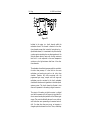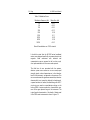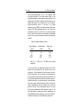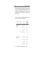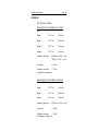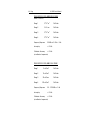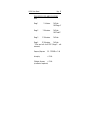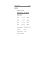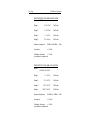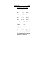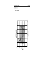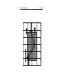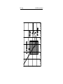
1
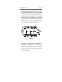
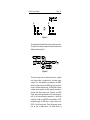
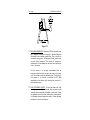
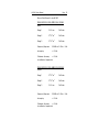
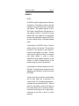
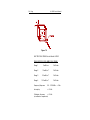
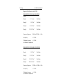
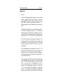
HI-3000 SERIES
Broadband Isotropic
Field Strength Meter
User's Manual
Copyright
Manual #600045B 05/96
© 1991 Holaday Ind. Inc.
$16.00
Revision Record
Manual # 600045B
Broadband Isotropic
Field Strength Meter
Revision
--A
B
Description
Preliminary Release
HI-3012 LFH
CE Approval
Date
8/91
1/95
5/96
TABLE OF CONTENTS
1.0 SYSTEM OVERVIEW . . . . . . . . . . . . . . . . . . 1
1.1 INSTRUMENT DESIGN . . . . . . . . . . . . . 2
2.0 OPERATING INSTRUCTIONS . . . . .
2.1 INTRODUCTION . . . . . . . . . .
2.2 UNPACKING AND INSPECTION
2.3 OPERATING INSTRUCTIONS . .
2.4 UNITS OF MEASURE . . . . . . .
2.5 EXPOSURE GUIDELINES . . . . .
.
.
.
.
.
.
.
.
.
.
.
.
.
.
.
.
.
.
.
.
.
.
.
.
.
.
.
.
.
.
.
.
.
.
.
.
.
.
.
.
.
.
3
3
3
4
6
8
3.0 MAINTENANCE . . . . . . . . . . .
3.1 INTRODUCTION . . . . . . .
3.2 BATTERY STATUS . . . . .
3.3 REPLACING BATTERIES . .
3.4 UNIT COMPLETELY DEAD
.
.
.
.
.
.
.
.
.
.
.
.
.
.
.
.
.
.
.
.
.
.
.
.
.
.
.
.
.
.
.
.
.
.
9
9
9
9
10
4.0 SYSTEM DESCRIPTION . . . . . . . . . .
4.1 INTRODUCTION . . . . . . . . . . .
4.2 INSTRUMENTATION OVERVIEW
4.3 ELECTRONICS PACKAGE . . . . .
4.4 SIGNAL FLOW . . . . . . . . . . . .
4.5 AUTOMATIC ZERO . . . . . . . . .
4.6 ERRORS . . . . . . . . . . . . . . . . .
.
.
.
.
.
.
.
.
.
.
.
.
.
.
.
.
.
.
.
.
.
.
.
.
.
.
.
.
.
.
.
.
.
.
.
.
.
.
.
.
.
.
.
.
.
.
.
.
.
.
11
11
11
11
12
17
20
5.0 SPECIFICATIONS . . . . . . . . . . . . . . . . . . . 25
5.1 SYSTEM CHARACTERISTICS . . . . . . . 25
6.0 WARRANTY SERVICE . . . . . . . . . . . . . . . .
6.1 LIMITED WARRANTY . . . . . . . . . . . . .
6.2 INSTRUCTIONS IN CASE OF DEFECT . .
6.3 CLAIM FOR DAMAGE IN SHIPMENT TO
ORIGINAL PURCHASER . . . . . . . . . . .
27
27
27
28
7.0 TECHNICAL NOTES . . . . . . . . . . . . . . . . . . 29
7.1 LOW FREQUENCY MEASUREMENTS . . 29
7.2 MRI MEASUREMENTS . . . . . . . . . . . . 30
7.3 HIGH STANDING WAVES . . . . . . . . . . 30
APPENDIX 1 . . . . . . . . . . . . . . . . . . . . . . . . . . 31
HI-3001 . . . . . . . . . . . . . . . . . . . . . . . . . . 31
APPENDIX 2 . . . . . . . . . . . . . . . . . . . . . . . . . . 35
HI-3002 . . . . . . . . . . . . . . . . . . . . . . . . . . 35
APPENDIX 3 . . . . . . . . . . . . . . . . . . . . . . . . . . 37
HI-3003 . . . . . . . . . . . . . . . . . . . . . . . . . . 37
APPENDIX 4 . . . . . . . . . . . . . . . . . . . . . . . . . . 39
HI-3004 . . . . . . . . . . . . . . . . . . . . . . . . . . 39
APPENDIX 5 . . . . . . . . . . . . . . . . . . . . . . . . . . 41
HI-3005 . . . . . . . . . . . . . . . . . . . . . . . . . . 41
APPENDIX 6 . . . . . . . . . . . . . . . . . . . . . . . . . . 43
HI-3012 . . . . . . . . . . . . . . . . . . . . . . . . . . 43
APPENDIX 7 . . . . . . . . . . . . . . . . . . . . . . . . . . 45
ELECTRIC FIELD PROBES . . . . . . . . . . . . . . 45
APPENDIX 8 . . . . . . . . . . . . . . . . . . . . . . . . . . 49
MAGNETIC FIELD PROBES . . . . . . . . . . . . . 49
APPENDIX 9 . . . . . . . . . . . . . . . . . . . . . . . . . . 53
ANSI Standards . . . . . . . . . . . . . . . . . . . . 53
ACCESSORIES . . . . . . . . . . . . . . . . . . . . . . . . . 57
RECORD OF SERIAL NUMBERS . . . . . . . . . . . . . 59
Limited Warranty
Holaday Industries, Inc. warrants each model HIn3000 Series
Broadband Isotropic Field Strength Meter to be free from defects
in material and workmanship for a period of one year from the
date of shipment to the purchaser. This warranty extends to the
original purchaser only, and does not apply to the batteries or to
any products or parts subject to misuse, neglect, accident,
unauthorized service or abnormal conditions of operation.
In the event an instrument covered by this warranty fails,
Holaday Industries, Inc. will, without charge, repair and
recalibrate the instrument if returned to their factory within one
year of the original purchase—provided that Holaday Industries'
examination discloses, to its satisfaction, that the product is
defective. Holaday Industries, Inc., may, at its option, replace
the product in lieu of repair. If the defect was caused by misuse,
neglect, accident, unauthorized service or abnormal conditions of
operation, repairs will be billed at a nominal cost. In such cases,
an estimate will be provided before work is started, if requested
by the purchaser.
For warranty service, contact Holaday Industries, Inc. Provide
the serial number of the instrument and complete details
regarding the failure mode. You will then be given either service
information or shipping instructions. Return the instrument to
the factory, transportation prepaid. Repairs will be made at the
factory and the instrument will be returned to you, transportation
prepaid. Holaday Industries, Inc., assumes no responsibility for
loss of, or damage to, products in transit.
Warning!
EXTREME CAUTION IS ADVISED WHEN WORKING IN
ENVIRONMENTS WHERE HIGH-INTENSITY ELECTROMAGNETIC
FIELDS MAY EXIST AND WHERE CONTACT WITH HIGH VOLTAGE
OR HIGH CURRENT CIRCUITS OR APPARATUS IS POSSIBLE.
ACCIDENTAL CONTACT WITH OBJECTS OR CIRCUITS OPERATING
AT HIGH VOLTAGES OR HIGH CURRENTS CAN BE LETHAL!
HOLADAY INDUSTRIES, INC. ASSUMES NO LIABILITY FOR ANY
DAMAGES OR PERSONAL INJURY WHICH MAY RESULT FROM
HI-3000 Series Manual
1.0
Page - 1
SYSTEM OVERVIEW
The Holaday HI-3000 Series Broadband Isotropic Field
Strength Meters are designed primarily for field use to
measure both electric and magnetic fields. Each model has
unique characteristics optimizing its performance for a
particular use. The models in the HI-3000 Series are as
follows:
HI-3001
An electric field meter having a wider dynamic range. The
GRE and STE electric field probes, standard with this unit,
provide measuring capabilities from as low as 10 V2/m2 to
107 V2/m2, or 60 dB range. It is possible to add either the
CH Magnetic Field probe or the HSE High Sensitivity
Electric Field probe to the HI-3001 as an option.
HI-3002
A midline instrument for most general RF field strength
measurements where both electric and magnetic fields
must be measured. The HI-3002 system includes the STE
Electric Field probe and the CH Magnetic Field probe. It is
possible to add the LFH Magnetic Field probe to the HI3002 as an option.
HI-3003
The HI-3003 is a special purpose laboratory instrument
usually used in special purpose applications. The unit is
unique in providing three meter panel mounted axis
selection switches. Any single probe sensing axis or any
combination of axes may be selected for field polarization
or other special measurements. The IME Electric field probe
is standard on the HI-3003, however, any single probe in
the Holaday Broadband RF instrumentation line can be
installed on the unit.
HI-3004
The HI-3004 is the High Sensitivity Electric Field instrument
in the Holaday line. This meter comes standard with the
2 - Page
HI-3000 Series Manual
HSE High Sensitivity Electric Field probe for measurements
as low as one (1) Volt/meter full scale. As an option, the
STE Electric Field probe can be installed on the HI-3004 to
increase the measurement range.
HI-3012
The HI-3012 offers the features of the HI-3002 but with
two new probes to meet the new ANSI C95 RF exposure
standards for uncontrolled population exposures. The MSE
Electric Field probe and the HCH Magnetic Field probe
provide sensitivity below 0.05 mW/cm2. With capability of
measuring equivalent power density levels up to 377
mW/cm2, the HI-3012 essentially covers the full ANSI
range.
1.1 INSTRUMENT DESIGN - The design of the E-field probe is
based on the diode-dipole antenna developed by Bowman
of NBS [now NIST (National Institute of Science and
Technology)], Boulder, Colorado. The use of three mutually
orthogonal dipoles provides isotropic response. The total
field strength at the probe is displayed, regardless of the
field orientation or probe receiving angle. The probes are
extremely durable and will withstand overloads of 800% of
full scale. Similarly, the magnetic field probes are comprised
of three concentric, mutually orthogonal, pickup loops.
The instrumentation package contains the battery pack,
electronic circuit boards, analog meter and other front panel
features. These include 1) peak hold memory switch, 2)
range selector switch, 3) battery status light, 4) over range
light, 5) audio output, and 6) recorder output. There is no
zero adjust knob, since the instrument has full time
automatic zeroing. There is no need to place the probe in a
zero field condition in order to zero the meter.
HI-3000 Series Manual
2.0
Page - 3
OPERATING INSTRUCTIONS
2.1 INTRODUCTION - This section contains instructions for the
use of the instruments, including an explanation of all the
features of the instruments, and information on converting
units of measure. Refer to the Appendix sections for
information specific to a particular model of broadband
meter.
2.2 UNPACKING AND INSPECTION - HI-3000 instruments are
shipped in a protective carrying case. The foam insert is
designed to provide storage for each component of the
system. The white foam block on the instrument handle
should be saved and used each time the instrument is
transported in the carrying case. Each HI-3000 instrument
contains the following:
1
HI-3000 instrumentation package with standard
battery pack (14 alkaline C cells) (Nicad battery
pack optional)
RF Probe(s) - see the probe selection matrix (figure 1)
for the standard probes provided with each unit.
1
Acoustic headset
1
Probe handle and cable assembly, five (5) feet in
length. (A 20 foot resistive extension cable is
provided standard with the HI-3003 in the place of
the cable and handle assembly).
1
User’s Manual
4 - Page
HI-3000 Series Manual
Note:
One optional probe can be added to an HI-3000 Broadband
Meter.
PROBES
MODEL NO.
HSE
GRE
CH
LFH
HI-3001
OPT STD
OPT
OPT
STD
HI-3001A
OPT STD
OPT
OPT
STD
STD
OPT
STD
OPT
OPT
HI-3002
HI-3003
OPT OPT
HI-3004
STD
HI-3005
IME
STD
STE
HCH MSE
OPT
OPT
STD
HI-3012
STD
OPT
STD STD
Figure 1
2.3 OPERATING INSTRUCTIONS
NOTE: The probes are individually calibrated to a specific
broadband instrument. Do not interchange probes between
HI-3000 series instruments.
2.3.1
Select the probe for the appropriate field being
measured. Insert the probe into the handle and, with
light pressure, rotate the probe until the alignment
marks meet and the keyway is felt; then fully seat
the probe in the handle connector. Secure the probe
in the handle by tightening the locking collar.
2.3.2
Turn the selector switch to the desired range. The
probes are color coded and correspond to the colored
scale multipliers selected by the range selector switch
on the front panel.
HI-3000 Series Manual
Page - 5
2.3.3
The "Battery" indicator LED will blink when the unit
is turned on and the batteries are good. When the
battery voltage drops below a safe operating level,
the LED will light steadily and will not blink. The
battery pack consists of 14 C cells and will provide
approximately 30 hours of continuous use or up to
40 hours of intermittent use.
2.3.4
Operate the Peak Hold switch to clear the memory.
There is no zero adjust since the unit has automatic,
full-time self-zeroing capability.
2.3.5
The memory is active any time the instrument is on,
continually being updated with the highest reading
observed. The memory reading can be called for at
any time by operating the peak hold switch. The
reading obtained will be the highest reading observed
since the last switch operation. Releasing the switch
automatically clears and zeros the memory. The time
constant of the memory circuit is much faster than
the circuits driving the analog meter and the recorder
output, which enables the memory to capture a
higher peak reading on a fast rise time pulse.
Therefore, the memory reading may appear higher
than the meter needle indication. Since a timeaveraged signal is important in making safety
measurements, the actual meter indication or
recorder output will usually provide a more suitable
reading.
2.3.6
The "Over Range" LED will light should any of the
following conditions occur: a) the integrated signal is
greater than full scale, b) the peak of any amplitude
modulation is greater than the top of the diode
shaping ROM, c) any common mode signal is present
which is large enough to cause the front end amplifier
to malfunction. An audible alarm will also be heard
through the headset when any of these conditions
occur. In the event of any over range condition
6 - Page
HI-3000 Series Manual
simply switch to the next higher range. The meter, of
course, will automatically re-zero itself.
2.3.7
On the lower left of the front panel there is a port for
driving the headset. The repetition rate of the ticking
sound is proportional to the meter reading and allows
the operator to listen for the high field region while
observing the probe location.
2.3.8
On the left side of the front panel there is a BNC
recorder output jack. The signal available at this port
is calibrated to one volt for full scale indication. The
source impedance is 5K ohms.
2.3.9
Although it is recommended that the unit be turned
OFF to change probes, no damage will occur if the
unit is on while changing probes. While handling
probes, it is important to eliminate the possibility of
static discharge to the probe connector while the
probe is not plugged in.
2.4 UNITS OF MEASURE - The analog meter on HI-3000
instruments generally displays |FSU|2 which means field
strength units squared. When using an E-field probe, the
units are V2/m2 and when using an H-field probe, the units
are A2/m2. Refer to the Appendix for special information on
the HI-3001A, the HI-3003, and the HI-3004. The HI3001A and the HI-3004 display in units of Volts/meter
(V/m) and the HI-3003 displays in mW/cm2.
In the far-field region (distances greater than several wave
lengths from an RF source), the E and H fields are in phase
and vary predictably with distance from the source,
creating a uniform plane wave condition. The ratio of E/H
is constant and has the value of 377 ohms which is termed
the impedance of free space.
HI-3000 Series Manual
Page - 7
In the near-field region both the E and H field strengths vary
greatly with small changes in distance from the source, and
the ratio of E/H is not constant. Therefore, the standards
have been written specifying the measurement of both
Electric and Magnetic fields. Each must be measured
independently regardless of the units of measure displayed
on the meter. For measuring fields at frequencies above
300 MHz, an assumption of near field conditions is made
and only the electric field component of the EM field is
measured. It is generally not feasible to measure free space
magnetic fields above 300 MHz.
In the far field, the power density can be calculated from
either the E or the H field by using 377 ohms, the
impedance of free space, as follows:
E2
377
= power density (W/m2)
H2 x 377 = power density (W/m2)
Converting W/M2 to mW/cm2, these equations become:
E2
3770
=
power density (mW/cm2)
H2 x 37.7 = power density (mW/cm2)
8 - Page
HI-3000 Series Manual
2.5 EXPOSURE GUIDELINES
2.5.1
In the United States, the most commonly applied
standard for RF exposure is the ANSI C95.1-1982
(American National Standards Institute). This
standard is in the process of being revised and a
"Final-Final" draft is in circulation. For your
information, summary information on both the 1982
version and the proposed "1991 Revision" are
included in Appendix 9.
Refer to your National Standards Organization or
contact Holaday Industries, Inc. for information on
standards in other countries.
HI-3000 Series Manual
3.0
Page - 9
MAINTENANCE
3.1 INTRODUCTION - This section contains instructions for
routine maintenance and minor fault isolation.
3.2 BATTERY STATUS - If the battery status LED is glowing
steady, the batteries must be replaced or recharged (see
below).
3.3 REPLACING BATTERIES
3.3.1
Standard Battery Pack - The standard battery pack
consists of 14 alkaline C cells. The battery holder is
fastened to the bottom of the inner instrumentation
housing. Unsnap the four latches holding the outer
instrumentation housing and remove it. Holding the
meter upside down, slide off the retaining strap and
remove old batteries. Replace batteries, observing
the polarity as shown in the bottom of the battery
holder. Slide the retainer back into place. Replace the
outer instrumentation housing taking care not to
pinch the wires or battery clips.
NOTE: If there are more than one meter present, note
that the serial number is written on the battery cover
and the serial label is on the outside can. Care must
be used not to mix them up.
3.3.2
Rechargeable NiCad Option - The NiCad battery pack
is also composed of 14 C size cells. It can be
recharged by plugging in the charger which is
supplied with this option. The meter normally cannot
be operated while recharging the batteries. The
charger operates on either 115 or 220 VAC,
50/60Hz. See the battery charger manual for the
voltage selection procedure. The NiCd battery charger
requires 24 hours to recharge a fully discharged
battery.
10 - Page
HI-3000 Series Manual
The NiCad battery pack is in the bottom of the outer
instrumentation housing. If it becomes necessary to
replace the NiCad pack, unsnap the four latches
holding the outer instrumentation case and remove it.
Lift out the NiCad pack and disconnect the two leads
coming from it. One lead has an in-line connector and
the other an in-line fuse holder. Insert the new
battery pack and reconnect both leads. Replace the
inner housing, being careful not to pinch any wires.
3.4 UNIT COMPLETELY DEAD - If the battery status LED does
not light or blink when the selector switch is turned on, the
battery voltage is too low, or the fuse is open. Refer to 3.3
to open the unit for access to the fuse. If the fuse is good,
the batteries should be replaced or recharged. If the fuse
is open, check for pinched or shorted wires or defective
connections. Replace the fuse (3ag, 1/2 amp, slow blow).
If the fuse blows again, the unit should be returned to the
factory for repair.
CAUTION: The latches which hold the outer
instrumentation case can exert considerable force.
Make certain the case is properly fitted to the front
panel before securing latches or the front panel will
become deformed. In addition to possible mechanical
damage, the effectivity of the RFI seal may be lost.
HI-3000 Series Manual
4.0
Page - 11
SYSTEM DESCRIPTION
4.1 INTRODUCTION - The HI-3000 is a portable, rugged, easyto-use instrument with a wide dynamic range. It employs
an internal digital memory to capture the highest reading
observed for display, when desired, on the unit's analog
meter. It also has automatic full-time zeroing of the meter
to eliminate the effects of offset, noise pickup, and drift
while measurements are being made.
4.2 INSTRUMENTATION OVERVIEW - The front panel controls
of the HI-3000 are relatively simple (see figure 2). Most
prominent is the range selector switch. There are four
ranges for E-field readings and four ranges for H-field
readings. The four ranges are selected by the rotary range
selector switch. The analog meter displays the reading in
field strength units squared. The analog signal is also
available at the recorder output jack, which is calibrated for
one volt output for full-scale meter deflection. The output
is also converted to an audio signal, which is a ticking
sound proportional to meter deflection. LED indicators show
over range conditions and battery status. The momentary
switch labeled peak hold is used to recall the highest
reading from the memory.
Figure 2
4.3 ELECTRONICS PACKAGE - The electronics package
consists of three circuit boards: the front panel board, the
digital board and the analog board (see figure 3).
12 - Page
HI-3000 Series Manual
Figure 3
Contained on the front panel board are three switching
power supplies, the meter driver, a battery low indicator
driver and sense circuits, and audio and recorder output
driver circuits. The digital board contains the circuitry which
sums the three orthogonal channels and also contains the
stored curve reconstruction circuit necessary to reconstruct
the field present at the antenna. The analog board contains
the necessary multiplexing and scaling circuits required to
condition the signal for conversion to a digital word by the
A/D converter, which is also contained on the analog board.
The entire unit is powered by a single voltage battery pack
consisting of 14 alkaline batteries. An optional rechargeable
NiCad battery pack is also available.
4.4 SIGNAL FLOW - The operation of the HI-3000 series
broadband meters can best be understood by following a
signal through the meter.
The equivalent circuit of the antenna system can be seen in
figure 4. It should be noted that the antenna and diode
assembly is simply a short dipole terminated by a diode
detector. The 0.4 pf capacitances represent the equivalent
capacitance of the short dipole antenna. The diode in this
case is modeled as an ideal diode. The 10,000 ohm
resistances represent that section of the high resistance
feed system that occurs before any distributed capacitance
is associated with the feed system. The 6 pf capacitance
represents a lumped element model of the distributed
HI-3000 Series Manual
Page - 13
capacitance of the high resistance feed line. The 1 megohm
resistances are the series resistances of the high impedance
lines and the 60 pf capacitance is the capacitance found in
the multiple conductor shielded line. The 10 megohm
resistances are the input impedances of the differential
amplifier. The entire feed system therefore looks like a peak
detector followed by a low pass filter. This low pass filter
has a cutoff frequency of approximately 400 Hz.
Figure 4
Each element of the feed system is connected to a
preamplifier. The preamplifiers are differential input,
matched and zeroed (see figure 5), and drive a multiplexer
which takes the individual channels and assigns a time slice
to them (see figure 6).
14 - Page
HI-3000 Series Manual
Figure 5
Figure 6
The sampling rate for this multiplexer is approximately 30
KHz, giving each preamplifier a sample rate of
approximately 8 KHz. Figure 7 is a graph representing the
time sliced input signal X,Y,Z. The multiplexer then feeds
a programmable gain section. The gain is selected via
MOSFET switches controlled by the front panel rotary range
switch. The programmable gain stage then drives a sample
and hold circuit. The sample and hold merely samples the
incoming signal at a prescribed time and holds it until the
next sample is updated (see figure 7).
HI-3000 Series Manual
Page - 15
Figure 7
The sample and hold feeds the analog to digital converter.
The output of the analog to digital converter now drives the
digital board (see figure 8).
Figure 8
The data coming from the analog board forms a digital
word whose value is proportional to the diode output
voltage. This, when applied as an address to the ROM,
defines a unique location in the ROM, due to the monotonic
nature of the diode transfer curve. The ROM itself contains
numbers which represent the field strength necessary to
generate that diode output level. Therefore, the ROM
output yields a true representation of the field strength of
each of the three orthogonal components. It should be
noted that in order for the ROM to accommodate a 100%
modulated signal, the ROM has to convert values up to
400% of the full scale value. These field strength values
then go into an adder section. The adder section is
16 - Page
HI-3000 Series Manual
composed of an adder and a latch, comprising a bite wide
serial adder. Figure 9 is representative of the sequence in
which the additions occur. Upon sampling channel X, the
latch is initially cleared. X is then converted by the ROM
and applied to the A input of the adder. Since the output
latch is initially cleared and is applied to B input, the sum
port of the adder contains only X.
ROM
Input
ROM
Output
Adder
Output
Adder
Latch
Sum
Latch
1
X
X*
X*
-0-
(X + Y + Z)T-1
2
Y
Y*
X* + Y*
X*
"
3
Z
Z*
X* + Y* + Z*
X* + Y*
"
4
)
0
0
0
(X + Y + Z)T
5
X
X*
X*
0
"
6
Y
Y*
X* + Y*
X*
"
* - Value after SCR
Figure 9
This is stored in the latch. Y is now applied to input A and
the output of the latch, which contains X, is applied to the
B input. Therefore, the sum contains X plus Y. This is
continued one more iteration so that the sum of the adder
contains X plus Y plus Z. At this point, since the ROM
contained the square of the field strength in each of the
three coordinates, as defined by the diode output, the sum
of the adder contains a number representing the space
power density. This number is then latched in an output
latch found directly to right of the adder.
HI-3000 Series Manual
Page - 17
The two boxes directly below the output latch labeled
comparator and peak hold latch make up the peak hold
function. The output of the adder is applied to the A input
of the comparator and the latch labeled peak hold latch is
applied to the B input of the comparator. When the
incoming signal on A is greater than the signal on B, A>B
output will go high thus latching the new incoming signal.
Therefore the latch contains the word which is
representative of the maximum signal received by the
meter. The multiplexer found to the right of these latches
simply selects the current output latch or the peak hold
latch. The multiplexer drives a digital to analog converter
which converts the digital word back into an analog signal
for driving the meter movement and the recorder output. It
should be noted, however, that the peak hold function
captures only the modulation envelope that is passed by the
probe input transmission line. Since the transmission line
has a rolloff of 400 Hz, the peak hold will see a modulation
envelope as filtered by a single pole 400 Hz low-pass filter.
The analog meter on the other hand has a rolloff
characteristic of approximately 1 Hz. Therefore it is
possible that the actual modulation envelope may be higher
than the analog meter deflection.
4.5 AUTOMATIC ZERO - This feature eliminates the need for a
zero adjustment and eliminates temperature drift problems
associated with other available instrumentation. The
automatic full time zero also allows the operator to use the
meter immediately upon turning it on. Also, it is not
necessary to remove the meter to a "ZERO FIELD"
environment to check its zeroing.
The operation of the automatic zeroing can be seen in
figure 10.
18 - Page
HI-3000 Series Manual
Figure 10
Included in the meter is a fourth channel called the
redundant channel. This channel is identical to the other
three channels except that instead of being driven by a
dipole diode element, it is terminated in the probe head by
a carbon resistor simulating the zero bias impedance of the
Schottky Barrier diode in series with the high resistance
feed line. It is also subjected to the same temperature
variations as the high resistance feed lines of the other
three channels.
The redundant channel feeds a preamp which is matched to
the other three preamps. It is then fed into the same
multiplexer and analog gain path as the other three
channels. Therefore any drifts associated with the
programmed gain stage, sample and hold stage and
multiplexer are also contained in the fourth redundant
channel with the absence of signals due to the diode-dipoleantenna system. This fourth channel is allocated a time
slice and is presented to the analog to digital conversion.
The output of the analog to digital converter is a digital
word which represents only the amount of signal which is
due to common mode pickup and drifts of the different gain
stages. This word should ideally be equal to zero with any
word other than zero representing an unwanted noise or
drift. If a value other than zero occurs, an integrator is
charged up which subtracts this offset. Thus, a closed loop
HI-3000 Series Manual
Page - 19
has been generated which subtracts analog zero shifts and
gain shifts from the remaining three channels.
The only circuits prone to zero shifts are the analog circuits.
The digital circuits following do not drift. The drifts
associated with the final digital to analog converter are
insignificant compared to the signal levels present.
Therefore, the entire meter is protected against zero drift
and temperature variation drift.
An auto-zeroing technique of this nature yields a zeroing
signal that oscillates about true zero at 1/2 the sample rate
of the instrument. Step sizes correspond to the amount of
charge the integrator acquires during one correction
interval, and the slope at which the integrator can charge
determines the maximum slope the automatic zeroing
circuit can follow (see figure 11). This rate of change is
many times faster than the temperature and zero drifts,
making the zero very stable and accurate during use. When
the instrument is first turned on, however, or when
changing scales, large offsets may be introduced which
may take a second or two for the auto-zero circuit to
correct.
Figure 11
20 - Page
HI-3000 Series Manual
4.6 ERRORS - Errors associated with the HI-3000 series meters
are generated primarily by two sources. The first is the
instrumentation electronics itself and the second is
associated with the limitations of the sensing probe.
Those errors caused by the instrumentation electronics
section of the HI-3000 are primarily due to non-linearities
in the analog to digital and the digital to analog converters,
the look-up ROM, and the analog meter movement itself.
The maximum total error of the electronics package is
about three percent. Errors associated with the limitations
of the probe fall into three categories; those of the
frequency response of the antenna, modulation response
errors and multiple frequency detection errors.
The out-of-band response of the electric field probes
exhibits a fairly sharp rolloff. The high end response drops
due to the selective loading of the dipole and the diode
package characteristics. The low frequency rolloff is
predominantly controlled by the shunt capacitance of the
diode and the stray capacitance associated with the initial
section of the high resistance feed lines. At frequencies
near the low end of the response band feed lines are not
sufficiently transparent and act as an unwanted antenna
(see section 7.1). Similarly, the frequency response of the
magnetic field probes are dropping at frequencies below the
lower limit. At frequencies above the upper limit, however,
the response of the magnetic field probes exhibits out-ofband resonances, causing the response to rise sharply.
Below 1.0 MHz, any electrical unbalance of the feed lines
or capacitive coupling to electrodes supporting the electric
field being measured can cause false readings. It is
important that the user of any instrument having high input
impedances associated with the detection system, such as
the HI-3000, be aware of the general spectrum of the fields
being measured. A prime example of this would be the
attempt to measure the low frequency electromagnetic
radiation of a CRT with the HI-3000. A CRT generates a
HI-3000 Series Manual
Page - 21
substantial field at about 15 KHz with a decaying spectrum
content to about 100 KHz. These signals can induce
voltages into the detection system via the feed lines rather
than the antennas and hence it is impossible to correlate
the reading of the instrument with a meaningful calibration.
The same may be said about the case where measurements
are attempted in the presence of extremely high 60 Hz
fields such as would be found under very high voltage
transmission lines (see section 7.1).
A second error occurs in the form of modulation error. As
was noted earlier, the detected signals are fed to the
instrumentation package by means of high resistance lines.
These lines and the associated distributed capacitance form
a low-pass filter between the detection element and the
signal shaping circuit. Because the associated circuits
following the detection diode cannot follow the
instantaneous RF signal, the input to the look-up table will
be different from the ideal and the corresponding output
will, in general, be lower for the peaks and higher for the
valleys. This will result in slight errors for low levels of
modulation below 400 Hz and significant errors for 100
percent modulation at higher modulation frequencies. Table
1 shows the comparison of 100 percent sinusoidal
modulation to a pure cw case.
22 - Page
HI-3000 Series Manual
Table 1: Modulation Errors
Modulation Frequency (Hz)
20
50
100
200
500
1000
2000
5000
10000
Meter Error (db)
+0.61
+0.51
+0.51
+0.31
0.00
-0.11
-0.22
0.00
+0.61
Note: All modulations are 100% sinusoid
It should be noted that the HI-3000 series broadband
meters were designed specifically to measure electric and
magnetic fields associated with industrial and
communication uses as opposed to the low duty cycle,
short pulse modulation of microwave radar systems.
The third form of error associated with the antennadetector system occurs when two or more nearly equal
strength signals, whose frequencies are in the detection
band of the instrument, are imposed on the antenna. This
error occurs because the signals are summed by a detection
element which is not, except for relatively low level signals,
a square law detector. Instead, the diode along with its R-C
circuit acts very much as a peak detector relying on the
look-up ROM to restore square law characteristics over
most of the upper dynamic range of the instrument. The
typical transfer characteristic of the family of diodes used
in the 3000 series instruments is shown in figure 12.
HI-3000 Series Manual
Page - 23
Figure 12
The instrument will therefore read higher than true. This is
shown by a simple example as follows. Assume that there
are two electric fields impinging on the probe. Let the
amplitude of these fields be A1 and A2 accordingly. It can
be seen that the effective power density is proportional to
A1 squared plus A2 squared, ie., the sum of the squares of
the fields at the point of reception (equation 1A). If we
assume that diode detector elements of the probe are
operating in the purely linear region of the diode's curve
and the squaring is done after the two signals are summed,
it can be seen that equation 1B represents the formulation
of the effective power density. Equation 1C compares
equation 1A and 1B and it can be seen that
(2xA1xA2)/(A12 + A22) is the error term.
(1A) A12 + A22
(1B) (A1 + A2)2 = A12 + 2A1A2 + A22
(1C) (A12 + 2A1A2 + A22) - (A12 + A22) = 2A1A2
A12 + A22
A12 + A22
24 - Page
HI-3000 Series Manual
This error term approaches 1 as A1 = A2. Therefore, with
the probe exposed to two equal signals falling in the
nondispersive region of the frequency response curve of the
antenna and if the diode is acting as a peak detector in the
ideally linear region of the diode curve, the instrument
would theoretically yield a +3 db error. In a careful
evaluation using a TEM cell, the Environmental Protection
Agency (EPA) Electromagnetics Branch, Las Vegas, has
measured this effect for the case of two and three equal
electric fields. These results are compared to the idealized
worse case using the assumptions previously discussed
(table 2).
Table 2: Multiple Frequency Errors
Meter Reading
(V/M)2
48
460
6000
Ideal Reading
(V/M)2
40
400
4000
Meter Error
(db)2
+0.79
+0.61
+1.76
Note: F1 = 1 MHz, F2 = 100 MHz, both of equal
amplitude
It can be seen that the experimental results are far less
severe than that predicted by the simplistic worse case
calculations. This is explained for the most part by the fact
that the diode does, in fact, operate over a characteristic
curve which does approximate square law response at the
low field levels and never reaches the pure linear region. It
should be noted that, in a practical sense, one would rarely
find nearly equal multiple frequency fields in health and
safety measurements and any resulting error would be
positive in nature. This would prevent errors of the type
which might underestimate field strengths. Again, if the
user does observe measurement levels approaching the
recommended maximum exposure, care must be taken to
consider the spectrum of the fields being measured.
HI-3000 Series Manual
5.0
Page - 25
SPECIFICATIONS
5.1 SYSTEM CHARACTERISTICS
5.1.1
Full-time automatic zero! Even while performing
measurements.
5.1.2
Peak hold memory circuit
5.1.3
LED indicators for overload and battery status.
5.1.4
Audio output, ticking rate is proportional to meter
deflection.
5.1.5
Recorder output, 0-1 volt corresponding to meter
deflection.
5.1.6
Instrumentation readout in field strength units (FSU)
squared.
5.1.7
Operates on 14 C size batteries.
5.1.8
Size (instrumentation package): 8-1/8" x 5-1/8" x 47/8".
5.1.9
Weight: 6.5 pounds
5.1.10 Total length of probe and handle (with probe
inserted): 30 inches.
5.1.11 Overload: can withstand CW signal to 800% of full
scale of maximum probe range.
26 - Page
HI-3000 Series Manual
HI-3000 Series Manual
6.0
Page - 27
WARRANTY SERVICE
6.1 LIMITED WARRANTY - Holaday Industries, Inc. warrants
each HI-3000 series Isotropic Broadband Field Strength
Meter to be free from defects in material and workmanship
under normal use and service for a period of one (1) year
from date of shipment. This warranty extends to the
original purchaser only. This warranty does not apply to
fuses, batteries, or any products or parts that have been
subject to misuse, neglect, accident, or abnormal conditions
of operation.
In the event of instrument failure covered by this warranty,
Holaday Industries, Inc. will repair and recalibrate the
instrument if returned to their factory within one (1) year of
original purchase, provided the warrantor's examination
discloses to its satisfaction that the product was defective.
The warrantor may, at its option, replace the product in lieu
of repair. With regard to any instrument returned within the
warranty period, said repairs or replacement will be made
without charge. If the defect was caused by misuse,
neglect, accident, or abnormal conditions of operation,
repairs will be billed at nominal cost. In such a case, an
estimate will be submitted before work is started, if
requested.
6.2 INSTRUCTIONS IN CASE OF DEFECT
6.2.1
Notify Holaday Industries, Inc. giving full details of
the difficulty, and include the serial number of the
instrument. On receipt of this information, service
data or shipping instructions will be forwarded to
you.
6.2.2
On receipt of the shipping instructions, forward the
instrument, transportation prepaid to:
28 - Page
HI-3000 Series Manual
Holaday Industries Inc.
Attn. Service Department
14825 Martin Drive
Eden Prairie, MN USA 55344
Repairs will be made at the factory and the
instrument returned to you, transportation
prepaid.
6.3 CLAIM FOR DAMAGE IN SHIPMENT TO ORIGINAL
PURCHASER - The instrument should be thoroughly
inspected immediately upon delivery to the purchaser. All
material should be checked against the enclosed packing
list. Holaday Industries, Inc. cannot be responsible for
shortages against the packing list unless a claim is filed
with the carrier immediately. To obtain a quotation to repair
shipping damage, contact Holaday Industries, Inc. Final
claim and negotiations with the carrier must be completed
by the customer.
HI-3000 Series Manual
7.0
Page - 29
TECHNICAL NOTES
7.1 LOW FREQUENCY MEASUREMENTS - When measuring
electric fields, special procedures must be followed to
maximize the accuracy of measurements near the low
frequency end of the instrument response band. Even
though the feed lines from the probe are as transparent to
RF as possible, they may act as an unwanted antenna,
especially at frequencies below approximately 3 MHz.
When making electric field measurements at these
frequencies, such as around AM broadcast towers, it is
possible to minimize unwanted pickup by placing the probe
handle perpendicular to the field orientation and carefully
coiling the probe cord in the same plane as the probe
handle. Also, the probe should be kept well away from the
body or any object which could cause reflections or reradiation to be picked up by the probe. This scattering of
reflection can cause falsely high readings. It is
recommended that the instrument be placed on a nonconducting support, such as a wooden stepladder or stand.
Back away from the instrument until the reading stabilizes.
The meter scale is easily read from several feet away.
See figure 13 for one suggested method of measurement
near an AM broadcast tower.
30 - Page
HI-3000 Series Manual
Figure 13
7.2 MRI MEASUREMENTS - Measuring RF field strengths near
MRI (Magnetic Resonance Imaging or Nuclear Magnetic
Resonance) units requires special care. This is due to the
extremely strong static (dc) magnetic fields present near
the unit during operation. The concern is in regard to
interference or even damage to the meter unit itself rather
than to the probe.
For this reason, it is strongly recommended that an
extension cable be used to connect the probe to the meter
unit. The extension cable should be at least 10 feet long. In
this manner, it is possible to measure the RF fields
generated by the system while locating the meter unit a
safe distance away.
7.3 HIGH STANDING WAVES - In high field areas with high
standing waves or high reflections, high currents may be
induced in the probe cable and handle. In such areas, it may
be advisable to use a resistive cable such as are provided in
the Holaday Industries extension cables. Contact Holaday
Industries for further information.
HI-3000 Series Manual
Page - 31
APPENDIX 1
HI-3001
The HI-3001 is a broadband electric field strength meter.
With two electric field probes, it provides a wide dynamic
range of E field measurements. It is especially useful for
measurements above 300 MHz where magnetic field
measurements are not generally necessary. An auxiliary
range is available for the addition of an accessory probe.
The accessory probe may be either the HSE high sensitivity
electric field probe or the CH magnetic field probe. The
meter scale is calibrated in field strength units squared
[FSU]2.
The fourth range of the HI-3001 is an auxiliary range not
used by the two standard electric field probes. One
additional probe can be used with the HI-3001 and used on
the auxiliary (AUX) ranges. The two most sensitive range
of the auxiliary probe can be used with the HI-3001. An
attenuator is provided with the additional probe to provide
the second range. To use the first (most sensitive) range
of the additional probe, connect it directly to the meter in
the normal manner. To use the second range of the
additional probe, connect the probe to the attenuator and
the attenuator to the probe handle. This effectively
reduces the sensitivity of the additional probe by a factor of
10. Do NOT use the attenuator with either the GRE or the
STE probes.
The optional HI-3001A version is calibrated in Volts/meter.
The meter scale on the HI-3001A is non-linear in that the
pointer deflection is proportional to the square of the
electric field. The scale graduations are in Volts/meter. This
factor is especially important when using the Recorder
Output signal. The 0-1 VDC signal from the Recorder
Output receptacle is proportional to meter pointer
deflection. A displayed or Recorder Output Signal value is
proportional to Volt2/meter2. To obtain a value in
32 - Page
HI-3000 Series Manual
volts/meter, the square root of the indicated value must be
calculated. Please refer to the following example:
Recorder Output
1.0 Volts
0.9
0.8
0.7
0.6
0.5
0.4
0.3
0.2
0.1
V2/m2
100
90
80
70
60
50
40
30
20
10
V/m
10.0 Full Scale
9.5
8.9
8.4
7.7
7.1
6.3
5.5
4.5
3.2
HI-3000 Series Manual
Page - 33
Electric Field Probes For the HI-3001
PROBE SPECIFICATION, STE E-FIELD PROBE
(Red)
Range 1
105 V2/m2
Full Scale
Range 2
106 V2/m2
Full Scale
Range 3
107 V2/m2
Full Scale
Frequency Response:
0.5 MHz to 5 GHz ± 2 db
Isotropicity:
± 0.5 db
Calibration Accuracy:
± 0.5 db
(at calibration frequencies)
PROBE SPECIFICATION, GRE E-FIELD PROBE
(Green)
Range 1
102 V2/m2
Full Scale
Range 2
103 V2/m2
Full Scale
Range 3
104 V2/m2
Full Scale
Frequency Response:
0.5 MHz to 5 GHz ± 2 db
Isotropicity:
± 0.5 db
Calibration Accuracy:
± 0.5 db
(at calibration frequencies)
34 - Page
HI-3000 Series Manual
HI-3000 Series Manual
Page - 35
APPENDIX 2
HI-3002
The HI-3002 Broadband Field Strength meter is a general
purpose broadband field strength meter for measuring
electric and magnetic fields to current ANSI guidelines.
The HI-3002 is supplied with one E-field probe and one Hfield probe. The E-field probe covers the range from 103 to
107 V2/m2 and the H-field probe covers the range from 0.01
to 100 A2/m2.
An LFH Low Frequency Magnetic Field probe may be added
as an option to the HI-3002. This probe extends the
frequency range for magnetic field measurements down to
500 KHz. When using the LFH probe with the HI-3002,
the readings must be multiplied by the correction factor
listed on the probe. For example, when reading on range 1
using the LFH probe with a correction factor of 8.7 , a
reading of 5 on the meter scale would be multiplied by the
range multiplier (0.01) to obtain a reading of 0.05. This is
multiplied by the probe correction factor to obtain a reading
of 0.44 A2/m2. See Appendix 8 for the LFH probe
specifications.
36 - Page
HI-3000 Series Manual
The following table shows the full-scale readings of each
range in terms of effective power density:
|FSU|2
PWEPD*
(mW/cm2)
CH (H Field) 1
Green
2
0.1 A2/m2
3.77
1.0 A2/m2
37.7
3
10.0 A2/m2
4
100.0 A2/m2
3770
STE(E Field) 1
Red
2
104 V2/m2
2.65
105 V2/m2
26.5
3
106 V2/m2
265
4
107 V2/m2
2653
PROBE
RANGE
377
Note: * Plane Wave Equivalent Power Density
HI-3000 Series Manual
Page - 37
APPENDIX 3
HI-3003
The HI-3003 is specially configured primarily for laboratory
and research use. This model also is chosen for customized
configurations using special probes and/or special meter
scale calibration. The standard configuration of the HI3003 includes a single IME electric field probe and has a
scale calibrated in mW/cm2. A 6 meter (20 foot) probe
extension cable is also standard as is an internal NiCad
battery pack and external battery charger. The HI-3003 can
be custom configured with any of the Holaday broadband
probes.
A unique feature of the HI-3003 is the set of three axis
selection switches on the front panel. This feature allows
the selection of any combination of sensor elements to
provide the signal displayed on the meter. The meter
normally sums the signals from all three of the orthogonal
probe sensing elements to provide an isotropic
measurement of the electromagnetic field present. In some
situations, it is helpful to separately measure the field
polarization along one or more of the sensing axes.
In normal operation, all three axis switches are in the UP or
ON position. To measure using only a single axis, leave the
selected axis switch ON and turn the other two switches
OFF (DOWN).
To align a sensor with a horizontally or vertically polarized
field, the probe handle must be positioned at the
"analytical" angle. This is the angle that the diagonal of a
cube makes with the horizontal plane (35.3°). When the
probe axis, (probe handle), is oriented at this angle, the
three sensing elements will be successively oriented in
horizontal and vertical directions as the probe handle is
rotated about its axis. Refer to figure 14 for further
information.
38 - Page
HI-3000 Series Manual
Figure 14
ELECTRIC FIELD PROBE for the Model HI-3003
PROBE SPECIFICATION, IME E-FIELD PROBE
Range 1
2 mW/cm2
Full Scale
Range 2
10 mW/cm2
Full Scale
Range 3
20 mW/cm2
Full Scale
Range 4
100 mW/cm2
Full Scale
Frequency Response:
0.5 - 1000 MHz ± 2 db
Isotropicity:
± 0.5 db
Calibration Accuracy:
± 0.5 db
(at calibration frequencies)
HI-3000 Series Manual
Page - 39
APPENDIX 4
HI-3004
The HI-3004 Isotropic Broadband Field Strength Meter is
designed primarily to measure low level fields for EMI/EMC
studies. The meter scale on the HI-3004 is calibrated in
Volts/meter. It is important to note that the scale is nonlinear. The meter pointer deflection is proportional to field
strength units squared (Volts2/meter2). The Recorder Output
on the HI-3004 provides a 0-1 VDC signal proportional to
meter deflection, ie., the output signal is proportional to the
square of the reading in Volts/meter. To use the output
readings as Volts/meter, it is necessary to take the square
root of the value and then multiply by the proper scaling
factor.
The probe/handle can be secured to the instrument case by
seating the red handle grip in the clamp on the side of the
meter case. The clamp can be rotated to various probe
orientations by pulling the locking pin and rotating the
holder to the desired position. This allows for convenient
one-hand operation or for stationary, unattended operation.
When the lowest (most sensitive) range is selected, an
indication may occur when no field is present, especially if
the cable is flexed, due to the high gain necessary on this
range. Care must generally be taken when moving the
probe cable to avoid indication artifacts due to the
movement.
For maximum accuracy, the HI-3004 should be allowed to
"warm up" for at least five (5) minutes after turning the
selector switch ON before using.
The HSE High Sensitivity Electric Field probe is standard
with the HI-3004. The STE Electric Field probe is available
as an option.
40 - Page
HI-3000 Series Manual
ELECTRIC FIELD PROBES for the Model HI-3004
PROBE SPECIFICATION, HSE E-FIELD PROBE
(Blue)
Range 1
1 V/m
Full Scale
Range 2
3 V/m
Full Scale
Range 3
10 V/m
Full Scale
Range 4
30 V/m
Full Scale
Frequency Response:
0.5 - 1500 MHz ± 2 db
Isotropicity:
± 0.5 db
Calibration Accuracy:
± 0.5 db
(at calibration frequencies)
PROBE SPECIFICATION, STE E-FIELD PROBE
(OPTIONAL Red)
Range 1
100 V/m
Full Scale
Range 2
300 V/m
Full Scale
Range 3
1000 V/m
Full Scale
Range 4
3000 V/m
Full Scale
Frequency Response:
0.5 MHz to 5 GHz ± 2 db
Isotropicity:
± 0.5 db
Calibration Accuracy:
± 0.5 db
(at calibration frequencies)
HI-3000 Series Manual
Page - 41
APPENDIX 5
HI-3005
The HI-3005 is designed specifically for magnetic field
measurements. With two magnetic field probes, the system
will measure magnetic fields over a frequency range from
0.3 to 300 MHz.
The HI-3005 readout includes a set of three axis selection
switches on the front panel. This feature allows the
selection of any combination of sensor elements to provide
the signal displayed on the meter. The meter normally sums
the signals from all three of the orthogonal probe sensing
elements to provide an isotropic measurement of the RF
magnetic field present. In some situations, it is helpful to
separately measure the field polarization along one or more
of the sensing axes.
In normal operation, all three axis switches are in the UP or
ON position. To measure using only a single axis, leave the
selected axis switch ON and turn the other two switches
OFF (DOWN).
To align a sensor with a horizontally or vertically polarized
field, the probe handle must be positioned at the
"analytical" angle. This is the angle that the diagonal of a
cube makes with the horizontal plane (54.7°). When the
probe axis, (probe handle), is oriented at this angle, the
three sensing elements will be successively oriented in
horizontal and vertical directions as the probe handle is
rotated about its axis. Refer to appendix 3, figure 14 for
further information.
42 - Page
HI-3000 Series Manual
Magnetic Field Probes for the HI-3005:
PROBE SPECIFICATION, CH H-FIELD PROBE
(Green)
Range 1
0.1 A2/m2
Full Scale
Range 2
1.0 A2/m2
Full Scale
Range 3
10.0 A2/m2
Full Scale
Range 4
100.0 A2/m2
Full Scale
Frequency Response:
5 MHz to 300 MHz ± 2 db
Isotropicity:
± 0.5 db
Calibration Accuracy:
± 0.5 db
(at calibration frequencies)
PROBE SPECIFICATION, LFH H-FIELD PROBE
(Black)
Range 1
1.0 A2/m2
Full Scale
Range 2
10.0 A2/m2
Full Scale
Range 3
100.0 A2/m2
Full Scale
Range 4
1000.0 A2/m2
Full Scale
Frequency Response:
0.3 MHz to 10 MHz ± 2 db
Isotropicity:
± 0.5 db
Calibration Accuracy:
± 0.5 db
(at calibration frequencies)
HI-3000 Series Manual
Page - 43
APPENDIX 6
HI-3012
The HI-3012 Broadband Field Strength meter is a general
purpose broadband field strength meter for measuring
electric and magnetic fields to the proposed revision to the
ANSI MPE's (maximum permissible exposures). It is
anticipated that this revised standard will be issued in late
1991.
The HI-3012 is supplied with two new field sensing probes.
The MSE E-field probe provides a 10X increase in
sensitivity over the STE probe to measure to the 0.2
mW/cm2 MPE for uncontrolled exposures. This probe covers
the range from 102 to 106 V2/m2 (10 to 1000 Volts/meter).
The HCH H-field probe also provides an additional 10X
increase in sensitivity over the CH probe to measure to the
reduced MPE's for uncontrolled exposures. This probe
covers the range from 0.001 to 10 A2/m2 (.03 to 3.16
Amps/meter).
An optional LFH probe may be added to the HI-3012. The
LFH probe is calibrated over the existing HCH ranges. A
calibration factor is provided with the probe and readings on
the HCH ranges must be multiplied by the calibration factor
to provide actual values.
On special order, the HI-3012 may have its magnetic field
scales (H Field) calibrated primarily to the optional LFH
probe. In this case, the measurement range of the LFH
probe can be extended up to 1,000 A2/m2 full scale on
range 4. The full scale values on ranges 1, 2, and 3 are
1.0, 10.0, and 100.0 A2/m2 respectively. A calibration
factor of 100 is applied in converting the meter/range
readings to the actual values measured with the LFH probe.
44 - Page
HI-3000 Series Manual
When the HI-3012 is calibrated in this manner, the
sensitivity of the HCH probe is reduced proportionately and
a calibration factor is supplied for this probe also. The
calibration factor is approximately 5. This factor may vary
significantly from the nominal value and may vary from
range to range.
The following table shows the Full-scale readings of each
range in terms of effective power density:
PROBE
RANGE
|FSU|2
PWEPD*
(mW/cm2)
HCH (H Field) 1
Orange
2
0.01 A2/m2
.377
0.1 A2/m2
3.77
3
1.0 A2/m2
37.7
4
10.0 A2/m2
377.0
MSE (E Field) 1
Green
2
103 V2/m2
0.265
104 V2/m2
2.65
3
105 V2/m2
26.5
4
106 V2/m2
265
Note: * Plane Wave Equivalent Power Density
HI-3000 Series Manual
Page - 45
APPENDIX 7
ELECTRIC FIELD PROBES
PROBE SPECIFICATION, STE E-FIELD PROBE
(Red)
Range 1
104 V2/m2
Full Scale
Range 2
105 V2/m2
Full Scale
Range 3
106 V2/m2
Full Scale
Range 4
107 V2/m2
Full Scale
Frequency Response:
0.5 MHz to 5 GHz ± 2 db
1 MHz to 1 GHz ± 1 db
Isotropicity:
± 0.5 db
Calibration Accuracy:
± 0.5 db
(at calibration frequencies)
PROBE SPECIFICATION, GRE E-FIELD PROBE
(Green HI-3001)
Range 1
102 V2/m2
Full Scale
Range 2
103 V2/m2
Full Scale
Range 3
104 V2/m2
Full Scale
Frequency Response:
0.5 MHz to 5 GHz ± 2 db
Isotropicity:
± 0.5 db
Calibration Accuracy:
+ 0.5 db
(at calibration frequencies)
46 - Page
HI-3000 Series Manual
PROBE SPECIFICATION, MSE E-FIELD PROBE
(Green - HI-3012)
Range 1
103 V2/m2
Full Scale
Range 2
104 V2/m2
Full Scale
Range 3
105 V2/m2
Full Scale
Range 4
106 V2/m2
Full Scale
Frequency Response:
0.5 MHz to 5 GHz ± 2 db
Isotropicity:
± 0.5 db
Calibration Accuracy:
± 0.5 db
(at calibration frequencies)
PROBE SPECIFICATION, IME E-FIELD PROBE
Range 1
2 mW/cm2
Full Scale
Range 2
10 mW/cm2
Full Scale
Range 3
20 mW/cm2
Full Scale
Range 4
100 mW/cm2
Full Scale
Frequency Response:
0.5 - 1000 MHz ± 2 db
Isotropicity:
± 0.5 db
Calibration Accuracy:
± 0.5 db
(at calibration frequencies)
HI-3000 Series Manual
Page - 47
PROBE SPECIFICATION, HSE E-FIELD PROBE
(Blue)
Range 1
1 Volt/meter
Full Scale
AUX Range A*
Range 2
3 Volts/meter
Full Scale
AUX Probe B*
Range 3
10 Volts/meter
Full Scale
Range 4
30 Volts/meter
Full Scale
* When used with the HI-3001 (Range B - with
attenuator).
Frequency Response:
0.5 - 1500 MHz ± 2 db
Isotropicity:
± 0.5 db
Calibration Accuracy:
± 0.5 db
(at calibration frequencies)
48 - Page
HI-3000 Series Manual
HI-3000 Series Manual
Page - 49
APPENDIX 8
MAGNETIC FIELD PROBES
PROBE SPECIFICATION,
(Green - HI-3002)
(Yellow - HI-3001)
CH H-FIELD PROBE
Range 1
0.1 A2/m2
Full Scale
Range 2
1.0 A2/m2
Full Scale
Range 3
10.0 A2/m2
Full Scale
Range 4
100.0 A2/m2
Full Scale
Frequency Response:
5 MHz to 300 MHz ± 2 db
Isotropicity:
± 0.5 db
Calibration Accuracy:
± 0.5 db
(at calibration frequencies)
50 - Page
HI-3000 Series Manual
PROBE SPECIFICATION, HCH H-FIELD PROBE
(Orange HI-3012)
Range 1
0.01 A2/m2
Full Scale
Range 2
0.10 A2/m2
Full Scale
Range 3
1.0 A2/m2
Full Scale
Range 4
10.0 A2/m2
Full Scale
Frequency Response:
5 MHz to 300 MHz ± 2 db
Isotropicity:
± 0.5 db
Calibration Accuracy:
± 0.5 db
(at calibration frequencies)
PROBE SPECIFICATION, LFH H-FIELD PROBE
(Black)
HI-3005 / HI-3002*
Range 1
1.0 A2/m2
Full Scale
Range 2
10.0 A2/m2
Full Scale
Range 3
100.0 A2/m2
Full Scale
Range 4
1000.0 A2/m2
Full Scale
Frequency Response:
0.3 MHz to 10 MHz ± 2 db
Isotropicity:
± 0.5 db
Calibration Accuracy:
± 0.5 db
(at calibration frequencies)
HI-3000 Series Manual
Page - 51
PROBE SPECIFICATION, LFH H-FIELD PROBE
(Black)
HI-3012*
Range 1
0.2 A2/m2
Full Scale
Range 2
2.0 A2/m2
Full Scale
Range 3
20.0 A2/m2
Full Scale
Range 4
200.0 A2/m2
Full Scale
Frequency Response:
0.3 MHz to 10 MHz ± 2 db
Isotropicity:
± 0.5 db
Calibration Accuracy:
± 0.5 db
(at calibration frequencies)
*
When used with the HI-3002 and HI-3012, the LFH
Probe is calibrated to the standard H field probe
ranges and a calibration factor applied. The full scale
values listed are approximate and the actual values
may vary by up to 20% from those listed.
52 - Page
HI-3000 Series Manual
HI-3000 Series Manual
APPENDIX 9
ANSI Standards
Page - 53
54 - Page
HI-3000 Series Manual
HI-3000 Series Manual
Page - 55
56 - Page
HI-3000 Series Manual
HI-3000 Series Manual
Page - 57
ACCESSORIES
Description
Alkaline Batteries (Qty. 14)
NiCad Battery Pack
NiCad Battery Charge Assembly
Heavy Duty Carry Case
Replacement Handle and Cable Assembly
Probe Extension Cable
Probe Spacer 13 cm and 14 cm
Fiber Optic Link
Datalogger
HI-3320
Printer (use with HI-3320)
Back Pack
Part No.
30MN1400
30490310
HI-3101A
490988
490333
490939
491002
HI-3113
46DPU-411
445000SX
58 - Page
HI-3000 Series Manual
HI-3000 Series Manual
RECORD OF SERIAL NUMBERS
Meter
Model Number
Serial Number
Date Placed in Service
Probe
Model Number
Serial Number
Model Number
Serial Number
Model Number
Serial Number
Model Number
Serial Number
Model Number
Serial Number
Page - 59
60 - Page
HI-3000 Series Manual
--NOTES--