1
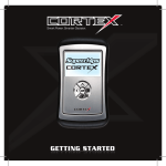
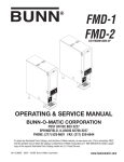
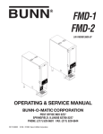
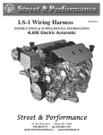
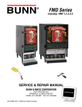
Page 1 of 20 Form 0127H 03/29/07 Superchips Inc. Superchips 2575 MAX Micro Tuner General Motors 01-02 GM CK 4.3L V-6 Gasoline Engine Trucks & SUV Series Vehicle Programming Instructions – Section A PLEASE READ THIS ENTIRE INSTRUCTION SHEET BEFORE YOU PROCEED Thank you for choosing the Superchips Model 2575 MAX Micro Tuner, a remarkable instrument that allows you to install a Superchips performance program specifically tuned for your GM vehicle. You can optionally remove the vehicle speed limiter. Later model vehicles also allow speedometer correction to compensate for tire height and/or gear changes. The 2575 MAX Micro Tuner is intended for use on unmodified stock engines. Use High Octane Fuel The Superchips performance program requires that you use at least 91 octane fuel. Using a lower octane fuel while the performance program is installed may cause detonation that can be harmful to your engine. Superchips Inc. Page 2 of 20 Form 0127H 03/29/07 Refund Policy If for any reason during the first thirty (30) days after your purchase of a new Superchips product (“Product”), you may return it to the place you bought it for a full refund of the purchase price, credit or a replacement Product at the dealer’s discretion. This Guarantee does not apply to products purchased from on-line Internet auctions nor does it apply to Products purchased used. Follow these procedures to get your refund or replacement. 1. If you are returning a MicroTuner or Flashpaq, use the MicroTuner or Flashpaq to return your vehicle to the stock settings for the vehicle. Instructions are included in the user manual. 2. Put the Product back in its original packaging. 3. Make a copy of your sales receipt. The sales receipt must be from the location where you purchased your Product and must include the name of the business, its address, and the part number or description of the applicable Superchips Product. Invoices, credit card statements, or sales receipts from an online payment service company will not be accepted. 4. Return the Product in its original packaging with a copy of the sales receipt to the place of purchase. Superchips, Inc. Limited Warranty What is Covered? This warranty covers any defects in materials or workmanship in any product sold by Superchips or its affiliates through its authorized dealers (“Product”). How Long Does the Coverage Last? This warranty lasts for one (1) year from the date of purchase. Coverage terminates if you sell or otherwise transfer ownership of the Product. What will Superchips Do? Superchips will repair or replace the defective or malfunctioning Product or any defective or malfunctioning part thereof at no charge. This warranty covers parts and labor only. Superchips will reimburse you for all reasonable shipping charges within the first thirty (30) days of purchase. What Does This Warranty Not Cover? This warranty does not cover any problem that is caused by abuse, misuse, acts of God, or improper installation or repair by non-Superchips personnel. This warranty does not cover Products purchased used nor does it apply to Products purchased from on-line auctions or entities that are not Superchips’ authorized dealers. This warranty does not cover damage to your vehicle. Use of the Product to change the performance characteristics of your vehicle could invalidate the warranty provided by the vehicle manufacturer. Consult your vehicle warranty before using the Product on your vehicle. SUPERCHIPS SHALL NOT BE LIABLE TO YOU FOR ANY CONSEQUENTIAL, SPECIAL, OR INCIDENTAL DAMAGES. SOME STATES DO NOT ALLOW THE EXCLUSION OR LIMITATION OF INCIDENTAL OR CONSEQUENTIAL DAMAGES, SO THE ABOVE LIMITATION OR EXCLUSION MAY NOT APPLY TO YOU. How Do You Get Service? If something goes wrong with your Product during the warranty period, use the following procedure to return the Product to Superchips. About Maximum Trailer Weight The original manufacturer of your vehicle has specified a Maximum Trailer Weight for your vehicle. It may be found in your vehicle owner’s manual. 1. 2. 3. This Superchips product is designed to increase your engine power and performance. It does not change the engine, suspension or drive train characteristics that limit the maximum trailer weight your vehicle is designed to tow. Towing trailer weights above the maximum trailer weight specified by the vehicle manufacturer may cause transmission or other damage. If you wish to tow greater than the maximum trailer weight for your vehicle, modifications to your vehicle may need to be made. Consult your performance auto mechanic for the proper vehicle modifications. Damage caused by towing weights greater than the maximum trailer weight specified for your vehicle shall not be the responsibility of Superchips, Inc. Superchips Inc. 1790 East Airport Blvd., Sanford, FL. 32773 407 585-7000 www.superchips.com Superchip & Superchips are registered trademarks of Superchips, Inc. 4. Call Superchips’ Customer Service at 1-888-227-2447 Monday through Friday from 8:00 am to 5:00 pm EST to request a Return Authorization (“RA”) number. Mark the outside of the shipping package with the RA number. Packages that are not marked with the RA number will be refused. Make a copy of your sales receipt. The sales receipt must be from the location where you purchased your Product and must include the name of the business where you purchased the Product and the address of such business. Invoices, credit card statements, or sales receipts from an online payment service company will not be accepted. Send the Product, postage paid, the copy of the sales receipt, a brief written description of the problem, and your contact information to: Superchips, Inc. 1790 East Airport Blvd Sanford, FL 32773 Attn: Warranty Claims We will inspect the Product and either repair it or replace it with a new or rebuilt Product. We reserve the right to use refurbished parts when making repairs. Your Rights Under State Law: This warranty gives you specific legal rights, and you may also have other rights which vary from state to state. Superchips Inc. 1790 East Airport Blvd., Sanford, FL. 32773 407 585-7000 www.superchips.com Superchip & Superchips are registered trademarks of Superchips, Inc. Page 3 of 20 Form 0127H 03/29/07 Superchips Inc. Page 4 of 20 Form 0127H 03/29/07 Superchips Inc. Your Vehicle’s STOCK Program Press the ‘A’ key on the keypad to continue with the tuning process. The MAX MicroTuner stores a copy of your vehicle’s original stock computer program. Your vehicle computer must contain the manufacturer’s STOCK factory program. If you have used a programmer from another aftermarket company you must use their product to return your computer back to STOCK condition before proceeding. If you have a performance enhancing chip installed, it must be removed. Press the ‘B’ key to read and/or clear any Diagnostic Trouble Codes from the vehicle. See DTC Reader Instructions and Interpretation in Section B starting on page 9. Your Vehicle and Service Centers If the ‘A’ key has been pressed, the MAX Micro Tuner will beep and display the message: If you need to return your vehicle to a service center, restore the vehicle program to its STOCK program as described below at Step 3. The service center might reprogram your vehicle with an updated program without your knowledge. If your vehicle has not been returned to its STOCK program prior to service, the Superchips MAX Micro Tuner will no longer be able to program your vehicle. Such a failure is not covered by the Superchips warranty. Vehicle Preparation Before connecting the MAX Micro Tuner to your vehicle, make sure that all power draining accessories are turned off. Radio, lights, cell phones, etc., all need to be turned off as the MAX Micro Tuner needs full battery voltage to program. Ensure your vehicle battery is fully charged and not connected to a battery charger. Do not leave the MAX Micro Tuner connected and unattended for any length of time to prevent unnecessary battery drain. Do not remove the programming cable during any programming sequence. Important Note Regarding Storage of Your MAX Micro Tuner It is recommended that you not store your MAX Micro Tuner in your vehicle if ambient o temperatures in your area fall below 32 F. Excessively low temperatures can cause malfunction or damage to the MAX Micro Tuner that is not warranted by the Superchips, Inc. 1. PRESS “YES” TO PROGRAM PCM Press ‘A’ to make changes as shown in Editing the Custom Options Settings at Step 7 that follows. Press ‘YES’ to install the Superchips Performance Program with or without user options selected. The MAX Micro Tuner beeps and displays several screens as follows: DO NOT REMOVE CABLE TURN OFF AND DO NOT USE ANY POWER CONSUMING DEVICES PRESS “YES” TO ACKNOWLEDGE PRESS “YES” TO ACKNOWLEDGE Press the ‘Yes’ key again to acknowledge the warning. The MAX Micro Tuner will then begin establishing communications with the PCM. Once the MAX Micro Tuner has established communications, if it has been previously used to program your vehicle it will display: MICRO TUNER HAS PROGRAMMED Figure 1 This indicates the MAX Micro Tuner has been previously used to program a vehicle and cannot program another. The MAX Micro Tuner will continue to operate normally on the original vehicle and may be used as a DTC Reader on other GM vehicles. Selecting Tune Vehicle / Diagnostics A= TUNE VEHICLE B= DIAGNOSTICS Turn the ignition switch to the RUN position. DO NOT START THE ENGINE. Superchips Inc. PRESS “A” TO MODIFY OPTIONS DO NOT REMOVE CABLE UNTIL TOLD When connected, the MAX Micro Tuner will run a self-test, displaying several start-up messages. Following the start up messages, if the MAX Micro Tuner has been previously used to program a vehicle, it will beep and display: 2. Vehicle Programming Press the ‘Yes’ Key to acknowledge the warning. The MAX Micro Tuner continues with: Connecting the MAX Micro Tuner to your vehicle With the ignition switch in the OFF position, locate the diagnostic connector under the dash near the steering wheel or under the Glove box and connect the MAX Micro Tuner cable to the diagnostic connector. (See Figure 1) VIN : XXXXXXXXXX XXXXXX 3. 1790 East Airport Blvd., Sanford, FL. 32773 407 585-7000 www.superchips.com Superchip & Superchips are registered trademarks of Superchips, Inc. PCM WAS ALREADY MODIFIED! PRESS “A” TO REDOWNLOAD MODS PRESS “YES” TO DOWNLOAD STOCK Press ‘YES’ to install the Original Stock Program. Press ‘A’ to select user options as described in Editing the Custom Options Settings at Step 7 below. If the MAX Micro Tuner should fail to establish communications with the vehicle PCM, it will beep and display the following prompts: NO RESPONSE FROM PCM Superchips Inc. 1790 East Airport Blvd., Sanford, FL. 32773 407 585-7000 www.superchips.com Superchip & Superchips are registered trademarks of Superchips, Inc. Page 5 of 20 Form 0127H 03/29/07 Superchips Inc. CHECK CABLE TURN IGN ON If the cable has not been connected properly or the ignition is not turned on, you will need to disconnect the MAX Micro Tuner from the vehicle, turn the ignition OFF and start over. 4. Saving the Original STOCK Program for the Vehicle If the vehicle PCM contains the manufacturer’s original STOCK program, it is first saved in the MAX Micro Tuner to allow the vehicle to be reprogrammed to STOCK condition if necessary. The MAX Micro Tuner will beep and display the message: SAVING PCM CALIBRATIONS Upon completion of saving the stock program, the process of programming the vehicle with the Superchips Performance Program begins. The MAX Micro Tuner will display: PROGRAMMING… ***** The bottom line of the displays shows the progress of programming. Before programming can be completed, the MAX Micro Tuner will display a series of messages that need to be followed carefully: Page 6 of 20 Form 0127H 03/29/07 The MAX Micro Tuner is equipped with a recovery mode to restore the vehicle to its stock program in most situations if the following instructions are followed exactly. It is very important to follow the recovery sequence described below precisely. It can be very costly to repair or replace your PCM if the MAX Micro Tuner could have recovered your vehicle and this sequence was not followed! If an error occurs and the cable is still plugged into the connector under the dash, the MAX Micro Tuner will automatically attempt to recover the PCM. If the cable has been removed or dislodged, reconnect the cable to the connector. The MAX Micro Tuner will automatically go into recovery mode when next powered on. To recover your vehicle it will be necessary to start in a known condition, therefore the MAX Micro Tuner will prompt you to: TURN IGN OFF PRESS “YES” WHEN IGN TURNED OFF MICRO TUNER WILL NOW ATTEMPT TO RECOVER PCM TURN IGN OFF TURN IGN ON PRESS “YES” WHEN IGN TURNED OFF PRESS “YES” WHEN IGN TURNED ON When ‘Yes’ has been pressed the Micro Tuner will display: IMPORTANT NOTE Do not interrupt the MAX Micro Tuner programming cycle or disconnect it from your vehicle until the programming cycle is complete. The entire programming cycle can take several minutes. DO NOT START UNTIL TOLD This message will be displayed for 15 seconds. DO NOT START YOUR VEHICLE during this time. After 15 seconds the Micro Tuner will display: PROGRAMMING COMPLETE TURN IGN OFF REMOVE CABLE You may now disconnect the MAX Micro Tuner cable from the diagnostic port and start your vehicle. 5. End of Programming Sequence The programming sequence is now complete. Once the programming sequence has been successfully accomplished on a vehicle, the MAX Micro Tuner becomes LOCKED to that vehicle. The MAX Micro Tuner may not be used to tune any other vehicle. The MAX Micro Tuner may be used on other GM vehicles as a DTC Reader. Superchips Inc. After the ‘YES’ is pressed, the MAX Micro Tuner will attempt to determine if the PCM can be recovered. If it cannot recover the PCM, the MAX Micro Tuner will then prompt you to do the sequence above again. It will do this three times before prompting: ERROR! CALL SUPERCHIPS If the MAX Micro Tuner can recover your PCM it will display the warning messages to turn off and not use power consuming devices, and to not remove cable until told. The MAX Micro Tuner will then display: RECOVERING… ** The bottom line of the displays shows the progress of recovery. When recovery has been completed, the MAX Micro Tuner will display: RECOVERY SUCCESSFUL RETURNED TO STOCK REMOVE CABLE START VEHICLE You may now disconnect the MAX Micro Tuner cable from the diagnostic port and start your vehicle. 6. Recovering the PCM Occasionally during programming the MAX Micro Tuner will not be able to finish programming. This can be caused by an interrupt in communications, removal of the programming cable, power fluctuations, etc. These errors can cause a vehicle not to start. Superchips Inc. 1790 East Airport Blvd., Sanford, FL. 32773 407 585-7000 www.superchips.com Superchip & Superchips are registered trademarks of Superchips, Inc. Superchips Inc. 1790 East Airport Blvd., Sanford, FL. 32773 407 585-7000 www.superchips.com Superchip & Superchips are registered trademarks of Superchips, Inc. Page 7 of 20 Form 0127H 03/29/07 Superchips Inc. Page 8 of 20 Form 0127H 03/29/07 Superchips Inc. No Start after Programming? Don’t Panic! Editing the Gear Ratio Option Setting In some vehicles equipped with the passive Vehicle Anti-Theft System or VATS, once the MAX Micro Tuner begins saving the factory stock program, the THEFT light begins blinking rapidly and may even blink in short and long pulses to alert the user to a problem. Since the Superchips Max Micro Tuner is communicating directly with the PCM, no other devices may interrupt. As a result, the VATS module flags this as an error or theft condition and goes into ‘THEFT’ mode. After the MAX Micro Tuner has completed the programming cycle, the PCM is still fully able to communicate and appears normal. However, the vehicle may be in a No Start Condition and the THEFT light will be blinking rapidly. The Gear Ratio Option allows you to correct the Speedometer/Odometer when other than stock gears are installed. You may leave the gear ratio at STOCK or use one of the following optional ratios: 3.08, 3.42, 3.73, 4.10 Corrective Procedure Note: The Gear Ratio option is NOT supported for all vehicles. The MAX Micro Tuner will beep and display the message: DIFFERENT GEAR RATIO? Y OR N This procedure should recover the vehicle and allow it to be started. Therefore, it is recommended that the MAX Micro Tuner programming cycle be completed prior to recovery. i.e. The user should allow the MAX Micro Tuner to upload the stock program and should select their choice of performance files and any user options, if available. Following instructions, they should complete the programming process. If you have a different gear ratio than what is stock for your vehicle, press “Yes”. The MAX Micro Tuner will beep and display the message: Once the vehicle has been programmed with the selected performance program, complete the following steps to reset the VATS THEFT condition if necessary. If you are using a 3.08 gear ratio, press “Yes”, otherwise press “No” to display the next gear ratio supported by the MAX Micro Tuner. The MAX Micro Tuner will cycle through the list of gear ratios, returning to the Different Gear Ratio? prompt after the last. Disconnect the Superchips MAX Micro Tuner & cable from the vehicle computer interface connector. If the vehicle will not start and the Theft Light is blinking rapidly 1. Remove the Ground (-) cable from the battery post for a period of thirty minutes to allow the vehicle DTC codes and Theft codes to clear. 2. Re-attach the Ground cable to the battery and start the vehicle as you normally would. Error Notification In the event recovery is successful and you are able to start your vehicle, you may now attempt to use the MAX Micro Tuner to program your vehicle again. Follow the on-screen prompts. If recovery is unsuccessful, or for any reason the MAX Micro Tuner fails to complete its programming cycle, an error message will be displayed on the unit. Please make note of the message displayed and contact Superchips Customer Service. If you need assistance please contact your local dealer or call Superchips Customer Service at 407-585-7000 M-F 8:00 AM till 5:00 PM. EST. 7. Editing the Custom Options Settings Editing the Speed Limiter Option Setting The Speed Limiter option allows the user to remove the vehicle Speed Limiter. The MAX Micro Tuner will beep and display the message: REMOVE SPEED LIMITER? Y OR N If the “Yes” key is pressed, the MAX Micro Tuner will beep and display: Z RATED TIRES ON VEHICLE? Y OR N Press ‘YES’ if the vehicle has high speed “Z-Rated” tires installed. If ‘NO’ is pressed, the stock speed limiter will NOT be removed! The MAX Micro Tuner will respond with either: SPEED LIMIT DISABLED or STOCK SPEED LIMIT USED Superchips Inc. 1790 East Airport Blvd., Sanford, FL. 32773 407 585-7000 www.superchips.com Superchip & Superchips are registered trademarks of Superchips, Inc. SELECT 3.08 GEAR RATIO? Y OR N When the desired gear ratio is selected by pressing “Yes”, or “No” is entered in response to the Different Gear Ratio? prompt, the MAX Micro Tuner then displays the prompt: DIFFERENT TIRE HEIGHT? Y OR N Editing the Tire Height Option Setting If you are using other than the stock tire size for your vehicle, press “Yes”. The MAX Micro Tuner will beep and display the messages: PRESS > TO ADJUST TIRE HEIGHT PRESS “YES” TO SELECT 26.00 The tire height can be increased in .25” increments by using the “>” key to 38.00”. Measure your tire height from the ground to the top of the tire. For example, if your measured tire height is 27.25 inches, you would press the “>” key five times. The screen would change with each key press as shown below: 26.25 26.50 26.75 27.00 27.25 When you reach the desired tire height (in this example 27.25 inches) press “Yes” to select. Attempting to increase tire height past 38.00” will cause the MAX Micro Tuner to return to the Different Tire Height? Prompt. When the desired tire height is selected by pressing “Yes”, or “No” is entered in response to the Different Tire Height? prompt, the MAX Micro Tuner then beeps and displays the prompt: CHANGES STORED FOR DOWNLOADING The MAX Micro Tuner then beeps and returns to Vehicle Programming at Step 3 above. Superchips Inc. 1790 East Airport Blvd., Sanford, FL. 32773 407 585-7000 www.superchips.com Superchip & Superchips are registered trademarks of Superchips, Inc. Page 9 of 20 Form 0127H 03/29/07 Superchips Inc. Superchips 2575 MAX Micro Tuner GM DTC Reader Instructions – Section B If less than 16 DTCs have been logged by the vehicle, the MAX Micro Tuner will display the following message: DTC # nn – Pxxxx >= Next B= Done Do not leave the MAX Micro Tuner connected and unattended for any length of time to prevent unnecessary battery drain. PLEASE READ THIS ENTIRE INSTRUCTION SHEET BEFORE YOU PROCEED nn is the DTC sequence. Pxxxx is the DTC number. Use the following DTC chart to find the DTC interpretation. Press the ‘>’ key on the keypad to cycle through the DTCs logged by the vehicle. Press the ‘B’ key on the keypad when you are finished viewing the logged DTCs. DTC CODE READER OPERATION The Superchips Model 2575 MAX Micro Tuner is equipped to function as a Diagnostic Trouble Code Reader for all GM OBDII equipped vehicles. Using the keypad on the MAX Micro Tuner, you can read and reset logged DTCs. Using the chart of DTCs that follows, you can interpret each of the DTCs. IMPORTANT NOTE This Superchips 2575 MAX Micro Tuner & DTC Reader is intended for use on GM vehicles only. Do NOT attempt to use the DTC reader on other than a GM vehicle as damage to the vehicle PCM or the MAX Micro Tuner may occur that is not covered by the Superchips, Inc. warranty. 1. Superchips Inc. Page 10 of 20 Form 0127H 03/29/07 Connecting the Superchips MAX Micro Tuner to Your Vehicle The MAX Micro Tuner will go to Clearing DTCs at Step 4 Below. If more than 15 DTCs have been logged by the vehicle, the MAX Micro Tuner will display the following message: Too Many DTCs Press >... Press the ‘>’ key on the keypad, the MAX Micro Tuner will go to Clearing DTCs. 4. Clearing the DTCs The MAX Micro Tuner will beep and display the message: With the Ignition Switch in the OFF Pos, locate the diagnostic connector under the dash near the steering wheel or under the glove box and connect the MAX Micro Tuner cable to the diagnostic connector. (See Figure 2) Turn the ignition switch to the RUN position (See page 3). Do not start the engine. When connected, the MAX Micro Tuner will run a self-test. When the self-test is finished the MAX Micro Tuner will display the message: Clear the DTCs? YES or NO Press ‘NO’ to go back to Select Tune Vehicle / Diagnostics at Step 2 above. Press the ‘YES’ key on the keypad to clear ALL logged DTCs. The MAX Micro Tuner will beep and display the message: A=Tune Vehicle B=Diagnostics DTCs Cleared 2. Selecting Tune Vehicle / Diagnostics After clearing all the DTCs, the MAX Micro Tuner will go back to Select Tune Vehicle / Diagnostics at Step 2 above. Press ‘B’ to select the DTC Reader Functions. The MAX Micro Tuner will beep and display the message: Error Notification Read the DTCs? YES or NO Press ‘NO’ to go directly to the DTC Clearing DTCs at Step 4 Below. Figure 2 If you need assistance please contact your local dealer/call Superchips Customer Service at 407-585-7000 M-F 8:00 AM-5:00 PM. EST. Customer Service will not provide DTC interpretation assistance or support. Press ‘YES’ to first read currently stored DTCs. 3. Reading the DTCs The MAX Micro Tuner will beep and read the vehicle stored DTCs. If no DTCs have been logged by the vehicle the MAX Micro Tuner will display the following message: No DTCs Exist Press >... Press the ‘>’ key on the keypad. The MAX Micro Tuner will go back to Select Tune Vehicle / Diagnostics at Step 2 above. Superchips Inc. 1790 East Airport Blvd., Sanford, FL. 32773 407 585-7000 www.superchips.com Superchip & Superchips are registered trademarks of Superchips, Inc. Superchips Inc. 1790 East Airport Blvd., Sanford, FL. 32773 407 585-7000 www.superchips.com Superchip & Superchips are registered trademarks of Superchips, Inc. Page 11 of 20 Form 0127H 03/29/07 Superchips Inc. GM 2575 MAX Micro Tuner Diagnostic Trouble Code Interpretations Please Note The DTC Reader functions provided as part of the Superchips Micro Tuners are for convenience purposes only. Industry standard interpretation tables are supplied Below. Superchips, Inc. makes no warranty of the correctness of the interpretations. Superchips Customer Service will not provide DTC interpretation assistance or support. Notes Regarding DTC Interpretation 1. SAE Code Sections P00xx Fuel & Air Metering, Auxiliary Emission Controls P01xx Fuel & Air Metering P02xx Fuel & Air Metering P03xx Ignition & Firing Sys P04xx Auxiliary Emission Controls P05xx Vehicle Speed, Idle Control & Auxiliary Inputs P06xx Computer & Auxiliary Outputs P07xx Transmission P08xx Transmission P09xx Transmission 2. Manufacturer Code Sections P10xx Fuel & Air Metering, Auxiliary Emission Controls P11xx Fuel & Air Metering P12xx Fuel & Air Metering P13xx Ignition & Firing Sys P14xx Auxiliary Emission Controls P15xx Vehicle Speed, Idle Control & Auxiliary Inputs P16xx Computer & Auxiliary Outputs P17xx Transmission P18xx Transmission P19xx Transmission 3. All codes are not used in every vehicle model. 4. P Codes shown with a symbol may cause a dashboard indicator lamp to light. 5. Many logged codes are transitory in nature and are automatically reset. 6. Codes shown Below are for GM vehicles only. Do not attempt to use the MAX Micro Tuner DTC Reader on other than a GM vehicle as damage to the vehicle PCM or MAX Micro Tuner may occur that is not covered by the Superchips, Inc. warranty. 7. DTC P1000 is an indication that the vehicle needs to be driven for a period so that the vehicle can “learn” certain operating characteristics. This code cannot be cleared using the DTC Reader clear function. Superchips Inc. 1790 East Airport Blvd., Sanford, FL. 32773 407 585-7000 www.superchips.com Superchip & Superchips are registered trademarks of Superchips, Inc. Superchips Inc. Page 12 of 20 Form 0127H 03/29/07 Code Interpretation P0010 P0011 P0012 P0013 P0014 P0015 P0020 P0021 P0022 P0023 P0024 P0025 P0030 P0031 P0032 P0033 P0034 P0035 P0036 P0037 P0038 P0042 P0043 P0044 P0050 P0051 P0052 P0056 P0057 P0058 P0062 P0063 P0064 P0065 P0066 P0067 P0070 P0071 P0072 P0073 P0074 P0075 P0076 P0077 P0078 P0079 P0080 P0081 P0082 P0083 P0084 P0085 P0086 P0087 P0088 P0089 P0090 P0091 P0092 P0093 P0094 P0100 P0101 P0102 P0103 P0104 P0105 P0106 P0107 P0108 P0109 P0110 P0111 P0112 P0113 P0114 P0115 P0116 P0117 P0118 P0119 P0120 P0121 Code Interpretation A Camshaft Pos Actuator Circuit (bank1) A Camshaft Pos Timing - Over-Advanced bank1) A Camshaft Pos Timing - Over-Retarded (bank1) B Camshaft Pos Actuator Circuit (bank1) B Camshaft Pos Timing - Over-Advanced (bank1) B Camshaft Pos Timing - Over-Retarded (bank1) A Camshaft Pos Actuator Circuit (bank2) A Camshaft Pos Timing - Over-Advanced (bank2) A Camshaft Pos Timing - Over-Retarded (bank2) B Camshaft Pos Actuator Circuit (bank2) B Camshaft Pos Timing - Over-Advanced (bank2) B Camshaft Pos Timing - Over-Retarded (bank2) HO2S Heater Ctrl Circuit (bank1, Sensor1) HO2S Heater Ctrl Circuit Lo (bank1, Sensor1) HO2S Heater Ctrl Circuit Hi (bank1, Sensor1) Turbo Charger Bypass Valve Ctrl Circuit Turbo Charger Bypass Valve Ctrl Circuit Lo Turbo Charger Bypass Valve Ctrl Circuit Hi HO2S Heater Ctrl Circuit (bank1, Sensor2) HO2S Heater Ctrl Circuit Lo (bank1, Sensor2) HO2S Heater Ctrl Circuit Hi (bank1, Sensor2) HO2S Heater Ctrl Circuit (bank1, Sensor 3) HO2S Heater Ctrl Circuit Lo (bank1, Sensor 3) HO2S Heater Ctrl Circuit Hi (bank1, Sensor 3) HO2S Heater Ctrl Circuit (bank2, Sensor1) HO2S Heater Ctrl Circuit Lo (bank2, Sensor1) HO2S Heater Ctrl Circuit Hi (bank2, Sensor1) HO2S Heater Ctrl Circuit (bank2, Sensor2) HO2S Heater Ctrl Circuit Lo (bank2, Sensor2) HO2S Heater Ctrl Circuit Hi (bank2, Sensor2) HO2S Heater Ctrl Circuit (bank2, Sensor 3) HO2S Heater Ctrl Circuit Lo (bank2, Sensor 3) HO2S Heater Ctrl Circuit Hi (bank2, Sensor 3) Air Assisted Injector Ctrl Range/Perf Air Assisted Injector Ctrl Circuit/Circuit Lo Air Assisted Injector Ctrl Circuit Hi Ambient Air Temp Sensor Circuit Ambient Air Temp Sensor Range/Perf Ambient Air Temp Sensor Circuit Lo Input Ambient Air Temp Sensor Circuit Hi Input Ambient Air Temp Sensor Circuit Intermittent Intake Valve Ctrl Circuit (bank1) Intake Valve Ctrl Circuit Lo (bank1) Intake Valve Ctrl Circuit Hi (bank1) Exhaust Valve Ctrl Circuit (bank1) Exhaust Valve Ctrl Circuit Lo (bank1) Exhaust Valve Ctrl Circuit Hi (bank1) Intake Valve Ctrl Circuit (bank2) Intake Valve Ctrl Circuit Lo (bank2) Intake Valve Ctrl Circuit Hi (bank2) Exhaust Valve Ctrl Circuit (bank2) Exhaust Valve Ctrl Circuit Lo (bank2) Exhaust Valve Ctrl Circuit Hi (bank2) Fuel Rail/Sys Pres - Too Lo Fuel Rail/Sys Pres - Too Hi Fuel Pres Regulator Perf Fuel Pres Regulator Ctrl Circuit Fuel Pres Regulator Ctrl Circuit Lo Fuel Pres Regulator Ctrl Circuit Hi Fuel Sys Leak Detected - Large Leak Fuel Sys Leak Detected - Small Leak Mass/Volume Air Flow Circuit Error Mass/Volume Air Flow Circuit Range/Perf Mass/Volume Air Flow Circuit Lo Input Mass/Volume Air Flow Circuit Hi Input Mass/Volume Air Flow Circuit Intermittent Manifold Abs Pres/Baro Pres Circuit Error Manifold Abs Pres/Baro Pres Circuit Range/Perf Manifold Abs Pres/Baro Pres Circuit Lo Input Manifold Abs Pres/Baro Pres Circuit Hi Input Manifold Abs Pres/Baro Pres Circuit Intermittent Intake Air Temp Circuit Error Intake Air Temp Circuit Range/Perf Intake Air Temp Circuit Lo Input Intake Air Temp Circuit Hi Input Intake Air Temp Circuit Intermittent Eng Coolant Temp Circuit Error Eng Coolant Temp Circuit Range/Perf Eng Coolant Temp Circuit Lo Input Eng Coolant Temp Hi Input Eng Coolant Temp Intermittent Throttle Pos Sensor/Switch A Circuit Error Throttle Pos Sensor/Switch A Circuit Range/Perf Superchips Inc. P0122 P0123 P0124 P0125 P0126 P0127 P0128 P0130 P0131 P0132 P0133 P0134 P0135 P0136 P0137 P0138 P0139 P0140 P0141 P0142 P0143 P0144 P0145 P0146 P0147 P0148 P0149 P0150 P0151 P0152 P0153 P0154 P0155 P0156 P0157 P0158 P0159 P0160 P0161 P0162 P0163 P0164 P0165 P0166 P0167 P0168 P0169 P0170 P0171 P0172 P0173 P0174 P0175 P0176 P0177 P0178 P0179 P0180 P0181 P0182 P0183 P0184 P0185 P0186 P0187 P0188 P0189 P0190 P0191 P0192 P0193 P0194 P0195 P0196 P0197 P0198 P0199 P0200 P0201 P0202 P0203 Throttle Pos Sensor/Switch A Circuit Lo Input Throttle Pos Sensor/Switch A Circuit Hi Input Throttle Pos Sensor/Switch A Circuit Intermittent Insuff Coolant Temp for Closed Loop Fuel Ctrl Insuff Coolant Temp Stable Operation Intake Air Temp Too Hi Coolant Temp Below Thermostat Oxy Sensor Circuit (bank1, Sensor1) Oxy Sensor Circuit Lo Voltage (bank1, Sensor1) Oxy Sensor Circuit Hi Voltage (bank1, Sensor1) Oxy Sensor Circuit Slow Response (bank1, Sens1) Oxy Sens Circ No Activity Detected (bank1 Sens1) Oxy Sensor Heater Circuit (bank1, Sensor1) Oxy Sensor Circuit (bank1, Sensor2) Oxy Sensor Circuit Lo Voltage (bank1, Sensor2) Oxy Sensor Circuit Hi Voltage (bank1, Sensor2) Oxy Sensor Circuit Slow Response (bank1, Sensor2) Oxy Sens Circ No Activity Detected (bank1 Sens2) Oxy Sensor Heater Circuit (bank1, Sensor2) Oxy Sensor Circuit (bank1, Sensor 3) Oxy Sensor Circuit Lo Voltage (bank1, Sensor 3) Oxy Sensor Circuit Hi Voltage (bank1, Sensor 3) Oxy Sensor Circuit Slow Response (bank1, Sensor 3) Oxy Sensor Circuit No Activity Detected (bank1 Sens3) Oxy Sensor Heater Circuit (bank1, Sensor 3) Fuel Delivery Error Fuel Timing Error Oxy Sensor Circuit (bank2, Sensor1) Oxy Sensor Circuit Lo Voltage (bank2, Sensor1) Oxy Sensor Circuit Hi Voltage (bank2, Sensor1) Oxy Sensor Circuit Slow Response (bank2, Sensor1) Oxy Sensor Circuit No Activity Detected (bank2 Sens1) Heated Oxy Sensor Heater Circuit (bank2, Sensor1) Oxy Sensor Circuit (bank2, Sensor2) Oxy Sensor Circuit Lo Voltage (bank2, Sensor2) Oxy Sensor Circuit Hi Voltage (bank2, Sensor2) Oxy Sensor Circuit Slow Response (bank2, Sensor2) Oxy Sensor Circuit No Activity Detected (bank2 Sens2) Heated Oxy Sensor Heater Circuit (bank2, Sensor2) Oxy Sensor Circuit (bank2, Sensor 3) Oxy Sensor Circuit Lo Voltage (bank2, Sensor 3) Oxy Sensor Circuit Hi Voltage (bank2, Sensor 3) Oxy Sensor Circuit Slow Response (bank2, Sensor 3) Oxy Sensor Circuit No Activity Detected (bank2 Sens3) Heated Oxy Sensor Heater Circuit (bank2, Sensor 3) Eng Fuel Temp Hi Incorrect Fuel Composition Fuel Trim Error (bank1) Sys too Lean (bank1) Sys too Rich (bank1) Fuel Trim Error (bank2) Sys too Lean (bank2) Sys too Rich (bank2) Fuel Composition Sensor Circuit Error Fuel Composition Sensor Circuit Range/Perf Fuel Composition Sensor Circuit Lo Input Fuel Composition Sensor Circuit Hi Input Fuel Temp Sensor A Circuit Error Fuel Temp Sensor A Circuit Range/Perf Fuel Temp Sensor A Circuit Lo Input Fuel Temp Sensor A Circuit Hi Input Fuel Temp Sensor A Circuit Intermittent Fuel Temp Sensor B Circuit Error Fuel Temp Sensor B Circuit Range/Perf Fuel Temp Sensor B Circuit Lo Input Fuel Temp Sensor B Circuit Hi Input Fuel Temp Sensor B Circuit Intermittent Fuel Rail Pres Sensor Circuit Error Fuel Rail Pres Sensor Circuit Range/Perf Fuel Rail Pres Sensor Circuit Lo Input Fuel Rail Pres Sensor Circuit Hi Input Fuel Rail Pres Sensor Circuit Intermittent Eng Oil Temp Sensor Error Eng Oil Temp Sensor Range/Perf Eng Oil Temp Sensor Circuit Lo Input Eng Oil Temp Sensor Circuit Hi Input Eng Oil Temp Sensor Intermittent Injector Circuit Error Injector Circuit Error - Cylinder 1 Injector Circuit Error - Cylinder 2 Injector Circuit Error - Cylinder 3 1790 East Airport Blvd., Sanford, FL. 32773 407 585-7000 www.superchips.com Superchip & Superchips are registered trademarks of Superchips, Inc. Superchips Inc. Page 13 of 20 Form 0127H 03/29/07 Code Interpretation P0204 P0205 P0206 P0207 P0208 P0209 P0210 P0211 P0212 P0213 P0214 P0215 P0216 P0217 P0218 P0219 P0220 P0221 P0222 P0223 P0224 P0225 P0226 P0227 P0228 P0229 P0230 P0231 P0232 P0233 P0234 P0235 P0236 P0237 P0238 P0239 P0240 P0241 P0242 P0243 P0244 P0245 P0246 P0247 P0248 P0249 P0250 P0251 P0252 P0253 P0254 P0255 P0256 P0257 P0258 P0259 P0260 P0261 P0262 P0263 P0264 P0265 P0266 P0267 P0268 P0269 P0270 P0271 P0272 P0273 P0274 P0275 P0276 P0277 P0278 P0279 P0280 P0281 P0282 P0283 P0284 P0285 P0286 Code Interpretation Injector Circuit Error - Cylinder 4 Injector Circuit Error - Cylinder 5 Injector Circuit Error - Cylinder 6 Injector Circuit Error - Cylinder 7 Injector Circuit Error - Cylinder 8 Injector Circuit Error - Cylinder 9 Injector Circuit Error - Cylinder 10 Injector Circuit Error - Cylinder 11 Injector Circuit Error - Cylinder 12 Cold Start Injector 1 Error Cold Start Injector 2 Error Eng Shutoff Solenoid Error Injection Timing Ctrl Circuit Error Eng Over temp Condition Tran Over temp Condition Throttle Sw B Circ Error/Eng Over speed Condition Throttle Pos Sensor/Switch B Circuit Error Throttle Pos Sensor/Switch B Circuit Range/Perf Throttle Pos Sensor/Switch B Circuit Lo Input Throttle Pos Sensor/Switch B Circuit Hi Input Throttle Pos Sensor/Switch B Circuit Intermittent Throttle Pos Sensor/Switch C Circuit Error Throttle Pos Sensor/Switch C Circuit Range/Perf Throttle Pos Sensor/Switch C Circuit Lo Input Throttle Pos Sensor/Switch C Circuit Hi Input Throttle Pos Sensor/Switch C Circuit Intermittent Fuel Pump Relay Dvr Fail Fuel Pump Relay Dvr Circuit Fail On Fuel Pump Relay Dvr Circuit Fail Off Fuel Pump Relay Dvr Intermittent Eng Over boost Condition Turbo Boost Sensor A Circuit Error Turbo Boost Sensor A Circuit Perf Turbo Boost Sensor A Circuit Lo Input Turbo Boost Sensor A Circuit Hi Input Turbo Boost Sensor B Circuit Error Turbo Boost Sensor B Circuit Perf Turbo Boost Sensor B Circuit Lo Input Turbo Boost Sensor B Circuit Hi Input Turbo Wastegate Solenoid A Error Turbo Wastegate Solenoid A Range/Perf Turbo Wastegate Solenoid A Lo Turbo Wastegate Solenoid A Hi Turbo Wastegate Solenoid A Error Turbo Wastegate Solenoid A Range/Perf Turbo Wastegate Solenoid A Lo Turbo Wastegate Solenoid A Hi Injection Pump Fuel Metering Ctrl A Error Injection Pump Fuel Metering Ctrl A Range/Perf Injection Pump Fuel Metering Ctrl A Lo Injection Pump Fuel Metering Ctrl A Hi Injection Pump Fuel Metering Ctrl A Intermittent Injection Pump Fuel Metering Ctrl A Error Injection Pump Fuel Metering Ctrl A Range/Perf Injection Pump Fuel Metering Ctrl A Lo Injection Pump Fuel Metering Ctrl A Hi Injection Pump Fuel Metering Ctrl A Intermittent Injector Circuit Lo - Cylinder 1 Injector Circuit Hi - Cylinder 1 Cylinder 1 Contribution/Balance Fault Injector Circuit Lo - Cylinder 2 Injector Circuit Hi - Cylinder 2 Cylinder 2 Contribution/Balance Fault Injector Circuit Lo - Cylinder 3 Injector Circuit Hi - Cylinder 3 Cylinder 3 Contribution/Balance Fault Injector Circuit Lo - Cylinder 4 Injector Circuit Hi - Cylinder 4 Cylinder 4 Contribution/Balance Fault Injector Circuit Lo - Cylinder 5 Injector Circuit Hi - Cylinder 5 Cylinder 5 Contribution/Balance Fault Injector Circuit Lo - Cylinder 6 Injector Circuit Hi - Cylinder 6 Cylinder 6 Contribution/Balance Fault Injector Circuit Lo - Cylinder 7 Injector Circuit Hi - Cylinder 7 Cylinder 7 Contribution/Balance Fault Injector Circuit Lo - Cylinder 8 Injector Circuit Hi - Cylinder 8 Cylinder 8 Contribution/Balance Fault Injector Circuit Lo - Cylinder 9 Injector Circuit Hi - Cylinder 9 Superchips Inc. P0287 P0288 P0289 P0290 P0291 P0292 P0293 P0294 P0295 P0296 P0298 P0300 P0301 P0302 P0303 P0304 P0305 P0306 P0307 P0308 P0309 P0310 P0311 P0312 P0313 P0314 P0320 P0321 P0322 P0323 P0324 P0325 P0326 P0327 P0328 P0329 P0330 P0331 P0332 P0333 P0334 P0335 P0336 P0337 P0338 P0339 P0340 P0341 P0342 P0343 P0344 P0345 P0346 P0347 P0348 P0349 P0350 P0351 P0352 P0353 P0354 P0355 P0356 P0357 P0358 P0359 P0360 P0361 P0362 P0365 P0366 P0367 P0368 P0369 P0370 P0371 P0372 P0373 P0374 P0375 P0376 P0377 P0378 Cylinder 9 Contribution/Balance Fault Injector Circuit Lo - Cylinder 10 Injector Circuit Hi - Cylinder 10 Cylinder 10 Contribution/Balance Fault Injector Circuit Lo - Cylinder 11 Injector Circuit Hi - Cylinder 11 Cylinder 11 Contribution/Balance Fault Injector Circuit Lo - Cylinder 12 Injector Circuit Hi - Cylinder 12 Cylinder 12 Contribution/Balance Fault Eng Oil Over temp Condition Random/Multiple Cylinder Misfire Detected Fault Cylinder A-Misfire Detected (CYLINDER 1) Fault Cylinder B-Misfire Detected (CYLINDER 2) Fault Cylinder D-Misfire Detected (CYLINDER 3) Fault Cylinder E-Misfire Detected (CYLINDER 4) Fault Cylinder F-Misfire Detected (CYLINDER 5) Fault Cylinder G-Misfire Detected (CYLINDER 6) Fault Cylinder C-Misfire Detected (CYLINDER 7) Fault Cylinder H-Misfire Detected (CYLINDER 8) Fault Cylinder I-Misfire Detected (CYLINDER 9) Fault Cylinder J-Misfire Detected (CYLINDER 10) Fault Cylinder K-Misfire Detected (CYLINDER 11) Fault Cylinder L-Misfire Detected (CYLINDER 12) Misfire Detected with Lo Fuel 1 Cylinder Misfire (Cylinder not specific) Ign/Distributor Eng Speed Input Circuit Error Ign/Distributor Eng Speed Input Circ Range/Perf Ign/Distributor Eng Speed Input Circuit No Signal Ign/Distributor Eng Speed Input Circuit Intermittent Knock Ctrl Sys Error Knock Sensor1 Circuit Error (bank1/1 Sensor) Knock Sensor1 Circuit Range/Perf (bank1/1 Sensor) Knock Sensor1 Circuit Lo Input (bank1/1 Sensor) Knock Sensor1 Circuit Hi Input (bank1/1 Sensor) Knock Sensor1 Circuit Intermittent (bank1/1 Sensor) Knock Sensor2 Circuit Error (bank2) Knock Sensor2 Circuit Range/Perf (bank2) Knock Sensor2 Circuit Lo Input (bank2) Knock Sensor2 Circuit Hi Input (bank2) Knock Sensor2 Circuit Intermittent (bank2) Crankshaft Pos Sensor A Circuit Error Crankshaft Pos Sensor A Circuit Range/Perf Crankshaft Pos Sensor A Circuit Lo Input Crankshaft Pos Sensor A Circuit Hi Input Crankshaft Pos Sensor A Circuit Intermittent Camshaft Pos Sensor Circuit Error (bank1/1 Sensor) Camshaft Pos Sensor Circuit Perf (bank1/1 Sensor) Camshaft Pos Sensor Circuit Lo Input (bank1/1 Sensor) Camshaft Pos Sensor Circuit Hi Input (bank1/1 Sensor) Camshaft Pos Sensor Circuit Intermittent (bank1/1 Sens) Camshaft Pos Sensor Circuit Error (bank2) Camshaft Pos Sensor Circuit Perf (bank2) Camshaft Pos Sensor Circuit Lo Input (bank2) Camshaft Pos Sensor Circuit Hi Input (bank2) Camshaft Pos Sensor Circuit Intermittent (bank2) Ignition Coil Primary/Sec Circuit Error Ignition Coil A Primary/Sec Circuit Error Ignition Coil B Primary/Sec Circuit Error Ignition Coil C Primary/Sec Circuit Error Ignition Coil D Primary/Sec Circuit Error Ignition Coil E Primary/Sec Circuit Error Ignition Coil F Primary/Sec Circuit Error Ignition Coil G Primary/Sec Circuit Error Ignition Coil H Primary/Sec Circuit Error Ignition Coil I Primary/Sec Circuit Error Ignition Coil J Primary/Sec Circuit (Glow Plug) Error Ignition Coil K Pri/Sec Circuit (Glow Plug Indicator) Error Ignition Coil L Primary/Sec Circuit Error Crankshaft Pos Sensor B Circuit Error (bank1) Crankshaft Pos Sensor B Circuit Range/Perf (bank1) Crankshaft Pos Sensor B Circuit Lo Input (bank1) Crankshaft Pos Sensor B Circuit Hi Input (bank1) Crankshaft Pos Sensor B Circuit Intermittent (bank1) Timing Ref Hi Res Signal A Error Timing Ref Hi Res Signal A Too Many Pulses Timing Ref Hi Res Signal A Too Few Pulses Timing Ref Hi Res Signal A Intermittent/Erratic Pulses Timing Ref Hi Res Signal A No Pulses Timing Ref Hi Res Signal B Error Timing Ref Hi Res Signal B Too Many Pulses Timing Ref Hi Res Signal B Too Few Pulses Timing Ref Hi Res Signal B Intermittent/Erratic Pulses 1790 East Airport Blvd., Sanford, FL. 32773 407 585-7000 www.superchips.com Superchip & Superchips are registered trademarks of Superchips, Inc. Superchips Inc. Page 14 of 20 Form 0127H 03/29/07 Code Interpretation P0379 P0380 P0381 P0382 P0385 P0386 P0389 P0387 P0388 P0390 P0391 P0392 P0393 P0394 P0400 P0401 P0402 P0403 P0404 P0405 P0406 P0407 P0408 P0409 P0410 P0411 P0412 P0413 P0414 P0415 P0416 P0417 P0418 P0419 P0420 P0421 P0422 P0423 P0424 P0425 P0426 P0427 P0428 P0429 P0430 P0431 P0432 P0433 P0434 P0435 P0436 P0437 P0438 P0439 P0440 P0441 P0442 P0443 P0444 P0445 P0446 P0447 P0448 P0449 P0450 P0451 P0452 P0453 P0454 P0455 P0456 P0457 P0460 P0461 P0462 P0463 P0464 P0465 P0466 P0467 P0468 P0469 P0470 Code Interpretation Timing Ref Hi Res Signal B No Pulses Glow Plug Circuit Error Circuit A Glow Plug Indicator Circuit Error Glow Plug Circuit Error Circuit B Crankshaft Pos Sensor B Circuit Error Crankshaft Pos Sensor B Circuit Range/Perf Crankshaft Pos Sensor B Circuit Intermittent Crankshaft Pos Sensor B Circuit Lo Input Crankshaft Pos Sensor B Circuit Hi Input Crankshaft Pos Sensor B Circuit Error (bank2) Crankshaft Pos Sensor B Circuit Range/Perf (bank2) Crankshaft Pos Sensor B Circuit Lo Input (bank2) Crankshaft Pos Sensor B Circuit Hi Input (bank2) Crankshaft Pos Sensor B Circuit Intermittent (bank2) Exhaust Gas Recirculation Flow Error Exhaust Gas Recirculation Flow Insuff Detected Exhaust Gas Recirculation Flow Excessive Detected Exhaust Gas Recirculation Circuit Error Exhaust Gas Recirculation Circuit Range/Perf Exhaust Gas Recirculation Sensor A Circuit Lo Exhaust Gas Recirculation Sensor A Circuit Hi Exhaust Gas Recirculation Sensor B Circuit Lo Exhaust Gas Recirculation Sensor B Circuit Hi Exhaust Gas Recirculation Sensor A Circuit Sec Air Injection Sys Error Sec Air Injection Sys Incorrect Flow Detected Sec Air Injection Sys Switching Valve A Circ Error Sec Air Injection Sys Switching Valve A Circ Open Sec Air Injection Sys Switching Valve A Circ Shorted Sec Air Injection Sys Switching Valve B Circuit Error Sec Air Injection Sys Switching Valve B Circ Open Sec Air Injection Sys Switching Valve B Circ Shorted Sec Air Injection Sys Relay “A” Circuit Error Sec Air Injection Sys Relay “B” Circuit Error Catalyst Sys Efficiency Below Threshold (bank1) Warm Up Catalyst Efficiency Below Thresh (bank1) Main Catalyst Efficiency Below Threshold (bank1) Heated Catalyst Efficiency Below Threshold (bank1) Heated Catalyst Temp Below Threshold (bank1) Catalyst Temp Sensor (bank1) Catalyst Temp Sensor Range/Perf (bank1) Catalyst Temp Sensor Lo Input (bank1) Catalyst Temp Sensor Hi Input (bank1) Catalyst Heater Ctrl Circuit (bank1) Catalyst Sys Efficiency Below Threshold (bank2) Warm Up Catalyst Efficiency Below Thresh (bank2) Main Catalyst Efficiency Below Threshold (bank2) Heated Catalyst Efficiency Below Threshold (bank2) Heated Catalyst Temp Below Threshold (bank2) Catalyst Temp Sensor (bank2) Catalyst Temp Sensor Range/Perf (bank2) Catalyst Temp Sensor Lo Input (bank2) Catalyst Temp Sensor Hi Input (bank2) Catalyst Heater Ctrl Circuit (bank2) Evap Emission Ctrl Sys Error Evap Emission Ctrl Sys Incorrect Purge Flow Evap Emission Ctrl Sys Leak Detected (small leak) Evap Emission Ctrl Sys Purge Ctrl Valve Circ Error Evap Emission Ctrl Sys Purge Ctrl Valve Circ Open Evap Emission Ctrl Sys Purge Ctrl Valve Circ Shorted Evap Emission Ctrl Sys Vent Ctrl Circuit Error Evap Emission Ctrl Sys Vent Ctrl Circuit Open Evap Emission Ctrl Sys Vent Ctrl Circuit Shorted Evap Emission Ctrl Sys Vent Valve/Solenoid Circ Error Evap Emission Ctrl Sys Pres Sensor Error Evap Emission Ctrl Sys Pres Sensor Range/Perf Evap Emission Ctrl Sys Pres Sensor Lo Input Evap Emission Ctrl Sys Pres Sensor Hi Input Evap Emission Ctrl Sys Pres Sensor Intermittent Evap Emission Ctrl Sys Gross Leak Detected Evap Emission Ctrl Sys Very Small Leak Detected) Evap Emission Ctrl Sys Leak (fuel cap loose/off) Fuel Tank Level Indicator Circuit Error Fuel Level Sensor Circuit Range/Perf Fuel Level Sensor Circuit Lo Input Fuel Level Sensor Circuit Hi Input Fuel Level Sensor Circuit Intermittent EVAP Purge Flow Sensor Circuit EVAP Purge Flow Sensor Circuit Range/Perf EVAP Purge Flow Sensor Circuit Lo Input EVAP Purge Flow Sensor Circuit Hi Input EVAP Purge Flow Sensor Circuit Intermittent Exhaust Back Pres Sensor Circuit Error Superchips Inc. P0471 P0472 P0473 P0474 P0475 P0476 P0477 P0478 P0479 P0480 P0481 P0482 P0483 P0484 P0485 P0486 P0487 P0488 P0491 P0492 P0500 P0501 P0502 P0503 P0505 P0506 P0507 P0508 P0509 P0510 P0512 P0513 P0515 P0516 P0517 P0520 P0521 P0522 P0523 P0524 P0530 P0531 P0532 P0533 P0534 P0540 P0541 P0542 P0544 P0545 P0546 P0547 P0548 P0549 P0550 P0551 P0552 P0553 P0554 P0560 P0561 P0562 P0563 P0564 P0565 P0566 P0567 P0568 P0569 P0570 P0571 P0572 P0573 P0574 P0575 P0576 P0577 Exhaust Back Pres Sensor Circuit Perf Exhaust Back Pres Sensor Circuit Lo Input Exhaust Back Pres Sensor Circuit Hi Input Exhaust Back Pres Sensor Intermittent Exhaust Pres Ctrl Valve Error Exhaust Pres Ctrl Valve Range/Perf Exhaust Pres Ctrl Valve Lo Output Exhaust Pres Ctrl Valve Hi Input Exhaust Pres Ctrl Valve Intermittent Cooling Fan 1 Ctrl Circuit Error Cooling Fan 2 Ctrl Circuit Error Cooling Fan 3 Ctrl Circuit Error Cooling Fan Rationality Check Error Cooling Fan Circuit Over Current Cooling Fan Power/Ground Circuit Error EGR Sensor B Circuit EGR Throttle Pos Ctrl Circuit EGR Throttle Pos Ctrl Range/Perf Sec Air Injection Sys (bank1) Sec Air Injection Sys (bank2) Vehicle Speed Sensor (VSS) Error Vehicle Speed Sensor Range/Perf Vehicle Speed Sensor Lo Input Vehicle Speed Sensor Noisy Idle Ctrl Sys Error Idle Ctrl Sys RPM Lower Than Expected Idle Ctrl Sys RPM Higher Than Expected Idle Ctrl Sys Circuit Lo Idle Ctrl Sys Circuit Hi Closed Throttle Pos Switch Error Starter Request Circuit Incorrect Immobilizer Key Battery Temp Sensor Circuit Battery Temp Sensor Circuit Lo Battery Temp Sensor Circuit Hi Eng Oil Pres Sensor/Switch Circuit Error Eng Oil Pres Sensor/Switch Circuit Range/Perf Eng Oil Pres Sensor/Switch Circuit Lo Voltage Eng Oil Pres Sensor/Switch Circuit Hi Voltage Eng Oil Pres Too Lo A/C Refrigerant Pres Sensor Circuit Error A/C Refrigerant Pres Sensor Circuit Range/Perf A/C Refrigerant Pres Sensor Circuit Lo Input A/C Refrigerant Pres Sensor Circuit Hi Input Air Conditioner Refrigerant Charge Loss Manifold Intake Air Heater Circuit Manifold Intake Air Heater Circuit Lo Manifold Intake Air Heater Circuit Hi EGT Sensor Circuit bank1 EGT Sensor Circuit Lo bank1 EGT Sensor Circuit Hi bank1 EGT Sensor Circuit bank2 EGT Sensor Circuit Lo bank2 EGT Sensor Circuit Hi bank2 Power Steering Pres Sensor Circuit Error Power Steering Pres Sensor Circuit Range/Perf Power Steering Pres Sensor Circuit Lo Input Power Steering Pres Sensor Circuit Hi Input Power Steering Pres Sensor Circuit Intermittent Sys Voltage Error Sys Voltage Unstable Sys Voltage Lo Sys Voltage Hi Cruise Ctrl Multi-Function Input Signal Cruise Ctrl ON Signal Error Cruise Ctrl OFF Signal Error Cruise Ctrl RESUME Signal Error Cruise Ctrl SET Signal Error Cruise Ctrl COAST Signal Error Cruise Ctrl ACCEL Signal Error Cruise Ctrl/Brake Switch A Circuit Fail Cruise Ctrl/Brake Switch A Circuit Lo Cruise Ctrl/Brake Switch A Circuit Hi Cruise Ctrl Sys Vehicle Speed Too Hi Cruise Ctrl Input Circuit Cruise Ctrl Input Circuit Lo Cruise Ctrl Input Circuit Hi 1790 East Airport Blvd., Sanford, FL. 32773 407 585-7000 www.superchips.com Superchip & Superchips are registered trademarks of Superchips, Inc. Superchips Inc. Page 15 of 20 Form 0127H 03/29/07 Code Interpretation P0600 P0601 P0602 P0603 P0604 P0605 P0606 P0607 P0608 P0609 P0610 P0611 P0612 P0615 P0616 P0617 P0618 P0619 P0620 P0621 P0622 P0623 P0624 P0630 P0631 P0635 P0636 P0637 P0638 P0639 P0640 P0645 P0646 P0647 P0648 P0649 P0650 P0654 P0655 P0656 P0660 P0661 P0662 P0663 P0664 P0665 P0666 P0667 P0668 P0669 P0670 P0671 P0672 P0673 P0674 P0675 P0676 P0677 P0678 P0679 P0680 P0681 P0682 P0683 P0684 P0700 P0701 P0702 P0703 P0704 P0705 P0706 P0707 P0708 P0709 P0710 P0711 P0712 P0713 P0714 P0715 P0716 P0717 Code Interpretation Serial Comm Link Error Internal Ctrl Mod Memory Check Sum Error Ctrl Mod Programming Error Internal Ctrl Mod KAM Error Internal Ctrl Mod RAM Error Internal Ctrl Mod ROM Error PCM Processor Fault Powertrain Ctrl Mod Perf Powertrain Ctrl Mod VSS Output “A” Error Powertrain Ctrl Mod VSS Output “B” Error Powertrain Ctrl Mod Vehicle Options Error Fuel Injector Ctrl Mod Perf Fuel Injector Ctrl Mod Ctrl Circuit Starter Relay Circuit Starter Relay Circuit Lo Starter Relay Circuit Hi Alternative Fuel Ctrl Mod KAM Error Alternative Fuel Ctrl Mod RAM/ROM Error Generator Ctrl Circuit Error Generator Lamp “L” Ctrl Circuit Error Generator Field “F” Ctrl Circuit Error Generator Lamp Ctrl Circuit Error Fuel Cap Lamp Ctrl Circuit Error VIN Not Programmed/Mismatch - ECM/PCM VIN Not Programmed/Mismatch - TCM Power Steering Ctrl Circuit Power Steering Ctrl Circuit Lo Power Steering Ctrl Circuit Hi Throttle Actuator Ctrl Range/Perf bank1 Throttle Actuator Ctrl Range/Perf bank2 Manifold Intake Air Heater Ctrl Circuit A/C Clutch Relay Ctrl Circuit A/C Clutch Relay Ctrl Circuit Lo A/C Clutch Relay Ctrl Circuit Hi Immobilizer Lamp Ctrl Circuit Cruise Ctrl Lamp Ctrl Circuit Error Indicator Lamp (MIL) Ctrl Circuit Error Eng RPM Output Circuit Error Eng Hot Lamp Output Ctrl Circuit Malfunction Fuel Level Output Circuit Error Intake Manif Tuning Valve Ctrl Circuit bank1 Intake Manif Tuning Valve Ctrl Circ Lo bank1 Intake Manif Tuning Valve Ctrl Circ Hi bank1 Intake Manif Tuning Valve Ctrl Circuit bank2 Intake Manif Tuning Valve Ctrl Circuit Lo bank2 Intake Manif Tuning Valve Ctrl Circuit Hi bank2 Cruise 'On” Signal Error Cruise 'Resume' Signal Error Cruise “Set' Signal Error Cruise “Coast' Signal Error Glow plug Ctrl Circuit Error Glow plug #1 Circuit failure Glow plug #2 Circuit failure Glow plug #3 Circuit failure Glow plug #4 Circuit failure Glow plug #5 Circuit failure Glow plug #6 Circuit failure Glow plug #7 Circuit failure Glow plug #8 Circuit failure Reserve for future Glow plug #9 Reserve for future Glow plug #10 Reserve for future Glow plug #11 Reserve for future Glow plug #12 Glow Plug Ctrl Mod to PCM Comm Circuit Glow Plug Ctrl Mod to PCM Comm Circ Range/Perf Tran Ctrl Sys Error Tran Ctrl Sys Range/Perf Tran Ctrl Sys Electrical Brake Switch B Circuit Error Clutch Pedal Pos Switch Input Circuit Error Tran Range Sensor Circuit Error Tran Range Sensor Circuit Range/Perf Tran Range Sensor Circuit Lo Input Tran Range Sensor Circuit Hi Input Tran Range Sensor Circuit Intermittent Tran Fluid Temp Sensor Circuit Error Tran Fluid Temp Sensor Circuit Range/Perf Tran Fluid Temp Sensor CKT Lo Input Tran Fluid Temp Sensor CKT Hi Input Tran Fluid Temp Sensor Circuit Intermittent Input/Turbine Speed Sensor Circuit Error Input/Turbine Speed Sensor Circuit Range/Perf Input/Turbine Speed Sensor Circuit No Signal Superchips Inc. P0718 P0719 P0720 P0721 P0722 P0723 P0724 P0725 P0726 P0727 P0728 P0730 P0731 P0732 P0733 P0734 P0735 P0736 P0737 P0738 P0739 P0740 P0741 P0742 P0743 P0744 P0745 P0746 P0747 P0748 P0749 P0750 P0751 P0752 P0753 P0754 P0755 P0756 P0757 P0758 P0759 P0760 P0761 P0762 P0763 P0764 P0765 P0766 P0767 P0768 P0769 P0770 P0771 P0772 P0773 P0774 P0775 P0776 P0777 P0778 P0779 P0780 P0781 P0782 P0783 P0784 P0785 P0786 P0787 P0788 P0789 P0790 P0791 P0792 P0793 Input/Turbine Speed Sensor Circuit Intermittent Torque Converter/Brake Switch B Circuit Lo Output Speed Sensor Circuit Error Output Speed Sensor Range/Perf Output Speed Sensor No Signal Output Speed Sensor Intermittent Torque Converter/Brake Switch B Circuit Hi Eng Speed input Circuit Error Eng Speed Input Circuit Range/Perf Eng Speed Input Circuit No Signal Eng Speed Input Circuit Intermittent Incorrect Gear Ratio Gear One Ratio Error Gear Two Ratio Error Gear Three Ratio Error Gear Four Ratio Error Gear Five Ratio Error Reverse Gear Ratio Error TCM Eng Speed Output Circuit TCM Eng Speed Output Circuit Lo TCM Eng Speed Output Circuit Hi Torque Converter Clutch Circuit Malfunction Torque Converter Clutch Circuit Perf/Stuck Off Torque Converter Clutch Circuit Stuck On Torque Converter Clutch Sys Electrical Failure Torque Converter Clutch Circuit Intermittent Pres Ctrl Solenoid Error Pres Ctrl Solenoid Perf/Stuck Off Pres Ctrl Solenoid Stuck On Pres Ctrl Solenoid Electrical Pres Ctrl Solenoid Intermittent Shift Solenoid A Error Shift Solenoid A Perf/Stuck Off Shift Solenoid A Stuck On Shift Solenoid A Electrical Shift Solenoid A Intermittent Shift Solenoid B Error Shift Solenoid B Perf/Stuck Off Shift Solenoid B Stuck On Shift Solenoid B Electrical Shift Solenoid B Intermittent Shift Solenoid C Error Shift Solenoid C Perf/Stuck Off Shift Solenoid C Stuck On Shift Solenoid C Electrical Shift Solenoid C Intermittent Shift Solenoid D Error Shift Solenoid D Perf/Stuck Off Shift Solenoid D Stuck On Shift Solenoid D Electrical Shift Solenoid D Intermittent Shift Solenoid E Error Shift Solenoid E Perf/Stuck Off Shift Solenoid E Stuck On Shift Solenoid E Electrical Shift Solenoid E Intermittent Pres Ctrl Solenoid B Pres Ctrl Solenoid B Perf/Stuck Off Pres Ctrl Solenoid B Stuck On Pres Ctrl Solenoid B Electrical Pres Ctrl Solenoid B Intermittent Shift Error 1-2 Shift Error 2-3 Shift Error 3-4 Shift Error 4-5 Shift Error Shift/Timing Solenoid Error Shift/Timing Solenoid Range/Perf Shift/Timing Solenoid Lo Shift/Timing Solenoid Hi Shift/Timing Solenoid Intermittent Normal/Perf Switch Circuit Error Intermediate Shaft Speed Sensor Circuit Intermediate Shaft Speed Sensor Circuit Range/Perf Intermediate Shaft Speed Sensor Circuit No Signal 1790 East Airport Blvd., Sanford, FL. 32773 407 585-7000 www.superchips.com Superchip & Superchips are registered trademarks of Superchips, Inc. Superchips Inc. Page 16 of 20 Form 0127H 03/29/07 Code Interpretation P0794 P0795 P0796 P0797 P0798 P0799 P0801 P0803 P0804 P0805 P0806 P0807 P0808 P0809 P0810 P0811 P0812 P0813 P0814 P0815 P0816 P0817 P0818 P0820 P0821 P0822 P0823 P0824 P0825 P0830 P0831 P0832 P0833 P0834 P0835 P0836 P0837 P0838 P0839 P0840 P0841 P0842 P0843 P0844 P0845 P0846 P0847 P0848 P0849 P1000 P1031 P1032 P1105 P1106 P1107 P1108 P1109 P1111 P1112 P1113 P1114 P1115 P1116 P1117 P1118 P1119 P1120 P1121 P1122 P1125 P1130 P1131 P1132 P1133 P1134 P1135 P1136 P1137 P1138 P1139 P1140 P1141 P1143 Code Interpretation Intermediate Shaft Speed Sensor Circ Intermittent Pres Ctrl Solenoid C Pres Ctrl Solenoid C Perf/Stuck Off Pres Ctrl Solenoid C Stuck On Pres Ctrl Solenoid C Electrical Pres Ctrl Solenoid C Intermittent Reverse Inhibit Ctrl Circuit Error 1-4 Up shift (Skip Shift) Solenoid Ctrl Circuit Error 1-4 Up shift (Skip Shift) Lamp Ctrl Circuit Error Clutch Pos Sensor Circuit Clutch Pos Sensor Circuit Range/Perf Clutch Pos Sensor Circuit Lo Clutch Pos Sensor Circuit Hi Clutch Pos Sensor Circuit Intermittent Clutch Pos Ctrl Error Excessive Clutch Slippage Reverse Input Circuit Reverse Output Circuit Tran Range Display Circuit Up Shift Switch Circuit Down shift Switch Circuit Starter Disable Circuit Driveline Disconnect Switch Input Circuit Gear Lever X-Y Pos Sensor Circuit Gear Lever X Pos Sensor Circuit Gear Lever Y Pos Sensor Circuit Gear Lever X Pos Sensor Circuit Intermittent Gear Lever Y Pos Sensor Circuit Intermittent Gear Lever Push/Pull Switch Circuit (Shift Anticipate) Clutch Pedal Switch A Circuit Clutch Pedal Switch A Circuit Lo Clutch Pedal Switch A Circuit Hi Clutch Pedal Switch B Circuit Clutch Pedal Switch B Circuit Lo Clutch Pedal Switch B Circuit Hi 4WD Switch Circuit 4WD Switch Circuit Range/Perf 4WD Switch Circuit Lo 4WD Switch Circuit Hi Tran Fluid Pres Sensor/Switch A Circuit Tran Fluid Pres Sensor/Switch A Circuit Range/Perf Tran Fluid Pres Sensor/Switch A Circuit Lo Tran Fluid Pres Sensor/Switch A Circuit Hi Tran Fluid Pres Sensor/Switch A Circuit Intermittent Tran Fluid Pres Sensor/Switch B Circuit Tran Fluid Pres Sensor/Switch B Circuit Range/Perf Tran Fluid Pres Sensor/Switch B Circuit Lo Tran Fluid Pres Sensor/Switch B Circuit Hi Tran Fluid Pres Sensor/Switch B Circuit Intermittent Monitor Checks Not Complete-More Driving Required HO2S Heater Current Monitor Ctrl Circ(Bank1&2,Sens1) HO2S Heater Warm Up Ctrl Circ (Bank1&2, Sens1) Sec Vacuum Sensor Circuit Manif Abs Press (MAP) Sens Circ Intermittent Hi Volts Manif Abs Press (MAP) Sens Circ Intermittent Lo Volts BARO to MAP Sens Comparison Too Hi Sec Port Throttle Sys Intake Air Temp (IAT) Sens Circ Intermittent Hi Volts Intake Air Temp (IAT) Sens Circ Intermittent Lo Volts Intake Resonance Switchover Solenoid Ctrl Circ Eng Coolant Temp (ECT) Sens Circ Intermittent Lo Volts Eng Coolant Temp (ECT) Sens Circ Intermittent Hi Volts ECT Sig Unstable or Intermittent Eng Coolant Temp Sig Out-Of-Range Lo Eng Coolant Temp Sig Out-Of-Range Hi ECT Sig Out-Of-Range With TFT Sens Throttle Pos (TP) Sens1 Circ Throttle Pos (TP) Sens Circ Intermittent Hi Volts Throttle Pos (TP) Sens Circ Intermittent Lo Volts APP Sys HO2S Circ Lo Variance Bank1 Sens1 HO2S Circ Lo Variance Bank1 Sens2 HO2S Circ Lo Variance Bank2 Sens1 HO2S Insufficient Switching Bank1 Sens1 HO2S Transition Time Ratio Bank1 Sens1 HO2S Lean Mean Bank1 Sens1 HO2S Rich Mean Bank1 Sens1 HO2S Bank1 Sens2 Lean Sys or Lo Volts HO2S Bank1 Sens2 Rich or Hi Volts HO2S Insuff Switching Bank1 Sens2 HO2S Transition Time Ratio Bank1 Sens2 HO2S Heater Ctrl Circ Bank1 Sens2 HO2S Bank1 Sens3 Lean Sys or Lo Volts Superchips Inc. P1144 P1145 P1153 P1154 P1155 P1156 P1157 P1158 P1159 P1161 P1163 P1164 P1165 P1170 P1171 P1185 P1186 P1187 P1188 P1189 P1190 P1191 P1200 P1201 P1202 P1203 P1211 P1212 P1214 P1215 P1216 P1217 P1218 P1219 P1220 P1221 P1222 P1225 P1228 P1231 P1234 P1237 P1240 P1243 P1245 P1250 P1257 P1258 P1260 P1270 P1271 P1272 P1273 P1274 P1275 P1276 P1277 P1278 P1280 P1281 P1282 P1283 P1285 P1286 P1287 P1288 P1300 P1305 P1310 P1315 P1320 P1321 P1322 P1323 P1324 P1335 P1336 P1345 P1346 P1350 P1351 HO2S Bank1 Sens3 Rich or Hi Volts HO2S Cross Counts Bank1 Sens3 HO2S Insufficient Switching Bank2 Sens1 HO2S Transition Time Ratio Bank2 Sens1 HO2S Lean Mean Bank2 Sens1 HO2S Rich Mean Bank2 Sens1 HO2S Bank2 Sens2 Lean Sys or Lo Volts HO2S Bank2 Sens2 Rich or Hi Volts HO2S Cross Counts Bank2 Sens2 HO2S Heater Ctrl Circ Bank2 Sens2 HO2S Bank2 Sens3 Lean Sys or Lo Volts HO2S Bank2 Sens3 Rich or Hi Volts HO2S Cross Counts Bank2 Sens3 Bank to Bank Fuel Trim Offset Fuel Sys Lean During Acceleration Eng Oil Temp Circ EOT Circ Perf EOT Sens Circ Lo Volts EOT Sens Circ Hi Volts Eng Oil Press (EOP) Switch Circ Eng Vacuum Leak Intake Air Duct Air Leak Injector Ctrl Circ (Alt. Fuel) Gas Mass Sens Circ Range/Perf (Alt. Fuel) Gas Mass Sens Circ Lo Freq (Alt. Fuel) Gas Mass Sens Circ Hi Freq Mass Air Flow Circ Intermittent Hi Mass Air Flow Circ Intermittent Lo Inject Pump Timing Offset Gnd Fault Detection Indicated Fuel Solenoid Response Time Too Short Fuel Solenoid Response Time Too Long Inject Pump Calibration Circ Throttle Pos Sens Ref Volts Throttle Pos (TP) Sens2 Circ Fuel Pump Sec Circ Lo Injector Ctrl Circ Intermittent Injector Circ Cylinder 2 Intermittent Injector Circ Cylinder 3 Intermittent Injector Circ Cylinder 4 Intermittent Injector Circ Cylinder 5 Intermittent Injector Circ Cylinder 6 Intermittent Injector Circ Cylinder 7 Intermittent Injector Circ Cylinder 8 Intermittent Intake Plenum Switchover Valve Early Fuel Evaporation Heater Circ Supercharger Sys Over boost Eng Coolant Over Temp - Protection Mode Active Last Test Failed SCC ENTER More Info. Accelerator Pedal Pos Sens A/D Converter Error Accelerator Pedal Pos (APP) Sens1-2 Correlation Accelerator Pedal Pos Sens2 Accelerator Pedal Pos Sens1 Injectors Wired Incorrectly Accelerator Pedal Pos (APP) Sens1 Circ Accelerator Pedal Pos Sens1 Circ Perf Accelerator Pedal Pos Sens1 Circ Lo Volts Accelerator Pedal Pos Sens1 Circ Hi Volts Accelerator Pedal Pos (APP) Sens2 Circ Accelerator Pedal Pos Sens2 Circ Perf Accelerator Pedal Pos Sens2 Circ Lo Volts Accelerator Pedal Pos Sens2 Circ Hi Volts Accelerator Pedal Pos Sens3 Circ Accelerator Pedal Pos Sens3 Circ Perf Accelerator Pedal Pos Sens3 Circ Lo Volts Accelerator Pedal Pos Sens3 Circ Hi Volts Igniter Circ Ign Coil 2 Pri Feedback Circ Ign Coil 3 Pri Feedback Circ Ign Coil 4 Pri Feedback Circ C 4X Ref Circ Intermittent Electronic Ign Sys Fault Line EI Sys or Ign Ctrl Extra or Missing IC 24X Ref Circ Lo Freq Crank RPM Too Lo CKP Circ Crankshaft Pos (CKP) Sys Variation Not Learned Crankshaft Pos (CKP)-Camshaft Pos (CMP) Correlation Intake Camshaft Pos [CMP] Sens Sys Perf Ign Ctrl Sys Ign Coil Ctrl Circ Hi Volts 1790 East Airport Blvd., Sanford, FL. 32773 407 585-7000 www.superchips.com Superchip & Superchips are registered trademarks of Superchips, Inc. Superchips Inc. Page 17 of 20 Form 0127H 03/29/07 Code Interpretation P1352 P1353 P1354 P1355 P1356 P1357 P1358 P1359 P1360 P1361 P1362 P1363 P1364 P1365 P1366 P1367 P1368 P1370 P1371 P1372 P1374 P1375 P1376 P1377 P1380 P1381 P1390 P1391 P1392 P1393 P1394 P1395 P1396 P1397 P1398 P1399 P1403 P1404 P1405 P1406 P1407 P1408 P1409 P1410 P1415 P1416 P1418 P1420 P1421 P1423 P1431 P1432 P1433 P1441 P1442 P1450 P1451 P1460 P1480 P1481 P1483 P1500 P1501 P1501 P1502 P1503 P1504 P1508 P1509 P1510 P1511 P1514 P1515 P1516 P1517 P1518 P1519 P1520 P1521 P1522 P1523 P1524 Code Interpretation IC Output Hi/Pulse Detected when GND Cyl. 2 IC Output Hi/Pulse Detected when GND Cyl. 3 IC Output Hi/Pulse Detected when GND Cyl. 4 IC Output Hi/Pulse Detected when GND Cyl. 5 IC Output Hi/Pulse Detected when GND Cyl. 6 IC Output Hi/Pulse Detected when GND Cyl. 7 IC Output Hi/Pulse Detected when GND Cyl. 8 Ign Coil Group 1 Ctrl Circ Ign Coil Group 2 Ctrl Circ Ign Coil Ctrl Circ Lo Volts IC Cylinder 2 Not Toggling After Enable IC Cylinder 3 Not Toggling After Enable IC Cylinder 4 Not Toggling After Enable IC Cylinder 5 Not Toggling After Enable IC Cylinder 6 Not Toggling After Enable IC Cylinder 7 Not Toggling After Enable IC Cylinder 8 Not Toggling After Enable IC 4X Ref Circ Too Many Pulses IC 4X Ref Circ Too Few Pulses Crankshaft Pos (CKP) Sensor A-B Correlation 3X Ref Circ IC 24X Ref Circ Hi Volts Ignition Gnd Circuit IC Cam Pulse To 4X Ref Pulse Misfire Detected - Rough Road Data Not Available Misfire Detected - No Comm with Brake Ctrl Module Wheel Speed Sensor1 - G - Sensor Circ Wheel Speed Sensor1 - G - Sensor Circ Perf Wheel Speed Sensor1 - G - Sensor Circ Lo Volts Wheel Speed Sensor1 - G - Sensor Circ Hi Volts Wheel Speed Sensor1 - G - Sensor Circ Intermittent Wheel Speed Sensor2 - G - Sensor Circ Wheel Speed Sensor2 - G - Sensor Circ Perf Wheel Speed Sensor2 - G - Sensor Circ Lo Volts Wheel Speed Sensor2 - G - Sensor Circ Hi Volts Wheel Speed Sensor2 - G - Sensor Circ Intermittent Exhaust Gas Recirc Sys Valve 1 Exhaust Gas Recirc (EGR) Closed Pos Perf Exhaust Gas Recirc Sys Valve 3 EGR Valve Pintle Pos Circ EGR Air Intrusion in Exhaust Supply to EGR Valve Intake Manifold Press Sensor Circ EGR Vacuum Sys Leak Fuel Tank Press Sys Sec Air Inject (AIR) Sys Bank1 Sec Air Inject (AIR) Sys Bank2 Sec Air Inject Sys Relay A Ctrl Circ Hi Intake Air Lo Press Switch Circ Lo Volts Intake Air Lo Press Switch Circ Hi Volts Intake Air Hi Press Switch Circ Hi Volts Fuel Level Sensor2 Circ Perf Fuel Level Sensor2 Circ Lo Volts Fuel Level Sensor2 Circ Hi Volts EVAP Emission Sys Flow During Non-Purge EVAP Vacuum Sw. Hi Volts During Ignition. On Barometric Press Sensor Circ Barometric Press Sensor Perf Cooling Fan Control System Fan Secondary Lo With Lo Fan On Fan Secondary Lo With Hi Fan On Eng Cooling Sys Perf Starter Sig Circ Theft Deterrent Sys Vehicle Speed Sensor Circ Intermittent Theft Deterrent Fuel Enable Sig Not Received Theft Deterrent System - Password Incorrect Vehicle Speed Output Circuit IAC System Lo RPM IAC System Hi RPM Back Up Power Supply Throttle Control System - Backup System Performance Air Flow to TP Sensor Correlation Hi Electronic Throttle System Throttle Position Electronic Throttle Module Throttle Position Electronic Throttle Module Electronic Throttle Module to PCM Communication Electronic Throttle Module Lo Volts Comm. Disable Gear Indicator System Transmission Engaged at Hi Throttle Angle Park/Neutral to Drive/Reverse at Hi RPM Elec. Throttle Control Throttle Return TP Sen. Learned Cl. Throttle. Angle ß Out of Range Superchips Inc. P1525 P1526 P1527 P1528 P1529 P1530 P1531 P1532 P1533 P1534 P1535 P1536 P1537 P1538 P1539 P1540 P1541 P1542 P1543 P1544 P1545 P1546 P1547 P1548 P1554 P1555 P1558 P1559 P1560 P1561 P1562 P1563 P1564 P1565 P1566 P1567 P1568 P1569 P1570 P1571 P1572 P1573 P1574 P1575 P1576 P1577 P1578 P1579 P1580 P1581 P1582 P1583 P1584 P1585 P1586 P1587 P1588 P1599 P1600 P1601 P1602 P1603 P1604 P1605 P1606 P1607 P1608 P1609 P1610 P1611 P1612 P1613 P1614 P1615 P1617 P1619 P1620 P1621 P1622 P1623 P1624 P1625 Throttle Body Service Required TP Sensor Learn Not Complete Trans. Range/Pressure Switch Comparison Governor Heated Windshield Request Problem Ignition Timing Adjustment Switch Circuit A/C Lo Side Temperature Sensor Fault A/C Evaporator Temp Sensor Circ Lo Voltage A/C Evaporator Temp Sensor Circ Hi Voltage A/C Hi Side Temp. Sensor Lo Voltage A/C Hi Side Temperature Sensor Circuit A/C System - ECT Over temperature A/C Request Circuit Lo Voltage A/C Request Circuit Hi Voltage A/C Clutch Status Circ High Volts A/C System Hi Pressure A/C Hi Side Over Temperature A/C System Hi Pressure Hi Temperature A/C System Performance A/C Refrigerant Condition Very Lo A/C Clutch Relay Control Circuit A/C Clutch Status Circuit Lo Voltage A/C System Performance Degraded A/C Recirculation Circuit Cruise Engaged Circuit Hi Voltage Electronic Variable Orifice Output Cruise Control Servo Indicates Lo Cruise Control Power Management Mode Cruise Control Sys - Transaxle Not In Drive Cruise Vent Solenoid Cruise Vacuum Solenoid Cruise Vehicle Speed/Set Speed Difference Too Hi Cruise Control System - Vehicle Accel Too Hi Cruise Servo Position Sensor Cruise Control System - Engine RPM Too Hi Cruise Control System - Active Braking Control Active Cruise Servo Stroke Greater than Commanded in Cruise Cruise Servo Stroke Hi While not in Cruise Cruise Control Sys - Traction Control Active TCS PWM Circuit No Frequency ASR Active Circuit Lo Too Long PCM/EBTCM Serial Data Circuit EBTCM System - Stop Lamp Switch Circ Hi Volts Extended Travel Brake Sw. Circ Hi Volts BBV Sensor Circ Hi Voltage BBV Sensor Circ Lo Voltage BBV Sensor Circ Lo Vacuum P/N to D/R At Hi Throttle Angle Cruise Move Circuit Lo Voltage Cruise Move Circuit Hi Voltage Cruise Direction Circuit Lo Voltage Cruise Direction Circ Hi Voltage Cruise Control Disabled Cruise Inhibit Control Circuit Cruise Control Brake Switch 2 Circuit Cruise Control Clutch Control Circuit Lo Cruise Control Clutch Control Circuit Hi Eng Stall or Near Stall Detected PCM Battery/TCM Watchdog Serial Comm. Problem With Device 1 Loss Of EBTCM Serial Data Loss Of SDM Serial Data Loss Of IPC Serial Data Loss Of HVAC Serial Data Serial Communication Problem With Device 6 Serial Communication Problem With Device 7 Serial Communication Problem With Device 8 Loss Of TCS Serial Data Loss Of PZM Serial Data Loss Of CVRTD Serial Data Loss of IPM Serial Data Loss of DIM Serial Data Loss of RIM Serial Data Loss of VTD Serial Data Engine Oil Level Switch Circuit Engine Oil Life Monitor Reset Circuit Lo Coolant Circuit PCM Memory Performance Cylinder Select Transmission Temp Pull-Up Resistor Customer Snapshot Data Available PCM System Reset 1790 East Airport Blvd., Sanford, FL. 32773 407 585-7000 www.superchips.com Superchip & Superchips are registered trademarks of Superchips, Inc. Superchips Inc. Page 18 of 20 Form 0127H 03/29/07 Code Interpretation P1626 P1627 P1628 P1629 P1630 P1631 P1632 P1633 P1634 P1635 P1636 P1637 P1638 P1639 P1873 P1874 P1875 P1884 P1886 P1887 P1890 P1890 P1891 P1892 P1893 P1894 P1895 P1640 P1641 P1642 P1643 P1644 P1645 P1646 P1647 P1650 P1651 P1652 P1653 P1644 P1645 P1654 P1655 P1656 P1657 P1658 P1660 P1661 P1662 P1663 P1664 P1665 P1666 P1667 P1669 P1670 P1671 P1672 P1673 P1674 P1675 P1676 P1677 P1680 P1681 P1682 P1683 P1684 P1685 P1686 P1687 P1689 P1690 P1691 P1692 P1693 P1694 P1695 P1696 P1700 P1701 P1705 Code Interpretation Theft Deterrent System Fuel Enable Circuit A/D Performance ECT Pull-Up Resistor Theft Deterrent Sys - Cranking Signal Theft Deterrent Sys - PCM In Learn Mode Theft Deterrent Sys - Password Incorrect Theft Deterrent System - Fuel disabled Ignition Supply Power Circuit Lo Voltage Ignition 1 Power Circuit Lo Voltage 5 Volt Reference Lo PCM Stack Overrun Generator L-Terminal Circuit Generator F-Terminal Circuit 5 Volt Reference 2 Circuit TCC Stator Temp Switch Circ Low TCC Stator Temp Switch Circ High 4WD Low Switch Circ Electrical TCC Enable/Shift Light Circ Shift Timing Solenoid TCC Release Switch Circ ECM Data Input Circ Throttle Pos Signal Input Throttle Pos Sensor PWM Signal Low Throttle Pos Sensor PWM Signal High Eng Torque Signal Low Volts Eng Torque Signal High Volts TCM to ECM Torque Reduction Circuit Driver 1 - Input Hi Voltage FC Relay 1 Control Circuit FC Relay 2 and 3 Control Circuit Engine Speed Output Circuit Traction Ctrl Delivered Torque Output Circ EVAP Emission (EVAP) Vent Solenoid Control Circ Driver 1 Line 6 Driver 1 Line 7 Driver 2 - Input Hi Voltage Fan 1 Relay Control Circuit VSS Output Circuit Oil Level Lamp Control Circuit TP Output Circuit EVAP Solenoid Output Circuit Service Throttle Soon Lamp Control Circuit EVAP Purge Solenoid Control Circuit Driver 2 Line 6 1-4 Up shift Solenoid Control Circuit Starter Enable Relay Control Circuit Cooling Fans Control Circuit MIL Control Circuit Cruise Control Inhibit Control Circuit Oil Life Lamp Control Circuit 1-4 Up shift Lamp Control Circuit Driver 3 Line 5 Driver 3 Line 6 Reverse Inhibit Solenoid Control Circuit ABS Unit Expected Driver 4 Driver 4 Line 1 Lo Engine Oil Level Lamp Control Circuit Engine Hot Lamp Control Circuit Tachometer Control Circuit EVAP Vent Solenoid Control Circuit Driver 4 Line 6 Driver 4 Line 7 Driver 5 Driver 5 Line 1 Driver 5 Line 2 Driver 5 Line 3 Driver 5 Line 4 Driver 5 Line 5 Driver 5 Line 6 Driver 5 Line 7 Delivered Torque Circuit Fault ECM Loop Overrun Coolant Gage Circuit Lo Voltage Coolant Gage Circuit Hi Voltage Tachometer Circuit Lo Voltage Tachometer Circuit Hi Voltage Remote Keyless Entry Circuit Lo Remote Keyless Entry Voltage Hi Trans. MIL Request Trans. MIL Request Circuit P/N Signal Output Circuit Superchips Inc. P1740 P1743 P1760 P1779 P1780 P1781 P1790 P1791 P1792 P1792 P1793 P1795 P1800 P1801 P1804 P1810 P1811 P1812 P1813 P1814 P1815 P1816 P1817 P1818 P1819 P1820 P1822 P1823 P1825 P1826 P1831 P1833 P1835 P1836 P1837 P1842 P1843 P1844 P1845 P1847 P1850 P1851 P1852 P1853 P1860 P1864 P1868 P1870 P1871 P1873 P1874 P1875 P1884 P1886 P1887 P1890 P1890 P1891 P1892 P1893 P1894 P1895 Torque Reduction Signal Circ TP Signal from ECM TCM Supply Volts Interrupted Eng Torque Delivered to TCM Signal Park/Neutral Pos [PNP] Switch Circ Eng Torque Signal Circ Trans Ctrl Module Checksum Trans Ctrl Module Loop Trans Ctrl Module Reprogrammable Memory ECM to TCM Eng Coolant Signal Trans Ctrl Module Stack Overrun CAN Bus - Throttle Body Pos TCM Power Relay Ctrl Circ Perf Selector Switch Failure Gnd Ctrl Relay TFP Valve Pos Switch Circ Maximum Adapt and Long Shift Trans Over Temp Condition Torque Ctrl Torque Converter Overstressed Trans Range Switch - Start In Wrong Range TFP Valve Pos Sw. - Park/Neutral With Drive Ratio TFP Valve Pos Sw. - Reverse With Drive Ratio TFP Valve Pos Sw. - Drive Without Drive Ratio Internal Mode Switch - No Start\Wrong Range Internal Mode Switch Circ A Low Internal Mode Switch Circ B High Internal Mode Switch Circ P Low Internal Mode Switch - Invalid Range Internal Mode Switch Circ C - High PC Solenoid Power Circ - Low Volts A/T Solenoids Power Circ - Low Volts Kick-Down Switch Circ Kick-Down Switch Failed Open Kick-Down Switch Failed Short 1-2 Shift Solenoid Circ Low Volts 1-2 Shift Solenoid Circ High Volts Torque Reduction Signal Circ Desired By TCM 2-3 Shift Solenoid Circ Low Volts 2-3 Shift Solenoid Circ High Volts Brake Band Apply Solenoid Circ Brake Band Apply Solenoid Perf Brake Band Apply Solenoid Low Volts Brake Band Apply Solenoid High Volts TCC PWM Solenoid Circ Electrical Torque Converter Clutch Circ Trans Fluid Life Trans Component Slipping Undefined Gear Ratio TCC Stator Temp Switch Circ Low TCC Stator Temp Switch Circ High 4WD Low Switch Circ Electrical TCC Enable/Shift Light Circ Shift Timing Solenoid TCC Release Switch Circ ECM Data Input Circ Throttle Pos Signal Input Throttle Pos Sensor PWM Signal Low Throttle Pos Sensor PWM Signal High Eng Torque Signal Low Volts Eng Torque Signal High Volts TCM to ECM Torque Reduction Circuit 1790 East Airport Blvd., Sanford, FL. 32773 407 585-7000 www.superchips.com Superchip & Superchips are registered trademarks of Superchips, Inc. Page 19 of 20 Form 0127H 03/29/07 Superchips Inc. Superchips Inc. 1790 East Airport Blvd., Sanford, FL. 32773 407 585-7000 www.superchips.com Superchip & Superchips are registered trademarks of Superchips, Inc. Page 20 of 20 Form 0127H 03/29/07 Superchips Inc. Superchips Inc. 1790 East Airport Blvd., Sanford, FL. 32773 407 585-7000 www.superchips.com Superchip & Superchips are registered trademarks of Superchips, Inc.