1
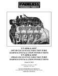
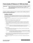
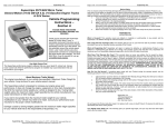
LS-1 Wiring Harness
05/03/2013
INSTRUCTIONS & SUPPLEMENTAL INFORMATION
4L60E Electric Automatic
Street & Performance
#1 Hot Rod Lane ~ Mena, AR 71953
479-394-5711 ~ fax 479-394-7113
email [email protected] ~ www.hotrodlane.cc
LS-1 Harness Installation Instructions
The following instructions are intended as an aid to assist in harness installation. More in depth information can
be obtained by ordering the applicable GM service manual (in three volumes). Troubleshooting techniques and
diagnosis are beyond the scope of these instructions. Diagnostic flow charts and troubleshooting advice are
included in the GM service manual or online at www.hotrodlane.cc under LS TECH.
The general design of the harness allows enough length for computer mounting in the dash & kick panel or
underhood area. Special harness lengths can be provided on a custom order basis.
All harness connections are clearly tagged. If for some reason a tag has been removed, consult the LS-1
Harness layout. Please identify all tags prior to beginning your installation.
The following information will briefly discuss the individual harness connections:
1.
Passenger Side Injectors (4 plugs w/green, blue, yellow, & purple uncommon wires) Lay the harness up over the intake with the passenger side and driver side injector and coil
connectors on each side of the engine. Connect the injector plugs into the fuel injection. The
longest plug to the farthest point and so forth. This will help hold the harness in place.
2.
Driver Side Injectors (4 plugs w/black, red, white & brown uncommon wires) - Repeat the steps
outlined above.
3.
Passenger Coil (4 plugs w/tan waterproof rubber seal w/orange, yellow, gray, & white uncommon
wires) - Connect passenger side coils into injector coil packs.
4.
Driver Coil (4 Plugs w/tan waterproof rubber seal w/purple, blue, green, red uncommon wires) Connect driver side coils into injector coil packs.
5.
Mass Air Flow Plug (MAF) (black connector w/white cap and purple waterproof rubber seal) Located on the air duct, in the front of the intake manifold. If your using the Street & Performance Air
Cleaner w/ZR-1 Air Temp, just plug it into the passenger side back of air cleaner. Take care when handling the MAF. Do not touch the sensing elements or allow anything to come in contact with them. The
PCM converts the mass air flow sensor input signal into grams per second, indicating the amount of air
flow entering the engine.
6.
MAP Sensor Plug (grey plug w/white cap and purple waterproof rubber seal) - The Manifold
Absolute Pressure (MAP) measures the change in the intake manifold pressure from engine load and
speed changes and sends proportional adjustments to the computer. Connect the MAP sensor electronic connector from the harness to the MAP sensor lead at the rear of the intake manifold. The MAP
sensor lead will already be on most new & used engines.
7.
CAM Sensor Plug (black connector w/white cap and purple waterproof rubber seal) - The
camshaft position sensor (CPS) must be installed prior to installing the intake manifold. The camshaft
position sensor is located on the timing cover behind the water pump near the camshaft sprocket. As
the camshaft sprocket turns, a magnet activates the Hall effect switch in the camshaft position sensor.
The plug for harness installation is at the rear of the intake manifold. The CMP Sensor signal is created
as piston #1 is approximately 25 degrees after top dead center (TDC) on the power stroke.
8.
Knock Sensor Plug (black connector w/blue cap and grey waterproof rubber seal) - Two knock
sensors (KS) are used, one for each bank of injectors. Input signals from the knock sensors are used
to detect engine detonation, allowing the PCM to retard Ignition Control (IC) spark timing, based upon
the amplitude and frequency of the KS signal being received. If a knock is detected, the computer will
automatically retard the timing. Connect the knock sensor plug to the plug extending out the rear of the
intake.
9.
Linear EGR Plug (white connector w/lite blue waterproof rubber seal) - Must be in use when running full emissions in 1974 & later vehicles. Some state requirements differ.
(1)
10.
Throttle Position Sensor Plug (black connector w/purple waterproof rubber seal) - Returns a proportional voltage to the computer that relates to the angular position of the throttle plates. A relaxed
throttle-shows low voltage (approx. 8V) and a wide open throttle-shows high voltage (approx 4.5V).
11.
Idle Air Motor Plug (black connector w/blue waterproof rubber seal) - Computer controlled stepper
motor which adjusts engine idle at different loads.
12.
Engine Temp Sensor Plug (black connector w/purple waterproof rubber seal) - Senses engine
coolant temperatures during all operating conditions and signals electric fan operations. Located front
head exhaust port. Must use IROC/TA Coolant Sensor #12551708, 3 prong plug on Vette motors.
13.
Air Temp Sensor Plug (grey connector w/lite blue waterproof rubber seal) - Operates in the same
fashion as the coolant temp sensor, except it relates to the air temp entering the plenum.
14.
Canister Purge Plug (red connector w/blue cap & grey waterproof rubber seal) - Use with emission
vehicles, connects to the EVAP canister vent solenoid.
15.
Crank Sensor Plug -Crankshaft position sensor (CPS) located on passenger side lower rear of engine.
16.
Oil Level Plug (black connector w/blue cap and grey waterproof rubber seal) - For determining low
oil levels in the oil pan. Connects into oil pan. Oil pressure for your gauge must be provided by its
sending unit. The unit can be installed down in block-off plate by filter.
17.
Anti Theft - By-passes computer anti-theft.
18.
Diagnostic Link Plug (ALDL) - Automatic Line Diagnostic Link is used in conjunction with the check
engine light and testing or troubleshooting.
19.
Fuel Pump Relay Plug - Starts and stops fuel pump. During key-on runs 2 seconds to load injectors.
20.
Brake Light Switch Wire (purple) - 12V Ignition normally closed switch. This wire must have 12 volts
all the time, except when you put the brake on. This will take the torque converter out of lock-up. Use
GM switch #255244845
21.
Check Engine Light Wire Ground (brown) - For the use of a check engine light. Any 12V automotive
light will work. It can be mounted as a permanent fixture in the dash, or used as a diagnostic aid only.
The wire is completes the connection to your 12 volt hot wire when the key in in start or run. The brown
wire is the ground for the cuircut.
Tach Wire (if desired) (white) - Feeds pulse to tachometer. If Tach fails to operate on this pulse, contact Abbott Enterprises, 800-643-5973 for alternate pulse signal simulator.
22.
23.
Battery Wire (orange) - Connects to main post on positive side of starter. If you’re using a battery disconnect, this lead must go to the hot side of the disconnect.
24.
Park Neutral Position Wire (orange ) (if desired) - The Park/Neutral Position (PNP) switch indicates to
the PCM when the transmission is in park, neutral, or drive. This information is used for the EGR and
IAC valve operation.
25.
Electric Speedometer Wire (green) - 4000 pulse to cruise or electric speedometer. If you have
Speedo with 8,000 to 16,000 plus you will need a Dakota Digital speed interface SGI-5 which S&P
can provide.
26.
Low Oil Level Wire (white) - For low oil indicator light
27.
Hot Feed Electric Fuel Pump Wire (brown) - Provides 12V to the fuel pump. A fuel pump relay is also
provided with the harness and is energized/de-energized by the ECM.
28.
Ignition Switch Hot Wire (red)- The single ignition wire must be connected to provide 12V with the key
in START (crank) and RUN position. 12V is then distributed through the fuse block to the computer
(ECM), injectors and coil. The fuse block has six (6) 10 amp and one (1) 20 amp fuses. Each injector
bank is fused as is the computer, battery and coil. 1955-64 GM ignition switches will not work unless you
jumper from Ignition 1 to Ignition 2 You need 12volts crank and run
(2)
29.
Engine Ground Wire (black wire w/soldered aluminum grommet) - The ground system is critical for
proper operation. A good battery to motor, and motor to harness ground is essential
Ground Battery to Motor or Trans (a must)!
Ground Motor to Frame and Motor to Body!
Ground Tank to Frame
30.
Vehicle Speed Sensor Plug (VSS) (black connector w/lite blue waterproof rubber seal) - The vehicle speed sensor is a pulse counter type input that informs the PCM how fast the vehicle is being driven.
The VSS system uses an inductive sensor mounted in the tail housing of the transmission and a toothed
reluctor wheel on the tail shaft. As the reluctor rotates, the teeth alternately interfere with the magnetic
field of the sensor creating an induced voltage pulse.
31.
Driver Front O2 Plug - Oxygen Sensor****Go to www.hotrodlane.cc then click on LS TECH then O2
sensor page.
32.
Passenger Front O2 Plug - Oxygen Sensor
33.
Driver Rear O2 Plug - Must be placed after the catalytic converter. If your not running catalytic converters contact Street & Performance for computer reprogramming.
34.
Passenger Rear O2 Plug - Must be placed after catalytic converter. If not running catalytic converters
contact Street & Performance for computer reprogramming.
If your not Doing Full Emission (1974 & earlier) you do not have to run Catalytic Converters and rear O2
Sensors can be turned off when we program it for you.
Street Rod Style Coated Headers
G-body Style Coated Headers
Taylor Custom Color LS-1
Spark Plug Wires.
97-98 Vette Dual Fuel Rails
99-up Single Line
LS-1 Top Covers
LS-1 Polished Water Pump
3.
55-57 HEADERS
LS-1 Vette Fuel Lines
and connectors
LS-1 Camaro Pan Kit
LS-1 Vette Biscuit Motor Mounts
4L60 E Wiring Harness Installation Instructions
Before you begin it is important that you familiarize yourself with the harness. Try and visualize how the harness fits with your
particular application.
Identify the locations of the computer, the fuse panel etc. The more organized you are when you begin the easier the installation
will progress. The Street & Performance Harness is designed to compliment the looks and performance of your engine. Proper
planning will insure your complete satisfaction. Remember Fuel Injection Technology; If you don’t know where it goes
ASK!
1
Lay the harness in the valley
between the intake & heads
under any existing hosing.
2
Connect the injectors being
careful that the disconnect clip
is to the outside of the engine.
4
3
Clip the injectors into place
Place the coils in the same
manner as the injectors.
4
5
Gently push the coil plug into
the connector on the underneath of the coil pack.
7
Lay all the plugs for the front of
the engine connections into
place.
8
6
Plug into MAP sensor lead at rear of intake.
10
11
Install Cam sensor at rear of
intake.
Connect knock sensor plug
into knock sensor lead at rear
of intake
Install throttle position sensor
at front of engine
Install idle speed motor at front
of engine
12
12
12
On Vette remove Coolant Temp sensor and replace with 97-98
IROC/TA. pt#12551708. Part is available from Street & Performance
or G.M. The Coolant Temp Sensor uses a three prong plug. 99-up
coolant sensor part # 12608814
Connect Engine Temp Sensor
plug.
13
Install air temp sensor at rear
of Street & Performance air
cleaner
15
31
13
Connect crank sensor plug
Check the O2 sensor for breaks or chafing. Replace if necessary.
Available from G.M or Street & Performance, part #25312202 A/C
Delco AF 3-108
Install your Oxygen sensor to
the O2 plug
32
Install the O2 sensor into the
front O2 bun on your header
collector.
For non-emission vehicles,
install the rear O2 plugs to the
LS-1 Simulator, this eliminates
the catalytic converter.
Wire tie the installed wires
neatly
Clip excess off of ties
Attached tied wires to the top
cover clip bar
Reinstall the top cover
Install Vat by-pass to Vats plug
in harness.
***Caution!***
Connect the brown fuel pump
wire directly to the fuel pump.
Do not connect thru buss or
panel.
5.
Street Rod Style
Low Driver side Alternator
Low Passenger side A/C
Street Rod Style
Low Driver side Alternator
Low Passenger side A/C
2:00 O’Clock Passenger P/S
50’s & Later
High Driver side Alternator
High Passenger side A/C
Low Driver side P/S
1999 & u Vette ~ IROC ~ T/A ~ Trucks
#09354896/12200411
04 Blue/Green 12586243
Auto VIN # 2G1FP22G9Y2126954
Manual VIN # 2G2FV22G5X2232687
Street Rod Style
Low Driver side Alternator
1997-98 Vette Computer
1998 - IROC/TA
#16238212
Auto VIN # 2G2FV22G5W2206587
Manual VIN # 2G1FP22G9W2124277
Street Rod Style
Low Pass side Alternator
Low Driver side P/S
Street Rod Style
Low Pass side Alternator
Street & Performance LS1/LS6 DVD
CALL ABOUT OUR HOW TO BOOKS
Common Installation Questions;
Q.
Is it important to follow any particular order when installing the harness?
A.
Yes, Starting at the engine intake manifold, installing the injectors and coils helps hold the harness in place while completing your
installation. The order of installation of the non-engine connectors depends upon your application. (Refer to page 3)
Q.
What happens if I have a short?
A.
The system is protected by fuses in fuse block.. You must find the short before proceeding. Never jumper or bypass around the
fuses. This could damage your harness. Use proper diagnosis and repair techniques.
Q.
Where can I purchase the G.M. Service Manual.
A.
Call Helm’s at 800-782-4356. Most local auto parts stores have many Helm’s books. The Street & Performance Video Series is
packed with useful information. Contact your Street & Performance dealer.
Q.
Where can I find professional help with my harness installation?
A.
Your local Street & Performance dealer can normally assist you in the installation. In addition, Street & Performance conducts a fuel
injection school dealing with the latest in Fuel Injection Technology. Periodically, information is also available on our web site to help
in your installation.
Q.
Do you have technical assistance available?
A.
For technical assistance,.call Street & Performance or your local dealer.
Q.
What should I do if I accidently split or chaf a wire?
A.
The G.M. 1998 Service Manual, Second Edition, Volume 3 of 3, provides detailed instructions on repairing damaged flat wires and
HO2S wiring. Sections 8-307 and 8-309.
Q.
If I break a plug or connector, what should I do?
A.
The G.M. 1998 Service Manual, Second Edition, Volume 3 of 3, provides detailed instructions on repairing damaged flat wires and
HO2S wiring. Section 8-310. CONTACT S&P FOR REPLACEMENT PARTS.
Q.
Can you explain voltage?
A.
You must use a 90 amp or larger alternator with fuel injection. YOU MUST HAVE GOOD GROUNDS. Battery to motor or trans,
engine to frame and engine to body.
Q.
Do I need to save my old harness?
A.
No, although its helpful to save the old ends in case of damage to your new harness.
Q.
Where can I find the trouble code references?
A.
Included with your harness or go to www.hotrodlane.cc
LS-1 in a 1998 S-10
LS-1 in a 1998 Crew Cab
LS-1 in a Chevy Suburban
Street & Performance
#1 Hot Rod Lane ~ Mena, AR 71953
501-394-5711 ~ fax 501-394-7113 ~ email [email protected] ~ www.hotrodlane.cc
DTC
P0101
P0102
P0103
P0107
P0108
P0112
P0113
P0117
P0118
P0121
P0122
P0123
P0125
P0131
P0132
P0133
P0134
P0135
P0143
P0144
P0146
P0147
P0151
P0152
P0153
P0154
P0155
P0171
P0172
P0174
P0175
P0201
P0202
P0203
P0204
P0205
P0206
P0300
P0325
P0327
P0332
P0336
P0341
P0401
P0403
P0404
P0405
P0420
P0440
P0442
P0446
P0452
P0453
P0500
P0506
P0507
P0530
P0560
P0601
P0602
P0704
P0705
P0706
P0711
P0712
P0713
ALDL Diagnostic Description
Mass Air Flow System Performance
MAF Sensor Circuit Low Frequency
MAF Sensor Circuit High Frequency
MAP Sensor Circuit Low Voltage
MAP Sensor Circuit High Voltage
IAT Sensor Circuit Low Voltage
IAT Sensor Circuit High Voltage
ECT Sensor Circuit Low Voltage
ECT Sensor Circuit High Voltage
TP Sensor Performance
TP Sensor Circuit Low Voltage
TP Sensor Circuit High Voltage
ECT Excessive Time to Closed Loop
HO2S Circuit Low Voltage Bank 1 Sensor 1
HO2S Circuit High Voltage Bank 1 Sensor 1
HO2S Circuit Slow Response Bank 1 Sensor 1
HO2S CKT Insufficient Activity Bank 1 Sensor 1
HO2S Heater Circuit Bank 1 Sensor 1
HO2S Circuit Low Voltage Bank 1 Sensor 3 (post converter)
HO2S Circuit High Voltage Bank 1 Sensor # (post converter)
HO2S Circuit Insufficient Activity Bank 1 Sensor 3 (post converter)
HO2S Heater Circuit Bank 1 Sensor 3 (post converter)
HO2S Circuit Low Voltage Bank 2 Sensor 1
HO2S Circuit High Voltage Bank 2 Sensor 1
HO2S Circuit Slow Response Bank 2 Sensor 1
HO2S Circuit Insufficient Activity Bank 2 Sensor 1
HO2S Heater Circuit Bank 2 Sensor 1
Fuel Trim System Lean Bank 1
Fuel Trim System Rich Bank 1
Fuel Trim System Lean Bank 2
Fuel Trim System Rich Bank 2
Injector 1 Control Circuit
Injector 2 Control Circuit
Injector 3 Control Circuit
Injector 4 Control Circuit
Injector 5 Control Circuit
Injector 6 Control Circuit
Engine Misfire Detected
Knock Sensor System
Knock Sensor Circuit Bank 1
Knock Sensor Circuit Bank 2
18x Reference Signal Circuit
CMP Sensor Circuit Performance
EGR System Flow Insufficient
EGR Solenoid Control Circuit
EGR System Performance
EGR Pintle Position Circuit Low Voltage
TWC System Low Efficiency
EVAP System
EVAP Control System Small Leak Detected
EVAP Canister Vent Blocked
Fuel Tank Pressure Sensor Circuit Low Voltage
Fuel Tank Pressure Sensor Circuit High Voltage
Vehicle Speed Sensor Circuit
Idle Control System Low RPM
Idle Control System High RPM
A/C Refrigerant Pressure Sensor Circuit
System Voltage
PCM Memory
PCM Not Programmed
Clutch Anticipate Switch Circuit
Trans Range Switch Circuit
Trans Range Switch Performance
Transaxle Fluid Temperature (TFT) Sensor Circuit Performance
Refer to 4:60-E Automatic Transmission Diagnosis
Transaxle Fluid Temperature (TFT) Sensor Circuit - Low Signal
Refer to 4:60-E Automatic Transmission Diagnosis
Transaxle Fluid Temperature (TFT) Sensor Circuit Performance
Refer to 4:60-E Automatic Transmission Diagnosis
Domestic
A
A
A
B
B
B
B
B
B
A
A
A
A
B
B
B
B
B
B
B
B
B
B
B
B
B
B
B
B
B
B
B
B
B
B
B
B
B
D
D
D
B
B
A
B
B
B
A
A
A
A
B
B
B
B
B
D
D
B
B
D
D
D
D
Illuminate MIL
Yes
Yes
Yes
Yes
Yes
Yes
Yes
Yes
Yes
Yes
Yes
Yes
Yes
Yes
Yes
Yes
Yes
Yes
Yes
Yes
Yes
Yes
Yes
Yes
Yes
Yes
Yes
Yes
Yes
Yes
Yes
Yes
Yes
Yes
Yes
Yes
Yes
Yes
Yes
No
No
Yes
Yes
Yes
Yes
Yes
Yes
Yes
Yes
Yes
Yes
Yes
Yes
Yes
Yes
Yes
No
No
Yes
Yes
No
No
No
No
D
No
D
No
P0713
P0716
P7017
P0719
P0724
P0730
P0741
P0742
P0748
P0751
P0753
P0756
P0758
P1106
P1107
P1111
P1112
P1114
P1115
P1121
P1122
P1133
P1134
P1153
P1154
P1336
P1351
P1352
P1361
P1362
P1374
P1380
P1381
P1404
P1441
P1554
P1626
P1629
P1635
P1639
P1641
P1651
P1652
P1653
P1662
P1663
P1665
P1671
P1672
P1676
P1810
P1811
P1860
P1887
Transaxle Fluid Temperature (TFT) Sensor Circuit - High Signal
Refer to 4L60E Automatic Transmission Diagnosis
Automatic Transmission Input (Shaft) Speed Sensor Circuit Performance
Refer to 4L60E Automatic Transmission Diagnosis
Automatic Transmission Input (Shaft) Speed Sensor No Input
Refer to 4L60E Automatic Transmission Diagnosis
Brake Switch Circuit Low
Refer to 4L60E Automatic Transmission Diagnosis
Brake Switch Circuit High
Refer to 4L60E Automatic Transmission Diagnosis
Incorrect Gear Ratio - Refer to 4L60E Automatic Transmission Diagnosis
Torque converter Clutch System Stuck Off
Refer to 4L60E Automatic Transmission Diagnosis
Torque Converter Clutch System Stuck On
Refer to 4L60E Automatic Transmission Diagnosis
Pressure Control Solenoid Valve Circuit Malfunction
Refer to 4L60E Automatic Transmission Diagnosis
Shift Solenoid 1 - Performance/Stuck Off
Refer to 4L60E Automatic Transmission Diagnosis
Shift Solenoid 1 - Electrical
Refer to 4L60E Automatic Transmission Diagnosis
Shift Solenoid 2 - Performance/Stuck On
Refer to 4L60E Automatic Transmission Diagnosis
Shift Solenoid 2 - Electrical
Refer to 4L60E Automatic Transmission Diagnosis
MAP Sensor CKT Intermittent High Voltage
MAP Sensor CKT Intermittent Low Voltage
IAT Sensor CKT Intermittent High Voltage
IAT Sensor KCKT Intermittent Low Voltage
ECT Sensor CKT Intermittent Low Voltage
ECT Sensor CKT Intermittent High Voltage
TP Sensor CKT Intermittent High Voltage
TP Sensor CKT Intermittent Low Voltage
HO2S Insufficient Switching Bank 1 Sensor 1
HO2S Transition Time Ratio Bank 1 Sensor 1
HO2S Insufficient Switching Bank 2 Sensor 1
HO2S Transition Time Ratio Bank 2 Sensor 1
CKP System Variation Not Learned
IC Circuit Open
Bypass Circuit Open
IC Circuit Not Toggling
Bypass Circuit Shorted
3X Reference Circuit
EBCM DTC Rough Data Unstable
Misfire Detected No EBCM/PCM Serial Data
EGR Valve Closed Pintle Position
EVAP System Flow During Non-Purge
Cruise Control Status Circuit
Theft Deterrent System Fuel Enable CKT
Theft Deterrent Crank Signal Malfunction
5 Volt Reference (A) Circuit
5 Volt Reference (B) Circuit
A/C Relay Control Circuit
Fan 1 Relay Control Circuit
Fan 2 & 3 Relay Control Circuit
Fuel Level Output Control Circuit
Cruise Control Inhibit Control Circuit
Generator Lamp Control Circuit
EVAP Vent Solenoid Control Circuit
MIL Control Circuit
Low Engine Oil Level Lamp Control Circuit
EVAP Canister Purge Solenoid Control CKT
Auto Transmission Fluid Pressure Manual Valve Position Switch Malfunct
Refer to 4L60E Automatic Transmission Diagnosis
Maximum Adapt and Long Shift
Refer to 4L60E Automatic Transmission Diagnosis
Torque Converter Clutch PWM Solenoid Circuit
Refer to 4L60E Automatic Transmission Diagnosis
TCC Release Switch Malfunction
Refer to 4L60E Automatic Transmission Diagnosis
D
No
B
Yes
B
Yes
D
No
D
No
D
B
No
Yes
A
Yes
D
Yes
B
Yes
A
Yes
A
Yes
A
Yes
D
D
D
D
D
D
D
D
B
B
B
B
A
B
B
B
B
B
D
D
B
B
D
D
D
B
B
D
B
B
D
D
D
B
D
D
B
B
No
No
No
No
No
No
No
No
Yes
Yes
Yes
Yes
Yes
Yes
Yes
Yes
Yes
Yes
No
No
Yes
Yes
No
No
No
Yes
yes
No
Yes
Yes
No
No
No
Yes
No
No
Yes
Yes
D
No
A
Yes
B
Yes
LS-1 Wiring Harness
S&P adds an extra Blue Wire for
Aftermarket Oil Pressure Gauge & a
Green Wire for Aftermarket Coolant
Temp.
28. To Ignition Hot w/key Start (red)
23. Battery (orange)
17. VATs
Fuse Panel
19. Fuel Pump Relay
26. Low Oil Level (white)
25. Elec Speedometer (grn)
Red Plug
24. Park Neutral (Orange)
13. Air Temp Sensor
20. Brake Light (purple
brown & black wires
5. Mass Air Flow
yellow, black & red wires
21. Check Engine Light (brown)
12. Engine Temp Sensor
35. Coolant Temp (grn)
blue, green & yellow wires
22. Tach (white)
11. Idle Air Motor
Blue Plug
yellow, brown, red & white wires
14. EVAP
Canister Purge
10. Throttle Position Sensor
blue, brown, light gray wires
4. Driver Coil
purple, blue, green, red uncommon wires
2. Driver Injector
18. ALDL Diagnostic Link
w/black, red, white & brown uncommon wires
32. Pass Front O2
purple, black, red & brown wires
33. Driver Rear O2
purple, red, brown, & black wires
34. Passenger Rear O2
purple, red, brown, black
30. Vehicle Speed Sensor
twisted yellow & purple wires
31. Driver Front O2
8. Knock Sensor
blue & blue wires
purple, red, black & brown wires
7. CAM Sensor
red, black, brown wires
16. Oil Level
6. MAP Sensor
black & brown wires
gray, green & black wires
15. Crank Sensor
yellow, black, red wires
Transmission
29. Engine Ground
27. Hot Feed Electric
Fuel Pump (brown)
9. Linear EGR
blue, brown, black, gray, gray
1. Passenger Injector
w/green, blue, yellow & purple uncommon wires
17. To Vats
3. Passenger Coil
w/orange, yellow, gray, & white uncommon wires
#1 Hot Rod Lane
Mena, Arkansas 71953
Ph. 479-394-5711 Fax. 479-394-7113
www.hotrodlane.cc
If you have a 2 prong pressure brake switch, you will need this
brake switch relay kit.
Hook to red brake wire
12 Volts ALL THE TIME
with brake OFF.
NO VOLTAGE WITH BRAKE
ON!
For brake light
12 Volts with brake on ONLY
12 Volts In
12 Volts In
GM Brake Switch #25524845
AC Delco #D850A
A. Throttle Body ~T.P.I ~'92-'93 LT1 (One Wire)GM# 25166816 AC DELCO# AFS21
B. Throttle Body ~T.P.I ~'92-'93 LT1 (Three Wire)GM# 25176708 AC DELCO# 213-632
B2. S&P Pig Tail to convert from One Wire System to a Heated Three Wire System
C. '94-'96 LT1 Vette~ '94-'96 BUICK, CAD., '94-'97 IROC/TA (Four Wire) O2 Sensor
GM# 25312184 AC DELCO# AFS-75 C. is also used for '97-'04 LS1 Factory Corvette Engines - S&P
LS1 Harness uses IROC O2 Sensor (D)
D. '98- '02 LS1 IROC/TA Engines GM# 25312197 AC DELCO# AFS98
E. '05 LS2 with Square Plug GM#12587785 AC DELCO# 213-1702
37 DEGREE FITTINGS AVAILABLE
FOR CONVERTING TO STAINLESS
STEEL TRANSMISSION LINES. SEE
WEB FOR CUSTOM SET OF STAINLESS STEEL TRANSMISSION COOLER LINES.
www.hotrodlane.cc
479-394-5711