1
Table of Contents
Introduction
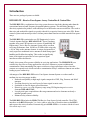
DXE-RFS-2P Receive Four Square Array Controller and Switch Package
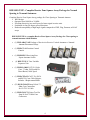
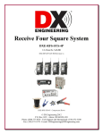
DXE-RFS-TS2P Complete Receive Four Square Array Package
System Overview
Features
Prerequisite
Additional Parts Required, Not Supplied
Example of Array Performance
Site Selection
Proximity to Transmitting Antennas
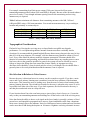
Topographical Considerations
Site Selection in Relation to Noise Sources
Ground System
Lightning Protection
Sizing the Array
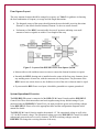
Four Square Layout
System Operational Overview
Installation
Active Antenna Elements
Station Feedline, Active Antenna Feedline and Delay Lines
Active Antenna Feedlines
Delay Lines
Control and Power Connections
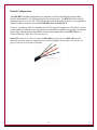
Default Configuration
Alternate Configurations
Supplying Power Using the Feedline
Directional Control Using the Feedline
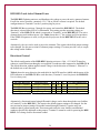
DXE-RFS-2 and Active Element Power
Directional Control
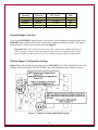
Internal Jumper Selection
Default Jumper Configuration Settings
Powering Through the Feedline
Directional Control Using the Feedline
Optimizing the Array
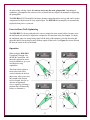
Front-to-Rear (Null) Optimizing
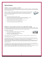
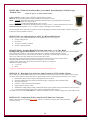
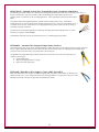
Optional Items
Technical Support and Warranty
3
3
4
5
5
6
6
7
9
9
10
10
11
11
12
13
13
14
14
15
16
16
18
19
21
21
21
24
24
25
25
26
26
26
27
28
32
Figures, Tables, and Diagrams
Azimuth Patterns for an Optimized 40 meter Array
Figure 1 - Site Selection Clear Distance
Table 1 - Array 1500 Watt ERP Safety Distance
Table 2 - Array Side Lengths
Figure 2 - Layout of the DXE-RFS-TS2P Four Square System
Figure 3 - Active Element L1MF Jumper Locations
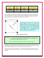
Table 3 - Examples of DLY3 Required Length
Figure 4 - Diagonal Dimensions
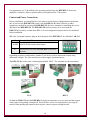
CC-8 and RFS Connectors
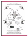
DXE-RFS-TS2P Default Connection Diagram Using Factory Jumper Settings
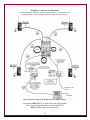
Diagram 2 - Alternate Configuration
Diagram 3 - Alternate Configuration
Table 4 - BCD Directional Control Matrix
Table 5 - Differential Voltage Control Matrix
Figure 5 - Jumper Locations and Default Settings
Operation Pattern Diagram
8
9
10
12
13
15
17
17
18
20
22
23
24
25
25
27
2