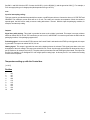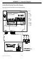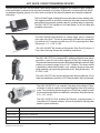
1
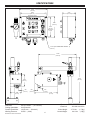
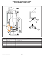
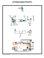
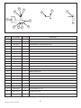
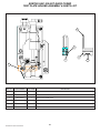
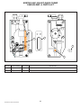
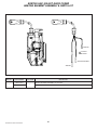
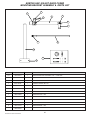
STENCILING & MARKING
SYSTEMS
OWNER’S MANUAL
KORTHO
HOT QUICK CODER
INSTALLATION - OPERATION - MAINTENANCE
MODEL SHOWN: HQC-100
MODEL SHOWN: HQC-100
WITH HOT QUICK CODER BENCH MOUNT STAND - 12” X 18”
UNIVERSAL STENCILING & MARKING SYSTEMS, INC.
P.O. BOX 871 - ST. PETERSBURG, FLORIDA 33731 USA
PH: (727) 894-3027 FAX: (727) 821-7944
E-Mail: [email protected] Website: www.universal-marking.com
KORTHO Hot Quick Coder Manual
HQC-08101
1
TABLE OF CONTENTS
Preface
Specifications
HQC-100
1.
General Instructions Before Use
Liability
Life Span
Normal Use
Environment
Operational Personnel
2.
General Introduction
The Hot Quick Coder
The Control Box
The Control Panel
Connections on the Control Box
The Support Arm
3.
Safe Use
Safety Measures
General Safety Measures
Explanation of attached Stickers
4.
Installation Of The Hot Quick Coder
Assembly instructions
Connection instructions
5.
Putting The Hot Quick Coder Into Operation
Setting up the Control Box
Applying the Text material
Adjusting the Position of the Hot Quick Coder
6.
Starting Up The Hot Quick coder
Preparation for use
Adjustment of the Hot Quick Coder
7.
The Hot Quick Coder During Use
Changing a Text Head
Replacing the Ink Roll
8.
Deactivating The Hot Quick Coder
Stopping printing for a short time
Stopping printing for a longer time
9.
Maintenance And Cleaning
Maintenance
Cleaning
Appendix A - List of possible Malfunctions
Making a Diagnosis of Malfunctions
Locating faults in the Hot Quick Coder Electronics System
Checkpoint 1 - 4
Checkpoint 5 - 7
Checkpoint 8
Checkpoint Checklist: Steps to be carried out
Print Quality Problems
Appendix B - Technical Data
Technical Data Hot Quick Coder
Technical Data Control Box for the Hot Quick Coder
Temperature setting up with the Control Box
Appendix C - Connection Diagrams
Control Box Electrical Connection Diagram
Signal Device: Checking Wiring Connection
Setting the Hot Quick Coder to the correct mains voltage (110/220V)
Parts Lists, & Diagrams
2
KORTHO Hot Quick Coder Manual
○
○
○
○
○
○
○
○
○
○
○
○
○
○
○
○
○
○
○
○
○
○
○
○
○
○
○
○
○
○
○
○
○
○
○
○
○
○
○
○
○
○
○
○
○
○
○
○
○
○
○
○
○
○
○
○
○
○
○
○
○
○
○
○
○
○
○
○
○
○
○
○
○
○
○
○
○
○
○
○
○
○
○
○
○
○
○
○
○
○
○
○
○
3
○
○
○
○
○
○
○
○
○
○
○
○
○
○
4
○
○
○
○
○
○
○
○
○
○
○
○
○
○
○
○
○
○
○
○
○
○
○
○
○
○
○
○
○
○
○
○
○
○
○
○
○
○
○
○
○
○
○
○
○
○
○
○
○
○
○
○
○
○
○
○
○
○
○
○
○
○
○
○
○
○
○
○
○
○
○
○
○
○
○
○
○
○
○
○
○
○
○
○
○
○
○
○
○
○
○
○
○
○
○
○
○
○
○
○
○
○
○
○
○
○
○
○
○
○
○
○
○
○
○
○
○
○
○
○
○
○
○
○
○
○
○
○
○
○
○
○
○
○
○
○
○
○
○
○
○
○
○
○
○
○
○
○
○
○
○
○
○
○
○
○
○
○
○
○
○
○
○
○
○
○
○
○
○
○
○
○
○
○
○
○
○
○
○
○
○
○
○
○
○
○
○
○
○
○
○
○
○
○
○
○
○
○
○
○
○
○
○
○
○
○
○
○
○
○
○
○
○
○
○
○
○
○
○
○
○
○
○
○
○
○
○
○
○
○
○
○
○
○
○
○
○
○
○
○
○
○
○
○
○
○
○
○
○
○
○
○
○
○
○
○
○
○
○
○
○
○
○
○
○
○
○
○
○
○
○
○
○
○
○
○
○
○
○
○
○
○
○
○
○
○
○
○
○
○
○
○
○
○
○
○
○
○
○
○
○
○
○
○
○
○
○
○
○
○
○
○
○
○
○
○
○
○
○
○
○
○
○
○
○
○
○
○
○
○
○
○
○
○
○
○
○
○
○
○
○
○
○
○
○
○
○
○
○
○
○
○
○
○
○
○
○
○
○
○
○
○
○
○
○
○
○
○
○
○
○
○
○
○
○
○
○
○
○
○
○
○
○
○
○
○
○
○
○
○
○
○
○
○
○
○
○
○
○
○
○
○
○
○
○
○
○
○
○
○
○
○
○
○
○
○
○
○
○
○
○
○
○
○
○
○
○
○
○
○
○
○
○
○
○
○
○
○
○
○
○
○
○
○
○
○
○
○
○
○
○
○
○
○
○
○
○
○
○
○
○
○
○
○
○
○
○
○
○
○
○
○
○
○
○
○
○
○
○
○
○
○
○
○
○
○
○
○
○
○
○
○
○
○
○
○
○
○
○
○
○
○
○
○
○
○
○
○
○
○
○
○
○
○
○
○
○
○
○
○
○
○
○
○
○
○
○
○
○
○
○
○
○
○
○
○
○
○
○
○
○
○
○
○
○
○
○
○
○
○
○
○
○
○
○
○
○
○
○
○
○
○
○
○
○
○
○
○
○
○
○
○
○
○
○
○
○
○
○
○
○
○
○
○
○
○
○
○
○
○
○
○
○
○
○
○
○
○
○
○
○
○
○
○
○
○
○
○
○
○
○
○
○
○
○
○
○
○
○
○
○
○
○
○
○
○
○
○
○
○
○
○
○
○
○
○
○
○
○
○
○
○
○
○
○
○
○
○
○
○
○
○
○
○
○
○
○
○
○
○
○
○
○
○
○
○
○
○
○
○
○
○
○
○
○
○
○
○
○
○
○
○
○
○
○
○
○
○
○
○
○
○
○
○
○
○
○
○
○
○
○
○
○
○
○
○
○
○
○
○
○
○
○
○
○
○
○
○
○
○
○
○
○
○
○
○
○
○
○
○
○
○
○
○
○
○
○
○
○
○
○
○
○
○
○
○
○
○
○
○
○
○
○
○
○
○
○
○
○
○
○
○
○
○
○
○
○
○
○
○
○
○
○
○
○
○
○
○
○
○
○
○
○
○
○
○
○
○
○
○
○
○
○
○
○
○
○
○
○
○
○
○
○
○
○
○
○
○
○
○
○
○
○
○
○
○
○
○
○
○
○
○
○
○
○
○
○
○
○
○
○
○
○
○
○
○
○
○
○
○
○
○
○
○
○
○
○
○
○
○
○
○
○
○
○
○
○
○
○
○
○
○
○
○
○
○
○
○
○
○
○
○
○
○
○
○
○
○
○
○
○
○
○
○
○
○
○
○
○
○
○
○
○
○
○
○
○
○
○
○
○
○
○
○
○
○
○
○
○
○
○
○
○
○
○
○
○
○
○
○
○
○
○
○
○
○
○
○
○
○
○
○
○
○
○
○
○
○
○
○
○
○
○
○
○
○
○
○
○
○
○
○
○
○
○
○
○
○
○
○
○
○
○
○
○
○
○
○
○
○
○
○
○
○
○
○
○
○
○
○
○
○
○
○
○
○
○
○
○
○
○
○
○
○
○
○
○
○
○
○
○
○
○
○
○
○
○
○
○
○
○
○
○
○
○
○
○
○
○
○
○
○
○
○
○
○
○
○
○
○
○
○
○
○
○
○
○
○
○
○
○
○
○
○
○
○
○
○
○
○
○
○
○
○
○
○
○
○
○
○
○
○
○
○
○
○
○
○
○
○
○
○
○
○
○
○
○
○
○
○
○
○
○
○
○
○
○
○
○
○
○
○
○
○
○
○
○
○
○
○
○
○
○
○
○
○
○
○
○
○
○
○
○
○
○
○
○
○
○
○
○
○
○
○
○
○
○
○
○
○
○
○
○
○
○
○
○
○
○
○
○
○
○
○
○
○
○
○
○
○
○
○
○
○
○
○
○
○
○
○
○
○
○
○
○
○
○
○
○
○
○
○
○
○
○
○
○
○
○
○
○
○
○
○
○
○
○
○
○
○
○
○
○
○
○
○
○
○
○
○
○
○
○
○
○
○
○
○
○
○
○
○
○
○
○
○
○
○
○
○
○
○
○
○
○
○
○
○
○
○
○
○
○
○
○
○
○
○
○
○
○
○
○
○
○
○
○
○
○
○
○
○
○
○
○
○
○
○
○
○
○
○
○
○
○
○
○
○
○
○
○
○
○
○
○
○
○
○
○
○
○
○
○
○
○
○
○
○
○
○
○
○
○
○
○
○
○
○
○
○
○
○
○
○
○
○
○
○
○
○
○
○
○
○
○
○
○
○
○
○
○
○
○
○
○
○
○
○
○
○
○
○
○
○
○
○
○
○
○
○
○
○
○
○
○
○
○
○
○
○
○
○
○
○
○
○
○
○
○
○
○
○
○
○
○
○
○
○
○
○
○
○
○
○
○
○
○
○
○
○
○
○
○
○
○
○
○
○
○
○
○
○
○
○
○
○
○
○
○
○
○
○
○
○
○
○
○
○
○
○
○
○
○
○
○
○
○
○
○
○
○
○
○
○
○
○
○
○
○
○
○
○
○
○
○
○
○
○
○
○
○
○
○
○
○
○
○
○
○
○
○
○
○
○
○
○
○
○
○
○
○
○
○
○
○
○
○
○
○
○
○
○
○
○
○
○
○
○
○
○
○
○
○
○
○
○
○
○
○
○
○
○
○
○
○
○
○
○
○
○
○
○
○
○
○
○
○
○
○
○
○
○
○
○
○
○
○
○
○
○
○
○
○
○
○
○
○
○
○
○
○
○
○
○
○
○
○
○
○
○
○
○
○
○
○
○
○
○
○
○
○
○
○
○
○
○
○
○
○
○
○
○
○
○
○
○
○
○
○
○
○
○
○
○
○
○
○
○
○
○
○
○
○
○
○
○
○
○
○
○
○
○
○
○
○
○
○
○
○
○
○
○
○
○
○
○
○
○
○
○
○
○
○
○
○
○
○
○
○
○
○
○
○
○
○
○
○
○
○
○
○
○
○
○
○
○
○
○
○
○
○
○
○
○
○
○
○
○
○
○
○
○
○
○
○
○
○
○
○
○
○
○
○
○
○
○
○
○
○
○
○
○
○
○
○
○
○
○
○
○
○
○
○
○
○
○
○
○
○
○
○
○
○
○
○
○
○
○
○
○
○
○
○
○
○
○
○
○
○
○
○
○
○
○
○
○
○
○
○
○
○
○
○
○
○
○
○
○
○
○
○
○
○
○
○
○
○
○
○
○
○
○
○
5
5
5
5
5
6
6
7
8
8
9
9
10
11
11
12
13
13
14
15
16
16
17
17
18
18
19
20
20
21
22
22
23
25
25
26
27
28
28
29
PREFACE
The Kortho Hot Quick Coder can be used on almost any material and surface. Whether you make 10,000 or
100,000 prints a day, the Kortho Hot Quick Coder offers the perfect solution for a variety of coding applications.
The unit accommodates up to three lines of text in a maximum printing area of 12 x 24 mm. The unique springloaded jumping head, with its “butterfly touch”, allows you to make perfect prints on moving products.
The Kortho Hot Quick Coder utilizes hot ink technology to provide clean, sharp, nearly instant dry impressions at
a high rate of speed. Ink rolls, which are dry to the touch at room temperature, are preheated prior to use in the
self-contained heating system. When hot, the ink in the roll becomes fluid and is then ready for operation. During
production, a spare roll can be stored in the unit’s preheat chamber to keep it ready for immediate use. Ink rolls
are available in black, white, red, yellow, green & blue and are supplied in convenient six-pack boxes.
CODER SPECIFICATIONS
The specification section includes a drawing of the Hot Quick Coder with the basic dimensions, the net weight,
print area, max printing & product speed, electrical specifications & working pressure.
KORTHO Hot Quick Coder Manual
3
SPECIFICATIONS
KORTHO HQC-100 HOT QUICK CODER
8.63”
(219 mm)
8.04”
4.21”
(204 mm)
(107 mm)
(MOUNTING HOLES)
6.50”
(165 mm)
5.97”
(152 mm)
(MOUNTING
HOLES)
0.175” (DIA. MOUNTING HOLES - 4)
(4.45 mm)
11.83”
(300 mm)
13.87”
3.64”
(352 mm)
(92 mm)
3.58”
.95”
.99”
.50”
(24 mm)
(25 mm)
(6.4 mm)
7.28”
(6.4 mm)
(91 mm)
Print Area:
Printing Speed Max:
Product Speed Max:
Working Pressure:
KORTHO Hot Quick Coder Manual
0.472” X 0.945” - (12 x 24 mm)
300 Prints/min.
196 Ft./min. - (60m/min.)
56 PSI - (4 bar)
Electrical:
Electrical:
Coder Weight:
Control Weight:
4
110-130 VAC/1 A.
220-240 VAC/0.5 A.
3.75 Lbs. - (1.7 Kg,)
4.41 Lbs. - (2 Kg.)
1 - GENERAL INSTRUCTIONS BEFORE USE
The KORTHO, Hot Quick Coder was manufactured to exacting standards and every available step has been taken to assure
your complete satisfaction. It is most important, however, that the instructions contained in this manual are read and carefully
followed for best results. Failure to do so may result in unsatisfactory performance, damage to the equipment and personal
injury. Read through this user’s manual carefully before putting the Hot Quick Coder into use for the first time. Follow the order
indicated precisely when carrying out any of the actions described in this manual.
Pay particular attention to all stated warnings!
1.1
Liability
KORTHO accepts no liability for damage resulting from the improper or uninformed use of the equipment or caused by
maintenance or other work being carried out improperly. They also accept no liability for the normal wear-and-tear of the
product.
1.2
Life Span
The life span of the equipment is ten years with normal use and compliance with the indicated maintenance periods. The life
span can be negatively influenced if original parts are not used for repairs. All claims to a guarantee or compensation for
damages do not apply in such an instance. The Hot Quick Coder does not contain any harmful substances or materials and
can be scrapped or recycled at the end of its life span. The Ink Rolls should be treated as small chemical waste.
N.B. The above statement is based on the legislation in force as at mid 1995.
1.3
Normal use
Normal use means use under normal conditions i.e. stamping pressure, time and temperature set within the margins indicated
in this User Manual.
1.4
Environment
The environment in which the Hot Quick Coder may be installed must comply with a number of requirements relating to
humidity, temperature and vibrations.
The relative humidity should be between 0 and 85% (non-condensing).
The ambient temperature should be between 41 and 104°F.
The Hot Quick Coder may not be used in any areas having a fire or explosion hazard.
The Hot Quick Coder should be installed in a low vibration location.
1.5
Operational Personnel
Operating personnel are required to be informed by means of instruction as to the functioning of the equipment. They also
need to be informed about the tips and warnings stated in this manual. A specific preliminary training is not required.
Personnel carrying out repairs and technical maintenance on the equipment should have a secondary technical education or
a comparable technical level of knowledge through practical experience.
KORTHO Hot Quick Coder Manual
5
2 - GENERAL INTRODUCTION
The Hot Quick Coder (henceforth HQC) has been developed to apply small texts of one to three lines (max. line length 25 mm)
on a production line. The applications vary from loose products to a continuous product (e.g. packaging film).
The text can be applied to a stationary or a moving product. The maximum permitted product speed is 195 Feet/min. approx.
250 impressions per minute can be produced.
! WARNING:
After using the HQC, it cannot simply be deactivated. For the correct procedure read section 8 “Deactivating the Hot Quick
Coder”
2.1
The Hot Quick Coder
Figure 1: The Hot Quick Coder
The code to be printed is applied to an exchangeable text
head via text characters or blocks. The text head is inked
with a Ink Roll which only delivers the inked (wax-based) at
high temperature. The Ink Roll is kept at temperature in the
heating ring of the HQC.
1 Preheating
2 Ink Roll
3 Text head
2.2
The Control box
A good print quality is achieved with a correct combination of stamping time, stamping pressure, temperature of the text head
and the setting of any counter-pressure plate.
Figure 2: The Control box
1
2
3
4
5
Pressure setting
OFF button
ON button
Temperature setting
Pulse/time setting
6 Print/delay setting
7 HQC air connection
8 Main power connection
9 Hot Quick Coder connection
10 Coupling nut
The stamping time and temperature are set with the buttons on the
Control box. The stamping pressure is set as standard to 56 psi. The
impression can be optimised using a counter-pressure plate, if there is
one. (In case film belts)
!!! NOTE !!!
The HQC air connection is a rapid
connection as indicated in figure 2. Other
figures of the Control box in this manual
still show the old connection.
KORTHO Hot Quick Coder Manual
6
The Control box contains a Control Panel with which specific functions can be performed such as switching the HQC on and
off and setting the print parameters. The Control Panel can also be used to issue a test print signal.
2.2.1 The Control Panel
The Control Panel of the Control box contains the following buttons (see figure 3).
Figure 3: The Control Panel
1
2
3
4
5
6
7
8
9
10
11
OFF button
ON button
TEST button
START button
STOP button
Function button F1, F2
Text head IN
Text head OUT
Temperature adjustment
Pulse/time adjustment
Print/delay adjustment
OFF
(1)
This button is used to switch off the system. The main power remains connected to the system.
ON
(2)
If it is connected to the main power, this button is used to switch the system on. The two green lights indicate
that the two low voltages for the electronics and the magnetic valve are present.
TEST
(3)
The HQC performs a test print. The system should first be enabled by activating the START button.
START
(4)
Once this button is pressed, the HQC is enabled for coding. The green light on the START button is illuminated
when a print signal is received from the signal emitter. This may be a switch, photocell, relay contact, inductive
sensor or 24V DC voltage pulse. The orange light on the STOP button goes out once the START button has
been pressed.
STOP
(5)
Once this button is pressed, the HQC stops coding. The orange light on this button will illuminate to
indicate that the system is in preheating mode. The control will keep the text head at temperature.
F1..F2
(6)
As standard these buttons do not have a function. A specific function may be assigned to them if customer
geared options are incorporated.
HEAD IN
(7)
If the text head holder is in the outermost position, pressing this button moves the text head into the HQC.
KORTHO Hot Quick Coder Manual
7
HEAD OUT
(8)
This button moves the text head holder to the outermost position. This button should be pressed to
change a text head or text. It can then be used to fix the HQC to the material to be coded. The text
head (holder) is moved back into the HQC by pressing (7) HEAD IN.
TEMP
(9)
For adjusting the temperature of the text head between 176°F and 320°F. When the red light is
illuminated continuously once the system has been started up, the text head is heating up. When the
text head has reached the desired temperature, the red light will flash to indicate that the text head is
being kept at temperature. The text head is now kept at the set temperature.
PULSE/TIME
(10)
For adjusting the desired stamping time of the text head. This time can be set between 10 and 50
milliseconds. The orange PULSE/TIME light emits a light signal during the stamping time.
PRINT DELAY
(11)
The green light on this dial is illuminated when a print signal is emitted by the signal emitter.
The print delay can be deactivated by connecting jumper J16 on the PCB in the lid of the Control box. See Appendix C.
2.2.1 Connections on the Control box
The Control box (see figure 2) has an HQC air connection (7), main power connection (8), HQC connection (9) and a swivel
acting as a feed for a signal emitter (10).
2.3
The support arm
Figure 4: The support arm
1 Support arm
2 Counter-pressure plate
The support arm is used to position the HQC and any counter-pressure plate in relation to the product to be printed.
The support arm is suitable for moving the HQC to any position.
The exceptionally short stamping time makes it possible to print directly onto a moving product without further modifications.
KORTHO Hot Quick Coder Manual
8
3 - SAFE USE
The HQC is a durable and reliable piece of coding equipment. In order to work with it safely, it is important that the precautions
indicated in this manual are strictly followed.
SAFETY MEASURES
!
!
!
!
3.1
Before opening the Hot Quick Coder, disconnect it from the main power by removing the power cord from the control
box (see Figure 5).
After using the HQC, it cannot simply be deactivated. For the correct procedure read section 8 “Deactivating the
HQC”.
Take care not to touch the hot text head of Ink Roll (for example when inserting or replacing a Ink Roll). Allow the
printer to cool down for approximately fifteen minutes before carrying out work on the HQC.
Never insert your fingers between the text head and the counter-pressure plate or the product.
General Safety Measures
Figure 5: Disconnecting the Hot Quick Coder from the main
The operation of the HQC is based on:
•
movement (of the text head);
•
pressure (built up between the text head and the counter-pressure plate or the product);
•
heating (of the text head and the Ink Roll).
There are potential dangers hidden in the above with regard to the Hot Quick Coder. Safety measures are given in this manual
for situations which are potentially dangerous. The following is an overview of the most important safety measures.
KORTHO Hot Quick Coder Manual
9
3.2
Explanation of attached stickers
Figure 6: Symbols
Various warning symbols are attached to the Hot Quick Coder.
Here is an explanation of the symbols on the stickers.
General danger
Coding unit remains hot
for awhile after use
KORTHO Hot Quick Coder Manual
Danger due to
high temperature
Maximum adjustable
pressure
10
Danger due to
high voltage parts
Voltage requirements
4 - INSTALLATION OF THE HOT QUICK CODER
4.1
Assembly instructions
Figure 7a: Options for coding products
Figure 7b: Options for coding lengths of film
See Figure 7 for a summary of the options. During assembly ensure that sufficient space is left around the coder to replace
the Ink Roll and to change the text head. If necessary, set up the coder so that it revolves. The dimensional sketches are
included in Appendix D.
1.
2.
3.
4.
5.
6.
7.
Mark the desired position of the holes for assembling the support (2.75” C-C). When determining the position, take
account of the fact that the text head (in the marked position) should ultimately be located approx. 5/64” - 1/8” from the
product surface to be printed (figure 7b).
Drill the mounting holes for the support (diameter 17/64”).
Assemble the support with 1/4” bolts (x2).
Fix the coder to the support.
Mark the desired position of the holes for assembling the Control box.
Drill the mounting holes for the Control box (3/16” diameter).
Assemble the Control box with #8 Screws and nuts (x4).
4.2
Connection instructions
! WARNINGS:
Before opening the control of the Hot Quick Coder, it should first be disconnected from the power. This is done by removing
the main power cable from the Control box (see figure 5).
Only a GROUNDED cable may be used for connecting the equipment
1.
2.
3.
4.
5.
6.
7.
Disconnect the printer from the voltage by removing the main power cable from the Control Box.
Open the Control box.
Check that the desired power supply is set correctly. (see appendix C).
Connect a sensor to supply the print command. The connection points and settings of the switch and jumpers are
given in appendix C.
Connect the power and control cable to the coding part.
Connect the Control box to the compressed air supply (setting approx. 58 psi) via the reducing valve.
Connect the HQC to a grounded connection.
KORTHO Hot Quick Coder Manual
11
5 - PUTTING THE HOT QUICK CODER INTO OPERATION
The correct operation of the HQC is determined by the setting of the stamping time, stamping pressure and temperature and
the distance of the HQC from the surface to be printed.
The description below assumes that:
•
The HQC has been installed so that it is easily accessible (see section 4).
•
The supply of products is interrupted.
•
The HQC is switched on.
5.1
Setting up the Control box
Figure 8: Setting up the Control Box
1
2
3
4
5
6
7
8
9
10
11
12
13
14
15
16
OFF button
ON button
TEST button
START button
STOP button
Function button F1, F2
Text head IN
Text head OUT
Temperature adjustment
Pulse/time adjustment
Print delay adjustment
Reducing valve
HQC air connection
Main Power connection
HQC connection
Coupling nut
The HQC can be switched On and Off with the ON (2) and OFF (1) buttons. The dials (9), (10) and (11) are used respectively
to adjust the temperature of the text head, the stamping duration and the printing position on the product.
Switch on the system by pressing the ON button (2). The operating temperature of the HQC is around 135° C in most
instances. This means that a heating up time of 15 minutes (position 8) after switching on the HQC should be taken into
account. The system automatically switches to the warming-up position after the ON button has been pressed. The red light
next to the TEMP turn knob (9) will be lit continuously. No prints are made during the warming-up phase if a print signal is
received. The HQC remains in the STOP position during the warming-up phase and the orange light on the STOP button (5)
is lit.
The warming-up phase is completed when the red light on the TEMP turn knob (9) blinks at a steady rate. After the warmingup phase, a testprint can be made by pressing the TEST button (3). To make a testprint, however, the system needs to first be
released by pressing the START button (4). Depending on the quality of the testprint, the HQC may need to be adjusted.
Otherwise, simply press the START button (4) to prepare the HQC for production.
An explanatory overview of the buttons and turn knobs on the control box control panel is given in Chapter 2.
KORTHO Hot Quick Coder Manual
12
5.2
Applying the text material
Figure 9: The text head
The text head has a printing area of 17 x 20 mm or 17 x 25 mm. The printing area has a specially shaped profile. The text
characters have the same profile on the reverse. The text characters are applied to the text head with a simple printing
movement.
The ‘blank space’ in the text characters on the same “line” should be completely filled with space characters.
5.3
Adjusting the position of the Hot Quick Coder
Figure 10: Distance to the product
1
2
3
4
5
Crossing clamp
Adjusting ring
Hinge joint
Text head
Product
The HQC should be positioned such that the text head (5) is located in the position shown 2 to 3 mm from the surface to be
coded.
Activate the “HEAD-OUT” button (8) on the Control Panel (see section 5.1). This will fix the text head holder in the outermost
position.
Position the text head in the holder (see section 6.1).
Position the Hot Quick Coder so that the text head is located 2 to 3 mm from the surface to be coded.
Lock the crossing clamp (1).
Place the adjusting ring (2) against the underside of the crossing clamp.
Adjust the hinge joint (3) so that the product will be coded evenly. If necessary, reset the height.
Activate the “HEAD-IN” button (7) on the Control Panel (see section 5.1). The text head moves in.
A fine adjustment is available as an option. This can be used to adjust the distance to the product simply and accurately.
KORTHO Hot Quick Coder Manual
13
6 - STARTING UP THE HOT QUICK CODER
! WARNINGS:
Failure to observe the requisite heating up time of ±15 mins. leads to irrevocable damage to the text material and the Ink
Roll!
Failure to remove the handle from the text head can damage the HQC.
6.1
Preparation for use
Figure 11: Preparation for use
1
2
3
4
1.
2.
3.
4.
5.
6.
7.
8.
9.
10.
11.
13.
Preheating chamber
Coding part
Text head holder
Handle
Take the text head and prepare it for use by applying the desired text material (see section 5.2).
Connect the system to the Control box by pressing the ON button.
Activate the HEAD-OUT button on the Control Panel (see section 5.1). This fixes the text head in the outermost
position.
Place the text head in the text head holder.
Remove the handle (4) by twisting it out of the text head.
Place a Ink Roll in the coding part (2) of the HQC; the cartridge must be pushed in until it clicks.
Activate the HEAD-OUT button on the Control box (see section 5.1).
Set the temperature adjustment on the Control box (section 5) to position 8 which sets the temperature to approx.
275°F.
Take account of 15 to 20 minutes’ heating up time.
Activate the START button on the Control box (see section 5.1).
Activate the supply of products.
Adjust the print quality further in accordance with the instructions in section 6.2.
Place a Ink Roll in the preheating chamber (1). This heats up a new Ink Roll during production so as to avoid
undesirable loss of production.
KORTHO Hot Quick Coder Manual
14
6.2
Adjustment of the Hot Quick Coder
Figure 12: Adjustment of the HQC
1
2
3
4
Reducing valve
Temperature setting
Pulse/Time setting
Print/Delay setting
A correct adjustment of the HQC is achieved by the setting of the stamping pressure, temperature and stamping time.
The stamping pressure is adjusted with the reducing valve. This is mounted on the left-hand side of the Control box (1).
The temperature is set with the TEMP dial (2). The stamping time is set with the PULSE/TIME dial (3).
Furthermore, the PRINT/DELAY dial (4) can be used to set a delay between the sensor signal and the actual coding job
through the Control box to the HQC.
STEPS:
1.
Set the stamping pressure to approximately 56 psi.
2.
Set the temperature to position 8 (approx. 275°F).
3.
Set the stamping time such that an optimum print is generated. If necessary, the print quality can be improved by
slightly increasing the pressure and/or temperature.
If the print does not result in a completely even image, the position of the HQC probably needs to be adjusted (see section
5.3).
! WARNINGS:
Too high a temperature setting can reduce the service life of the Ink Roll.
Too high an air pressure setting can reduce the service life of the Hot Quick Coder.
The standard optimum setting in most cases is an air pressure of 56 psi and a temperature of approx. 275°F (position 8).
Adjust the setting so that both the temperature and the air pressure are around the standard setting.
KORTHO Hot Quick Coder Manual
15
7 - THE HOT QUICK CODER DURING USE
7.1
Changing a text head
Texts can be changed particularly quickly by changing the text head.
!
WARNINGS:
If the text head is removed during normal operation, it’s temperature is approximately 120°C!
Failure to remove the handle from the text head can damage the HQC.
1.
2.
3.
4.
5.
6.
7.
8.
9
10.
11.
Stop the supply of products.
Remove the product under (or in front of) the HQC or turn the HQC in its entirety away from the belt.
Activate the HEAD-OUT button on the Control Panel.
Twist the handle into the text head.
Use the handle to extract the text head from the text head holder.
Use the handle to position the (new) text head in the text head holder (check for blockages).
Twist the handle out of the text head.
Activate the HEAD-IN button on the Control Panel. This moves the text head back into neutral position.
Allow the new text head to reach operating temperature (approx. 2 minutes).
Replace the product under (or in front of) the HQC or turn the HQC in its entirety back towards the belt.
Start the supply of products.
7.2
Replacing the Ink Roll
If the print becomes less legible, the Ink Roll should be replaced. Replace the used roll with a roll which has already been
brought up to the correct temperature in the preheating chamber of the HQC.
!
WARNINGS:
Failure to follow the rules below when replacing an Ink Roll leads to damage to the text material, the Ink Roll and the
HQC itself!
The temperature of the text head is approximately 248°F!
1.
2.
3.
4.
5.
6.
7.
8.
9.
10.
11.
Activate the STOP button on the Control Panel.
Stop the supply of products;
Activate the HEAD-OUT button on the Control Panel;
Extract the used Ink Roll from the coding part of the HQC;
Remove the new Ink Roll from the preheating chamber;
Slide the new Ink Roll into the coding part of the HQC; the cartridge must be pushed in until it clicks;
Replace the removed product under (or in front of) the HQC;
Activate the HEAD-IN button on the Control Panel;
Activate the START button on the Control Panel.
Restart the supply of products;
Place a new Ink Roll in the preheating chamber.
KORTHO Hot Quick Coder Manual
16
8 - DEACTIVATING THE HOT QUICK CODER
8.1
Stopping printing for a short time
If the HQC is deactivated for a short time (during a break), the STOP button on the Control Panel should be pressed. The
thermostat part of the Control box continues to operate normally. When production is resumed, the START button on the
Control Panel must be pressed and the HQC is ready for immediate use.
8.2
Stopping printing for a longer time
If the HQC is deactivated for a longer time (several days):
1.
2.
3.
4.
5.
6.
7.
Stop the supply of products;
Activate the HEAD-OUT button on the Control Panel;
Remove the Ink Roll from the coding part of the HQC;
Activate the HEAD-IN button on the Control Panel. This moves the text head back into neutral position;
Now switch off the HQC using the OFF button on the Control Panel;
If necessary, remove the air pressure from the system;
If desired, resume the supply of products;
When the system is started up again, you should take account of the requisite heating up time of 15 to 20 minutes (see
section 5.1).
!
WARNING:
Failure to observe the requisite heating up time of +15
- minutes leads to irrevocable damage to the text material and the
Ink Roll!
KORTHO Hot Quick Coder Manual
17
9 - MAINTENANCE AND CLEANING
! WARNINGS:
Whenever the HQC is cleaned it should first be completely disconnected from the main power by removing the main
plug from the Control box (see figure 5)
Under no circumstances must the HQC be cleaned with water.
9.1
Maintenance
It is recommended to have the HQC system checked and/or reconditioned periodically. The recommended frequency is once
every two years depending on the degree of use of the HQC. No special tools are needed for carrying out maintenance work.
9.2
Cleaning
The HQC can best be cleaned using a dry brush. The control box can best be cleaned using a cleaner that will not damage
the plastic.
KORTHO Hot Quick Coder Manual
18
APPENDIX A: LIST OF POSSIBLE MALFUNCTIONS
! WARNING:
If you decide to open the Control box of the Hot Quick Coder, the entire installation should first be disconnected from the
power! This is done by removing the main power cable from the Control box (see figure 5).
Making a Diagnosis of Malfunctions
A diagnosis can be made at the electrical level using the lights on the Control Panel of the Control box.
The lights on the control box control panel indicate the following:
ON, green, left:
Light illuminated: 12V DC power supply present for electronics.
ON, green, right:
Light illuminated: 24V DC power supply present for magnetic valve coil and print signal sensor.
START, green:
Light illuminated: the sensor is activated.
STOP, orange:
Light illuminated: the HQC is in preheating mode.
The lights to the upper left of the turn knobs indicate the following:
Light is lit: the heating element is receiving voltage.
Light burns continuously: the heating element is preheating the printhead.
Light is blinking at a steady rate: the set temperature of the sensor has been reached.
TEMP, red:
Light is lit: the solenoid valve is being powered.
PULSE/TIME, yellow:
Light is lit: during the delay time. The light is also lit up whenever the PRINT/DELAY is not
switched on.
PRINT/DELAY, green:
KORTHO Hot Quick Coder Manual
19
Locating faults in the Hot Quick Coder Electronics System
* REFER TO “CHECKPOINT CHECKLIST” on page 22
Checkpoint 1 PRESENCE OF MAIN VOLTAGE
Is the main power present, check voltage supply?
No:
*Perform steps 13 and 14
Check that the main power is now present.
No:
Fault outside the HQC system
Yes:
Go to checkpoint 2
Checkpoint 2 TESTING ON and STOP
Activate the ON button
Are the ON and STOP lights illuminated?
Yes:
Go to checkpoint 3
No:
*Perform steps 1 and 15
*Perform steps 2, 6, 7 and 8
*Perform steps 11 and 12
Activate the ON button
Are the ON and STOP lights now illuminated?
No:
Contact the KORTHO service department.
Yes:
Go to checkpoint 3
Checkpoint 3 TESTING THE TEMPERATURE
Check that the ON button lights are still on.
Is the light next to the Temp dial illuminated?
Yes:
Go to checkpoint 4
No:
*Perform steps 1, 22, and 15
*Perform steps 3, 8, 9, 17 and 18
*Perform steps 11 and 12
Activate the ON button
Is the light next to the Temp dial now illuminated?
No:
Contact the KORTHO service department
Yes:
Go to checkpoint 4
Checkpoint 4 TESTING START and STOP
Set the temperature and wait at least five minutes after the TEMP light starts flashing.
Check that the ON button lights are still on.
Activate the START button
Does the STOP light go out?
Yes:
Go to checkpoint 5
No:
*Perform steps 1 and 15
*Perform step 9
*Perform steps 11 and 12
Activate the ON button
Set the temperature and wait until the TEMP light starts flashing (see note pg. 20).
Check that the ON button lights are still on.
Activate the START button. Does the STOP light now go out?
No:
Contact the KORTHO service department
Yes:
Go to checkpoint 5
KORTHO Hot Quick Coder Manual
20
Checkpoint 5 TESTING PULSE/TIME
Set the temperature and wait until the TEMP light starts flashing (see note pg. 20).
Check that the ON button lights are still on and activate the START button.
Activate the TEST button
Is the PULSE/TIME light illuminated?
Yes:
Go to checkpoint 6
No:
*Perform steps 1 and 15
*Perform step 9
*Perform steps 11 and 12
Activate the ON button and the START button.
Set the temperature and wait until the TEMP light starts flashing (see note pg. 20).
Check that the ON button lights are still on.
Activate the TEST button. Is PULSE/TIME now illuminated?
No:
Contact the KORTHO service department
Yes:
Go to checkpoint 6
Checkpoint 6 TESTING OPERATION OF TEXT HEAD HOLDER
Set the temperature and wait until the TEMP light starts flashing (see note pg. 20).
Check that the ON button lights are still on.
Activate the TEST button
Does the text head holder of the HQC move?
Yes:
Go to checkpoint 7
No:
*Perform steps 1 and 15.
*Perform steps 8, 9 and 23.
*Perform steps 10 and 18.
*Perform steps 11 and 12.
Activate the ON button and the START button.
Set the temperature and wait until the TEMP light starts flashing (see note pg. 20).
Check that the ON button lights are still on.
Activate the TEST button. Does the text head holder of the HQC now move?
No:
Contact the KORTHO service department
Yes:
Go to checkpoint 7
Checkpoint 7 TESTING THE SYSTEM ADJUSTMENT
Set the temperature and wait until the TEMP light starts flashing (see note pg. 20).
Check that the ON button lights are still on.
Activate the TEST button
Adjust the system in accordance with Section 5
Does the text head holder of the HQC move?
Yes:
Go to checkpoint 8
No:
*Perform steps 1 and 15.
*Perform steps 19 and 20.
*Perform step 21.
*Perform steps 11 and 12.
Activate the ON button and the START button.
Set the temperature and wait until the TEMP light starts flashing (see note pg. 20).
Check that the ON button lights are still on.
Activate the TEST button. Does the text head holder of the HQC now move?
No:
Contact the KORTHO service department
Yes:
Go to checkpoint 8
KORTHO Hot Quick Coder Manual
21
Checkpoint 8 FINAL CHECK
The Hot Quick Coder should now be working properly.
If the HQC is still not working properly, the KORTHO service department should be called.
Note: If some time has passed after Checkpoint 4, the control light should flash for at least five minutes. During this period,
the entire text head on the Hot Quick Coder reaches the desired temperature which is essential for further tests.
“Checkpoint Checklist”
: Steps to be carried out
1. Press the OFF button and disconnect the system from the mains by removing the mains cord from the control
box.
2. Check whether the wires from the mains connection are fastened properly in the plug and in the power supply
connector.
3. Check whether wire numbers 1 & 2, the sensor, are fastened properly in the plug and in the power supply
connector.
4. Check whether wire numbers 3 & 4, the heating element, are fastened properly in the plug and in the power
supply connector.
5. Check whether fuses F1 & F2 for supplying power to the heating element are still intact.
6. Check whether fuses F3 & F4 for supplying power to the electronic elements are still intact.
7. Check whether fuses F5 & F6 for the secondary alternating voltage for the electronics are still intact.
8. Check for damage to the flat cable which runs from the power supply board to the control board.
9. Check whether the flat cable which runs from the control panel to the control board is damaged or has come
loose
10. Check the air pressure. This should be adjusted at around 4 bar.
11. Close the control box and/or coding unit carefully.
12. Connect to the mains voltage by reconnecting the mains cord.
13. Check whether the voltage selection switch, SW2, is switched to the correct voltage: 115 or 230 VAC.
14. Switch it to the correct voltage, 115 or 230 VAC, 50-60 Hz, sinusoidal according to electricity company
requirements.
15. Open the control box using a screwdriver. Handle the cover with care because of the cabling.
16. Test the heating element for continuity. To do so, see Appendix C.
17. Test the sensor for continuity. To do so, see Appendix C.
18. Check the wiring to and in the coding unit. Are they damaged or have they come loose?
19. Check whether the signaldevice entry is properly set using SW1. See Appendix C for instructions on how to adjust
this. The entry needs to be set for the type of sensor; NPN, PNP or 24VDC voltage pulse.
20. Check whether the wiring of your signal device is properly connected (24VDC, signal, ground, galv). See Appendix
C.
21. Check the wiring of the signal device for damage, such as interruption or short-circuit.
22. Check whether the encoder cable is properly connected to the control box.
23. Check whether wire numbers 5 & 6, the magnetic valve, are fastened properly in the plug and in the power supply
connector.
KORTHO Hot Quick Coder Manual
22
Print Quality Problems
A. Text head does not move
POSSIBLE CAUSE
ACTION
1.
Still in preheating mode.
(STOP status).
Activate the START button on the Control Panel (normal
operation, see also 5.1.1).
2.
No air pressure.
Check reducing valve on the Control box.
3.
No supply voltage.
Measure the voltage on the 220V AC terminals in the command
box voltage.
4.
Fuse blown.
Check the fuses (on the PCB) in the Control box and replace if
blown (coil and/or system power not illuminated).
5.
Magnetic valve defective.
Replace the magnetic valve.
6.
Wire broken in the supply
and/or control cable.
Disconnect the system from the power and the cables. Test the
power cable and control cable. (heating & sensor). If necessary,
replace the power and control cable.
(see electrical connection diagram appendix C).
B. Text head moves but no printing or only partial printing visible
POSSIBLE CAUSE
ACTION
1.
Temperature too low.
Set temperature to a higher value
2.
Stamping time too short.
Set stamping time to a higher value
3.
Counter-pressure plate / product
far from the text head of the HQC.
Adjust the counter-pressure plate or HQC.
4.
Fault in the text material.
Check that the text material is not worn or that the (loose)
characters are varying in height. If necessary replace the block
or the characters
5.
The HQC is out of alignment
with the product to be printed.
Adjust the HQC in relation to the product to be coded.
6.
The Ink Roll is empty (exhausted).
Check the Ink Roll and replace if necessary.
7.
The Ink Roll does not turn.
Check the position of the transport spring and adjust it if
necessary.
KORTHO Hot Quick Coder Manual
23
C. Printing too thick
ACTION
POSSIBLE CAUSE
1.
Temperature too high.
Set temperature to a lower value.
2.
Stamping time too long.
Set stamping time to a lower value.
3.
Text head too close to product.
Adjust distance if necessary to 2-3 mm.
D. The text head is not heating up
POSSIBLE CAUSE
ACTION
1.
Fuse blown.
Replace the fuse (accessible from outside).
2.
Wire broken in the supply.
Check the control cable and the main power cable for short
circuit or breakage. If necessary replace the power and control
cable (see electrical connection diagram appendix C).
3.
Sensor is broken or defective.
Test the sensor at points 1 and 2 of the connector on the HQC
(first disconnect the supply and control cable). The correct value
is 220 kOhm at 77°F. Replace the cable if the value deviates
more than 10%.
4.
Heating element defective.
Test the heating element at points 3 and 4 of the or short circuited
connector on the HQC (first disconnect the supply and control
cable). The correct value is 825 kOhm at 77°F. Replace the cable
if the value deviates more than 10%.
KORTHO Hot Quick Coder Manual
24
APPENDIX B: TECHNICAL DATA
Technical data Hot Quick Coder
Mass of coding part [kg]
Mass of Control box [kg]
Length of supply and control cable [m].
Maximum printing area [mm x mm]
Maximum printing speed [prints/min]
Maximum product speed [m/min]
Operating pressure [bar]
Temperature range text head [°C]
Supply voltage (50/60Hz) [V AC]
Air consumption
Power consumption [Watt]
2
2.3
2.5
12 x 20 or 12 x 24
300
60
±4
80 - 160
110 / 220 V AC ±10% 50-60 Hz
0.3 ltr. at 4 bar.
110 max.
Technical data Control box for KORTHO Hot Quick Coder
Mass [kg]
Dimensions L x W x H [mm x mm x mm]
Length of mains cable [m]
Supply voltage [V AC, reversible]
Temperature range [°C]
Pulse/time setting [ms]
Print/Delay setting [s] *
1.9
310 x 125 x 300
2.5
115 or 230 ±10% 50-60 Hz
80 – 160
10 – 50
0.10 – 2
Other specifications:
Zero voltage safety mechanism
Industrial model, min. IP 65
Option for Mini KORTHO Logic Controller
Inputs:
J10, 24VCC, SIGNAL [+], GALV [-] and GROUND, with anti-branching circuit for: Sensors of type NPN [open
collector], PNP [open collector].
Detection input:
These are connected to 24V CC, SIGNAL and GROUND. SW1 must be set depending on the type (NPN or PNP). For NPN,
SW1-1=ON and SW1-2 = OFF. For PNP, SW1-1=OFF and SW1-2 = ON.
Potential free contact, This is a single-pin contact which is not yet used by other electronics. For example, a free contact from
a relay in the packaging machine or a cam switch. Connect the two wires of the switch as you wish to SIGNAL and GROUND.
Set SW1-1 to ON and SW1-2 to OFF (standard factory setting). Ensure the switch is of good quality!
A voltage pulse of 24V DC, minimum 15 ms instead of sensors or a switch, a 24V DC voltage pulse can also be used to issue
a start command. This pulse must have a minimum duration of 15 ms. This pulse must be a clean rectangle without interference.
In this state the input circuit is separated and filtered completely galvanically, too much interference causes problems!
KORTHO Hot Quick Coder Manual
25
Set SW1-1 and SW1-2 both to OFF. Connect the 24V DC (+) to the SIGNAL [+] and the ground to GALV [-]. For example, a
PLC can supply this type of voltage pulse (this depends on the type of PLC).
STOP :
Input for interrupting coding:
This input must be grounded with a potential-free contact or an NPN open collector. Connect the wires to J3, PRE EXT and
GROUND. The maximum current which will run is 30 mA. The coding unit remains at temperature. When the contact is
opened again, the HQC will be ready to resume coding after about 1 second. With this input the packaging machine, for
example, can start/stop coding.
Outputs:
Signal busy with printing: This signal is grounded as soon as the cylinder is activated. This output is an open collector
which can switch 24V DC 30 mA. The connection you use is on J3, called PRINT. It is used to synchronise the HQC with the
packaging machine, if the packaging supports this.
Preheating signal: As soon as the STOP button on the Control Panel is activated or the STOP input is triggered, this output
is grounded. This output can switch 24V DC, 30 mA.
Heating signal: This output is grounded as soon as the heating element is activated. This signal goes down to the zero
throughputs of the main voltage. This output can switch 24V DC, 30 mA. A pulse train can therefore be observed by using a
pull-up resistor to, for example, the 24V CC. The pulse train is present when the red TEMP light is illuminated. This output can
be used, for example, by an intelligent PLC with a high speed counting input. In this way the PLC can monitor the heating
function of the hot printer.
Temperature setting up with the Control box
[± 10°C]
Position
1
2
3
4
5
6
7
8
9
10
80
85
90
100
110
115
125
135
150
160
KORTHO Hot Quick Coder Manual
26
APPENDIX C: Connection Diagrams
Control Box Electrical Connection Diagram
PCB supply Hot Quick Coder: Electrical connection diagram HQC.
SW 1
NPN
1 = ON
2 = OFF
PNP
1 = OFF
2 = ON
PULSE
1 = OFF
2 = OFF
KORTHO Hot Quick Coder Manual
27
Setting the Signal device entry using the SW 1
Here is a brief summary of the possible settings:
SW1-1
SW1-1
SW1-1
SW1-1
OFF,
ON,
OFF,
ON,
SW1-2 OFF,
SW1-2 OFF,
SW1-2 ON,
SW1-2 ON,
Pulse, 24V DC, min 15ms.
NPN sensor or potential-free contact
PNP sensor
Reserved setting
Signal device: Checking Wiring Connection
Read the manual supplied with the sensor on how the wiring for this sensor should be connected to the Control box. Check
that the sensor is suitable for a supply voltage of 24V DC, that it can switch 30 mA current etc. Sometimes a sensor has 4
wires and one of the wires must be connected to the 24V DC or GROUND (LIGHT-ON, DARK-ON).
Setting the HQC to the correct main voltage (110/220V)
SW 2 is located on the PCB at the bottom of the box. This is used to select whether the Control box should operate on 115V
AC or 230V AC. This therefore depends on the available main voltage. This is set as standard to 230V AC.
KORTHO Hot Quick Coder Manual
28
HOT QUICK CODER TRIGGERING DEVICES
The print cycle of the HQC-100 Hot Quick Coder can be initiated or “triggered” in a number of ways, including
a foot pedal switch, production line mounted microswitch or a variety of photocells. Universal offers the following standard triggering systems in kit form which includes all the required hardware and complete installation
instructions.
The Foot Pedal Trigger is designed for manual initiation of the marking cycle.
This triggering device is commonly used when the coder is bench mounted
and products are manually placed under the marking head for imprinting.
The HQC-100-FPT Kit includes a Foot Pedal Switch, an 8 Foot Cable and
installation instructions.
The HQC-100-MST Micro-Switch is a contact trigger used to initiate the
print cycle of the HQC. This unit is permanently mounted to the production
line and has a 2.5” long trip lever with a low (2.5 Oz.) operating force. Body
Dimensions: 2.1” x 1.55” x 0.84”.
The HQC-100-MST Kit includes a Microswitch, Dust Proof Enclosure, 6
Foot Cable, Mounting Screws and installation instructions.
The HQC-100-PCT-D is a compact NPN, intelligent reflective beam photocell which is used for non-contact triggering of the HQC marking cycle.
This photocell features both automatic and manual calibration options, digital
readout, and a sensing range of up to 11.81” (300mm). This sensor excels
in applications where product shape, color variations and even clear packaging materials can cause other photocells to fail. Body Dimensions: 1.4”
x 0.785” x 0.48”.
The HQC-100-PCT-D Kit includes the Photocell, Mounting Bracket, 6 Foot
Cable and installation instructions. IP-67 Rated for harsh, wet environments.
The HQC-100-PCT-LR is a compact, long range retro-reflective Photocell which is which is used for non-contact triggering of the HQC marking
cycle. This unit has an effective range up to 10 feet and is rated for harsh
environments and suitable for installation in wet areas. Body Dimensions:
2.6” x 1.21” x 0.48”.
The HQC-100-PCT-LR Kit includes the Photocell, mounting bracket, 6
foot cable and 3” diameter reflector. (Not recommended for sensing clear
plastic or glass containers.)
PART NUMBER
DESCRIPTION
HQC-100-FPT
FOOT PEDAL TRIGGER KIT
HQC-100-MST
MICRO-SWITCH TRIGGER KIT
HQC-100-PCT-D
PHOTOCELL TRIGGER KIT
HQC-100-PCT-LR
PHOTOCELL TRIGGER KIT - LONG RANGE
KORTHO Hot Quick Coder Manual
29
KORTHO HOT QUICK CODER
INK ROLLS & TEXT PLATE PARTS LIST
Ink rolls, which are dry to the touch at room temperature,
are preheated prior to use in the self-contained heating system. The Hot Quick Coder utilizes hot ink technology to
provide clean, sharp, nearly instant dry impressions at a
high rate of speed. When hot, the ink in the roll becomes
fluid and is then ready for operation. A spare roll can be
stored in the unit’s preheat chamber during production to
keep it ready for immediate use.
INK ROLLS ARE SUPPLIED IN CONVENIENT SIX-PACK BOXES
AND ARE AVAILABLE IN THE FOLLOWING COLORS:
BLACK, BLUE, RED, WHITE, GREEN AND YELLOW.
Additional HQC-100-FTH Flat Type Holders are available
to enable setting up codes off line for extremely fast code
changes during production. Having a spare eliminates the
need to let the active Type Holder cool down for comfortable handling.
Print Area: 12mm x 24mm (Approx: 0.5” x 1.0”)
FLAT TYPE HOLDER - 4 RIB
The HQC-100-THCONCAVE Type Holders are designed
for use in applying codes along the length of cylindrical
parts such as round bottles and cans. The concave shape
of this type holder conforms to the curvature of the cylinder
and enables multiple lines to be printed. The ribbed rubber
mat hold the type and provides a cushion to ensure a clear
imprint
CONCAVE TYPE HOLDER
The HQC-100-THCONVEX Type Holders are designed for
use in applying codes to the bottoms of aerosol cans. The
convex shape of the type holder conforms to the curvature
of the can bottom. A ribbed rubber mat holds the type and
provides a slight cushion to ensure a clear imprint.
CONVEX TYPE HOLDER
PART NUMBER
DESCRIPTION
HQC-6-BK
S-11 BLACK HOT QUICK CODER INK ROLLS - 6/PK
HQC-6-BL
S-12 BLUE HOT QUICK CODER INK ROLLS - 6/PK
HQC-6-RD
S-14 RED HOT QUICK CODER INK ROLLS - 6/PK
HQC-6-WH
S-15 WHITE HOT QUICK CODER INK ROLLS - 6/PK
HQC-6-GR
S-17 GREEN HOT QUICK CODER INK ROLLS - 6/PK
HQC-6-YL
S-16 YELLOW HOT QUICK CODER INK ROLLS - 6/PK
HQC-100-FTH
FLAT TYPE HOLDER - 4 RIB
HQC-100-THCONCAVE CONCAVE TYPE HOLDER
HQC-100-THCONVEX
CONVEX TYPE HOLDER
KORTHO Hot Quick Coder Manual
30
KORTHO HIGH-TEMP RIBtype ® SILICONE TYPE
®
The KORTHO Hot Quick Coder utilizes High-Temp RIBtype Silicone type. This interchangeable ribbed type is
available in a variety of sizes as shown below. The High-Temp rubber type is for the KORTHO Hot Quick Coder
only. All boxed sets contain an assortment of characters, including punctuation, in varying quantities. The chart
below shows the quantity of each character in our listed boxed sets.
A + ASSORTMENT
CHARACTER
A
B
C
D
E
F
G
H
I
J
K
L
M
N
O
P
Q
R
S
T
U
V
W
X
Y
Z
QUANTITY IN SET
7
5
5
5
7
5
5
5
5
5
5
5
5
7
5
5
3
5
5
5
5
5
5
3
3
5
CHARACTERS
Å
Ä
Ö
Ü
Æ
Ø
1
2
3
4
5
6
7
8
9
0
.
,
-
/
QUANTITY IN SET
2
2
2
2
2
2
2
2
2
2
2
2
2
2
2
2
1
3
1
1
C + ASSORTMENT
FIGURES
1
2
3
4
5
6
7
8
9
0
.
,
-
/
QUANTITY IN SET
9
9
9
9
9
9
9
9
9
9
2
3
2
2
STYLE NO.
*TYPE FACE HEIGHT
2/8
2 mm = 5/64”
2/10
2.5 mm = 3/32”
2/12
3 mm = 1/8”
2/14
3.5 mm = 9/64”
2/16
4 mm = 5/32”
2/20
5 mm = 3/16”
LETTER TYPE SAMPLE
FIGURE TYPE SAMPLE
* TYPE FACE HEIGHTS ARE APPROXIMATE
®
KORTHO HIGH-TEMP RIBtype SILICONE TYPE
STYLE NO.
STOCK NO.
A+ ASSORTMENT
STOCK NO.
C+ ASSORTMENT
2/8
UR-28A+
UR-28C+
2/10
UR-210A+
UR-210C+
2/12
UR-212A+
UR-212C+
2/14
UR-214A+
UR-214C+
2/16
UR-216A+
UR-216C+
2/20
UR-220A+
UR-220C+
KORTHO Hot Quick Coder Manual
31
KORTHO HQC-100 HOT QUICK CODER
CONTROL BOX ASSEMBLY
19
18
17
16
10
11
12
13
14
15
8
7
9
6
1
2
KORTHO Hot Quick Coder Manual
3
4
32
5
KORTHO HQC-100 HOT QUICK CODER
CONTROL BOX PARTS LIST
KEY NO.
PART NUMBER
QTY. REQD.
1
HQC-810387
1
CONTROL BOX, HQC-AT - COMPLETE
2
HQC-156517
1
PRESSURE GAUGE, 0-10 BAR
3
HQC-152765
1
PRESSURE REGULATOR / FILTER ASSEMBLY
4
HQC-152822
1
GASKET
5
HQC-154079
1
STRAIGHT TUBE FITTING - 6MM TUBE
6
HQC-152822
1
GASKET
7
HQC-810542
1
SOCKET, MAIN VOLTAGE, HQC-AT
8
HQC-810539
1
SOCKET, CONTROL BOX/PRINT HEAD, HQC-AT
9
HQC-811869
1
POWER CORD, HQC 115 VAC
10
HQC-154152
1
ELBOW
11
HQC-152819
1
REDUCING COUPLING 1/8XM5
12
HQC-152822
1
GASKET
HQC-160564
1
SOLENOID VALVE 5-24 VDC
14
HQC-153268
1
AIR TUBE 6/4 BLACK - 83MM LONG (SUPPLIED IN 1 METER LENGTH)
15
HQC-153268
1
AIR TUBE 6/4 BLACK - 60MM LONG (SUPPLIED IN 1 METER LENGTH)
16
HQC-810708
1
ELECTRICAL CABLE, SOLENOID VALVE
17
HQC-810778
1
POWER SUPPLY ASSEMBLY, HQC
18
HQC-810794
1
CONTROL CABLE PCB, HQC-AT
19
HQC-810781
1
CONTROL BOARD, HQC
13
DESCRIPTION
Fuse Specifications for 115 VAC 60 Hz Systems
FUSE
PART NUMBER
F1
HQC-155972
3.15 A (5X20) S FUSE
F2
HQC-155972
3.15 A (5 X 20) S FUSE
DESCRIPTION
F3
HQC-159947
315 mA (5 X 20) S FUSE
F4
HQC-159947
315 mA (5 X 20) S FUSE
F5
HQC-161264
1.6 A (5 X 20) S FUSE
F6
HQC-161264
1.6 A (5 X 20) S FUSE
KORTHO Hot Quick Coder Manual
33
KORTHO HQC-100 HOT QUICK CODER
PRINT HEAD ASSEMBLY & PARTS LIST
1
2
4
3
KEY NO.
PART NUMBER
QTY. REQD.
1
HQC-810819
1
PRINTHEAD, HQC-AT
2
HQC-154782
1
CLAMPING SCREW, M8 x 35MM
3
HQC-154755
1
WASHER, 8MM
4
HQC-159399
8
SCREW, M5 X 10MM - BUTTON HEAD
KORTHO Hot Quick Coder Manual
DESCRIPTION
34
KORTHO HQC-100 HOT QUICK CODER
FORK ASSEMBLY & PARTS LIST
2
3
5
4
1
6
KEY NO.
PART NUMBER
QTY. REQD.
1
HQC-803399
1
FORK ASSEMBLY, HQC
2
HQC-304764
1
FORK, PRINT HEAD
3
HQC-156454
1
WASHER, M4 X 3 SS
4
HQC-118087
1
BEARING
5
HQC-151699
1
SCREW, M4 X 12 SS
6
HQC-154318
1
SET SCREW, M4 X 10 SS
KORTHO Hot Quick Coder Manual
DESCRIPTION
35
KORTHO HQC-100 HOT QUICK CODER
AIR CYLINDER ASSEMBLY & PARTS LIST
13
12
11
2
3
9
10
4
5
6
1
KORTHO Hot Quick Coder Manual
7
8
36
15
16
15
14
16
22
17
21
20
18
19
KEY NO.
PART NUMBER
QTY. REQD.
1
HQC-809238
1
AIR CYLINDER ASSEMBLY, HQC-AT - COMPLETE
2
HQC-319365
1
BOTTOM, CYLINDER - HQC
3
HQC-156377
1
RETAINING RING, CYLINDER BOTTOM - HQC
4
HQC-151814
1
PISTON GASKETRING 16X9X2, 1MM
5
HQC-802518
1
PISTON, HQC
6
HQC-809419
1
DRIVING BLOCK, HQC
7
HQC-304859
1
BUSHING, DRIVING BLOCK
8
HQC-163071
1
WASHER
9
HQC-151451
1
HEX NUT, M8 X 1 SS
10
HQC-158127
1
RETURN SPRING, AIR CYLINDER
11
HQC-156389
1
BUFFER RING, HQC
12
HQC-160659
1
STRAIGHT TUBE COUPLING, M5 X 6
13
HQC-809422
1
CYLINDER BOTTOM ASSY. - HQC
14
HQC-315808
1
SPRING HOLDER, HQC
15
HQC-159654
1
SET SCREW, SPRING HOLDER - M4 X 6
16
HQC-317587
1
SPRING, INK ROLL INDEX
17
HQC-151702
1
SCREW, M4 X 16 SS
18
HQC-118087
1
BEARING
19
HQC-151798
1
LOCK WASHER, M4 X 1 SS
20
HQC-151699
1
SCREW, M4 X 12 SS
21
HQC-151798
1
LOCK WASHER, M4 X 1 SS
22
HQC-315919
1
DRIVING BLOCK, HQC
23
HQC-810851
1
DRIVING BLOCK/SPRING HOLDER ASSEMBLY - COMPLETE
KORTHO Hot Quick Coder Manual
DESCRIPTION
37
23
KORTHO HQC-100 HOT QUICK CODER
TEXT PLATE HOLDER ASSEMBLY & PARTS LIST
2
4
3
5
1
KEY NO.
PART NUMBER
QTY. REQD.
1
HQC-809855
1
TEXT PLATE HOLDER ASSEMBLY, HQC - COMPLETE
2
HQC-802801
1
GUIDE BRACKET
3
HQC-809842
1
TEXT PLATE HOLDER, HQC
4
HQC-126572
2
COMPRESSION SPRING
5
HQC-304818
4
SCREW, PRINTING HEAD
6
HQC-304999
1
SPRING CLIP, PRINTING HEAD
KORTHO Hot Quick Coder Manual
DESCRIPTION
38
6
KORTHO HQC-100 HOT QUICK CODER
CAM HOLDER & PARTS LIST
1
1
2
2
KEY NO.
PART NUMBER
QTY. REQD.
1
HQC-316454
1
CAM HOLDER, HQC
2
HQC-802941
1
ECCENTRIC BRASS PLUG WITH BALLBEARING
KORTHO Hot Quick Coder Manual
DESCRIPTION
39
KORTHO HQC-100 HOT QUICK CODER
HEATING ELEMENT ASSEMBLY & PARTS LIST
GROUND
LOCKING
BUSHING
HEATING ELEMENT
SENSOR
KEY NO.
PART NUMBER
HQC-814937
1
HQC-810807
KORTHO Hot Quick Coder Manual
QTY. REQD.
1
DESCRIPTION
HEATING ELEMENT ASSEMBLY-115 VAC ONLY
HEATING ELEMENT ASSEMBLY-230 VAC ONLY
40
KORTHO HQC-100 HOT QUICK CODER
MOUNTING BRACKET ASSEMBLY & PARTS LIST
2
1
5
4
3
6
7
8
9
10
12
11
KEY NO.
PART NUMBER
QTY. REQD.
ALL
HQC-809477
1
MOUNTING BRACKET ASSEMBLY, HQC - COMPLETE
1
HQC-316034
1
CROSS CLAMP BLOCK - HQC
2
HQC-158897
1
HANDLE, M8 X 25 - HQC
3
HQC-153478
1
CLAMPING SCREW, M8 X 20
4
HQC-315992
1
MOUNTING ARM - HQC
5
HQC-153452
1
LOCK WASHER, M8 X 1
6
HQC-155174
1
SOCKET HEAD CAP SCREW, M8 X 25
7
HQC-316664
1
MOUNTING STUD - HQC
8
HQC-154429
1
SOCKET HEAD CAP SCREW, M6 X 25
9
HQC-316062
1
PLATEN - HQC
10
HQC-315989
1
MOUNTING COLUMN - HQC
11
HQC-316018
1
MOUNTING BASE - HQC
12
HQC-809464
1
SHAFT COLLAR & HARDWARE KIT
KORTHO Hot Quick Coder Manual
DESCRIPTION
41