1
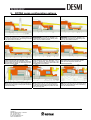
21.1.2 Setting the axial clearance
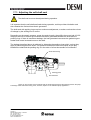
The axial clearance is set by means of:
Types HD, CD, PD: Adjusting screws pos. CT/bearing covers pos. CS/CR
Type GP:
Adjusting screws pos. KX/KY/muff coupling pos. DB
Type ED:
Adjusting screws pos. E/NM/front cover pos. AA
Type CC:
Adjusting screws pos. E/NM/front cover pos. AA or
Adjusting screws pos. E/front cover pos. AA/shim ring(s)
pos. AS
See the position numbers in the section entitled “Spare parts drawings”/“Spare parts list”.
In the case of pumps installed in a pipe system, the axial clearance is set by turning the pump’s
adjusting screws to a given angle.
The angle is defined as follows:
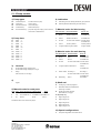
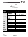
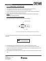
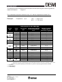
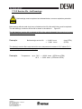
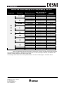
1. The axial clearance can be seen in the table in Figure 33: ___________________
2. Find/measure the size of the adjusting screws for pump type:__________________
3. Based on the size of the adjusting screws, read off the adjusting screws’ pitch –
Figure 35: _______________
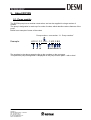
4. Insert the figures obtained in the formula
Figure 35: ___________________
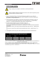
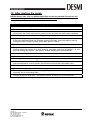
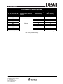
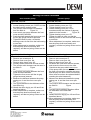
5. Turn the adjusting screws in pairs to the angle obtained, to ensure balanced installation.
See the setting procedure in the table in
Figure 37.
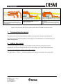
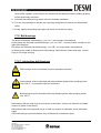
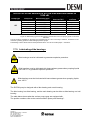
If necessary, see Figure 36, which shows the angle for a single surface on the hexagonal
bolt head.
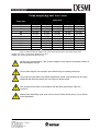
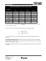
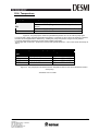
Axial clearance
Pump size
Normal axial
clearance*
Pumps with
spec. tolerances**
26/33
0.10
0.125
0.20
0.25
41
0.10
0.15
0.20
0.30
51/66
0.15
0.20
0.30
0.40
81/101
0.20
0.25
0.40
0.50
126/151
0.30
0.375
0.60
0.75
152
0.35
0.45
0.70
0.90
201
0.40
0.50
0.80
1.0
Figure 32: The axial clearance for the various pump sizes for normal pumps and pumps with special
tolerances respectively. This table applies to pump types HD, CD, PD, GP, CC and ED.
* Pumps made of stainless steel are set with 0.10 mm more play than specified.
DESMI A/S
Tagholm 1
DK-9400 Nørresundby – Denmark
Tel.: +45 96 32 81 11
Fax +45 98 17 54 99
E-mail: [email protected]
Web: www.desmi.com
60