1
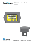
MODEL 205D-L
Flow Computer
USER’S MANUAL
HP-299
November 2002
107 Kitty Hawk Lane, P.O. Box 2145, Elizabeth City, NC 27906-2145
800-628-4584 252-331-1997 FAX 252-331-2886
www.hofferflow.com E-mail: [email protected]
NOTICE
Hoffer Flow Controls, Inc. makes no warranty of any kind with regard
to this material, including, but not limited to, the implied warranties of
merchantability and fitness for a particular purpose.
This manual has been provided as an aid in installing, connecting,
calibrating, operating, and servicing this unit. Every precaution for
accuracy has been taken in the preparation of this manual; however,
Hoffer Flow Controls, Inc. neither assumes responsibility for any
omissions or errors that may appear nor assumes liability for any
damages that result from the use of the products in accordance with
information contained in the manual.
HOFFER FLOW CONTROLS' policy is to provide a user manual for each item
supplied. Therefore, all applicable user manuals should be examined before
attempting to install or otherwise connect a number of related subsystems.
During installation, care must be taken to select the correct interconnecting wiring
drawing. The choice of an incorrect connection drawing may result in damage to
the system and/or one of the components.
Please review the complete model number of each item to be connected and locate
the appropriate manual(s) and/or drawing(s). Identify all model numbers exactly
before making any connections. A number of options and accessories may be
added to the main instrument, which are not shown on the basic user wiring.
Consult the appropriate option or accessory user manual before connecting it to the
system. In many cases, a system wiring drawing is available and may be requested
from Hoffer Flow Controls.
This document contains proprietary information, which is protected by
copyright. All rights are reserved. No part of this document may be
photocopied, reproduced, or translated to another language without the prior
written consent of Hoffer Flow Controls, Inc.
HOFFER FLOW CONTROLS’ policy is to make running changes, not model
changes, whenever an improvement is possible. This affords our customers the
latest in technology and engineering. The information contained in this
document is subject to change without notice.
THIS WARRANTY IS EXPRESSLY IN LIEU OF ALL OTHER
WARRANTIES, EXPRESSED OR IMPLIED, INCLUDING ANY
IMPLIED WARRANTY OF MERCHANTABILITY OR FITNESS FOR
A PARTICULAR PURPOSE. HFC SHALL NOT BE LIABLE FOR ANY LOSS
OR DAMAGE RESULTING, DIRECTLY OR INDIRECTLY, FROM THE USE OR
LOSS OF USE OF THE GOODS. WITHOUT LIMITING THE GENERALITY OF THE
FOREGOING, THIS EXCLUSION FROM LIABILITY EMBRACES THE
PURCHASER'S EXPENSES FOR DOWNTIME OR FOR MAKING UP DOWNTIME,
DAMAGES FOR WHICH THE PURCHASER MAY BE LIABLE TO OTHER
PERSONS, DAMAGES TO PROPERTY, AND INJURY TO OR DEATH OF ANY
PERSONS. HFC NEITHER ASSUMES NOR AUTHORIZES ANY PERSON TO
ASSUME FOR IT ANY OTHER LIABILITY IN CONNECTION WITH THE SALE OR
USE OF HFC'S GOODS, AND THERE ARE NO ORAL AGREEMENTS OR
WARRANTIES COLLATERAL TO OR AFFECTING THE AGREEMENT.
PURCHASER'S SOLE AND EXCLUSIVE REMEDY IS THE REPAIR AND/OR
REPLACEMENT OF NONCONFORMING GOODS AS PROVIDED IN THE PRECEDING
PARAGRAPHS. HFC SHALL NOT BE LIABLE FOR ANY OTHER DAMAGES
WHATSOEVER
INCLUDING
INDIRECT,
INCIDENTAL,
OR
CONSEQUENTIALDAMAGES.
HFC 9907
Limited Warranty POLICY FOR Hoffer Flow Controls
HOFFER FLOW CONTROLS, INC. ("HFC") warrants HFC's Precision Series and API
Series of turbine flowmeters to be free from defects in material and workmanship under
normal use and service, only if such goods have been properly selected for the service
intended, properly installed and properly operated and maintained as described in the
turbine flowmeter manual. Reference "turbine flowmeter manual" for specific details.
This warranty shall extend for a period of five (5) years from the date of shipment to the
original purchaser and covers the Precision Series and API Series of flowmeters All other
HFC products carry a one (1) year warranty. This warranty is extended only to the
original purchaser ("Purchaser"). Purchaser's sole and exclusive remedy is the repair
and/or replacement of nonconforming goods as provided in the following paragraphs.
In the event Purchaser believes the Hoffer product is defective, the product must be
returned to HFC, transportation prepaid by Purchaser, within the appropriate warranty
period relative to the product. If HFC's inspection determines that the workmanship or
materials are defective and the required maintenance has been performed and, has been
properly installed and operated, the product will be either repaired or replaced, at HFC's
sole determination, free of additional charge, and the goods will be returned,
transportation paid by HFC, using a transportation method selected by HFC.
Prior to returning the product to HFC, Purchaser must obtain a Returned Material
Authorization (RMA) Number from HFC's Customer Service Department within 30 days
after discovery of a purported breach of warranty, but not later than the warranty period;
otherwise, such claims shall be deemed waived. See the Return Requests/inquiries
Section of this manual.
If HFC's inspection reveals the Hoffer product to be free of defects in material and
workmanship or such inspection reveals the goods were improperly used, improperly
installed, and/or improperly selected for service intended, HFC will notify the purchaser
in writing and will deliver the goods back to Purchaser upon receipt of Purchaser's
written instructions and agreement to pay the cost of transportation. If Purchaser does not
respond within thirty (30) days after notice from HFC, the goods will be disposed of in
HFC's discretion.
HFC does not warrant the product to meet the requirements of any safety code of any
state, municipality, or other jurisdiction, and Purchaser assumes all risk and liability
whatsoever resulting from the use thereof, whether used singlely or in combination with
other machines or apparatus.
This warranty shall not apply to any HFC product or parts thereof, which have been
repaired outside HFC's factory or altered in any way, or have been subject to misuse,
negligence, or accident, or have not been operated in accordance with HFC's printed
instructions or have been operated under conditions more severe than, or otherwise
exceeding, those set forth in the specifications.
FOR NON-WARRANTY REPAIRS OR CALIBRATIONS, consult
HOFFER FLOW CONTROLS for current repair/calibration charges.
Have the following information available BEFORE contacting HOFFER
FLOW CONTROLS:
1. P.O. number to cover the COST of the repair/calibration,
2. Model and serial number of the product, and
3. Repair instructions and/or specific problems relative to the product.
HFC 9907
CONTENTS
1.
Introduction
1
1.1 Model Number Designation ........................................................ 3
2.
Specification
4
3.
Operation
7
3.1 Front Panel Operation ................................................................. 9
3.2 Single and Quadrature Inputs .................................................... 11
3.3 Calculation of Rate and Total.................................................... 12
3.3.1 Frequency Input ...........................................................12
3.3.2 Analog Input ................................................................13
3.3.3 Filtering........................................................................14
3.4 Total Conversion....................................................................... 16
3.5 Non-Linearity Correction.......................................................... 17
3.6 The Output Pulse and Flow Alarm............................................ 19
4.
Temperature Compensation
21
4.1 Temperature Input (RTD OR 4-20mA)..................................... 22
4.1.1 RTD Input ....................................................................22
4.1.2 4-20mA ........................................................................22
4.2 Volume Correction for General Liquids ................................... 23
4.3 Density Correction for General Liquids.................................... 25
4.3.1 Volumetric Flowmeters................................................25
4.3.2 Differential Pressure Devices.......................................26
4.4 Compensation for Petroleum Liquids........................................ 27
4.5 Compensation for Liquefied Petroleum Gas (LPG) .................. 29
4.6 Density Meter Input .................................................................. 30
5.
Options
31
5.1 The 4-20mA Output Option ...................................................... 31
5.1.1 Load Specification .......................................................32
5.1.2 Calculation ...................................................................32
5.2 The RS232/422/485 Interface Option ....................................... 35
5.2.1 Hardware......................................................................35
5.2.2 Multipoint Communication..........................................36
5.2.3 Communication Protocol .............................................38
5.3 The Relay Output Option .......................................................... 40
Model 205D-L
HP-299
6.
Configuration
41
6.1 Configuring the Setup Parameters............................................. 43
6.2 Configuring the Options............................................................ 49
6.3 Checking the Input Signal ......................................................... 52
7.
Input Circuits
54
7.1 Flow Inputs ............................................................................... 54
7.1.1 Frequency Inputs..........................................................54
7.1.2 Analog Flow Input .......................................................60
7.2 Temperature or Density Input ................................................... 61
8.
Installation
63
8.1 General ...................................................................................... 63
8.2 Terminal Wiring Designations .................................................. 65
9.
Trouble Shooting
66
9.1 Error Codes ............................................................................... 66
Model 205D-L
HP-299
Introduction
1
1. Introduction
The Model 205D-L Flow Computers use temperature correction to
calculate the volumetric flow for liquids at standard reference
conditions.
This manual covers the Model 205D-L series which accepts most
frequency and pulse signals, including mV outputs from turbine
flowmeters and two wire proximity switch outputs. The instrument is
fully configurable, with all calculation constants set via the front panel
switches and stored permanently in a non-volatile memory.
Mass flow can also be calculated from the temperature input and the
volumetric flow input. Therefore, the Model 205D-L series Flow
Computer will enable relatively low cost mass flow measurement using
positive displacement or turbine flowmeters and an RTD.
The Model 205D-L is ideally suited to custody transfer applications
and includes the API/ASTM equations covering general petroleum
products and LPG. Quadrature signal inputs are provided, where it is
required to ensure the integrity of the flow signal, or to measure bidirectional flow.
Two versions of the instrument are available; the Model 205D-LR with
direct RTD input and the Model 205D-LA with a 4-20mA temperature
input.
Both offer the following temperature compensation:
1.
Density Correction
A five point temperature-density curve can be programmed, and
the MASS flow calculated.
2.
Volume Correction for General Liquids
The thermal Coefficient of Expansion of the liquid can be
programmed and a reference temperature defined for volume
correction to that reference.
3.
Petroleums
Volumetric correction to 15°C or 60°F for Crude, Oils, Jet Fuel,
and Gasoline as determined by API/ASTM Table 54A, 54B, and
54D for metric units and Tables 24A, 24B, and 24D for US units.
Model 205D-L
HP-299
2
4.
Introduction
Liquid Petroleum Gas
Volumetric correction to 15°C or 60°C for LPG as determined by
Tables 54 and 34 of the API/ASTM standards.
In addition, the Model 205D-LA accepts a 4-20mA signal from a
Density Meter and uses this input to calculate mass flow.
This instrument conforms to the EMC-Directive of the Council of
European Communities 89/336/EEC and the following standards:
Generic Emission Standard EN 50081-1
Residential, Commercial &
Light Industry Environment.
Generic Emission Standard EN 50081-2
Industrial Environment.
Generic Immunity Standard EN 50082-1
Residential, Commercial &
Light Industry Environment.
Generic Immunity Standard EN 50082-2
Industrial Environment.
In order to comply with these standards, the wiring instructions in
Section 8 must be followed.
Model 205D-L
HP-299
Introduction
3
1.1 Model Number Designation
The Model number of an instrument describes which input and output
options are installed and the AC voltage rating.
MODEL 205D DIGITAL FLOW COMPUTER
(TO BE USED ONLY WHEN APPROVALS ARE REQUIRED)
MODEL 205D-( A )-( B )-( C )-( D )-( E )
INPUTS
ANALOG & COMMUNICATIONS
POWER
MOUNTING (ENCLOSURES)
OPTIONS
INPUTS (SELECT ONLY ONE OPTION)
MODEL 205D-( A )-( )-( )-( )-( )
OPTION ( A )
(1)
BASIC UNIT/SINGLE CHANNEL*
(LA) 4-20 MA TEMPERATURE*
(LR) RTD, 4 WIRE LINEARIZED
(Q)
QUADRATURE BI-DIRECTIONAL FLOW*
(S)
ADD/SUBTRACT, TWO FLOW INPUTS
*SEE NOTE 3
ANALOG & COMMUNICATIONS
MODEL 205D-( )-( B )-( )-( )-( )
OPTION ( B )
(0)
NO OPTIONS OTHER THAN SCALED OPEN COLLECTOR
STANDARD ALL OPTIONS
(1)
4-20 MA ISOLATED
(2)
RS232/422/485
(3)
HIGH/LOW FLOW ALARMS*
(4)
4-20 MA ISOLATED & HIGH/LOW FLOW ALARMS*
(5)
RS232/422/485 & HIGH/LOW FLOW ALARMS*
POWER
MODEL 205D-( )-( )-( C )-( )-( )
OPTION ( C )
(A)
95-135 VAC 50/60 HZ AND 11.5-28.5 VDC SELECT
(C)
190-260 VAC 50/60 HZ
Model 205D-L
HP-299
Introduction
3A
MOUNTING (ENCLOSURES)
MODEL 205D-( )-( )-( )-( D )-( )
OPTION ( D )
(1)
PANEL MOUNT (STD)
(2)
NEMA 4X, WHITE FIBERGLASS
(2B)
NEMA 4X, ALUMINUM WITH HEAVY DUTY EXTERNAL SWITCHES
(CEX) CENELEC FLAME-PROOF, CSA & SAA APPROVED Eexd11BT6
(EX) UL/CSA EXPLOSION-PROOF ENCLOSURE
OPTIONS
MODEL 205D-( )-( )-( )-( )-( E )
OPTION ( E )
(H)
50 W HEATER (SPECIFY 12 VDC, 115 VAC OR 220 VAC)
(B)
BACKLIGHTING DISPLAY
(C)
CONFORMAL COATING
(CE)
INTERFERENCE CE COMPLIANCE
(NTEP) WEIGHTS & MEASURES CUSTODY TRANSFER*
(UL)
ELECTRICAL ETL (US) APPROVED TO UL508 & CSA
(CEN) CENELEC, CSA NRTL/C AND SAA APPROVAL
*SEE NOTE 7.
NOTES:
1.
LCD DISPLAY 6 DIGIT 0.7" (17.8MM) HIGH, NON-VOLATILE TO TEN YEARS.
2.
TRANSDUCER SUPPLY 8-24 VDC @ 50 MA MAX., FIELD ADJUSTABLE.
3.
10 POINT LINEARIZATION WITH INPUT OPTIONS (LA), (LR) AND (Q).
THE (Q)OPTION CAN BE CONFIGURED WITH EITHER THE (LA) OR (LR)
OPTION. SINGLE POINT ‘K’ FACTOR WITH INPUT OPTIONS (1) AND (S).
4.
BOTH MAGNETIC COIL AND HALL EFFECT INPUTS ACCEPTED.
5.
HI/LO ALARMS TWO SPDT, SWITCHING CURRENT MAX 5 AMS @ 250 VAC
OR 30 VDC, MAX. SWITCHING POWER.
6.
(LR)
(LA)
7.
AVAILABLE WITH (LA) AND (LR) OPTIONS ONLY.
TEMPERATURE RANGE
RTD INPUT. . . . . . . . . . . . . . . . . . . . . . . . -148 TO +392 DEG. F.
4-20 MA INPUT:
GENERAL LIQUIDS. . . . . . . . . . -459 TO +392 DEG. F.
PETROLEUMS. . . . . . . . . . . . . . . -148 TO +392 DEG. F.
LPG. . . . . . . . . . . . . . . . . . .. . . . . . . -49 TO +140 DEG. F.
Model 205D-L
HP-299
4
Specification
2. Specification
General
Display:
Display Update Rate:
Transducer Supply:
Power Requirements:
6 digit LCD. 0.7" (17.8mm) high digits
0.25 seconds
8-24VDC field adjustable
50mA maximum
DC: 11.5 to 28.5 volts
60mA typical current (no options)
AC: 95-135 VAC or 190-260 VAC (Set
internally at factory)
Operating Temperature:
Dimensions:
Cutout:
0°C to 55°C standard
5.7" (144mm) wide x 2.8" (72mm) high x
7.0" (178mm) deep
5.5" (139mm) wide x 2.6" (67mm) high
Frequency Input
Frequency Range:
Input Circuits:
Scaling Range:
Non-Linear Correction:
Minimum:
0.25Hz on Rate
0Hz on Total
Maximum: 10KHz (single input)
2.5KHz (quadrature input)
See Section 6.1
0.1000 to 50,000
Up to 10 corrections points
RTD Input (LR Option)
Temperature
Measurement Range:
Measurement
Accuracy:
RTD Type:
Linearity Correction:
Model 205D-L
-100°C (-148°F) to 200°C (392°F)
0.1°C
Platinum PT100
Internally Compensated
HP-299
Specification
5
4-20mA Inputs (LA Option)
Measured:
Input Impedance:
Measurement
Accuracy:
Isolation:
Flow, temperature, or density
250 ohms
0.05%
Inputs are not isolated
Relay Outputs
Maximum Switching Power:
Maximum Switching Voltage:
Maximum Switching Current:
1250VA
250VAC, 30VDC
5 Amps
4-20mA Output
Resolution:
Accuracy:
Maximum Load:
Isolation:
10 bits
Better than 0.05%
500 ohms internally powered,
950 ohms from 24VDC
Output is isolated
Pulse Output
Pulse Width:
Maximum Duty Cycle:
Output:
Scaling:
10msec (negative going pulse)
49 pulses per second
Open collector transistor will sink
100mA.
The pulse output is scaled and
outputs one pulse each time the
accumulated total increments.
Non-linearity Correction
Number of Points:
Correction between points:
Model 205D-L
10 maximum
Linear interpolation
HP-299
6
Specification
Temperature Correction
Density Correction for
General Liquids:
A five point temperature-density table
can be programmed.
LPG:
Temperature Range: -273°C (-459°F) to
200°C (392°F).
To API/ASTM Tables 34 and 54
Petroleums:
Accuracy: 0.04% for metric.
0.12% for US.
Temperature Range: -45°C (-49°F) to
60°C (140°F)
Correction to API/ASTM Tables:
Crude:
Tables 24A and 54A.
Gas, Jet, Oils: Tables 24B and 54B.
Lube Oil:
Tables 24D and 54D.
Volume Correction for
General Liquids:
Accuracy:
0.075%
Temperature Range: -100°C (-148°F) to
200°C (392°F)
Correction to any base temperature using
a constant thermal coefficient of
expansion.
Accuracy:
0.05%
Temperature Range: -273°C (-459°F) to
200°C (392°F).
Density Meter Input (LA Option only)
A density meter with 4-20mA output can
be connected, in place of a temperature
sensor, to provide a mass flow reading.
Model 205D-L
HP-299
6A
Specification
This page intentionally left blank.
Model 205D-L
HP-299
Operation
7
3. Operation
The Model 205D-L uses a low power CMOS microprocessor to
perform all control functions and calculations.
The instrument is fully configurable with all operating parameters and
calculation constants user settable.
(See Section 5 entitled
"Configuration" for information on configuring.) All parameters and
constants are stored in a non-volatile memory which retains data
without battery backup for a minimum of 10 years.
A block diagram of the two input options of the instrument is shown
below.
LR Option
•
Temperature Input directly from a PT100 RTD.
•
Frequency Input from a single flowmeter with a single or dual
frequency output.
The dual frequency unit (termed "Quadrature") is often required in
custody transfer applications to ensure the integrity of the flow
signal and to measure bi-directional flow.
Model 205D-L
HP-299
8
Operation
LA Option
•
Temperature Input from a temperature transmitter (4-20mA).
•
Either a Frequency Input (Single or Quadrature) or Analog
(4-20mA) from a single flowmeter.
With both options, the -LR and -LA, a DIL switch on the rear panel
enables the frequency input circuit to be set to interface with a wide
range of flowmeters.
Model 205D-L
HP-299
Operation
9
3.1 Front Panel Operation
The display will normally show the Rate or Net Total, as selected by
the RATE or TOTAL keys on the front facia. An LED in the key panel
will light to indicate which function is currently displayed.
The DISPLAY key can be used to display the following additional
information:
Accumulated Total
On the first press of the DISPLAY key, the display shows Acctot
for one second followed by the actual total.
Temperature
If temperature compensation is selected, the second press of the
DISPLAY key will show the product temperature as:
xxx.x F or xxx.x C
If a Density Meter input is selected rather than temperature, the
density (and not temperature) will be displayed. The displays will
read "DENS" for one second followed by the actual density value.
Gross Total
If temperature compensation is selected, the third press of the
DISPLAY key will show GROSS for one second followed by the
actual gross total.
If the DISPLAY key is again pressed, the display will revert to the
Rate or Total display. In any display function, if the DISPLAY key
has not been pressed for 5 seconds, the display will automatically
go back to the Rate or Total display.
Model 205D-L
HP-299
10
Operation
The display functions are defined as follows:
RATE
Rate of flow in engineering units, with
temperature correction (if selected).
TOTAL
The Net resettable total. The Net Total is
temperature corrected (if selected).
ACCUMULATED
The Accumulated Total is a Net Total (i.e.,
temperature compensated) but it is not
resettable via the front RESET key.
GROSS TOTAL
The Gross Total is the total without
temperature correction. The Gross Total will
be reset each time the RESET key is pressed.
TEMPERATURE
The instantaneous temperature of the fluid
being measured, in °C or °F depending on
which units are selected when the instrument
was configured.
All values of rate and total will also be compensated for flowmeter
non-linearity, if this function is selected.
On reaching the maximum displayed total, all totals will roll over to
zero and continue totalizing. If, at any time, power is lost or the
instrument is switched off, the totals will be stored in the non-volatile
memory. When power is switched back on to the instrument, the stored
totals will be recalled from memory and the totals will be incremented
from the last values.
Model 205D-L
HP-299
Operation
11
3.2 Single and Quadrature Inputs
In most industrial flowmetering applications, a frequency producing
flowmeter has only a single output.
However, in many custody transfer applications, it is a requirement that
the flowmeter has two outputs so that the integrity of the signal can be
assured. This usually requires a turbine meter to have two coils, or a
positive displacement meter to have two pulse units.
The Model 205D-L models can interface to flowmeters fitted with two
sensors and connections to the flowmeters are outlined in Section 7.1.1.
The quadrature input has two functions.
1.
To detect a difference in the number of pulses from each
input during delivery.
The instrument will alarm if the pulse difference (since
reset) exceeds 1 in 1000 pulses. When an alarm condition
exists the totals will cease counting and will freeze at the
last total prior to the alarm.
On detection of the alarm condition, the alarm output on
terminal 7 will go low (energise) and the display will cease
counting. The output can be used to shutoff the flow or to
warn the operator. The display will also periodically flash
the error message, ERR 13.
The alarm condition is reset by pressing the DISPLAY key.
2.
Bi-directional Flow.
The 205D-L models have the ability to detect forward and
reverse flow. The inputs must be connected with channel 1
being the 90° flow signal and channel 2 being the 0° signal.
For forward/reverse detection to function correctly, there
must be clear definition of the input signals.
Model 205D-L
HP-299
12
Operation
3.3 Calculation of Rate and Total
3.3.1
Frequency Input
The flowrate, R, is calculated as follows:
R=
where
f
H
S
f ×H
S
is the input frequency in Hz.
is the timebase of rate and is 1 for seconds, 60 for
minutes,3600 for hours, and 86,400 for days.
is the Scaling Factor.
The Scaling Factor S, is equal to the K-factor of the flowmeter
expressed in pulses per unit volume.
The flowrate, R, as expressed in the above equation, is the volumetric
flowrate at flow conditions. With temperature compensation, the above
flowrate, R, is corrected to give the flowrate at a base temperature or
the mass flow. Temperature Correction is covered in detail in Section
4.
The user sets the Scaling Factor and selects the timebase during the
configuration process as detailed in Section 5 of this manual.
When non-linearity correction is configured, up to 10 scaling factors
are entered to cover different frequency ranges. The instrument will
then automatically select the correct scaling factor to be applied at the
measured frequency.
Model 205D-L
HP-299
Operation
3.3.2
13
Analog Input
With –LA option, where the analog input is selected rather than
frequency, the flowrate at flow conditions, R, is calculated as follows:
R = An × S
Where
A
S
n
represents the input signal; 0 at 4mA and 1 at
20mA.
is the Span and is the flowrate at 20mA.
is 1 for a linear input or ½ for inputs from
differential pressure devices.
The user sets S and n, during the configuration procedure, as detailed in
Section 6 of this manual.
Note that the Model 205D-LA will only handle flow signals from
differential pressure type flow devices (i.e., when n = ½), for:
1.
2.
3.
No temperature compensation.
Density Correction for general liquids
A density meter input.
A cutoff can also be set for analog inputs which prevents the display of
flowrate and integration of the input signal at low flowrates. The cutoff
is set as a percentage of the Span, S.
Note that when the input signal drops below 3.5mA a signal error will
occur. The instrument will beep and the display will alternate between
the current total and the word "SIGNAL".
Model 205D-L
HP-299
14
Operation
3.3.3
Filtering
Frequency fluctuations caused by pulsating flow through a flowmeter,
often makes the Rate impossible to read with any precision.
The Flow Computer has a digital filter which will average out these
fluctuations and enable the Rate to be read to four digit accuracy. The
degree of filtering is fully configurable which means that highly
accurate and stable readings can be obtained without excessive lag.
When the Rate is retransmitted via the 4-20mA output, the filtering will
also average out any fluctuations on the output.
The diagram below shows a pulsating signal input together with the
effect of filtering.
As a guideline to the degree of filtering to be used, the following table
shows the response to a step change in input. The value, A, is the filter
constant which is set during the configuration process. The times for
the display value to reach 90% and 99% of full swing are given in
seconds for different values of A.
Model 205D-L
HP-299
Operation
A
90%
99%
1
0
0
2
1
2
4
2
4
6
3
6
10
5
11
15
8
17
20
11
22
25
14
28
35
20
40
45
25
51
60
34
69
75
43
86
90
52
103
99
57
113
15
Table 1 – Response to a step Input (in seconds).
Note: If A is set to 1, there is NO filtering of the input signal.
Model 205D-L
HP-299
16
Operation
3.4 Total Conversion
The Total Conversion feature enables the rate to be displayed in one
engineering unit (e.g., gallons/minute) and the totals to be displayed in
another engineering unit (e.g., barrels).
The Scaling Factor is always set in the unit relating to Rate and the
Total Conversion constant is a division factor which can be used to
convert the totals to the different unit. The Total Conversion factor
affects the net, accumulated, and gross totals and is limited between
0.01 and 2000.
For Example
If the Rate is required in gallons per minute:
1. The Scaling Factor would be set to pulses per gallon
2. The timebase would be set to minutes
If the Totals are required in barrels:
3. The Total Conversion factor is set to 42 (there are 42 gallons in
a barrel). All totals, including the Batch Quantity and Batch
Total, will now be in barrels.
Some common units are given below together with the Total
Conversion constant (TOTCON) which should be set.
Rate∗
Gallons (US)/
Liters/
ml/
Mgallons/
∗
Totals
Barrels (oil)
Kiloliters
Liters
Acre-feet
TOTCON
42.00
1000
1000
0.32587
Units per second, minute, hour, or day. The timebase is set separately
during configuration.
Model 205D-L
HP-299
Operation
17
3.5 Non-Linearity Correction
Non-linearity correction enables the instrument to correct for known
non-linearities in the flowmeter. This feature is not selectable for
analog flow inputs.
Up to 10 frequencies and scaling factors can be programmed. Data on
the flowmeter non-linearity can usually be supplied by the flowmeter
manufacturer in the form of a Calibration Certificate, and is the result
of individual tests on a flowmeter over a range of flowrates. The
Certificate will list a number of flowrates or frequencies with the
measured K-factor (e.g., pulses per gallon or litre) at each flowrate.
The following diagram graphs the change in scaling factor with
frequency for a hypothetical flowmeter. The heavy black line
represents the actual scaling factor of the flowmeter, while the light
black line is the approximation used in the instrument.
Linear Interpolation is used between points on the curve, except for
Factor 1 which maintains a constant value between Frequency 1 and the
maximum input frequency.
During Calibration, the program requires the user to input a frequency
and the Scaling Factor (K-factor of the flowmeter) at up to 10 points on
the curve. Generally these points will correspond to those shown on
the Certificate.
Model 205D-L
HP-299
18
Operation
If any frequency is set to 0Hz (Frequency 6 in the preceding example),
then the program will require no further correction points to be
programmed. Hence, the user can program any number of correction
points up to a maximum of 10. Note that if all 10 correction points are
required, then Frequency 10 will automatically be assigned the value of
0Hz.
Model 205D-L
HP-299
Operation
19
3.6 The Output Pulse and Flow Alarm
An OUTPUT PULSE is available on terminal 10 for driving remote
counters and produces a pulse each time the Accumulated Total
increments by one digit. For example, if the Accumulated Total has a
resolution of 0.01 gallons, a pulse is produced each 0.01 gallons.
The pulse is a current sinking pulse of approximately 10msec produced
by an open collector transistor and can sink up to 100mA. The
maximum pulse rate is limited to 49 pulses per second and the
resolution on the Accumulated Total must be set so that the
Accumulated Total increments at less than 49 counts per second.
Note that due to the uneven pulse output spacing on this output, the
pulse output cannot be used to drive rate indicators.
The FLOW ALARM uses an identical circuit to the Output Pulse, and
is on terminal 7.
The Flow Alarm is used by the Quadrature Input, if selected, and will
output an error signal if there is a difference between the input pulses as
described in Section 3.2. If an analog flow input signal is selected, the
Flow Alarm output will activate if the flow signal falls below 3.5mA.
The Flow Alarm output will switch "on" (i.e., the signal goes low)
whenever an alarm condition exists. The Alarm will switch "off" (i.e.,
the signal goes high) when the alarm is reset by pressing the DISPLAY
key.
Model 205D-L
HP-299
20
Operation
Connection of the Output Pulse is as follows:
Driving an External Relay or Impulse Counter
Driving a Logic Input such as a PLC or Electronic Counter
Model 205D-L
HP-299
Temperature Compensation
21
4. Temperature Compensation
Temperature compensation gives the instrument the capability to
correct for changes in volume of the measured liquid with temperature.
There are four methods of compensation which can be selected.
1.
2.
3.
4.
Density correction for general liquids with known
temperature density characteristics.
A five point
temperature-density curve can be programmed and the
MASS flow calculated.
Volume correction for general liquids using a thermal
coefficient of expansion. This method is useful for
correction to a base volume over relatively small changes in
temperature.
Correction for Petroleum Liquids to US and International
standards for a wide range of petroleums, to a base
temperature of 60°F/15°C.
Correction for LPG to US and International standards, to a
base temperature of 60°F/15°C.
In addition, the Model 205D-LA will also accept a 4-20mA signal from
a Density Meter (in place of a temperature input) and use this input to
calculate MASS flow.
Model 205D-L
HP-299
22
Temperature Compensation
4.1 Temperature Input (RTD OR 4-20mA)
The Model 205D is available with either a PT100 Platinum RTD input
(-LR) or with a 4-20mA input (-LA). The input option must be
specified when ordering.
The temperature inputs are continually checked to ensure that they are
within the specified limits and an Input Error will be displayed as "Err
12" if the 4-20mA input drops below 3.5mA or if the RTD resistance is
outside the valid resistance ranges.
4.1.1
RTD Input
Instruments with RTD inputs are identified by the Model number
205D-LR. A four wire temperature measurement is used to give
high accuracy and, internally, the software will compensate for the
non-linearity of the RTD. Details of the installation are given in
Section 7.2.
During calibration, a "temperature adjust facility" enables the
temperature reading to be adjusted. This allows for manufacturing
tolerances on the RTD to be corrected.
4.1.2
4-20mA
A two wire 4-20mA input from a temperature transmitter or
density meter can be input to instruments with the Model number
designation 205D-LA.
With a 4-20mA input, a linear relationship is assumed over the
span of the transmitter. The temperatures or densities at 4mA and
20mA are both programmable during the Calibration routine.
Model 205D-L
HP-299
Temperature Compensation
23
4.2 Volume Correction for General Liquids
For general liquids, a linear correction factor can be applied, to give
volumetric flow at base conditions. The flow equation is:
Volume Corrected Flowrate =
where
Volumetric Flowrate
1 + (T f − Tb )× a
Tf is flow temperature (°C or °F).
Tb is base temperature (°C or °F).
a is Thermal Coefficient of Expansion per °C or °F.
The Volumetric Flowrate is the flowrate defined in sections 3.3.1 and
3.3.2
The Thermal Coefficient of Expansion, "a", for a liquid can be
determined empirically or can be found in chemical engineering texts.
A list of coefficients is given on the following page for a number of
common petroleum products at 15°C.
Model 205D-L
HP-299
24
Temperature Compensation
Thermal Coefficients of Expansion at 15°C (60°F)
PRODUCT
DENSITY AT 15°C
(kg/litre)
COEFFICIENT OF
EXPANSION/°C
LPG - Propane
- Butane
Aviation Gasoline
Petrol
Aviation Jet A-1
Lighting Kerosene
Power Kerosene
Heating Oil
Automotive Distillate
Industrial Diesel Fuel
Fuel Oil: High Sulphur
Low Sulphur
Bitumen
Crude Oil (Bass Strait)
Benzene
Toluene
Xylene
White Spirit
Mineral Turpentine
Lube Oils:
SAE 10
SAE 20
SAE 30
SAE 40
SAE 50
Water
0.510
0.580
0.695
0.740
0.795
0.790
0.810
0.820
0.840
0.855
0.980
0.900
1.020
0.796
0.880
0.870
0.860
0.780
0.820
0.00290
0.00200
0.00120
0.00110
0.00094
0.00094
0.00087
0.00087
0.00084
0.00082
0.00070
0.00075
0.00063
0.00087
0.00120
0.00110
0.00100
0.00095
0.00087
0.880
0.890
0.890
0.900
0.900
1.000
0.00077
0.00076
0.00076
0.00074
0.00074
0.00031
Model 205D-L
HP-299
Temperature Compensation
25
4.3 Density Correction for General Liquids
If density correction for general liquids is selected, a five point
temperature-density table can be programmed. The instrument uses
this table to determine the density of the product after measuring the
temperature of the fluid.
For known fluids, the temperature-density characteristics are well
documented in standard chemical reference books. One to five
correction points can be programmed and the user inputs the number of
points during programming.
The instrument will also allow a constant density value to be
programmed by selecting only one correction point. In this case, the
temperature input is ignored. This feature is useful if the temperature
sensor is removed for maintenance.
4.3.1
Volumetric Flowmeters
The flow equation for volumetric flowmeters is:
Mass Flow = R x Density
where
R
is the flowrate defined in sections
3.3.1 and 3.3.2.
Density is the density determined from the
temperature-density table.
When programming the temperature-density table, the density can
be programmed in any units, but the units must be consistent with
the flowrate R, and the required units for MASS flow. For
example, if R is in litres and the mass is required in kilograms, then
the density must obviously be programmed as kg/litre.
Model 205D-L
HP-299
26
Temperature Compensation
The above figure shows the temperature-density points for a 4
point table. Above tp4, the curve has the same gradient as between
tp3 and tp4 and below tp1, the curve has the same gradient as
between tp1 and tp2.
4.3.2
Differential Pressure Devices
For differential pressure devices the Mass flowrate is defined as:
Mass Flow = S × A1 / 2 × Density1 / 2
where S =
Mass Flowrate at 20mA
(Density at reference conditions )1 / 2
The Mass flowrate at 20mA and the corresponding reference density
are provided by the flowmeter supplier and S is then calculated from
the above equation and programmed during Calibration.
For differential pressure devices, the Gross Total is calculated as:
Volume Flow = S × A1/ 2 ×
Model 205D-L
1
Density1/ 2
HP-299
Temperature Compensation
27
4.4 Compensation for Petroleum Liquids
The petroleum correction program uses the American Petroleum
Institute equations described in API Standard 2540. For US units, the
equations leading to Table 24A, 24B, and 24D are used and, for metric
units, Table 54A, 54B, and 54D equations are used. These Tables are
entitled:
Table 24A
Correction of Volume for Generalized Crude
Oils to 60°F against Relative Density 60/60°F.
Table 24B
Correction of Volume for Generalized Products
to 60°F Against Relative Density 60/60°F
Table 24D
Correction of Volume for Generalized
Lubricating Oils to 60°F against Relative
Density 60/60°F.
Table 54A
Correction of Volume for Generalized Crude
Oils to 15°C against Density at 15°C.
Table 54B
Correction of Volume for Generalized Products
to 15°C Against Density at 15°C.
Table 54D
Correction of Volume for Generalized
Lubricating Oils to 15°C against Density at
15°C.
Based on the programmed density and the measured temperature, the
software derives a volume correction factor (VCF). The gross
(uncompensated) rate is multiplied by the VCF to give the net
compensated total.
For US units, the density is programmed as the Relative Density (SG)
and the volume is referenced to 60°F. For Metric units, the density is
programmed as the Density in kg/m3 and the volume is referenced to
15°C.
Five product groups are defined by the equations and, during the
Calibration routine, the relevant product group must be selected. The
product groups and the relevant densities which can be programmed are
as follows:
Model 205D-L
HP-299
28
Temperature Compensation
Relative Density
Density (kg/m3)
Crude Oil
0.751 - 1.000
750 - 1000
Jet Fuels, Kerosene +
Solvent
0.751 - 0.850
750 - 850
Gasoline
0.641 - 0.800
640 - 800
Lube Oil
0.851 - 0.960
850 - 960
Diesel, Heating + Fuel Oils
0.801 - 1.100
800 - 1100
Product Group
When programming the density, the values must be entered within
these specified limits otherwise an error message will be displayed,
prompting the operator to check the parameters.
Model 205D-L
HP-299
Temperature Compensation
29
4.5 Compensation for Liquefied Petroleum
Gas (LPG)
The LPG correction program uses the American Petroleum Institute
tables to volume correct the LPG to a reference temperature of 60°F for
US units and 15°C for Metric units. The program uses an internally
stored table to correct to the following standards:
US units
API Table 34 for correction of volume to 60°F
against relative density 60/60°F for liquefied
petroleum gases.
Metric units
API Table 54 for Reduction of Volume to 15°C
against density at 15°C for liquefied petroleum
gases.
For US units the density is programmed as the Relative Density (SG)
and the volume is referenced to 60°F. For Metric units the density is
entered as kg/litre and the volume is referenced to 15°C.
When programming the density, the values must be within the
following limits, otherwise an error message will be displayed.
US units
Metric units
0.501 to 0.600
0.500 to 0.600 kg/litre
The temperature compensation is performed over a temperature range
of -45°C to 60°C (-49°F to 140°F).
Model 205D-L
HP-299
30
Temperature Compensation
4.6 Density Meter Input
Density correction is available on the Model 205D-LA where a density
meter is connected across the temperature inputs (Terminal 5) in place
of a temperature transmitter. The densitometer must have a 4-20mA
output.
During Calibration, the density at 4mA and 20mA can be programmed
and the mass flow for volumetric flowmeters is:
Mass Flow = R x Density
where
R
is the flowrate defined in sections
3.3.1 and 3.3.2.
Density is the density input.
If the input falls below 3.5mA, an error status, "Err 12" is displayed.
Differential Pressure Devices
For differential pressure devices the Mass flowrate is defined as:
Mass Flow = S × A1 / 2 × Density1 / 2
where S =
Mass Flowrate at 20mA
(Density at reference conditions )1 / 2
The Mass flowrate at 20mA and the corresponding reference density
are provided by the flowmeter supplier and S is then calculated from
the above equation and programmed during Calibration.
For differential pressure devices, the Gross Total is calculated as:
Volume Flow = S × A1/ 2 ×
Model 205D-L
1
Density1/ 2
HP-299
Options 31
5. Options
5.1 The 4-20mA Output Option
The 4-20mA output option provides an analog output of RATE as
either a 4-20mA current or a 0-10 Volt level. All output signals are
electrically isolated from the instrument power supply and signal inputs
to ensure minimum interference. The 4-20mA is directly proportional
to the displayed rate.
Either 2 wire current transmission is available with the loop powered
internally or 3 wire transmission from an external loop supply.
A block diagram of the output is shown below and various methods of
interconnection are outlined on the following pages.
Model 205D-L
HP-299
32
Options
5.1.1
Load Specification
Maximum load which the output can drive:
Internally powered loop:
500 ohms
Externally powered:
R = (V-5)/0.02
Where
V
is the external loop voltage
R
is the maximum load in ohms.
Output impedance of 0-10 Volt source:
5.1.2
100 ohms
Calculation
Parameters relating to this option are configured when calibrating the
instrument (see Section 5) and provide for:
♦
♦
♦
Defining the rate which is equivalent to 4mA or 0 volts.
Defining the rate which is equivalent to 20mA or 10 volts.
Selecting the output range as 4-20mA (which also gives 2-10
volts on the voltage output circuit) or as 0-10 volts (which
gives 0-20mA on the current output circuit).
By being independently able to set the output range, the instrument can
effectively be programmed to amplify the input signal. In driving chart
recorders, for example, this enables the output to zoom in on a
particular operating area, instead of having to display the full operating
range of the transducer.
For example, 4mA may be set as 0 gallons/min and 20mA as 100
gallon/min. However, the user could set 4mA as representing 100
gallons/min and 20mA as representing 120 gallons/min.
For rates or displayed values above and below the maximum and
minimum values the output will remain at its 20mA or 4mA level
respectively.
It should be noted that the output will be updated every 0.25 seconds in
unison with the display and, between updates, the output value is
constant .
Model 205D-L
HP-299
Options 33
Voltage Output Configurations
Two Wire Transmission (Internal Supply)
Model 205D-L
HP-299
34
Options
Three Wire Transmission (External Supply)
Model 205D-L
HP-299
Options 35
5.2 The RS232/422/485 Interface Option
With this option installed, the circuits for both the RS232 and
RS422/485 interfaces are provided as standard. They can be used to
interface to both printers and computers. A number of standard printer
protocols are built into the instrument.
5.2.1
Hardware
The following diagram provides an overview of the
RS232/RS422/RS485 communications hardware. All three interfaces
are available on the rear terminal strips and the user can select either
one by making the appropriate connections.
The RS232 interface is primarily used with printers or for simple
communication with a computer over a short distance. The RS422 and
RS485 interfaces are used for communication over a long distance or in
applications requiring multipoint communication.
Model 205D-L
HP-299
36
Options
5.2.2
Multipoint Communication
Multipoint Communication is a system whereby a number of
instruments can be addressed over a dual twisted pair interface. Up to
32 instruments can be connected to a common bus using the RS422 and
RS485 interfaces as shown below.
To convert the RS422 interface to an RS485 interface, the RS422 (-)
Data In Terminal must be connected to the RS422 (-) Data Out
Terminal and the RS422 (+) Data In Terminal must be connected to the
RS422 (+) Data Out Terminal. These connections will convert the
RS422 4 wire interface to the RS485 2 wire interface, as shown in
Figure 2.
Each instrument can be configured with a unique address which is used
by the Master Controller (e.g., an IBM/PC) to identify each instrument.
The Controller will send the address down the line and will alert the
relevant instrument. Subsequent software protocol will control the
flow of data between the Controller and the Instrument.
Figure 1 RS422 Interface
Model 205D-L
HP-299
Options 37
Figure 2 RS485 Interface
Model 205D-L
HP-299
38
Options
5.2.3
Communication Protocol
The RS232/422/485 option has a real time clock and enables the time
and date to be set and printed on tickets. The date format can be
European (day/month/year) or USA (month/day/year) while the time is
on a 24 hour clock.
Note that the clock will only retain its time for 3 days (minimum) if
there is no power connected to the instrument. After this period, the
clock may need to be reset.
The baud rate, parity, and word length can be selected during
configuration and the user must ensure that these correspond to the
setting on the printer or computer with which the instrument is
communicating.
The software protocols can be selected during configuration to provide
standard interfaces to a number of printers and computers. Since other
interfaces will continue to be added, the user should consult the factory
for the latest protocols and/or printer drivers.
Printer
A ticket is printed each time the RESET key is pressed. The instrument
prints the ticket before resetting the resettable total. Protocols are
provided to drive the following printers:
1
2
3
4
5
6
Standard Computer Printer (Note that the printer must have an
RS232 Serial Interface)
EPSON CTM290 Slip Printer
Contrec Model 624
EPSON TM290-2 Slip Printer
Contrec Model 632-2
Syntest SP-210
Consult with the factory if any other printer is to be interfaced with the
instrument.
The tickets can also be printed with a number of different units of
measure including liters and gallons. The units of measure are
selectable from a pre-programmed list.
A CTS input is provided and prevents the instrument from transmitting
any further characters to a printer if the printer buffer is full. The CTS
input is usually connected to the "Data Buffer Full" output from the
printer.
Model 205D-L
HP-299
Options 39
If the printer buffer is large enough to handle the message output from
the instrument, then this input need not be used and should be left
unconnected.
Computer
The instrument receives and transmits messages in ASCII with all
command strings to the instrument terminated by a carriage return.
While replies from the instrument are terminated with a carriage return
and a line feed.
Xon/Xoff protocol is also supported and the instrument will
automatically determine if the message sent by the host computer is
preceded by an Xoff character. If it does recognize an Xoff as the first
character of a command string, the instrument will automatically switch
to the Xoff/Xon protocol beginning and ending all messages with Xoff
and Xon characters respectively. Xoff/Xon protocol is only available
when the RS232 interface is selected.
During configuration, the instrument can be configured to operate in a
full duplex or half duplex transmission mode. In full duplex mode, all
commands sent to the instrument are echoed back to the host computer.
In half duplex, the commands are not echoed.
Model 205D-L
HP-299
40
Options
5.3 The Relay Output Option
The Relay output option consists of two Form C relays which can be
preset during configuration to energize when the rate or displayed value
exceeds or drops below the preset values.
The "low" relay is energized whenever the rate is below the preset
value, and the "high" relay is energized whenever the rate exceeds the
preset value. The preset values are programmed during configuration
as described in section 5.
Model 205D-L
HP-299
Configuration
41
6. Configuration
The Configuration process enables the Setup Parameters to be
configured, as well as enabling the input signals to be checked.
The configuration process can be entered in one of two ways:
1.
2.
By connecting a wire link (or switch) to the rear terminal strip
across terminals 1 and 2
By pressing the TOTAL key and while holding, pressing the
RESET key. Both keys must then be held for approximately 6
seconds. This second method of access can be disabled during
the configuration so that it is only possible to enter the
configuration process via the link across terminals 1 and 2.
The key switch actions are during Configuration are as follows:
RATE
changes a flashing digit to the next digit.
TOTAL
increments a flashing digit or changes a
parameter selection.
RESET
resets a flashing digit to zero.
DISPLAY
steps through the configuration sequences.
Note that the arrows in the RATE and TOTAL key switches indicate
that these switches can be used to change and increment digits
respectively.
In stepping through the configuration sequence, the Parameter
Description is always displayed first followed by the actual value or
parameter. When a value or parameter can be changed, it is always
shown as flashing and the LEDs in the switch panels are lit if that key
switch can be used to change a value.
On first entering the Configuration routine, the display will show:
CAL
Option
Test
Model 205D-L
Setup Program parameters
Options (if installed)
Check Input Signals
HP-299
42
Configuration
End
Exit to Normal Operation
The user can toggle between these modes using the TOTAL key and by
using the DISPLAY key select the appropriate mode.
To exit Configuration, step through the Setup program or Test program
until the end and press the DISPLAY key when End is displayed
(ensure the configuration link is removed).
Model 205D-L
HP-299
Configuration
43
6.1 Configuring the Setup Parameters
Step
Display
1
CAL
OPTION
TEST
END
Description
Text
Ref
Setup Program Parameters
Options (if installed)
Check Input Signals
Exit to normal operation
6.2
6.3
The following steps are displayed when CAL is selected.
2
RESTOT Reset all totals to zero.
xxxxxx
To clear all totals (net, gross, and
accumulated) press the RESET key once.
3
FL INP Select either a single frequency input or a
quadrature input (i.e., two pulses from a single
flowmeter). The analog input on the -LA
option can also be selected.
single
quad
analog
4
Single Input
Quadrature Input
Analog Input (only with –LA option)
CORRCT Select either a linear input or non-linear
correction for the flowmeter input. If an
analog input is selected the input relationship
is either linear or square root.
Linear
Nonlin
Sq rt
Model 205D-L
3.2
3.2.1
Linear Correction
Non-Linear Correction (only on freq input) 3.5
Square Root Input (only if analog input)
3.3.2
HP-299
44
Configuration
Step
5
Display
Description
Text
Ref
SCALE Scaling Factor.
If linear correction is selected, the scaling factor is programmed as
follows.
3.3
Fact
Enter the Scaling factor (K-factor) of the
flowmeter.
If non-linearity correction is to be programmed, up to 10
frequencies and scaling factors can be entered.
Freq 1 Freq1 is programmed to the first frequency 3.5
point in the range of 0 to 9999Hz.
Fact 1 This is the K-factor of the flowmeter (i.e.,
pulses per gal, etc.) at Freq1. The digits before
the decimal point (whole numbers) are
programmed first, followed by the decimals.
The scaling factor can be programmed in the
range of 0.1000 to 50,000.
Freq2 Freq2 is programmed to the second frequency
point. If any Freq is set to 0, no further
correction points can be programmed and the
non-linearity correction is limited to that
number of points.
Fact 2 Scaling Factor 2.
to
Fact 10 Scaling Factor 10. Note that Freq10 is not
displayed since it must always be zero.
If an Analog input is programmed, the value, S, is entered.
Fact
6
7
This is the value, S, which must be entered.
CUTOFF Displayed only if an analog input is selected.
x.xx
The Cutoff prevents display and integration
of the flowrate below x.xx% of the span.
F dPt
Model 205D-L
Number of decimal points which the Rate is to
be displayed between 0 to 0.00000.
HP-299
Configuration
Step
Display
8
t.base
60secs
hours
days
secs
9
Text
Ref
The Timebase which the Rate is calculated
must be entered as:
3.3
units/min
units/hour
units/day
units/second
FILTER The filter constant for filtering the Rate
display.
1
to
99
10
Description
3.3.3
No filtering.
Very heavy filtering.
TOTCON A division factor to convert the totals to
different units from those used for rate (e.g.,
gallons/min and barrels).
1
x.xxxx
3.4
Rate and Totals have the same engineering
units.
Other factors can be programmed between
0.01 and 2000.
11
t.dPt
Number of decimal points which the Net
resettable Total is displayed between 0 to
0.000.
12
A.dPt
Number of decimal points which the
Accumulated (non resettable) total is displayed
between 0 to 0.000.
8
t.c.
The type of Temperature Compensation can be
selected as follows:
none
genliq
gendns
petrol
LPG
dens
No temperature compensation
Volume Correction for General liquids
Density Correction for general liquids
Compensation for Petroleum products
Compensation for Liquid Petroleum Gas
Density Meter Input (-LA Option only)
Model 205D-L
45
4
4.2
4.3
4.4
4.5
4.6
HP-299
46
Step
Configuration
Display
Description
Text
Ref
If "none" (no temperature compensation) is selected the program will go to
Step 20 (ACCESS).
If a Density Meter Input is selected the following steps are
displayed:
14
15
d4
The density at 4mA input is entered.
4.6
The density at 20mA input is entered.
d20
The program will now go to Step 21.
All other selections result in the following steps being displayed:
14
t.
Select either US units or metric units as the
basis of the temperature compensation
4
US units
°F
Metric units
°C
If the instrument has a direct RTD input (-LR option) the
temperature can be adjusted (offset) to correct for the RTD
tolerance.
15
ADJ t
xx.xx
Adjust the temperature displayed during test
Input the offset. (The first digit is 0 for
positive or - for negative.)
If the instrument has a 4-20mA temperature input (-LA option),
then the 4mA and 20mA points are entered.
15
IP4
Enter the temperature that corresponds to 4mA
in either °F or °C depending on the units
selected in Step 14.
16
IP20
Enter the temperature that corresponds to
20mA
Model 205D-L
4.1
HP-299
Configuration
Step
Display
Description
47
Text
Ref
Program steps 17 to 19 depend on which option for temperature
compensation was selected in Step 13 and are individually described.
Volume Correction for General Liquids
17
4.2
REF °F The base temperature for the compensation.
Enter the temperature in °F or °C depending on
(°C)
the units selected in Step 14.
18
COEF A Enter the thermal coefficient of change "a" as
a%. Hence if the coefficient of expansion is
0.0029/°C enter the % change as 0.29000.
The program will now go to Step 20.
Density Correction for General Liquids
17
NotP x
18
tp1
19
Number of temperature-density correction
points up to five. If x is set to 1, a fixed
density can be programmed (i.e., the density is
not dependent on the temperature).
4.3
Temperature point 1.
dens1 Density 1.
Up to 5 correction points can be entered.
Petroleums
17
Select the petroleum type.
4.4
CRUDE Crude oils as per tables 24A & 54A.
LUBE Lube oils as per tables 24D & 54D.
OILS
Fuel oils & heating oils, and diesel (tables 24B
& 54B).
JET
Jet fuels, kerosenes and solvents (tables 24B &
54B).
GAS
Gasolines and naphthenes (tables 24B & 54B).
Model 205D-L
HP-299
48
Step
18
Configuration
Display
Description
Text
Ref
dn 60°F US units : use Relative Density (SG).
or
4.4
Metric units : use the Density at 15°C in
kg/m3.
dn 15°C
The program will now go to Step 20.
Liquid Petroleum Gas
17
dn 60°F US units : use the Relative Density (SG)
4.5
Metric units : use the Density in kg/litre
The program will now go to Step 20.
20
ACCESS Enable access to configuration routine via the
front keyboard only.
Front
No Acc
Model 205D-L
Enable access via front keyboard.
Disable access via front keyboard.
HP-299
Configuration
49
6.2 Configuring Options
Step
Display
1
OPTION
TEST
END
CAL
Description
Text
Ref
Options (if installed)
Check Input Signals
Exit to normal operation
Setup Program Parameters
6.2
6.1
If the 4-20mA option is installed, the following will be displayed:
2
OUTPUT Select output option.
4-20
4-20mA (also 2-10 volts).
0-10
0-10 volt (also 0-20mA).
3
OP 4
xxxx
Flowrate at 4mA or 0 volt
4
OP20
xxxx
Flowrate at 20mA or 10 volt
5.1
If the RS232/422/485 option is installed, the following will be displayed:
5
DF
Eur
USA
Date Format.
European (i.e., days/months/years).
USA (i.e., months/days/years).
6
Enter date as:
Date
xx:xx:xx
Years:Months:Days.
7
HOUR
xx:xx
Enter time as a 24 hour clock.
BAUD
xxxx
Baudrate
DATA
7
8
Word length.
8
9
Model 205D-L
5.2
Hours:Minutes.
5.2
300, 600, 1200, 2400, 4800, or 9600
7 bits
8 bits
HP-299
50
Step
Configuration
Display
Description
10
PARITY Parity.
NP
No Parity
OP
Odd Parity
EP
Even Parity.
11
SIGNAL Signal Type.
rs232
RS232
rs422
RS422/RS485
12
13
ID NO
0
1 - 99
Text
Ref
Unit Identification Number.
None
Id Number.
PTYPE xx Printer/Computer Type.
00
01
02
03
04
05
Standard Computer Printer
EPSON CTM 290 Slip Printer
Contrec Model 624 Printer
EPSON TM290-2 Slip Printer
Contrec Model 632-2 Printer
Syntest SP-210 Printer
20
Computer
If a Printer Protocol is selected, the following message is displayed:
14
UNIT xx Units of measurement printed.
00
01
02
03
04
05
06
07
Model 205D-L
None
Liters (Ltrs).
Gallons (Gals)
Barrels (bbls)
Pounds (lbs)
Grams (gms)
Kilograms (kgs)
Tons (tons)
HP-299
Configuration
Step
Display
Description
51
Text
Ref
If a Computer Protocol is selected, the following message is displayed:
14
ECHO
On
Off
ECHO Commands.
Echo (Full Duplex)
No Echo (Half Duplex)
If the relay option is installed, the following is displayed:
15
16
AL: Hi
xxxxxx
High Alarm switch point.
AL: Lo
xxxxxx
Low Alarm switch point.
Model 205D-L
5.3
The high relay energizes when the flowrate
exceeds this value.
5.3
The low relay energizes when the flowrate
fall below this value.
HP-299
52
Configuration
6.3 Checking the Input Signal
Step
Display
1
TEST
END
CAL
OPTION
Description
Text
Ref
Check Input Signals
Exit to normal operation
Setup Program Parameters
Options (if installed)
6.1
6.2
The following steps are displayed when TEST is selected.
2
Sr x.xx
Software revision number.
If the instrument has the -LA option is installed and temperature or density
correction selected, the display will show:
3
T4-20
Displayed for 1 second to indicate input from
the 4-20mA temperature input.
Or
D4-20
xx.xx
Input current displayed.
If the instrument has the -LR option is installed and temperature correction
selected, the display will show:
3
RTD
xxx.xx
Displayed for 1 second to indicate the RTD.
Measured temperature displayed.
Use the DISPLAY switch to step to the Flow Input
If the Flow Input is a Single frequency input, the display will show:
4
Freq
xxxx. x
Model 205D-L
Displayed for 1 second followed by the actual
frequency.
Frequency in Hz.
HP-299
Configuration
Step
Display
Description
53
Text
Ref
If the Flow Input is a Quadrature frequency input, the display will show:
4
Freq
xxxx. x
Displayed for 1 second followed by the actual
frequency.
Frequency in Hz. If the flow is reversing a
negative sign will appear.
If the Flow Input is an analog signal, the display will show:
4
F4-20
xx.xx
Displayed for 1 second followed by the actual
current.
Current in mA
If the RS232/422/485 option is installed, the display will then show:
5
CLOC Clock.
xx:xx:xx
Time in Hours:Mins:Sec.
Model 205D-L
HP-299
Input Circuits
53A
This page intentionally left blank.
Model 205D-L
HP-299
54
Input Circuits
7. Input Circuits
7.1 Flow Inputs
7.1.1
Frequency Inputs
The 205D-L unit has two pulse input circuits:
•
Channel 1 is used with both single and quadrature input. The
input will interface directly to:
_
_
_
_
•
Turbine Flowmeters
Logic Signals
Open Collector Outputs
Reed Switches
Channel 2 is used only when a quadrature input is selected and
becomes the 0° input while Channel 1 becomes the 90° input.
The channel can interface directly to:
_
_
_
Open Collector Outputs
Logic Signals
Reed Switches
The frequency input circuits can be configured by the user to interface
with most flowmeters. A small 8 position DIP switch on the rear of the
instrument is used to configure the input for different signal types.
Model 205D-L
HP-299
Input Circuits
55
Switch Settings
The following switch settings are recommended for different input
signal types.
Note: Input types d and e are only available on Channel 1. Channel 2
is limited to signal types a to c.
Input Signal Type
Input Terminals
CH1
Switch Settings
CH2
(+) (-) (+) (-)
1
2
3
4
5
6
7
8
a. Logic Signal,
CMOS, Pulse
9
8
3
8 off off off off on off off off
b. Open Collector or
Reed switch
9
8
3
8 off off off off on off on off
c. Namur Proximity
(set DC out to 8
volts)
11 9 11 3
on off on on on on off off
Channel 1 Only
d. Switch or Reed
Switch with
debounce circuit
(200Hz max)
9
8
off off off off on off on
on
e. Coil (20mV P-P
minimum)
9
8
off on off off off off off off
General Specification
Switching Threshold:
2.5 Volts (except for input type c and e)
Maximum Input Voltage:
50V peak
Input Impedance:
Input type a:
Input types b & d:
Input type c:
Input type e:
Model 205D-L
100K on Channel 1
10K on Channel 2
10K
1K
100K
HP-299
56
Input Circuits
Powering of Sensors
The 205D Series has a regulated power supply output which can be
used to power sensors. A trimpot on the rear of the instrument allows
the voltage to be adjusted in the range of 8-24 volts and the output can
supply a maximum of 50mA.
Model 205D-L
HP-299
Input Circuits
57
The Frequency Input Circuit
Model 205D-L
HP-299
58
Input Circuits
1.MAG Coil
2.Redi-Pulse, CMOS or Pulse
3.Redi-Pulse, Open Collector
Model 205D-L
HP-299
Input Circuits
59
4.Squarewave, CMOS or Pulse
5.Open-Collector
6.Reed Switch
Model 205D-L
HP-299
60
Input Circuits
7.1.2
Analog Flow Input
On instruments with the –LA option, there is provision to accept an
analog (4-20mA) input from a flowmeter. When the analog input is
selected, the pulse inputs cannot be used.
The flowmeter and temperature (or density) sensor are connected as
follows:
Shielding:
When shielding the input signals, the shield should be
connected to the case earth and not connected at the transmitter end
(i.e., ground at the instrument end only).
Model 205D-L
HP-299
Input Circuits
61
7.2 Temperature or Density Input
The Model 205D Flow Computer can be supplied with the following
optional temperature (density) inputs:
-LR option
Direct 4-wire Platinum RTD (PT100)
-LA option
4-20mA input which can be used for temperature
or density
RTD
Four wire RTD measurement is the most accurate form of measurement
and can be used for measurements with the RTD up to 300 feet from
the instrument. It is recommended to use shielded cable when
interfacing to the RTD.
A two or three wire RTD can be used in place of the 4-wire RTD, but 4
wires must be taken to the RTD and the signal and current wires joined
as close to the RTD as possible.
With direct RTD measurement, the program automatically corrects for
the non-linearity in the RTD.
Model 205D-L
HP-299
62
Input Circuits
When wiring the RTD, care must be taken to ensure the (+) of the
current on terminal 4 is connected to the same side of the RTD as the
(+) of the signal on terminal 5. The RTD has no polarity and can be
connected in either direction.
4-20mA
This input can function as either a temperature or density input. The
instrument enables the 4mA and the 20mA points to be programmed.
Unlike the direct RTD measurement, no correction is made for the nonlinearity of the temperature or density sensor.
Model 205D-L
HP-299
Input Circuits
62A
This page intentionally left blank.
Model 205D-L
HP-299
Installation
63
8. Installation
8.1 General
Terminal designations for the Model 205D-L Flow Computer are given
on the following pages. The cutout hole in the panel should be 5.5"
(139mm) wide x 2.6" (67mm) high. Two side clips are supplied to
secure the instrument into the panel.
A case grounding point is provided via a ground lug on the side of the
case. Note that this grounding point is for the case only and there is
complete electrical isolation between this point and all electronic
circuits. For EMC purposes or when the instrument is connected to AC
power source, this point must be connected to a good earth ground
using a multi-stranded, braided wire or strap. All relay options are
totally isolated from the case and from the internal circuitry.
A Supply Output Voltage is provided to power sensors. This output
will provide a regulated voltage of 8 to 24 volts and the voltage is
adjustable by means of the potentiometer on the rear panel. Maximum
current is 50mA and the instrument comes with the voltage factory set
at 24 Volts, unless specified otherwise. When the instrument is
powered from a DC power source, the maximum output voltage on the
Supply Output is the DC Input Voltage less 3.5 volts.
The instrument will operate from either 12-28 volts DC or from the AC
line. The AC voltage is factory set to either 95 - 135 VAC (110 VAC
nominal) or 190 - 260 VAC (220 VAC nominal). An internal AC
transformer provides full isolation between the AC line and the
electronic circuits.
The DC Ground terminal 12 provides a common ground for the 12-28
Volt power input, the 8 - 24 Volt output, and the pulse output.
It is good practice to use shielded cables for all signal connections to
the instrument. Care must be taken to separate signal cables from
power cables so as to minimize interference. Overall shields should be
connected to the case earth at the instrument end only. This connection
should be as short as possible and connected to the grounding lug on
the side of the case.
Model 205D-L
HP-299
64
Installation
In order to comply with the requirements for Electromagnetic
Compatibility as per EMC-Directive 89/336/EEC of the Council of
European Community, this wiring practice is mandatory.
Although it is also possible to connect shields to the signal ground
(terminal 2) this practice is not in accordance with EMC directives.
RC Networks for Interference Suppression
When driving highly inductive loads with the control relays, it is
recommended that RC suppression networks (often called "Snubbers")
are used for two reasons:
§
To limit the amount of electrical noise caused by arcing across
the relay contacts which may, in extreme cases, cause the
microprocessor to act erratically.
§
To protect the relay contacts against premature wear through
pitting.
RC suppression networks consist of a capacitor and series resistor and
are commonly available in the electrical industry. The values of R and
C are dependant entirely on the load. However, if the user is unsure of
the type of snubber to use, values of 0.25µF and 100 ohms will usually
suffice. Note that only AC voltage approved RC suppression networks
should be used.
The basic principle of operation is that the capacitor prevents a series of
sparks from arcing across the contact as the contact breaks. The series
resistor limits the current through the contact when the contact first
makes
Model 205D-L
HP-299
Installation
65
8.2 Terminal Wiring Designations
Terminal
Model 205D-LR
Configuration Link
Signal Ground
Flow Pulse Input (Channel 2)
PT100 I (+)
PT100 Signal (+)
PT100 Signal (-)
Flow Alarm
Flow Common (-)
Flow Pulse Input (Channel 1)
Pulse Out
DC Power Out (8-24 Vdc)
DC Ground (-)
DC Power Input (+)
PT100 I (-)
Model 205D-LA
Configuration Link
Signal Ground
Flow Pulse Input (Channel 2)
Not Used
Temperature Input (4-20mA)
Not Used
Flow Alarm
Flow Common (-)
Flow Pulse Input (Channel 1)
Pulse Out
DC Power Out (8-24 Vdc)
DC Ground (-)
DC Power Input (+)
Flow Input (4-20mA)
20
21
22
23
24
25
26
27
Analog Output Option
Not Used
0 Volts
0-10 Volts
-12 Volts
I (-)
I (+)
+15 Volts
Not Used
RS232/422/485 Option
RS232 Signal Ground
RS232 Data in
RS232 Data Out
RS422/485 (-) Data Out
RS422/485 (+) Data Out
RS422/485 (-) Data In
RS422/485 (+) Data In
RS232 CTS
Terminal
31
32
33
34
35
36
Relay Option
Relay 2 - Normally Open
Relay 2 - Normally Closed
Relay 2 - Common
Relay 1 - Normally Open
Relay 1 - Normally Closed
Relay 1 - Common
1
2
3
4
5
6
7
8
9
10
11
12
13
14
Terminal
Model 205D-L
HP-299
Installation
65A
This page intentionally left blank.
Model 205D-L
HP-299
66
Trouble Shooting
9. Trouble Shooting
9.1 Error Codes
The instrument has extensive self test facilities and will display an error
code if it detects an invalid condition. If the instrument displays an
error code other than those listed below, please contact the factory.
Error codes are displayed as "Err ##" and a list of the commonly
encountered codes are given below:
Input Errors
11
12
13
14
SIGNAL
Invalid input configuration programmed.
The Temperature or Density input is out of range.
Quadrature error detected (i.e., unequal pulse count on
the inputs).
Communications Input error (RS232/422/485
interface).
Analog Flow input below 3.5mA (-LA option only).
Output Errors
21
22
23
Invalid output configuration.
Communications error - Baud rate not set.
Communications error - Printer fault.
Configuration Errors
30
31
32
33
33
Model 205D-L
Zero Value not allowed.
Outside allowable Temperature range.
Outside allowable Density range.
Invalid Printer Type.
Invalid Volume Units selected.
HP-299